EP4119474A1 - Centering mechanism and paper-sheet handling device - Google Patents
Centering mechanism and paper-sheet handling device Download PDFInfo
- Publication number
- EP4119474A1 EP4119474A1 EP20923817.9A EP20923817A EP4119474A1 EP 4119474 A1 EP4119474 A1 EP 4119474A1 EP 20923817 A EP20923817 A EP 20923817A EP 4119474 A1 EP4119474 A1 EP 4119474A1
- Authority
- EP
- European Patent Office
- Prior art keywords
- unit
- centering
- paper sheet
- conveyance
- bank bill
- Prior art date
- Legal status (The legal status is an assumption and is not a legal conclusion. Google has not performed a legal analysis and makes no representation as to the accuracy of the status listed.)
- Granted
Links
Images




Classifications
-
- B—PERFORMING OPERATIONS; TRANSPORTING
- B65—CONVEYING; PACKING; STORING; HANDLING THIN OR FILAMENTARY MATERIAL
- B65H—HANDLING THIN OR FILAMENTARY MATERIAL, e.g. SHEETS, WEBS, CABLES
- B65H9/00—Registering, e.g. orientating, articles; Devices therefor
- B65H9/16—Inclined tape, roller, or like article-forwarding side registers
- B65H9/166—Roller
-
- B—PERFORMING OPERATIONS; TRANSPORTING
- B65—CONVEYING; PACKING; STORING; HANDLING THIN OR FILAMENTARY MATERIAL
- B65H—HANDLING THIN OR FILAMENTARY MATERIAL, e.g. SHEETS, WEBS, CABLES
- B65H9/00—Registering, e.g. orientating, articles; Devices therefor
- B65H9/002—Registering, e.g. orientating, articles; Devices therefor changing orientation of sheet by only controlling movement of the forwarding means, i.e. without the use of stop or register wall
-
- G—PHYSICS
- G07—CHECKING-DEVICES
- G07D—HANDLING OF COINS OR VALUABLE PAPERS, e.g. TESTING, SORTING BY DENOMINATIONS, COUNTING, DISPENSING, CHANGING OR DEPOSITING
- G07D11/00—Devices accepting coins; Devices accepting, dispensing, sorting or counting valuable papers
- G07D11/10—Mechanical details
- G07D11/16—Handling of valuable papers
- G07D11/17—Aligning
-
- B—PERFORMING OPERATIONS; TRANSPORTING
- B65—CONVEYING; PACKING; STORING; HANDLING THIN OR FILAMENTARY MATERIAL
- B65H—HANDLING THIN OR FILAMENTARY MATERIAL, e.g. SHEETS, WEBS, CABLES
- B65H2403/00—Power transmission; Driving means
- B65H2403/40—Toothed gearings
-
- B—PERFORMING OPERATIONS; TRANSPORTING
- B65—CONVEYING; PACKING; STORING; HANDLING THIN OR FILAMENTARY MATERIAL
- B65H—HANDLING THIN OR FILAMENTARY MATERIAL, e.g. SHEETS, WEBS, CABLES
- B65H2404/00—Parts for transporting or guiding the handled material
- B65H2404/10—Rollers
- B65H2404/14—Roller pairs
- B65H2404/142—Roller pairs arranged on movable frame
- B65H2404/1421—Roller pairs arranged on movable frame rotating, pivoting or oscillating around an axis, e.g. parallel to the roller axis
- B65H2404/14212—Roller pairs arranged on movable frame rotating, pivoting or oscillating around an axis, e.g. parallel to the roller axis rotating, pivoting or oscillating around an axis perpendicular to the roller axis
-
- B—PERFORMING OPERATIONS; TRANSPORTING
- B65—CONVEYING; PACKING; STORING; HANDLING THIN OR FILAMENTARY MATERIAL
- B65H—HANDLING THIN OR FILAMENTARY MATERIAL, e.g. SHEETS, WEBS, CABLES
- B65H2404/00—Parts for transporting or guiding the handled material
- B65H2404/10—Rollers
- B65H2404/15—Roller assembly, particular roller arrangement
- B65H2404/152—Arrangement of roller on a movable frame
- B65H2404/1521—Arrangement of roller on a movable frame rotating, pivoting or oscillating around an axis, e.g. parallel to the roller axis
- B65H2404/15212—Arrangement of roller on a movable frame rotating, pivoting or oscillating around an axis, e.g. parallel to the roller axis rotating, pivoting or oscillating around an axis perpendicular to the roller axis
-
- B—PERFORMING OPERATIONS; TRANSPORTING
- B65—CONVEYING; PACKING; STORING; HANDLING THIN OR FILAMENTARY MATERIAL
- B65H—HANDLING THIN OR FILAMENTARY MATERIAL, e.g. SHEETS, WEBS, CABLES
- B65H2701/00—Handled material; Storage means
- B65H2701/10—Handled articles or webs
- B65H2701/19—Specific article or web
- B65H2701/1912—Banknotes, bills and cheques or the like
-
- G—PHYSICS
- G07—CHECKING-DEVICES
- G07D—HANDLING OF COINS OR VALUABLE PAPERS, e.g. TESTING, SORTING BY DENOMINATIONS, COUNTING, DISPENSING, CHANGING OR DEPOSITING
- G07D2211/00—Paper-money handling devices
Definitions
- the present invention relates to a centering mechanism and a paper sheet handling apparatus.
- ATM Automated Teller Machine
- a conceivable method checks whether a bank bill is positioned closer to one side in the width direction, using a sensor, and if the bank bill is positioned closer to one side in the width direction, the method improves the slanted state by linearly moving a conveyance roller for conveying bank bills, in the width direction. The method will be described with reference to Figs. 8A and 8B .
- Figs. 8A and 8B are explanatory diagrams for describing centering of a bank bill B in a reference art.
- a pair of conveyance belts 201 and 201 for conveying the bank bill B in a conveyance direction D are arrayed at an interval in a width direction W orthogonal to the conveyance direction D.
- a pair of conveyance rollers 202 and 202 for conveying the bank bill B are arranged between the pair of conveyance belts 201 and 201 in the width direction W. Note that the pair of conveyance belts 201 and 201 are arranged over a region including an upstream side and a downstream side in the conveyance direction D of the pair of conveyance rollers 202 and 202.
- the slanted state is detected by a sensor (not illustrated) arranged on the upstream side in the conveyance direction D of the pair of conveyance belts 201 and 201. Based on the slanted state being a detection result of the sensor, as illustrated in Fig. 8B , the pair of conveyance rollers 202 and 202 linearly move in the width direction W (toward a left direction in Fig. 8B ) while conveying the bank bill B. The center of the bank bill B in the width direction W thereby gets closer to the center C.
- the pair of conveyance belts 201 and 201 and conveyance members such as conveyance rollers that face these conveyance belts 201 and 201 convey the bank bill B while pinching the bank bill B at sufficiently-low pinch pressure (conveyance force) in such a manner as not to disturb centering of the bank bill B that is performed by linearly moving the pair of conveyance rollers 202 and 202 in the width direction W.
- the object of the present invention is to provide a centering mechanism and a paper sheet handling apparatus that can perform centering of paper sheets while surely conveying paper sheets.
- a centering mechanism of the present disclosure includes a centering unit configured to convey a paper sheet in a pinched state, and center a position of the paper sheet in a width direction orthogonal to a conveyance direction of the paper sheet by inclining with respect to the conveyance direction, an upstream side conveyance unit that is arranged on an upstream side of the centering unit in the conveyance direction set when the centering unit centers a position of the paper sheet in the width direction, and is configured to convey the paper sheet, and a downstream side conveyance unit that is arranged on a downstream side of the centering unit in the conveyance direction set when the centering unit centers a position of the paper sheet in the width direction, and is configured to convey the paper sheet in a pinched state, in which the paper sheet is delivered to the downstream side conveyance unit from the centering unit in a state in which the centering unit pinches the paper sheet, and the downstream side conveyance unit conveys the paper sheet while pinching the paper sheet at pinch pressure stronger than pinch pressure at which the centering unit pinches the paper
- a paper sheet handling apparatus of the present disclosure includes a centering unit configured to convey a paper sheet in a pinched state, and center a position of the paper sheet in a width direction orthogonal to a conveyance direction of the paper sheet by inclining with respect to the conveyance direction, an upstream side conveyance unit that is arranged on an upstream side of the centering unit in the conveyance direction set when the centering unit centers a position of the paper sheet in the width direction, and is configured to convey the paper sheet, and a downstream side conveyance unit that is arranged on a downstream side of the centering unit in the conveyance direction set when the centering unit centers a position of the paper sheet in the width direction, and is configured to convey the paper sheet in a pinched state, in which the paper sheet is delivered to the downstream side conveyance unit from the centering unit in a state in which the centering unit pinches the paper sheet, and the downstream side conveyance unit conveys the paper sheet while pinching the paper sheet at pinch pressure stronger than pinch pressure at which the centering unit pinch
- centering of paper sheets can be performed while surely conveying paper sheets.
- Fig. 1 is a left side view illustrating an internal configuration of the automatic dealing apparatus 100.
- up-down, front-back, and left-right directions illustrated in Fig. 1 and Figs. 2A to 7C to be described later merely indicate an example in a case where a client side of the automatic dealing apparatus 100 is regarded as a front direction.
- the up-down direction corresponds to a vertical direction
- the front-back and left-right directions correspond to a horizontal direction.
- the automatic dealing apparatus 100 illustrated in Fig. 1 is, for example, an ATM, a Bill Recycle Unit (BRU), a Cash Dispenser (CD), a Teller Cash Recycler (TCR), or the like, and includes a main body unit 110, an intermediate conveyance unit 120, and a storage unit 130.
- the main body unit 110 and the storage unit 130 are arranged in different spaces via a partition (not illustrated), and the intermediate conveyance unit 120 conveys a bank bill B (refer to Fig. 2A ) in such a manner as to penetrate through the above-described partition.
- the bank bill B is an example of a paper sheet.
- the main body unit 110 includes the centering mechanism 1, conveyance units 111 and 113, a determination unit 112, a temporary retention unit 114, a reject unit 115, and a bank bill deposit/withdrawal unit 116. Note that only the main body unit 110 can be regarded as a paper sheet handling apparatus.
- the centering mechanism 1 is arranged between the determination unit 112 and the conveyance unit 113.
- the conveyance unit 111 conveys the bank bill B from the bank bill deposit/withdrawal unit 116 to the determination unit 112, and also conveys the bank bill B between the determination unit 112 and the intermediate conveyance unit 120.
- the determination unit 112 determines true-false, dirt, corner bending, or the like of the bank bill B.
- the determination unit 112 also functions as an example of a slant detection sensor for detecting that the center of the bank bill B is slanted toward either side in a width direction over the center in the width direction of a conveyance path.
- the conveyance unit 113 conveys the bank bill B between the centering mechanism 1 and the temporary retention unit 114, and also conveys the bank bill B from the centering mechanism 1 to the bank bill deposit/withdrawal unit 116.
- the temporary retention unit 114 temporarily stores the bank bill B that has been input to the bank bill deposit/withdrawal unit 116, and determined to be normal by the determination unit 112.
- the reject unit 115 stores the bank bill B not to be returned, among the bank bills B determined to be abnormal by the determination unit 112.
- the bank bill deposit/withdrawal unit 116 includes a front panel 116a, an inlet/outlet port 116b, and a shutter 116c.
- the front panel 116a is arranged on an upper front surface of the automatic dealing apparatus 100 at a slant in the vertical direction and the horizontal direction in such a manner as to be positioned rearward as getting upward.
- the inlet/outlet port 116b is provided on the front panel 1116a.
- the bank bill B input from the inlet/outlet port 116b is conveyed to the conveyance unit 111 by the bank bill deposit/withdrawal unit 116.
- the bank bill B conveyed from the conveyance unit 113 to the bank bill deposit/withdrawal unit 116 is conveyed by the bank bill deposit/withdrawal unit 116 up to a position at which the bank bill B is taken out from the inlet/outlet port 116b.
- the shutter 116c openably blocks the inlet/outlet port 116b. Note that, in Fig. 1 , the shutter 116c in an opened state is indicated by a solid line, and the shutter 116c in a closed state is indicated by a dotted line.
- the intermediate conveyance unit 120 conveys the bank bill B between the main body unit 110 and the storage unit 130.
- the storage unit 130 is arranged below the main body unit 110, and includes a plurality of bank bill storage cassettes 131, 132, 133, 134, and 135, and a storage conveyance unit 136.
- the plurality of bank bill storage cassettes 131 to 135 store the bank bills B of mutually-different money types, for example.
- the bank bill storage cassettes 131 to 135 can discharge the stored bank bills B.
- the bank bills B stored in the bank bill storage cassettes 131 to 135 are used for withdrawal.
- the storage conveyance unit 136 conveys the bank bill B between the intermediate conveyance unit 120 and each of the bank bill storage cassettes 131 to 135.
- Figs. 2A to 2C are explanatory diagrams for describing conveyance paths R1 to R4 of the bank bill B of the automatic dealing apparatus 100.
- the bank bill B input to the bank bill deposit/withdrawal unit 116 is conveyed to the determination unit 112 by the bank bill deposit/withdrawal unit 116 and the conveyance unit 111.
- the bank bill B determined to be normal by the determination unit 112 is conveyed to the temporary retention unit 114 by the centering mechanism 1 and the conveyance unit 113.
- the bank bill B (bogus bill, etc.) determined to be abnormal by the determination unit 112 is returned to the bank bill deposit/withdrawal unit 116 by the conveyance unit 113.
- the bank bills B temporarily stored in the temporary retention unit 114 are conveyed to the bank bill storage cassettes 131 to 135 by the conveyance unit 113, the centering mechanism 1, the determination unit 112, the conveyance unit 111, the intermediate conveyance unit 120, and the storage conveyance unit 136.
- the bank bills B stored in the bank bill storage cassettes 131 to 135 are discharged to the bank bill deposit/withdrawal unit 116 at the time of withdrawal by the storage conveyance unit 136, the intermediate conveyance unit 120, the conveyance unit 111, the determination unit 112, the centering mechanism 1, and the conveyance unit 113.
- Fig. 3 is a front view illustrating the centering mechanism 1.
- Fig. 4 is a front side perspective view illustrating the centering mechanism 1.
- Fig. 5 is a rear side perspective view illustrating the centering mechanism 1.
- Fig. 6 is a cross-sectional view taken along a line VI-VI in Fig. 3 .
- the centering mechanism 1 conveys the bank bills B in both directions from the determination unit 112 to the conveyance unit 113 (refer to Figs. 2A and 2C ), and from the conveyance unit 113 to the determination unit 112 (refer to Fig. 2B ).
- Figs. 3 to 6 and Figs. 7A to 7C to be described later illustrate a conveyance direction D set when a centering unit 10 centers the position of the bank bill B in a width direction W orthogonal to the conveyance direction D, and a conveyance unit on an upstream side in the conveyance direction D is an upstream side conveyance unit 20 and a conveyance unit on a downstream side is a downstream side conveyance unit 30.
- the upstream side conveyance unit 20 functions not only as an upstream side conveyance unit but also as a downstream side conveyance unit
- the downstream side conveyance unit 30 functions not only as a downstream side conveyance unit and but also as an upstream side conveyance unit.
- the centering mechanism 1 includes two centering units 10 and 10, the upstream side conveyance unit 20, the downstream side conveyance unit 30, an arm 40 (an example of a first power transmission unit), a drive unit 50, a crown gear 61 (an example of a fourth gear), two power transmission belts 62 and 62 (an example of second power transmission units), and an entry detection sensor 70.
- the two centering units 10 and 10 are arrayed at an interval in the width direction W (left-right direction).
- the number of the centering units 10 may be one or plural number, but is desirably set to two.
- Each of the two centering units 10 and 10 conveys the bank bill B in a pinched state.
- the two centering units 10 and 10 center the position of the bank bill B in the width direction W by inclining with respect to the conveyance direction D (up-down direction) of the bank bill B, which will be described in detail later.
- Each of the two centering units 10 and 10 includes a conveyance roller 11, a ball roller 12, a rotational shaft 13, a spur gear 14 (an example of a first gear), a crown gear 15 (an example of a second gear), and a support portion 16.
- the conveyance roller 11 and the ball roller 12 face each other in the front-back direction, and convey the bank bill B while pinching the bank bill B at pinch pressure P1 (refer to Fig. 6 ).
- the pinch pressure can be adjusted based on urging force (pressing force) of an elastic member pressing at least one of mutually-facing two conveyance members (rollers or belts) against the bank bill B.
- the pinch pressure can also be adjusted based on an inter-axial distance of mutually-facing two conveyance members, or tensile force of a belt (conveyance member).
- the rotational shaft 13 rotates integrally with the conveyance roller 11. Note that the rotation means being rotatable in both forward and backward directions.
- the spur gear 14 is provided on the rotational shaft 13.
- the crown gear 15 includes teeth provided on the front side, and engages with the spur gear 14. Being driven by the drive unit 50 to be described later, the crown gear 15 rotates around a swing center (front-back direction) around which the centering unit 10 swings.
- the crown gear 15 rotating based on power transmitted from the upstream side conveyance unit 20
- the spur gear 14 engaging with the crown gear 15, and the rotational shaft 13 and the conveyance roller 11 that rotate together with the spur gear 14 rotate, which will be described in detail later.
- the conveyance roller 11 rotates based on power transmitted from the upstream side conveyance unit 20.
- the support portion 16 has a U-shape opened toward the front side, and rotatably supports both ends of the rotational shaft 13.
- the support portion 16 includes an extension portion 16a protruding downward, and an elongated hole 16b provided in the extension portion 16a.
- the elongated hole 16b is elongated in the conveyance direction D than in the width direction W, and provided in such a manner as to penetrate through the extension portion 16a in the front-back direction.
- a pin 42 of the arm 40 to be described later is inserted into the elongated hole 16b.
- the upstream side conveyance unit 20 includes two conveyance belts 21 and 21, four conveyance rollers 22, two rotational shafts 23, four pulleys 24, and a spur gear 25 (an example of a third gear).
- the two conveyance belts 21 and 21 are arrayed at an interval in the width direction W.
- the number of the conveyance belts 21 can be set to an arbitrary number equal to or larger than 1.
- Each of the two conveyance belts 21 and 21 is stretched around the two pulleys 24 and 24 to be described later.
- the four conveyance rollers 22 are arranged in such a manner as to face the respective pulleys 24.
- the two conveyance belts 21 and the four conveyance rollers 22 face each other in the front-back direction, and convey the bank bill B while pinching the bank bill B at pinch pressure P2 (refer to Fig. 6 ).
- the pinch pressure P2 is weaker than the pinch pressure P1 generated by the conveyance roller 11 and the ball roller 12 (P2 ⁇ P1).
- the upstream side conveyance unit 20 delivers the bank bill B to the centering unit 10 in a state in which the centering unit 10 pinches the bank bill B.
- the upstream side conveyance unit 20 is arranged in such a manner as to neighbor the centering unit 10 at an interval shorter than the length of the bank bill B in the conveyance direction D.
- the two rotational shafts 23 extend in the width direction W, and are arrayed at an interval in the conveyance direction D.
- the two of the four pulleys 24 are provided on each of the rotational shafts 23, and the pulleys 24 rotate integrally with the rotational shafts 23.
- the spur gear 25 is provided on a rotational shaft 23 on the centering unit 10 side (lower side), and rotates integrally with the rotational shaft 23.
- the spur gear 25 may be provided on a rotational shaft 33 of the downstream side conveyance unit 30.
- the crown gear 61 and the two power transmission belts 62 and 62 which will be described later, are arranged not on the upstream side conveyance unit 20 side but on the downstream side conveyance unit 30 side.
- the downstream side conveyance unit 30 includes two conveyance belts 31 and 31, four conveyance rollers 32, two rotational shafts 33, and four pulleys 34.
- the two conveyance belts 31 and 31 are arrayed at an interval in the width direction W.
- the number of the conveyance belts 31 can be set to an arbitrary number equal to or larger than 1.
- Each of the two conveyance belts 31 and 31 is stretched around the two pulleys 34 and 34 to be described later.
- the four conveyance rollers 32 are arranged in such a manner as to face the respective pulleys 34.
- the two conveyance belts 31 and the four conveyance rollers 32 face each other in the front-back direction, and convey the bank bill B while pinching the bank bill B at pinch pressure P3 (refer to Fig. 6 ).
- the pinch pressure P3 is stronger than the pinch pressure P1 generated by the conveyance roller 11 and the ball roller 12 (P3 > P1).
- P3 > P1 the pinch pressures P1 to P3 satisfy relationship of P3 > P1 > P2.
- the bank bill B is delivered to the downstream side conveyance unit 30 from the centering unit 10 in a state in which the centering unit 10 pinches the bank bill B.
- the downstream side conveyance unit 30 is arranged in such a manner as to neighbor the centering unit 10 at an interval shorter than the length of the bank bill B in the conveyance direction D.
- the two rotational shafts 33 extend in the width direction W, and are arrayed at an interval in the conveyance direction D.
- the two of the four pulleys 34 are provided on each of the rotational shafts 33, and the pulleys 34 rotate integrally with the rotational shafts 33.
- the arm 40 extends in the width direction W. Teeth 41 engaging with a spur gear 51 provided on an output shaft of the drive unit 50 to be described later are provided on the front surface of a right end (an example of one end) of the arm 40.
- two pins 42 and 42 to be inserted into elongated holes 16b and 16b of two support portions 16 and 16 described above are provided on the arm 40 integrally, for example, in such a manner as to protrude forward.
- the drive unit 50 is a motor, for example, that rotates the spur gear 51 provided on the output shaft extending in the conveyance direction D. By rotating the spur gear 51, the drive unit 50 moves, in the width direction W, the arm 40 including the teeth 41 engaging with the spur gear 51.
- the support portion 16 (the centering unit 10) including the elongated hole 16b into which the pin 42 of the arm 40 is to be inserted thereby swings in such a manner as to incline with respect to the conveyance direction D around a swing center corresponding to the front-back direction.
- the crown gear 61 includes teeth provided on the front side, engages with the spur gear 25 of the upstream side conveyance unit 20, and rotates around a rotational center (front-back direction) parallel to the swing center of the centering unit 10.
- the two power transmission belts 62 connect the crown gear 61 and the two crown gears 15 by being stretched around a rotational shaft of the crown gear 61 and rotational shafts of the two crown gears 15.
- the entry detection sensor 70 illustrated in Figs. 3 and 4 detects the entry of the bank bill B into the centering mechanism 1.
- the entry detection sensor 70 includes a light emitting unit that emits detection light forward, a prism that bends detection light emitted by the light emitting unit, in the width direction W and backward, and a light receiving unit that receives detection light bent backward by the prism.
- Figs. 7A to 7C are front views for describing centering of the bank bill B.
- FIGs. 7A to 7C the illustration of components (part of the ball roller 12, the four conveyance rollers 22, the four conveyance rollers 32, and the entry detection sensor 70) provided on the front side of the bank bill B is omitted.
- the upstream side conveyance unit 20 and the downstream side conveyance unit 30 convey the bank bill B by rotating two pairs of pulleys 24 and 24, two pairs of pulleys 34 and 34, the conveyance belts 21 and 21, and the conveyance belts 31 and 31 by a drive source (not illustrated) rotating two rotational shafts 23 and 23 and two rotational shafts 33 and 33.
- a drive source not illustrated
- the spur gear 25 the crown gear 61, the two power transmission belts 62 and 62, the two crown gears 15 and 15, the two spur gears 14 and 14, and the two rotational shafts 13 and 13 rotating in accordance with the rotation of the rotational shafts 23 of the upstream side conveyance unit 20, the two conveyance rollers 11 rotate.
- the two centering units 10 thereby convey the bank bill B as well.
- a case where the entry detection sensor 70 detects the bank bill B detected by the determination unit 112 to have a center slanted toward the left side in the width direction W over the center C of the conveyance path will be considered.
- a slant detection sensor for detecting that the center of the bank bill B is slanted toward either side in the width direction W over the center C a line sensor, an imaging unit, or the like that is arranged on an upstream side in the conveyance direction D of the centering mechanism 1 may be arranged aside from the determination unit 112.
- the drive unit 50 rotates the spur gear 51 in such a manner as to move the arm 40 in the right direction.
- the bank bill B is centered in such a manner that the center in the width direction W matches the center C of the conveyance path.
- the centering unit 10 that has performed centering of the bank bill B returns to the original position before the next bank bill B is conveyed. More specifically, the drive unit 50 rotates the spur gear 51 in such a manner as to move the arm 40 in the left direction, and rotates the two support portions 16 and 16 clockwise in Fig. 7C .
- the centering mechanism 1 and the automatic dealing apparatus 100 serving as an example of a paper sheet handling apparatus including the centering mechanism 1 include the centering unit 10, the upstream side conveyance unit 20, and the downstream side conveyance unit 30.
- the centering unit 10 conveys the bank bill B in a pinched state, and centers the position of the bank bill B in the width direction W orthogonal to the conveyance direction D of the bank bill B by inclining with respect to the conveyance direction D.
- the upstream side conveyance unit 20 is arranged on the upstream side of the centering unit 10 in the conveyance direction D set when the centering unit 10 centers the position of the bank bill B in the width direction W, and conveys the bank bill B.
- the downstream side conveyance unit 30 is arranged on the downstream side of the centering unit 10 in the conveyance direction D set when the centering unit 10 centers the position of the bank bill B in the width direction W, and conveys the bank bill B in a pinched state
- the bank bill B is delivered to the downstream side conveyance unit 30 from the centering unit 10 in a state in which the centering unit 10 pinches the bank bill B, and the downstream side conveyance unit 30 conveys the bank bill B while pinching the bank bill B at the pinch pressure P3 (> pinch pressure P1) stronger than the pinch pressure at which the centering unit 10 pinches the bank bill B.
- the centering unit 10 centering the position of the bank bill B in the width direction W while inclining with respect to the conveyance direction D, the occurrence of skew in the bank bill B can be suppressed as compared with the configuration of centering the position of the bank bill B in the width direction W by the centering unit 10 linearly moving in the width direction W.
- the centering unit 10 performs centering of the bank bill B by inclining with respect to the conveyance direction D
- an amount of movement in the width direction of the bank bill B that is caused by centering depends on the length of the bank bill B in the conveyance direction D.
- the bank bill B is delivered to the downstream side conveyance unit 30 from the centering unit 10 in a state in which the centering unit 10 pinches the bank bill B, and the downstream side conveyance unit 30 conveys the bank bill B while pinching the bank bill B at the pinch pressure P3 (> pinch pressure P1) stronger than the pinch pressure at which the centering unit 10 pinches the bank bill B.
- a conveyance distance required for centering the bank bill B in the width direction W (length required for the leading end of the bank bill B reaching the downstream side conveyance unit 30 since the leading end reaches the centering unit 10) can be made constant irrespective of the length of the bank bill B in the conveyance direction D.
- downstream side conveyance unit 30 conveying the bank bill B while pinching the bank bill B at the pinch pressure P3 (> pinch pressure P1) stronger than that of the centering unit 10
- the occurrence of retention of the bank bill B can be suppressed as compared with a configuration of using a conveyance unit that conveys the bank bill B while pinching the bank bill B at pinch pressure weaker than that of the centering unit 10 over a region including the upstream side and the downstream side in the conveyance direction D of the centering unit 10.
- centering of the bank bill B can be performed while surely conveying the bank bill B.
- the bank bill B is delivered to the centering unit 10 from the upstream side conveyance unit 20 in a state in which the upstream side conveyance unit 20 pinches the bank bill B, and the centering unit 10 conveys the bank bill B while pinching the bank bill B at the pinch pressure P1 (> pinch pressure P2) stronger than the pinch pressure at which the upstream side conveyance unit 20 pinches the bank bill B.
- the centering mechanism 1 and the automatic dealing apparatus 100 include two (an example of plural number) centering units 10 and 10 arrayed in the width direction W, the arm 40 (an example of a first power transmission unit) that swingably supports these two centering units 10 and 10 in such a manner as to incline with respect to the conveyance direction D, and the drive unit 50 that swings the two centering units 10 and 10 by moving the arm 40 in the width direction W.
- the two centering units 10 and 10 can accurately perform centering of the bank bill B, and centering of the bank bill B can be performed with a simple configuration.
- the centering mechanism 1 and the automatic dealing apparatus 100 include two (an example of plural number) centering units 10 and 10 arrayed in the width direction W, and each of these two centering units 10 and 10 includes the conveyance roller 11, the spur gear 14 (an example of a first gear) provided on the rotational shaft 13 of the conveyance roller 11, and the crown gear 15 (an example of a second gear) that engages with the spur gear 14, and rotates around a swing center (front-back direction) around which the centering unit 10 swings in such a manner as to incline with respect to the conveyance direction D.
- the centering mechanism 1 and the automatic dealing apparatus 100 include the spur gear 25 (an example of a third gear) provided on the rotational shaft 23 of the upstream side conveyance unit 20 (an example of the upstream side conveyance unit 20 or the downstream side conveyance unit 30), the crown gear 61 (an example of a fourth gear) that engages with the spur gear 25, and rotates around a rotational center (front-back direction) parallel to the swing center of the centering unit 10, and the two power transmission belts 62 and 62 (an example of a plurality of second power transmission units) connected to the crown gear 61 and two (an example of plural number) crown gears 15 and 15.
- the spur gear 25 an example of a third gear
- the crown gear 61 an example of a fourth gear
- the two power transmission belts 62 and 62 an example of a plurality of second power transmission units connected to the crown gear 61 and two (an example of plural number) crown gears 15 and 15.
- the present invention is not limited to an original configuration of the above-described embodiment, and can be embodied by modifying components.
- various inventions can be formed by appropriately combining a plurality of components disclosed in the present embodiment.
- Various modifications of the invention and applications can be made without departing from the spirit of the invention.
Landscapes
- Physics & Mathematics (AREA)
- General Physics & Mathematics (AREA)
- Engineering & Computer Science (AREA)
- Mechanical Engineering (AREA)
- Registering Or Overturning Sheets (AREA)
- Delivering By Means Of Belts And Rollers (AREA)
Abstract
Description
- The present invention relates to a centering mechanism and a paper sheet handling apparatus.
- There has been conventionally proposed a conveyance apparatus that inclines a conveyance roller for conveying bank bills, with respect to a conveyance direction, for aligning bank bills up against one side in a width direction orthogonal to the conveyance direction on a conveyance path of bank bills (for example, refer to
Patent Literature 1 and 2). -
- Patent Literature 1:
JP H 7-149455 A - Patent Literature 2:
JP 2015-99425 A - Meanwhile, in an automatic dealing apparatus such as an Automated Teller Machine (ATM) that handles bank bill in various sizes, if conveyed bank bills are positioned closer to one side in the width direction orthogonal to the conveyance direction, it becomes difficult to stably store the bank bills into a bank bill storage cassette or the like.
- Thus, a conceivable method checks whether a bank bill is positioned closer to one side in the width direction, using a sensor, and if the bank bill is positioned closer to one side in the width direction, the method improves the slanted state by linearly moving a conveyance roller for conveying bank bills, in the width direction. The method will be described with reference to
Figs. 8A and8B . -
Figs. 8A and8B are explanatory diagrams for describing centering of a bank bill B in a reference art. - As illustrated in
Fig. 8A , a pair ofconveyance belts conveyance rollers conveyance belts conveyance belts conveyance rollers - In a case where the center of the bank bill B is slanted toward a right direction in
Fig. 8A , over a center C of a conveyance path in the width direction W, the slanted state is detected by a sensor (not illustrated) arranged on the upstream side in the conveyance direction D of the pair ofconveyance belts Fig. 8B , the pair ofconveyance rollers Fig. 8B ) while conveying the bank bill B. The center of the bank bill B in the width direction W thereby gets closer to the center C. - In this manner, in a configuration of linearly moving the pair of
conveyance rollers conveyance rollers - In addition, the pair of
conveyance belts conveyance belts conveyance rollers - In addition, because the pair of
conveyance belts conveyance rollers - The object of the present invention is to provide a centering mechanism and a paper sheet handling apparatus that can perform centering of paper sheets while surely conveying paper sheets.
- A centering mechanism of the present disclosure includes a centering unit configured to convey a paper sheet in a pinched state, and center a position of the paper sheet in a width direction orthogonal to a conveyance direction of the paper sheet by inclining with respect to the conveyance direction, an upstream side conveyance unit that is arranged on an upstream side of the centering unit in the conveyance direction set when the centering unit centers a position of the paper sheet in the width direction, and is configured to convey the paper sheet, and a downstream side conveyance unit that is arranged on a downstream side of the centering unit in the conveyance direction set when the centering unit centers a position of the paper sheet in the width direction, and is configured to convey the paper sheet in a pinched state, in which the paper sheet is delivered to the downstream side conveyance unit from the centering unit in a state in which the centering unit pinches the paper sheet, and the downstream side conveyance unit conveys the paper sheet while pinching the paper sheet at pinch pressure stronger than pinch pressure at which the centering unit pinches the paper sheet.
- Similarly, a paper sheet handling apparatus of the present disclosure includes a centering unit configured to convey a paper sheet in a pinched state, and center a position of the paper sheet in a width direction orthogonal to a conveyance direction of the paper sheet by inclining with respect to the conveyance direction, an upstream side conveyance unit that is arranged on an upstream side of the centering unit in the conveyance direction set when the centering unit centers a position of the paper sheet in the width direction, and is configured to convey the paper sheet, and a downstream side conveyance unit that is arranged on a downstream side of the centering unit in the conveyance direction set when the centering unit centers a position of the paper sheet in the width direction, and is configured to convey the paper sheet in a pinched state, in which the paper sheet is delivered to the downstream side conveyance unit from the centering unit in a state in which the centering unit pinches the paper sheet, and the downstream side conveyance unit conveys the paper sheet while pinching the paper sheet at pinch pressure stronger than pinch pressure at which the centering unit pinches the paper sheet.
- According to the centering mechanism and the paper sheet handling apparatus of the present disclosure, centering of paper sheets can be performed while surely conveying paper sheets.
-
-
Fig. 1 is a left side view illustrating an internal configuration of an automatic dealing apparatus according to an embodiment. -
Fig. 2A is an explanatory diagram (1) for describing a conveyance path of a bank bill of an automatic dealing apparatus according to an embodiment. -
Fig. 2B is an explanatory diagram (2) for describing a conveyance path of a bank bill of an automatic dealing apparatus according to an embodiment. -
Fig. 2C is an explanatory diagram (3) for describing a conveyance path of a bank bill of an automatic dealing apparatus according to an embodiment. -
Fig. 3 is a front view illustrating a centering mechanism according to an embodiment. -
Fig. 4 is a front side perspective view illustrating a centering mechanism according to an embodiment. -
Fig. 5 is a rear side perspective view illustrating a centering mechanism according to an embodiment. -
Fig. 6 is a cross-sectional view taken along a line VI-VI inFig. 3 . -
Fig. 7A is a front view (1) for describing centering of a bank bill according to an embodiment. -
Fig. 7B is a front view (2) for describing centering of a bank bill according to an embodiment. -
Fig. 7C is a front view (3) for describing centering of a bank bill according to an embodiment. -
Fig. 8A is an explanatory diagram (1) for describing centering of a bank bill according to a reference art. -
Fig. 8B is an explanatory diagram (2) for describing centering of a bank bill according to a reference art. - Hereinafter, a centering mechanism and a paper sheet handling apparatus according to an embodiment of the present invention will be described with reference to the drawings using a
centering mechanism 1 and anautomatic dealing apparatus 100 as an example. -
Fig. 1 is a left side view illustrating an internal configuration of the automatic dealingapparatus 100. - Note that up-down, front-back, and left-right directions illustrated in
Fig. 1 andFigs. 2A to 7C to be described later merely indicate an example in a case where a client side of the automatic dealingapparatus 100 is regarded as a front direction. For example, the up-down direction corresponds to a vertical direction and the front-back and left-right directions correspond to a horizontal direction. - The
automatic dealing apparatus 100 illustrated inFig. 1 is, for example, an ATM, a Bill Recycle Unit (BRU), a Cash Dispenser (CD), a Teller Cash Recycler (TCR), or the like, and includes amain body unit 110, anintermediate conveyance unit 120, and astorage unit 130. As an example, themain body unit 110 and thestorage unit 130 are arranged in different spaces via a partition (not illustrated), and theintermediate conveyance unit 120 conveys a bank bill B (refer toFig. 2A ) in such a manner as to penetrate through the above-described partition. Note that the bank bill B is an example of a paper sheet. - The
main body unit 110 includes thecentering mechanism 1,conveyance units determination unit 112, atemporary retention unit 114, areject unit 115, and a bank bill deposit/withdrawal unit 116. Note that only themain body unit 110 can be regarded as a paper sheet handling apparatus. - The details of the centering
mechanism 1 will be described later. The centeringmechanism 1 is arranged between thedetermination unit 112 and theconveyance unit 113. - The
conveyance unit 111 conveys the bank bill B from the bank bill deposit/withdrawal unit 116 to thedetermination unit 112, and also conveys the bank bill B between thedetermination unit 112 and theintermediate conveyance unit 120. - The
determination unit 112 determines true-false, dirt, corner bending, or the like of the bank bill B. In addition, thedetermination unit 112 also functions as an example of a slant detection sensor for detecting that the center of the bank bill B is slanted toward either side in a width direction over the center in the width direction of a conveyance path. - The
conveyance unit 113 conveys the bank bill B between the centeringmechanism 1 and thetemporary retention unit 114, and also conveys the bank bill B from the centeringmechanism 1 to the bank bill deposit/withdrawal unit 116. - The
temporary retention unit 114 temporarily stores the bank bill B that has been input to the bank bill deposit/withdrawal unit 116, and determined to be normal by thedetermination unit 112. - The
reject unit 115 stores the bank bill B not to be returned, among the bank bills B determined to be abnormal by thedetermination unit 112. - The bank bill deposit/
withdrawal unit 116 includes afront panel 116a, an inlet/outlet port 116b, and ashutter 116c. - The
front panel 116a is arranged on an upper front surface of theautomatic dealing apparatus 100 at a slant in the vertical direction and the horizontal direction in such a manner as to be positioned rearward as getting upward. The inlet/outlet port 116b is provided on the front panel 1116a. The bank bill B input from the inlet/outlet port 116b is conveyed to theconveyance unit 111 by the bank bill deposit/withdrawal unit 116. In addition, the bank bill B conveyed from theconveyance unit 113 to the bank bill deposit/withdrawal unit 116 is conveyed by the bank bill deposit/withdrawal unit 116 up to a position at which the bank bill B is taken out from the inlet/outlet port 116b. - The
shutter 116c openably blocks the inlet/outlet port 116b. Note that, inFig. 1 , theshutter 116c in an opened state is indicated by a solid line, and theshutter 116c in a closed state is indicated by a dotted line. - The
intermediate conveyance unit 120 conveys the bank bill B between themain body unit 110 and thestorage unit 130. - The
storage unit 130 is arranged below themain body unit 110, and includes a plurality of bankbill storage cassettes storage conveyance unit 136. - The plurality of bank
bill storage cassettes 131 to 135 store the bank bills B of mutually-different money types, for example. The bankbill storage cassettes 131 to 135 can discharge the stored bank bills B. Thus, the bank bills B stored in the bankbill storage cassettes 131 to 135 are used for withdrawal. - The
storage conveyance unit 136 conveys the bank bill B between theintermediate conveyance unit 120 and each of the bankbill storage cassettes 131 to 135. -
Figs. 2A to 2C are explanatory diagrams for describing conveyance paths R1 to R4 of the bank bill B of theautomatic dealing apparatus 100. - First of all, as illustrated as the conveyance path R1 indicated by a thick solid arrow in
Fig. 2A , the bank bill B input to the bank bill deposit/withdrawal unit 116 is conveyed to thedetermination unit 112 by the bank bill deposit/withdrawal unit 116 and theconveyance unit 111. In addition, the bank bill B determined to be normal by thedetermination unit 112 is conveyed to thetemporary retention unit 114 by the centeringmechanism 1 and theconveyance unit 113. - On the other hand, as illustrated as the conveyance path R2 indicated by a thick dotted arrow in
Fig. 2A , the bank bill B (bogus bill, etc.) determined to be abnormal by thedetermination unit 112 is returned to the bank bill deposit/withdrawal unit 116 by theconveyance unit 113. - As illustrated as the conveyance path R3 indicated by a thick solid arrow in
Fig. 2B , the bank bills B temporarily stored in thetemporary retention unit 114 are conveyed to the bankbill storage cassettes 131 to 135 by theconveyance unit 113, the centeringmechanism 1, thedetermination unit 112, theconveyance unit 111, theintermediate conveyance unit 120, and thestorage conveyance unit 136. - As illustrated as the conveyance path R4 indicated by a thick solid arrow in
Fig. 2C , the bank bills B stored in the bankbill storage cassettes 131 to 135 are discharged to the bank bill deposit/withdrawal unit 116 at the time of withdrawal by thestorage conveyance unit 136, theintermediate conveyance unit 120, theconveyance unit 111, thedetermination unit 112, the centeringmechanism 1, and theconveyance unit 113. - Next, the centering
mechanism 1 will be described. -
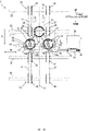
Fig. 3 is a front view illustrating the centeringmechanism 1.Fig. 4 is a front side perspective view illustrating the centeringmechanism 1.Fig. 5 is a rear side perspective view illustrating the centeringmechanism 1.Fig. 6 is a cross-sectional view taken along a line VI-VI inFig. 3 . - Here, as described above, the centering
mechanism 1 conveys the bank bills B in both directions from thedetermination unit 112 to the conveyance unit 113 (refer toFigs. 2A and2C ), and from theconveyance unit 113 to the determination unit 112 (refer toFig. 2B ). The description will be given assuming thatFigs. 3 to 6 andFigs. 7A to 7C to be described later illustrate a conveyance direction D set when a centeringunit 10 centers the position of the bank bill B in a width direction W orthogonal to the conveyance direction D, and a conveyance unit on an upstream side in the conveyance direction D is an upstreamside conveyance unit 20 and a conveyance unit on a downstream side is a downstreamside conveyance unit 30. Note that, in a case where directions in which the centeringunit 10 centers the position of the bank bill B in the width direction W include both forward and backward directions of the conveyance direction D, the upstreamside conveyance unit 20 functions not only as an upstream side conveyance unit but also as a downstream side conveyance unit, and the downstreamside conveyance unit 30 functions not only as a downstream side conveyance unit and but also as an upstream side conveyance unit. - As illustrated in
Figs. 3 to 6 , the centeringmechanism 1 includes two centeringunits side conveyance unit 20, the downstreamside conveyance unit 30, an arm 40 (an example of a first power transmission unit), adrive unit 50, a crown gear 61 (an example of a fourth gear), twopower transmission belts 62 and 62 (an example of second power transmission units), and anentry detection sensor 70. - The two centering
units units 10 may be one or plural number, but is desirably set to two. Each of the two centeringunits units - Each of the two centering
units conveyance roller 11, aball roller 12, arotational shaft 13, a spur gear 14 (an example of a first gear), a crown gear 15 (an example of a second gear), and asupport portion 16. - As illustrated in
Figs. 3 and4 , theconveyance roller 11 and theball roller 12 face each other in the front-back direction, and convey the bank bill B while pinching the bank bill B at pinch pressure P1 (refer toFig. 6 ). Note that the pinch pressure can be adjusted based on urging force (pressing force) of an elastic member pressing at least one of mutually-facing two conveyance members (rollers or belts) against the bank bill B. In addition, the pinch pressure can also be adjusted based on an inter-axial distance of mutually-facing two conveyance members, or tensile force of a belt (conveyance member). - The
rotational shaft 13 rotates integrally with theconveyance roller 11. Note that the rotation means being rotatable in both forward and backward directions. - The
spur gear 14 is provided on therotational shaft 13. - The
crown gear 15 includes teeth provided on the front side, and engages with thespur gear 14. Being driven by thedrive unit 50 to be described later, thecrown gear 15 rotates around a swing center (front-back direction) around which the centeringunit 10 swings. By thecrown gear 15 rotating based on power transmitted from the upstreamside conveyance unit 20, thespur gear 14 engaging with thecrown gear 15, and therotational shaft 13 and theconveyance roller 11 that rotate together with thespur gear 14 rotate, which will be described in detail later. In other words, theconveyance roller 11 rotates based on power transmitted from the upstreamside conveyance unit 20. - As illustrated in
Figs. 4 and5 , thesupport portion 16 has a U-shape opened toward the front side, and rotatably supports both ends of therotational shaft 13. - As illustrated in
Figs. 3 and4 , thesupport portion 16 includes anextension portion 16a protruding downward, and anelongated hole 16b provided in theextension portion 16a. Theelongated hole 16b is elongated in the conveyance direction D than in the width direction W, and provided in such a manner as to penetrate through theextension portion 16a in the front-back direction. In addition, apin 42 of thearm 40 to be described later is inserted into theelongated hole 16b. - The upstream
side conveyance unit 20 includes twoconveyance belts conveyance rollers 22, tworotational shafts 23, fourpulleys 24, and a spur gear 25 (an example of a third gear). - The two
conveyance belts conveyance belts 21 can be set to an arbitrary number equal to or larger than 1. Each of the twoconveyance belts pulleys - The four
conveyance rollers 22 are arranged in such a manner as to face therespective pulleys 24. The twoconveyance belts 21 and the fourconveyance rollers 22 face each other in the front-back direction, and convey the bank bill B while pinching the bank bill B at pinch pressure P2 (refer toFig. 6 ). The pinch pressure P2 is weaker than the pinch pressure P1 generated by theconveyance roller 11 and the ball roller 12 (P2 < P1). Note that the upstreamside conveyance unit 20 delivers the bank bill B to the centeringunit 10 in a state in which the centeringunit 10 pinches the bank bill B. In other words, the upstreamside conveyance unit 20 is arranged in such a manner as to neighbor the centeringunit 10 at an interval shorter than the length of the bank bill B in the conveyance direction D. - The two
rotational shafts 23 extend in the width direction W, and are arrayed at an interval in the conveyance direction D. - The two of the four
pulleys 24 are provided on each of therotational shafts 23, and thepulleys 24 rotate integrally with therotational shafts 23. - The
spur gear 25 is provided on arotational shaft 23 on the centeringunit 10 side (lower side), and rotates integrally with therotational shaft 23. Note that thespur gear 25 may be provided on arotational shaft 33 of the downstreamside conveyance unit 30. In this case, thecrown gear 61 and the twopower transmission belts side conveyance unit 20 side but on the downstreamside conveyance unit 30 side. - The downstream
side conveyance unit 30 includes twoconveyance belts conveyance rollers 32, tworotational shafts 33, and fourpulleys 34. - The two
conveyance belts conveyance belts 31 can be set to an arbitrary number equal to or larger than 1. Each of the twoconveyance belts pulleys - The four
conveyance rollers 32 are arranged in such a manner as to face therespective pulleys 34. The twoconveyance belts 31 and the fourconveyance rollers 32 face each other in the front-back direction, and convey the bank bill B while pinching the bank bill B at pinch pressure P3 (refer toFig. 6 ). The pinch pressure P3 is stronger than the pinch pressure P1 generated by theconveyance roller 11 and the ball roller 12 (P3 > P1). Thus, the pinch pressures P1 to P3 satisfy relationship of P3 > P1 > P2. Note that the bank bill B is delivered to the downstreamside conveyance unit 30 from the centeringunit 10 in a state in which the centeringunit 10 pinches the bank bill B. In other words, the downstreamside conveyance unit 30 is arranged in such a manner as to neighbor the centeringunit 10 at an interval shorter than the length of the bank bill B in the conveyance direction D. - The two
rotational shafts 33 extend in the width direction W, and are arrayed at an interval in the conveyance direction D. - The two of the four
pulleys 34 are provided on each of therotational shafts 33, and thepulleys 34 rotate integrally with therotational shafts 33. - The
arm 40 extends in the widthdirection W. Teeth 41 engaging with aspur gear 51 provided on an output shaft of thedrive unit 50 to be described later are provided on the front surface of a right end (an example of one end) of thearm 40. - In addition, two
pins holes support portions arm 40 integrally, for example, in such a manner as to protrude forward. - The
drive unit 50 is a motor, for example, that rotates thespur gear 51 provided on the output shaft extending in the conveyance direction D. By rotating thespur gear 51, thedrive unit 50 moves, in the width direction W, thearm 40 including theteeth 41 engaging with thespur gear 51. The support portion 16 (the centering unit 10) including theelongated hole 16b into which thepin 42 of thearm 40 is to be inserted thereby swings in such a manner as to incline with respect to the conveyance direction D around a swing center corresponding to the front-back direction. - As illustrated in
Fig. 5 , thecrown gear 61 includes teeth provided on the front side, engages with thespur gear 25 of the upstreamside conveyance unit 20, and rotates around a rotational center (front-back direction) parallel to the swing center of the centeringunit 10. - The two
power transmission belts 62 connect thecrown gear 61 and the two crown gears 15 by being stretched around a rotational shaft of thecrown gear 61 and rotational shafts of the two crown gears 15. - The
entry detection sensor 70 illustrated inFigs. 3 and4 detects the entry of the bank bill B into the centeringmechanism 1. As an example, theentry detection sensor 70 includes a light emitting unit that emits detection light forward, a prism that bends detection light emitted by the light emitting unit, in the width direction W and backward, and a light receiving unit that receives detection light bent backward by the prism. - Next, centering of the bank bill B using the centering
mechanism 1 will be described. -
Figs. 7A to 7C are front views for describing centering of the bank bill B. - Note that, in
Figs. 7A to 7C , the illustration of components (part of theball roller 12, the fourconveyance rollers 22, the fourconveyance rollers 32, and the entry detection sensor 70) provided on the front side of the bank bill B is omitted. - As illustrated in
Fig. 7A , first of all, the upstreamside conveyance unit 20 and the downstreamside conveyance unit 30 convey the bank bill B by rotating two pairs ofpulleys pulleys conveyance belts conveyance belts rotational shafts rotational shafts spur gear 25, thecrown gear 61, the twopower transmission belts spur gears rotational shafts rotational shafts 23 of the upstreamside conveyance unit 20, the twoconveyance rollers 11 rotate. The two centeringunits 10 thereby convey the bank bill B as well. - Here, as illustrated in
Fig. 7A , for example, a case where theentry detection sensor 70 detects the bank bill B detected by thedetermination unit 112 to have a center slanted toward the left side in the width direction W over the center C of the conveyance path will be considered. Note that, as a slant detection sensor for detecting that the center of the bank bill B is slanted toward either side in the width direction W over the center C, a line sensor, an imaging unit, or the like that is arranged on an upstream side in the conveyance direction D of the centeringmechanism 1 may be arranged aside from thedetermination unit 112. - In this case, for matching the center of the bank bill B in the width direction W with the center C of the conveyance path by moving the bank bill B toward the right side, as illustrated in
Fig. 7B , thedrive unit 50 rotates thespur gear 51 in such a manner as to move thearm 40 in the right direction. - With this configuration, by the two
support portions elongated holes pins arm 40 are to be inserted, rotating counterclockwise inFig. 7B , the entire centeringunits 10 rotate counterclockwise inFig. 7B , and incline with respect to the conveyance direction D. - Note that, as described above, because the pinch pressure P1 of the centering
unit 10 is stronger than the pinch pressure P2 of the upstreamside conveyance unit 20, if the centeringunit 10 inclines with respect to the conveyance direction D, the bank bill B is conveyed with inclination with respect to the conveyance direction D in accordance with the inclination of the centeringunit 10. - Thus, as illustrated in
Fig. 7C , the bank bill B is centered in such a manner that the center in the width direction W matches the center C of the conveyance path. - The centering
unit 10 that has performed centering of the bank bill B returns to the original position before the next bank bill B is conveyed. More specifically, thedrive unit 50 rotates thespur gear 51 in such a manner as to move thearm 40 in the left direction, and rotates the twosupport portions Fig. 7C . - In the present embodiment described above, the centering
mechanism 1 and theautomatic dealing apparatus 100 serving as an example of a paper sheet handling apparatus including the centeringmechanism 1 include the centeringunit 10, the upstreamside conveyance unit 20, and the downstreamside conveyance unit 30. The centeringunit 10 conveys the bank bill B in a pinched state, and centers the position of the bank bill B in the width direction W orthogonal to the conveyance direction D of the bank bill B by inclining with respect to the conveyance direction D. The upstreamside conveyance unit 20 is arranged on the upstream side of the centeringunit 10 in the conveyance direction D set when the centeringunit 10 centers the position of the bank bill B in the width direction W, and conveys the bank bill B. The downstreamside conveyance unit 30 is arranged on the downstream side of the centeringunit 10 in the conveyance direction D set when the centeringunit 10 centers the position of the bank bill B in the width direction W, and conveys the bank bill B in a pinched state In addition, the bank bill B is delivered to the downstreamside conveyance unit 30 from the centeringunit 10 in a state in which the centeringunit 10 pinches the bank bill B, and the downstreamside conveyance unit 30 conveys the bank bill B while pinching the bank bill B at the pinch pressure P3 (> pinch pressure P1) stronger than the pinch pressure at which the centeringunit 10 pinches the bank bill B. - In this manner, by the centering
unit 10 centering the position of the bank bill B in the width direction W while inclining with respect to the conveyance direction D, the occurrence of skew in the bank bill B can be suppressed as compared with the configuration of centering the position of the bank bill B in the width direction W by the centeringunit 10 linearly moving in the width direction W. - Meanwhile, in a case where the centering
unit 10 performs centering of the bank bill B by inclining with respect to the conveyance direction D, an amount of movement in the width direction of the bank bill B that is caused by centering depends on the length of the bank bill B in the conveyance direction D. Nevertheless, in the present embodiment, the bank bill B is delivered to the downstreamside conveyance unit 30 from the centeringunit 10 in a state in which the centeringunit 10 pinches the bank bill B, and the downstreamside conveyance unit 30 conveys the bank bill B while pinching the bank bill B at the pinch pressure P3 (> pinch pressure P1) stronger than the pinch pressure at which the centeringunit 10 pinches the bank bill B. Thus, if the leading end of the bank bill B reaches the downstreamside conveyance unit 30, the bank bill B is conveyed in the conveyance direction D irrespective of the inclination of the centeringunit 10. Thus, a conveyance distance required for centering the bank bill B in the width direction W (length required for the leading end of the bank bill B reaching the downstreamside conveyance unit 30 since the leading end reaches the centering unit 10) can be made constant irrespective of the length of the bank bill B in the conveyance direction D. Furthermore, by the downstreamside conveyance unit 30 conveying the bank bill B while pinching the bank bill B at the pinch pressure P3 (> pinch pressure P1) stronger than that of the centeringunit 10, the occurrence of retention of the bank bill B can be suppressed as compared with a configuration of using a conveyance unit that conveys the bank bill B while pinching the bank bill B at pinch pressure weaker than that of the centeringunit 10 over a region including the upstream side and the downstream side in the conveyance direction D of the centeringunit 10. - As described above, according to the present embodiment, centering of the bank bill B can be performed while surely conveying the bank bill B.
- In addition, in the present embodiment, the bank bill B is delivered to the centering
unit 10 from the upstreamside conveyance unit 20 in a state in which the upstreamside conveyance unit 20 pinches the bank bill B, and the centeringunit 10 conveys the bank bill B while pinching the bank bill B at the pinch pressure P1 (> pinch pressure P2) stronger than the pinch pressure at which the upstreamside conveyance unit 20 pinches the bank bill B. - With this configuration, as soon as the bank bill B is delivered to the centering
unit 10 from the upstreamside conveyance unit 20, centering of the bank bill B is performed by the inclination of the centeringunit 10 with respect to the conveyance direction D. Thus, a start timing of centering of the bank bill B can be made constant. The centering of the bank bill B can be accordingly performed more accurately. - In addition, in the present embodiment, the centering
mechanism 1 and theautomatic dealing apparatus 100 include two (an example of plural number) centeringunits units drive unit 50 that swings the two centeringunits arm 40 in the width direction W. - With this configuration, the two centering
units - In addition, in the present embodiment, the centering mechanism 1 and the automatic dealing apparatus 100 include two (an example of plural number) centering units 10 and 10 arrayed in the width direction W, and each of these two centering units 10 and 10 includes the conveyance roller 11, the spur gear 14 (an example of a first gear) provided on the rotational shaft 13 of the conveyance roller 11, and the crown gear 15 (an example of a second gear) that engages with the spur gear 14, and rotates around a swing center (front-back direction) around which the centering unit 10 swings in such a manner as to incline with respect to the conveyance direction D. In addition, the centering mechanism 1 and the automatic dealing apparatus 100 include the spur gear 25 (an example of a third gear) provided on the rotational shaft 23 of the upstream side conveyance unit 20 (an example of the upstream side conveyance unit 20 or the downstream side conveyance unit 30), the crown gear 61 (an example of a fourth gear) that engages with the spur gear 25, and rotates around a rotational center (front-back direction) parallel to the swing center of the centering unit 10, and the two power transmission belts 62 and 62 (an example of a plurality of second power transmission units) connected to the crown gear 61 and two (an example of plural number) crown gears 15 and 15.
- With this configuration, because the rotational center of the
crown gear 15 remains constant even if the centeringunit 10 swings, the two crown gears 15 and 15 and thecrown gear 61 can be stably connected. Thus, power for rotating theconveyance roller 11 can be transmitted from the upstreamside conveyance unit 20 to the swinging centeringunit 10 via thecrown gear 61 and the twopower transmission belts - Note that the present invention is not limited to an original configuration of the above-described embodiment, and can be embodied by modifying components. For example, various inventions can be formed by appropriately combining a plurality of components disclosed in the present embodiment. Various modifications of the invention and applications can be made without departing from the spirit of the invention.
-
- 1
- Centering mechanism
- 10
- Centering unit
- 11
- Conveyance roller
- 12
- Ball roller
- 13
- Rotational shaft
- 14
- Spur gear (first gear)
- 15
- Crown gear (second gear)
- 16
- Support portion
- 16a
- Extension portion
- 16b
- Elongated hole
- 20
- Upstream side conveyance unit
- 21
- Conveyance belt
- 22
- Conveyance roller
- 23
- Rotational shaft
- 24
- Pulley
- 25
- Spur gear (third gear)
- 30
- Downstream side conveyance unit
- 31
- Conveyance belt
- 32
- Conveyance roller
- 33
- Rotational shaft
- 34
- Pulley
- 40
- Arm (first power transmission unit)
- 41
- Tooth
- 42
- Pin
- 50
- Drive unit
- 51
- Spur gear
- 61
- Crown gear (fourth gear)
- 62
- Power transmission belt (second power transmission unit)
- 70
- Entry detection sensor
- 100
- Automatic dealing apparatus
- 110
- Main body unit
- 111
- Conveyance unit
- 112
- Determination unit
- 113
- Conveyance unit
- 114
- Temporary retention unit
- 115
- Reject unit
- 116
- Bank bill deposit/withdrawal unit
- 116a
- Front panel
- 116b
- Inlet/outlet port
- 116c
- Shutter
- 120
- Intermediate conveyance unit
- 130
- Storage unit
- 131 to
- 135 Bank bill storage cassette
- 136
- Storage conveyance unit
- B
- Bank bill
- C
- Center
- D
- Conveyance direction
- P1 to
- P3 Pinch pressure
- R1 to
- R4 Conveyance path
- W
- Width direction
Claims (5)
- A centering mechanism comprising:a centering unit configured to convey a paper sheet in a pinched state, and center a position of the paper sheet in a width direction orthogonal to a conveyance direction of the paper sheet by inclining with respect to the conveyance direction;an upstream side conveyance unit that is arranged on an upstream side of the centering unit in the conveyance direction set when the centering unit centers a position of the paper sheet in the width direction, and is configured to convey the paper sheet; anda downstream side conveyance unit that is arranged on a downstream side of the centering unit in the conveyance direction set when the centering unit centers a position of the paper sheet in the width direction, and is configured to convey the paper sheet in a pinched state,wherein the paper sheet is delivered to the downstream side conveyance unit from the centering unit in a state in which the centering unit pinches the paper sheet, and the downstream side conveyance unit conveys the paper sheet while pinching the paper sheet at pinch pressure stronger than pinch pressure at which the centering unit pinches the paper sheet.
- The centering mechanism according to claim 1,
wherein the paper sheet is delivered to the centering unit from the upstream side conveyance unit in a state in which the upstream side conveyance unit pinches the paper sheet, and the centering unit conveys the paper sheet while pinching the paper sheet at pinch pressure stronger than pinch pressure at which the upstream side conveyance unit pinches the paper sheet. - The centering mechanism according to claim 1 or 2, comprising:a plurality of the centering units arrayed in the width direction;a first power transmission unit configured to swingably support the plurality of centering units in such a manner as to incline with respect to the conveyance direction; anda drive unit configured to swing the plurality of centering units by moving the first power transmission unit in the width direction.
- The centering mechanism according to claim 1 or 2, comprising:a plurality of the centering units arrayed in the width direction,wherein each of the plurality of centering units includes:a conveyance roller;a first gear provided on a rotational shaft of the conveyance roller; anda second gear configured to engage with the first gear, and rotate around a swing center around which the centering unit swings in such a manner as to incline with respect to the conveyance direction, andwherein the centering mechanism includes:a third gear provided on a rotational shaft of the upstream side conveyance unit or the downstream side conveyance unit;a fourth gear configured to engage with the third gear, and rotate around a rotational center parallel to the swing center of the centering unit; anda plurality of second power transmission units connected to the fourth gear and a plurality of the second gears.
- A paper sheet handling apparatus comprising:a centering unit configured to convey a paper sheet in a pinched state, and center a position of the paper sheet in a width direction orthogonal to a conveyance direction of the paper sheet by inclining with respect to the conveyance direction;an upstream side conveyance unit that is arranged on an upstream side of the centering unit in the conveyance direction set when the centering unit centers a position of the paper sheet in the width direction, and is configured to convey the paper sheet; anda downstream side conveyance unit that is arranged on a downstream side of the centering unit in the conveyance direction set when the centering unit centers a position of the paper sheet in the width direction, and is configured to convey the paper sheet in a pinched state,wherein the paper sheet is delivered to the downstream side conveyance unit from the centering unit in a state in which the centering unit pinches the paper sheet, and the downstream side conveyance unit conveys the paper sheet while pinching the paper sheet at pinch pressure stronger than pinch pressure at which the centering unit pinches the paper sheet.
Applications Claiming Priority (1)
| Application Number | Priority Date | Filing Date | Title |
|---|---|---|---|
| PCT/JP2020/010577 WO2021181567A1 (en) | 2020-03-11 | 2020-03-11 | Centering mechanism and paper-sheet handling device |
Publications (3)
| Publication Number | Publication Date |
|---|---|
| EP4119474A1 true EP4119474A1 (en) | 2023-01-18 |
| EP4119474A4 EP4119474A4 (en) | 2023-12-13 |
| EP4119474B1 EP4119474B1 (en) | 2025-01-29 |
Family
ID=77670931
Family Applications (1)
| Application Number | Title | Priority Date | Filing Date |
|---|---|---|---|
| EP20923817.9A Active EP4119474B1 (en) | 2020-03-11 | 2020-03-11 | Centering mechanism and paper-sheet handling device |
Country Status (5)
| Country | Link |
|---|---|
| US (1) | US12172864B2 (en) |
| EP (1) | EP4119474B1 (en) |
| JP (1) | JP7240556B2 (en) |
| CN (1) | CN115243989A (en) |
| WO (1) | WO2021181567A1 (en) |
Family Cites Families (14)
| Publication number | Priority date | Publication date | Assignee | Title |
|---|---|---|---|---|
| JPH07149455A (en) | 1993-11-30 | 1995-06-13 | Kofu Nippon Denki Kk | Paper sheet insert mechanism |
| US5697609A (en) * | 1996-06-26 | 1997-12-16 | Xerox Corporation | Lateral sheet pre-registration device |
| JP5178800B2 (en) * | 2010-10-15 | 2013-04-10 | キヤノン株式会社 | Sheet conveying apparatus and image forming apparatus |
| US8348267B2 (en) * | 2011-02-18 | 2013-01-08 | Xerox Corporation | Media rotation and translation apparatus |
| JP5608814B2 (en) * | 2011-05-25 | 2014-10-15 | 株式会社マースウインテック | Paper sheet identification device |
| US8469358B1 (en) * | 2012-04-05 | 2013-06-25 | Delphax Technologies Inc. | Registration and transport unit for a sheet feeder |
| JP2014069896A (en) * | 2012-09-27 | 2014-04-21 | Toshiba Corp | Attitude correction device |
| JP2015016956A (en) * | 2013-07-10 | 2015-01-29 | 株式会社リコー | Sheet conveying apparatus and image forming apparatus |
| JP2015099425A (en) | 2013-11-18 | 2015-05-28 | 株式会社日本コンラックス | Paper money processing device |
| KR101681503B1 (en) * | 2014-10-08 | 2016-12-01 | 노틸러스효성 주식회사 | Apparatus for automatical alignment and unit for adjusting skewness |
| DE102017105842B4 (en) * | 2017-03-17 | 2019-05-29 | Wincor Nixdorf International Gmbh | Device for aligning notes of value |
| EP3492411B1 (en) * | 2017-11-29 | 2024-02-14 | Ricoh Company, Ltd. | Sheet conveying device and image forming apparatus incorporating the sheet conveying device |
| JP6971862B2 (en) * | 2018-01-10 | 2021-11-24 | 日立チャネルソリューションズ株式会社 | Paper leaf handling device, automated teller machine and paper leaf handling method |
| US10584009B1 (en) * | 2019-08-02 | 2020-03-10 | Capital One Services, Llc | Sheet orienting apparatus using ball drive |
-
2020
- 2020-03-11 JP JP2022507083A patent/JP7240556B2/en active Active
- 2020-03-11 WO PCT/JP2020/010577 patent/WO2021181567A1/en not_active Ceased
- 2020-03-11 EP EP20923817.9A patent/EP4119474B1/en active Active
- 2020-03-11 CN CN202080098281.2A patent/CN115243989A/en active Pending
-
2022
- 2022-09-07 US US17/930,209 patent/US12172864B2/en active Active
Also Published As
| Publication number | Publication date |
|---|---|
| US20220411214A1 (en) | 2022-12-29 |
| EP4119474B1 (en) | 2025-01-29 |
| WO2021181567A1 (en) | 2021-09-16 |
| CN115243989A (en) | 2022-10-25 |
| EP4119474A4 (en) | 2023-12-13 |
| JPWO2021181567A1 (en) | 2021-09-16 |
| JP7240556B2 (en) | 2023-03-15 |
| US12172864B2 (en) | 2024-12-24 |
Similar Documents
| Publication | Publication Date | Title |
|---|---|---|
| US7422095B2 (en) | Bill handling device and bill accommodating unit | |
| US7806396B2 (en) | Sheet handling apparatus | |
| US20110198192A1 (en) | Medium processing apparatus | |
| JP3846695B2 (en) | Banknote automatic transaction device | |
| JP2002197507A (en) | Bill validator and bill automatic transaction device equipped with the bill validator | |
| CN1776749B (en) | Bill handling machine and bill storage unit | |
| JP4261078B2 (en) | Bill discriminating device with bill center aligning device | |
| KR100212932B1 (en) | Bill handling machine | |
| US20100270120A1 (en) | Paper sheet processing device | |
| US12172864B2 (en) | Centering mechanism and paper sheet handling apparatus | |
| EP3567559A1 (en) | Value note cassette | |
| JP5226869B2 (en) | Bundle conveying device and paper sheet handling device | |
| JP6515501B2 (en) | Paper sheet identification device | |
| WO2019174519A1 (en) | Sheet-type medium conveying apparatus and bill recycling device | |
| CN103548061B (en) | paper identification device | |
| US20100289212A1 (en) | Device for processing paper sheets or the like | |
| JP4835194B2 (en) | Banknote handling equipment | |
| GB2402801A (en) | Bank-note authentication apparatus accommodating notes of different widths | |
| JPH11134469A (en) | Paper counting machine | |
| JP2756538B2 (en) | Sheet processing equipment | |
| JP2624530B2 (en) | Paper transport device | |
| WO2019016964A1 (en) | Paper sheet transporting device, paper sheet handling device, and paper sheet transporting method | |
| JP3545242B2 (en) | Stacked bill transporter | |
| JP3445182B2 (en) | Banknote handling machine | |
| JPH10181926A (en) | Note processing machine |
Legal Events
| Date | Code | Title | Description |
|---|---|---|---|
| STAA | Information on the status of an ep patent application or granted ep patent |
Free format text: STATUS: THE INTERNATIONAL PUBLICATION HAS BEEN MADE |
|
| PUAI | Public reference made under article 153(3) epc to a published international application that has entered the european phase |
Free format text: ORIGINAL CODE: 0009012 |
|
| STAA | Information on the status of an ep patent application or granted ep patent |
Free format text: STATUS: REQUEST FOR EXAMINATION WAS MADE |
|
| 17P | Request for examination filed |
Effective date: 20220915 |
|
| AK | Designated contracting states |
Kind code of ref document: A1 Designated state(s): AL AT BE BG CH CY CZ DE DK EE ES FI FR GB GR HR HU IE IS IT LI LT LU LV MC MK MT NL NO PL PT RO RS SE SI SK SM TR |
|
| DAV | Request for validation of the european patent (deleted) | ||
| DAX | Request for extension of the european patent (deleted) | ||
| A4 | Supplementary search report drawn up and despatched |
Effective date: 20231109 |
|
| RIC1 | Information provided on ipc code assigned before grant |
Ipc: B65H 5/02 20060101ALI20231103BHEP Ipc: G07D 11/17 20190101ALI20231103BHEP Ipc: B65H 9/16 20060101ALI20231103BHEP Ipc: B65H 9/00 20060101AFI20231103BHEP |
|
| GRAP | Despatch of communication of intention to grant a patent |
Free format text: ORIGINAL CODE: EPIDOSNIGR1 |
|
| STAA | Information on the status of an ep patent application or granted ep patent |
Free format text: STATUS: GRANT OF PATENT IS INTENDED |
|
| INTG | Intention to grant announced |
Effective date: 20240910 |
|
| RIC1 | Information provided on ipc code assigned before grant |
Ipc: B65H 5/02 20060101ALI20240830BHEP Ipc: G07D 11/17 20190101ALI20240830BHEP Ipc: B65H 9/16 20060101ALI20240830BHEP Ipc: B65H 9/00 20060101AFI20240830BHEP |
|
| GRAS | Grant fee paid |
Free format text: ORIGINAL CODE: EPIDOSNIGR3 |
|
| GRAA | (expected) grant |
Free format text: ORIGINAL CODE: 0009210 |
|
| STAA | Information on the status of an ep patent application or granted ep patent |
Free format text: STATUS: THE PATENT HAS BEEN GRANTED |
|
| AK | Designated contracting states |
Kind code of ref document: B1 Designated state(s): AL AT BE BG CH CY CZ DE DK EE ES FI FR GB GR HR HU IE IS IT LI LT LU LV MC MK MT NL NO PL PT RO RS SE SI SK SM TR |
|
| REG | Reference to a national code |
Ref country code: GB Ref legal event code: FG4D |
|
| REG | Reference to a national code |
Ref country code: CH Ref legal event code: EP |
|
| REG | Reference to a national code |
Ref country code: DE Ref legal event code: R096 Ref document number: 602020045681 Country of ref document: DE |
|
| REG | Reference to a national code |
Ref country code: IE Ref legal event code: FG4D |
|
| REG | Reference to a national code |
Ref country code: NL Ref legal event code: MP Effective date: 20250129 |
|
| PG25 | Lapsed in a contracting state [announced via postgrant information from national office to epo] |
Ref country code: NL Free format text: LAPSE BECAUSE OF FAILURE TO SUBMIT A TRANSLATION OF THE DESCRIPTION OR TO PAY THE FEE WITHIN THE PRESCRIBED TIME-LIMIT Effective date: 20250129 |
|
| PG25 | Lapsed in a contracting state [announced via postgrant information from national office to epo] |
Ref country code: RS Free format text: LAPSE BECAUSE OF FAILURE TO SUBMIT A TRANSLATION OF THE DESCRIPTION OR TO PAY THE FEE WITHIN THE PRESCRIBED TIME-LIMIT Effective date: 20250429 |
|
| PG25 | Lapsed in a contracting state [announced via postgrant information from national office to epo] |
Ref country code: FI Free format text: LAPSE BECAUSE OF FAILURE TO SUBMIT A TRANSLATION OF THE DESCRIPTION OR TO PAY THE FEE WITHIN THE PRESCRIBED TIME-LIMIT Effective date: 20250129 |
|
| PG25 | Lapsed in a contracting state [announced via postgrant information from national office to epo] |
Ref country code: PL Free format text: LAPSE BECAUSE OF FAILURE TO SUBMIT A TRANSLATION OF THE DESCRIPTION OR TO PAY THE FEE WITHIN THE PRESCRIBED TIME-LIMIT Effective date: 20250129 |
|
| PG25 | Lapsed in a contracting state [announced via postgrant information from national office to epo] |
Ref country code: ES Free format text: LAPSE BECAUSE OF FAILURE TO SUBMIT A TRANSLATION OF THE DESCRIPTION OR TO PAY THE FEE WITHIN THE PRESCRIBED TIME-LIMIT Effective date: 20250129 |
|
| REG | Reference to a national code |
Ref country code: LT Ref legal event code: MG9D |
|
| PG25 | Lapsed in a contracting state [announced via postgrant information from national office to epo] |
Ref country code: IS Free format text: LAPSE BECAUSE OF FAILURE TO SUBMIT A TRANSLATION OF THE DESCRIPTION OR TO PAY THE FEE WITHIN THE PRESCRIBED TIME-LIMIT Effective date: 20250529 Ref country code: NO Free format text: LAPSE BECAUSE OF FAILURE TO SUBMIT A TRANSLATION OF THE DESCRIPTION OR TO PAY THE FEE WITHIN THE PRESCRIBED TIME-LIMIT Effective date: 20250429 |
|
| REG | Reference to a national code |
Ref country code: AT Ref legal event code: MK05 Ref document number: 1763300 Country of ref document: AT Kind code of ref document: T Effective date: 20250129 |
|
| PG25 | Lapsed in a contracting state [announced via postgrant information from national office to epo] |
Ref country code: HR Free format text: LAPSE BECAUSE OF FAILURE TO SUBMIT A TRANSLATION OF THE DESCRIPTION OR TO PAY THE FEE WITHIN THE PRESCRIBED TIME-LIMIT Effective date: 20250129 |
|
| PG25 | Lapsed in a contracting state [announced via postgrant information from national office to epo] |
Ref country code: LV Free format text: LAPSE BECAUSE OF FAILURE TO SUBMIT A TRANSLATION OF THE DESCRIPTION OR TO PAY THE FEE WITHIN THE PRESCRIBED TIME-LIMIT Effective date: 20250129 Ref country code: PT Free format text: LAPSE BECAUSE OF FAILURE TO SUBMIT A TRANSLATION OF THE DESCRIPTION OR TO PAY THE FEE WITHIN THE PRESCRIBED TIME-LIMIT Effective date: 20250529 |
|
| PG25 | Lapsed in a contracting state [announced via postgrant information from national office to epo] |
Ref country code: GR Free format text: LAPSE BECAUSE OF FAILURE TO SUBMIT A TRANSLATION OF THE DESCRIPTION OR TO PAY THE FEE WITHIN THE PRESCRIBED TIME-LIMIT Effective date: 20250430 Ref country code: BG Free format text: LAPSE BECAUSE OF FAILURE TO SUBMIT A TRANSLATION OF THE DESCRIPTION OR TO PAY THE FEE WITHIN THE PRESCRIBED TIME-LIMIT Effective date: 20250129 |
|
| PG25 | Lapsed in a contracting state [announced via postgrant information from national office to epo] |
Ref country code: AT Free format text: LAPSE BECAUSE OF FAILURE TO SUBMIT A TRANSLATION OF THE DESCRIPTION OR TO PAY THE FEE WITHIN THE PRESCRIBED TIME-LIMIT Effective date: 20250129 |
|
| PG25 | Lapsed in a contracting state [announced via postgrant information from national office to epo] |
Ref country code: SE Free format text: LAPSE BECAUSE OF FAILURE TO SUBMIT A TRANSLATION OF THE DESCRIPTION OR TO PAY THE FEE WITHIN THE PRESCRIBED TIME-LIMIT Effective date: 20250129 |
|
| REG | Reference to a national code |
Ref country code: DE Ref legal event code: R119 Ref document number: 602020045681 Country of ref document: DE |
|
| PG25 | Lapsed in a contracting state [announced via postgrant information from national office to epo] |
Ref country code: SM Free format text: LAPSE BECAUSE OF FAILURE TO SUBMIT A TRANSLATION OF THE DESCRIPTION OR TO PAY THE FEE WITHIN THE PRESCRIBED TIME-LIMIT Effective date: 20250129 |
|
| PG25 | Lapsed in a contracting state [announced via postgrant information from national office to epo] |
Ref country code: DK Free format text: LAPSE BECAUSE OF FAILURE TO SUBMIT A TRANSLATION OF THE DESCRIPTION OR TO PAY THE FEE WITHIN THE PRESCRIBED TIME-LIMIT Effective date: 20250129 |
|
| PG25 | Lapsed in a contracting state [announced via postgrant information from national office to epo] |
Ref country code: MC Free format text: LAPSE BECAUSE OF FAILURE TO SUBMIT A TRANSLATION OF THE DESCRIPTION OR TO PAY THE FEE WITHIN THE PRESCRIBED TIME-LIMIT Effective date: 20250129 |
|
| PG25 | Lapsed in a contracting state [announced via postgrant information from national office to epo] |
Ref country code: IT Free format text: LAPSE BECAUSE OF FAILURE TO SUBMIT A TRANSLATION OF THE DESCRIPTION OR TO PAY THE FEE WITHIN THE PRESCRIBED TIME-LIMIT Effective date: 20250129 |
|
| PG25 | Lapsed in a contracting state [announced via postgrant information from national office to epo] |
Ref country code: CZ Free format text: LAPSE BECAUSE OF FAILURE TO SUBMIT A TRANSLATION OF THE DESCRIPTION OR TO PAY THE FEE WITHIN THE PRESCRIBED TIME-LIMIT Effective date: 20250129 Ref country code: EE Free format text: LAPSE BECAUSE OF FAILURE TO SUBMIT A TRANSLATION OF THE DESCRIPTION OR TO PAY THE FEE WITHIN THE PRESCRIBED TIME-LIMIT Effective date: 20250129 |
|
| PG25 | Lapsed in a contracting state [announced via postgrant information from national office to epo] |
Ref country code: RO Free format text: LAPSE BECAUSE OF FAILURE TO SUBMIT A TRANSLATION OF THE DESCRIPTION OR TO PAY THE FEE WITHIN THE PRESCRIBED TIME-LIMIT Effective date: 20250129 |
|
| REG | Reference to a national code |
Ref country code: CH Ref legal event code: H13 Free format text: ST27 STATUS EVENT CODE: U-0-0-H10-H13 (AS PROVIDED BY THE NATIONAL OFFICE) Effective date: 20251024 |
|
| PG25 | Lapsed in a contracting state [announced via postgrant information from national office to epo] |
Ref country code: SK Free format text: LAPSE BECAUSE OF FAILURE TO SUBMIT A TRANSLATION OF THE DESCRIPTION OR TO PAY THE FEE WITHIN THE PRESCRIBED TIME-LIMIT Effective date: 20250129 |
|
| PG25 | Lapsed in a contracting state [announced via postgrant information from national office to epo] |
Ref country code: LU Free format text: LAPSE BECAUSE OF NON-PAYMENT OF DUE FEES Effective date: 20250311 |
|
| PLBE | No opposition filed within time limit |
Free format text: ORIGINAL CODE: 0009261 |
|
| STAA | Information on the status of an ep patent application or granted ep patent |
Free format text: STATUS: NO OPPOSITION FILED WITHIN TIME LIMIT |
|
| REG | Reference to a national code |
Ref country code: BE Ref legal event code: MM Effective date: 20250331 |
|
| 26N | No opposition filed |
Effective date: 20251030 |
|
| PG25 | Lapsed in a contracting state [announced via postgrant information from national office to epo] |
Ref country code: DE Free format text: LAPSE BECAUSE OF NON-PAYMENT OF DUE FEES Effective date: 20251001 |
|
| PG25 | Lapsed in a contracting state [announced via postgrant information from national office to epo] |
Ref country code: FR Free format text: LAPSE BECAUSE OF NON-PAYMENT OF DUE FEES Effective date: 20250329 |
|
| PG25 | Lapsed in a contracting state [announced via postgrant information from national office to epo] |
Ref country code: BE Free format text: LAPSE BECAUSE OF NON-PAYMENT OF DUE FEES Effective date: 20250331 |
|
| PG25 | Lapsed in a contracting state [announced via postgrant information from national office to epo] |
Ref country code: CH Free format text: LAPSE BECAUSE OF NON-PAYMENT OF DUE FEES Effective date: 20250331 |
|
| PG25 | Lapsed in a contracting state [announced via postgrant information from national office to epo] |
Ref country code: IE Free format text: LAPSE BECAUSE OF NON-PAYMENT OF DUE FEES Effective date: 20250311 |
|
| PGFP | Annual fee paid to national office [announced via postgrant information from national office to epo] |
Ref country code: GB Payment date: 20260202 Year of fee payment: 7 |