EP4119003B1 - Einrichtungsgegenstand und dessen verwendung - Google Patents
Einrichtungsgegenstand und dessen verwendung Download PDFInfo
- Publication number
- EP4119003B1 EP4119003B1 EP21185908.7A EP21185908A EP4119003B1 EP 4119003 B1 EP4119003 B1 EP 4119003B1 EP 21185908 A EP21185908 A EP 21185908A EP 4119003 B1 EP4119003 B1 EP 4119003B1
- Authority
- EP
- European Patent Office
- Prior art keywords
- furnishing item
- head
- longitudinal groove
- framing
- slot
- Prior art date
- Legal status (The legal status is an assumption and is not a legal conclusion. Google has not performed a legal analysis and makes no representation as to the accuracy of the status listed.)
- Active
Links
Images


Classifications
-
- A—HUMAN NECESSITIES
- A47—FURNITURE; DOMESTIC ARTICLES OR APPLIANCES; COFFEE MILLS; SPICE MILLS; SUCTION CLEANERS IN GENERAL
- A47B—TABLES; DESKS; OFFICE FURNITURE; CABINETS; DRAWERS; GENERAL DETAILS OF FURNITURE
- A47B47/00—Cabinets, racks or shelf units, characterised by features related to dismountability or building-up from elements
- A47B47/02—Cabinets, racks or shelf units, characterised by features related to dismountability or building-up from elements made of metal only
- A47B47/03—Cabinets, racks or shelf units, characterised by features related to dismountability or building-up from elements made of metal only with panels separate from the frame
-
- A—HUMAN NECESSITIES
- A47—FURNITURE; DOMESTIC ARTICLES OR APPLIANCES; COFFEE MILLS; SPICE MILLS; SUCTION CLEANERS IN GENERAL
- A47B—TABLES; DESKS; OFFICE FURNITURE; CABINETS; DRAWERS; GENERAL DETAILS OF FURNITURE
- A47B47/00—Cabinets, racks or shelf units, characterised by features related to dismountability or building-up from elements
- A47B47/04—Cabinets, racks or shelf units, characterised by features related to dismountability or building-up from elements made mainly of wood or plastics
- A47B47/05—Cabinets, racks or shelf units, characterised by features related to dismountability or building-up from elements made mainly of wood or plastics with panels on a separate frame, e.g. a metal frame
-
- A—HUMAN NECESSITIES
- A47—FURNITURE; DOMESTIC ARTICLES OR APPLIANCES; COFFEE MILLS; SPICE MILLS; SUCTION CLEANERS IN GENERAL
- A47B—TABLES; DESKS; OFFICE FURNITURE; CABINETS; DRAWERS; GENERAL DETAILS OF FURNITURE
- A47B96/00—Details of cabinets, racks or shelf units not covered by a single one of groups A47B43/00 - A47B95/00; General details of furniture
- A47B96/06—Brackets or similar supporting means for cabinets, racks or shelves
- A47B96/067—Horizontal rails as suspension means in a cantilever arrangement
-
- A—HUMAN NECESSITIES
- A47—FURNITURE; DOMESTIC ARTICLES OR APPLIANCES; COFFEE MILLS; SPICE MILLS; SUCTION CLEANERS IN GENERAL
- A47B—TABLES; DESKS; OFFICE FURNITURE; CABINETS; DRAWERS; GENERAL DETAILS OF FURNITURE
- A47B96/00—Details of cabinets, racks or shelf units not covered by a single one of groups A47B43/00 - A47B95/00; General details of furniture
- A47B96/14—Bars, uprights, struts, or like supports, for cabinets, brackets, or the like
- A47B96/1466—Bars, uprights, struts, or like supports, for cabinets, brackets, or the like with longitudinal grooves
-
- E—FIXED CONSTRUCTIONS
- E04—BUILDING
- E04F—FINISHING WORK ON BUILDINGS, e.g. STAIRS, FLOORS
- E04F13/00—Coverings or linings, e.g. for walls or ceilings
- E04F13/07—Coverings or linings, e.g. for walls or ceilings composed of covering or lining elements; Sub-structures therefor; Fastening means therefor
- E04F13/08—Coverings or linings, e.g. for walls or ceilings composed of covering or lining elements; Sub-structures therefor; Fastening means therefor composed of a plurality of similar covering or lining elements
- E04F13/0801—Separate fastening elements
- E04F13/0832—Separate fastening elements without load-supporting elongated furring elements between wall and covering elements
- E04F13/0833—Separate fastening elements without load-supporting elongated furring elements between wall and covering elements not adjustable
- E04F13/0851—Hooking means on the back side of the covering elements
-
- F—MECHANICAL ENGINEERING; LIGHTING; HEATING; WEAPONS; BLASTING
- F16—ENGINEERING ELEMENTS AND UNITS; GENERAL MEASURES FOR PRODUCING AND MAINTAINING EFFECTIVE FUNCTIONING OF MACHINES OR INSTALLATIONS; THERMAL INSULATION IN GENERAL
- F16B—DEVICES FOR FASTENING OR SECURING CONSTRUCTIONAL ELEMENTS OR MACHINE PARTS TOGETHER, e.g. NAILS, BOLTS, CIRCLIPS, CLAMPS, CLIPS OR WEDGES; JOINTS OR JOINTING
- F16B12/00—Jointing of furniture or the like, e.g. hidden from exterior
- F16B12/10—Jointing of furniture or the like, e.g. hidden from exterior using pegs, bolts, tenons, clamps, clips, or the like
- F16B12/28—Jointing of furniture or the like, e.g. hidden from exterior using pegs, bolts, tenons, clamps, clips, or the like for metal furniture parts
- F16B12/32—Jointing of furniture or the like, e.g. hidden from exterior using pegs, bolts, tenons, clamps, clips, or the like for metal furniture parts using clamps, clips, wedges, sliding bolts, or the like
-
- A—HUMAN NECESSITIES
- A47—FURNITURE; DOMESTIC ARTICLES OR APPLIANCES; COFFEE MILLS; SPICE MILLS; SUCTION CLEANERS IN GENERAL
- A47B—TABLES; DESKS; OFFICE FURNITURE; CABINETS; DRAWERS; GENERAL DETAILS OF FURNITURE
- A47B2230/00—Furniture jointing; Furniture with such jointing
- A47B2230/0003—Adjustable furniture jointing
- A47B2230/0018—Screws or bolts sliding in sectional grooves
- A47B2230/0025—Screws or bolts sliding in sectional grooves with shoes in said grooves
Definitions
- the present invention concerns a furnishing item and the use of it, specifically according to the independent claims.
- Furnishing items or furnishings can be furniture.
- furniture refers to movable objects intended to support various human activities such as seating (e.g., chairs, stools, and sofas), eating (tables), and sleeping (e.g., beds). Furniture is also used to hold objects at a convenient height for work (as horizontal surfaces above the ground, such as tables and desks), or to store things (e.g., cupboards and shelves).
- furnishing items in the sense of the present invention may also be walls, e.g. built up like drywalls.
- the disadvantage of all the above-mentioned furniture concepts is the fact that the individual parts like side, bottom, back and top parts forming the corpus have to be assembled together in order to achieve stability. Another disadvantage is the fact that after the purchase a flexible extension or reduction of the furniture is not possible or only possible with a very high effort.
- a third disadvantage is the fact that the relevant decorations visible on the outside are usually not interchangeable, as they are part of the static whole corpus of the furniture.
- a fourth disadvantage comes into play when a part has to be replaced due to damage, which is not possible or only possible at very high cost with conventional furniture, especially if the furniture is older and not produced anymore.
- US 8 998 009 B2 and FR 1 480 683 A disclose a wall assembly for goods display constituted by horizontal tracks fixed to a wall body and disposed in a lateral direction at equal intervals, vertical posts disposed on the horizontal tracks and disposed in a vertical direction at equal intervals, an interval adjustment unit configured to couple the vertical post with respect to the horizontal track to adjust an interval, an insert member inserted into the vertical post in the vertical direction, and an outer panel coupled to the vertical post.
- a decorative panel can be attached to the at least one tracks and can be connected to the tracks and detached therefrom by means of a non-positive and/or positive connection, wherein the non-positive and/or positive connection has a first retaining element and a second retaining element of complementary design, wherein the first retaining element is connected to the rear side of the decorative panel in a substance-locking manner or is formed by the latter and the second retaining element is mounted on the tracks in a non-positive and/or positive manner or is formed by the latter.
- US 6 226 947 B1 discloses a cladding board mounting system for mounting cladding boards adjacent a surface to be concealed.
- Each cladding board includes at least one support member on the interior face of the cladding board.
- the system further includes at least one mounting member which includes an engaging formation adapted for releasable engagement with a complementary engaging formation of a respective support member.
- the mounting member also includes a second segment for releasable connection to the surface to be concealed.
- a mounting bracket extends between the surface to be clad and the mounting member.
- GB 2 505 011 A discloses a device for mounting shelves, panels, displays, pictures and the like on a wall or other vertical surface comprises a pair of identical battens or mounts forming a set. In use, one mount is fixed to a wall and one to the article to be hung such that the fixings are not visible from the front face of the article.
- US 2016/017595 A1 discloses a hexahedron unit for prefabricated buildings, comprising twelve frames, wherein two frames of adjoining units are fixedly connected by means of a frame joint, wherein the frame joint includes a planar frame joint body, two or more connectors vertically coupled to the frame joint body, and an insertion section connected to an end side of the connector, and wherein the frame includes an elongate bar-type frame body having a hollow rectangular sectional shape with a plurality of internal compartments divided by a plurality of partition walls, and a hollow insertion-space defined in the frame body in a shape corresponding to that of the insertion section of the frame joint body for fitting-engagement with the insertion section.
- a furnishing item according to the present invention comprises a corpus with at least one framing which is made from a plurality of structural profiles to form a frame, wherein a decorative panel can be attached to the at least one framing and can be connected to the framing and detached therefrom by means of a non-positive and/or positive connection, wherein the non-positive and/or positive connection has a first retaining element and a second retaining element of complementary design, wherein the first retaining element is connected to the rear side of the decorative panel in a substance-locking manner or is formed by the latter and the second retaining element is mounted on the framing in a non-positive and/or positive manner or is formed by the latter.
- the furnishing item By making the decorative panel detachable from the framing, the furnishing item has almost an unlimited lifespan. If in the course of time it will not anymore seem modern to the user due to its decors or colours or due to the location or living circumstances of the user, it can be interchanged. Due to the modular design of the furnishing item, it can be extended, reduced or completely redesigned with other materials, surfaces, colours and decors at any time. To extend a wardrobe, for example, all the user has to do is to provide another framing for the outer side, move the decorative panel to what is now the outer side, insert the desired objects such as a door or drawers and add or replace the top cover panel.
- a further advantage concerns the individualisation of the furnishing item of the present invention.
- the corpus defining the substructure of the furniture bears the load of the construction and the inner panelling of the furniture are always kept decoratively neutral. That means that the load bearing part of the corpus is independent of the decor part of the corpus.
- the outer decor can be replaced at any time, even after purchase. This offers the user the opportunity to customise his furniture and change it at any time.
- Top panels, doors, drawer fronts and side panels can be exchanged for other materials and decors as desired.
- the furnishing item according to the present invention is a product that is truly sustainable since it is made to have a very long life and, thus, avoid waste.
- Each individual part can be replaced by dismounting the decorative panel from the framing or the corpus.
- damaged parts can easily be interchanged for new ones, over and over again. If all individual parts of the furnishing item are made of extremely stable and high-quality components, the life cycle of this furniture is almost unlimited.
- the material-locking connection of the first retaining element to the decorative panel may be an adhesive connection, wherein preferably the adhesive of the adhesive connection is a polyurethane or a silyl modified polymer.
- the material-locking connection of the first retaining element to the decorative panel is an adhesive connection.
- the adhesive of the adhesive connection is a two-component adhesive, more preferably a two-component adhesive based on polyurethane, wherein preferably the polyurethane comprising methylene diphenyl diisocyanate (MDI) or hexamethylene diisocyanate (HDI) as isocyanate, the poyol being preferably an amino polyol.
- MDI methylene diphenyl diisocyanate
- HDI hexamethylene diisocyanate
- the adhesive can also be a one-component adhesive, preferably the adhesive is a one-component adhesive based on silyl modified polymer.
- the adhesive connection can be preferably carried out according to DIN 2304. In this way, particularly strong adhesive bonds can be achieved.
- the adhesive applied according to this invention is particularly UV-resistant and, therefore, especially suitable for outdoor use.
- the material-locking connection can be carried out to achieve a firm bond and be extremely cost-effective.
- the thickness of the decorative panel can be relatively thin, thus saving material.
- the advantages of the present invention can be at best attained if the tensile strength of the adhesive in the cured state, measured according to DIN EN ISO 527-1, ranges from 1 - 20 N/mm 2 , preferably from 1-15 N/mm 2 , and most preferably from 2 - 10 N/mm 2 .
- the elongation at break ranges from 10 - 400 %, preferably from 50 - 300 %, and most preferably from 150 - 250 %.
- the bending strength of bonded parts is at least 0.5 N/mm 2 , more preferably at least 1 N/mm 2 , even more preferably at least 2 N/mm 2 , whereby the bending strength of bonded parts is not more than 50 N/mm 2 , preferably not more than 20 N/mm 2 .
- the bending strength of bonded parts is from 0.5 to 50 N/mm 2 , preferably 1 to 20 N/mm 2 , more preferably from 1.5 to 15 N/mm 2 , even more preferably from 1.5 to 10 N/mm 2 , and most preferably from 1.5 to 5 N/mm 2 .
- the shear strength is from 1 to 15 N/mm 2 , preferably 1.5 to 10 N/mm 2 , and more preferably from 1.5 to 5 N/mm 2 .
- the tolerated exposure time to artificial weathering using fluorescent UV lamps and water measured according to DIN EN 927-6, is at least 500 hours, preferably at least 750 hours, and more preferably at least 1000 hours when using QUV-devices to imitate weathering.
- the structural profiles of the furnishing item are provided on one or more of their sides with at least one longitudinal groove, into which a complementarily formed slot nut can be introduced, wherein preferably the slot nut comprises at least one threaded bore (which is perpendicular with its longitudinal axis to the longitudinal axis of the structural profile) and into which a corresponding screw can be introduced in order to releasably clamp the slot nut within the longitudinal groove against the boundary surfaces thereof.
- the corpus i.e. the framing can be provided cost-optimized, since such standard parts like structural profiles and slot nuts are easily obtainable.
- the longitudinal grooves of the structural profiles may have a T-shape or a mushroom shape when viewed in a cross-section perpendicular to the longitudinal axis of the structural profile as can be found at conventional standardised structural profiles.
- the construction profiles may be formed from light materials, e.g. aluminium. In a cross-section, these can have a rectangular shape.
- correspondingly two part-slot nuts may be provided which are separably connectable to each other or are formed in one piece with each other.
- the one part-slot nut comprises a preferably rotationally symmetrical head, such as a mushroom head, and an adjoining shaft with a smaller external diameter than that of the head, and the head may be preferably designed in relation to the longitudinal groove in which it is guided in such a manner that it may be freely movable with play in the longitudinal groove along the longitudinal axis of the structural profile, but the play against tilting in the direction away from the longitudinal axis of the structural profile between the contact surfaces of the part-slot nut and the boundary surfaces of the longitudinal groove may be between 0.01 and 0.1 mm, in order to prevent jamming of the part-slot nut during displacement along the longitudinal axis of the structural profile.
- the part-slot nut comprises a spring-biased ball at its head, the ball being arranged on the side of the head facing away from the shaft, so that when the head is pushed into the longitudinal groove, the ball runs on one of the boundary surfaces of the longitudinal groove of the structural profile for ease of sliding, wherein preferably for adjusting the play against tilting, a spacer sleeve may be provided, which surrounds the shaft and is arranged between the head of the one part-slot nut and the other part-slot nut and may be dimensioned in its length such that the corresponding play of the head against tilting in relation to the boundary surfaces of the longitudinal groove is adjusted accordingly.
- the corpus of the furnishing item may comprise a plurality of framings arranged at a distance from one another, each framing then preferably forming a side part, a top, a bottom and/or a rear wall of the furnishing item and the framings being connectable to one another by means of structural profiles and slot nuts. So, many different forms of parallelepipedal corpuses can be achieved with the present invention.
- first and second retaining elements are identical to one another and are designed as profile strips, which may have a C-, a L- or a Z-shape in cross-section.
- profile strips which may have a C-, a L- or a Z-shape in cross-section.
- the width of the profile strip is between 2 and 4 cm.
- the decorative panel may at least be partially made of a stone, such as natural stone, fireclay stone or quartz composite stone, of ceramic, such as clay ceramic or glass ceramic, glass, such as mirror glass or tempered glass, a metal, such as aluminium, brass or stainless steel, a plastic, such as acrylic, wood, a high-pressure laminate (HPL), a coated MDF or chipboard, a composite material of aluminium and plastic or combinations of the aforementioned materials.
- HPL high-pressure laminate
- a coated MDF or chipboard a composite material of aluminium and plastic or combinations of the aforementioned materials.
- Ceramics consist of materials (glass and quartz particles) that come from nature and can also be completely recycled. Especially these substances, do not have high proportions of binding agents (bonding of pressboard) or varnishes, which could possibly release pollutants into the air we breathe through diffusion or cause problems in disposal like this is the fact in chipboards and many more.
- the decorative panel may have a thickness of 3 to 20 mm, preferably 4 to 12 mm.
- Such, in particular thin materials can be used as decorative panels.
- the amount of material and the weight of such a furnishing item can be reduced.
- the present invention also concerns the use of such an inventive furnishing item as a facing wall or furniture for interior use, such as a cupboard, shelf, in particular for living rooms such as sitting rooms, kitchens or bathrooms or business premises such as offices.
- the present invention concerns the use of a furnishing item as a storage space for accommodating vehicles, equipment, goods and materials or as furniture for outdoor use, such as an outdoor kitchen.
- Figs. 1a to 1c each show a spatial view of a possible embodiment of the inventive furnishing item.
- the furnishing item 1 is a combination of a wall and individual furniture elements, in this case a bathroom cabinet with a wash basin and a mirror cabinet. From the backside, as can best be seen from Fig. 1b , one can see that the furnishing item comprises a corpus 2 which is made of a plurality of framings 3. Each framing 3 thereby forms a rectangular frame. To the framing 3 a decorative panel 4 can be mounted. It can be seen from Fig. 1b that the decorative panels 4 that form the part of the wall of the furnishing item which surrounds the bathroom cabinet and the mirror cabinet are suspended upon the framing 3 by a non-positive and/or positive connection 5.
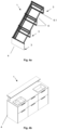
- the framings 3 can be made of conventional structural profiles 6, of which one is shown in Fig. 6 .
- the non-positive and/or positive connection 5 can best be seen from Fig. 2 .
- the first retaining element 5.1 is arranged on the rear side of the decorative panel 4 and the second retaining element 5.2 is arranged on the framing 3 or is made in one piece with the framing 3.
- the first and second retaining elements 5.1, 5.2 are made identical to one another and are designed as profile strips. In this case, they have a C-shape in cross-section (see Fig. 3 ). These profile strips are e.g. glued in a substance-locking manner to the rear side of the decorative panel 4 or even can be formed monolithic with the rear side of the decorative panel 4.
- Both retaining elements 5.1, 5.2 can engage with each other such that the decorative panel 4 can be suspended removably on the framing 3.
- the first and second retaining elements 5.1, 5.2 are separated from each other and the non-positive and/or positive connection 5 is opened.
- the non-positive and/or positive connection 5 is designed such that the decorative panel 4 can be connected to the framing 3 and detached therefrom without using a tool.
- the decorative panels 4 for the side walls of the bathroom cabinet can also be detached from the framing 3.
- Fig. 4a and 4b show a spatial view of a furnishing item 1 being assembled according to another embodiment of the invention.
- the corpus 2 comprises a plurality of framings 3 which are arranged at a distance from one another.
- Each framing 3 can preferably form a side part, a top, a bottom and/or a rear wall of the furnishing item 1.
- All of the framings 3 are made of structural profiles 6. These structural profiles 6 are provided on one or more of their sides with at least one longitudinal groove 6.1 (see Fig. 6 ), into which a complementarily formed slot nut 7 (see Fig. 5a and 5b ) can be introduced.
- individual framings 3 can be detachably joined together by the use of further structural profiles 6 and slot nuts 7.
- Fig. 5a shows a spatial view and Fig. 5b a side view of a respective slot nut 7 which is separated in two part-slot nuts 7.1, 7.2.
- the both part-slots nut 7.1, 7.2 comprise a T-shape or a mushroom shape in cross-section to the longitudinal axis of the structural profile 6 and that shape is complementary to the profile of the longitudinal groove of the structural profile 6.
- the slot nuts 7 may comprises at least one threaded bore and into which a corresponding screw can be introduced in order to releasably clamp the slot nut 7 within the longitudinal groove 6.1 against the boundary surfaces thereof.
- the part-slot nut 7.1 comprises a rotationally symmetrical head 7.1.1, such as a mushroom head, and an adjoining shaft 7.1.2 with a smaller external diameter than that of the head 7.1.1.
- the head 7.1.1 is designed such in relation to the longitudinal groove 6.1 of the structural profile 6, in which it is guided, that it is freely movable with play in the longitudinal groove 6.1 along the longitudinal axis of the structural profile 6.
- the play is chosen such that a tilting in the direction away from the longitudinal axis of the structural profile 6 between the contact surfaces of the part-slot nut 7.1, 7.2 and the boundary surfaces of the longitudinal groove 6.1 is between 0.01 and 0.1 mm.
- the slot nut 7, especially the part-slot nut 7.1, 7.2 can easily be positioned on the desired position along the longitudinal groove 6.1.
- the play against tilting can also be easily adjusted, respectively, by the use of, a spacer sleeve 7.1.4. It surrounds the shaft 7.1.2 and is arranged between the head 7.1.1 of the one part-slot nut 7.1 and the other part-slot nut 7.2.
- the spacer sleeve 7.1.4 can be dimensioned in its length such that the corresponding play of the head 7.1.1 against tilting in relation to the boundary surfaces of the longitudinal groove 6.1 is adjusted accordingly.
- the part-slot nuts 7.1, 7.2 two structural profiles 6 lying directly opposite each other, e.g. the longitudinal grooves 6.1 lying congruently one above the other, can be connected to each other.
- the two part-slot nuts 7.1, 7.2 can be designed such that they are separably connected to each other or are formed in one piece with each other.
- the part-slot nut 7.1 may have a spring-biased ball 7.1.3 at its head 7.1.1, the ball 7.1.3 being arranged on the side of the head facing away from the shaft 7.1.2, so that when the head 7.1.1 is pushed into the longitudinal groove, the ball 7.1.3 runs on the structural profile 6, in detail on one of the (inner) boundary surfaces of the longitudinal groove 6.1 for ease of sliding.
- Fig. 1c there are also provided such part-slot nuts 7.1, 7.2 at each framing 3. With these part-slot nuts 7.1, 7.2, the bathroom cabinet may be easily attached to the wall shown in Fig. 1a and 1b .
- the multiple framings 3, which are in this case parallel to each other, are also formed by a plurality of structural profiles 6 by connecting them with slot nuts 7.
- This construction forms the corpus 2 of the furnishing item, in this case being an outdoor kitchen.
- the outdoor kitchen may have shelves and a sink. At least the both sides of the outdoor kitchen as well as the rear side thereof may be provided with an exchangeable decorative panel 4 as disclosed in the foregoing Figs.
- Fig. 7 and 8 each disclose a spatial view of a detail of an embodiment of an end bar 8 of the modular system.
- Each end bar 8 comprises a base 8.1 and two thighs 8.2 as ledges. With these two thighs 8.2, the end bar 8 can be inserted into the framing 3, such that the two thighs 8.2 can be in contact and thus guided on the framing 3. After insertion the base can be flush and clear of play with the decorative panel 4. Therefore, the base can be at least partly made of the same material as the decorative panel 4 is made or can have such a decorative panel 4 fitted to the base 8.1. Further, the base can have a shoulder 8.3, which is hidden behind the leading edge 8.4 of the decorative panel 4 on which a light source, like a LED stripe can be fixed. Such, an indirect source of light can be included in the furnishing item.
- the furnishing item is a modular system of furniture with high flexibility in arrangement and sustainability.
- structural profiles 6 as internal struts enables the attachment of drawer runners, door hinges and shelf supports. If used in walls, additionally to the decorative effect, the use of a framing 3 also has the advantage of a "ventilated" facade. At the same time, installations can be integrated behind that wall. Shelving boards can also be changed if desired since they are only hooked into the wall without tools.
Landscapes
- Engineering & Computer Science (AREA)
- Architecture (AREA)
- General Engineering & Computer Science (AREA)
- Life Sciences & Earth Sciences (AREA)
- Wood Science & Technology (AREA)
- Civil Engineering (AREA)
- Structural Engineering (AREA)
- Mechanical Engineering (AREA)
- Connection Of Plates (AREA)
- Furniture Connections (AREA)
Claims (11)
- Einrichtungsgegenstand (1), umfassend einen Korpus (2) mit mindestens einem Rahmen (3), der aus einer Vielzahl von Strukturprofilen (6) zu einem Rahmen zusammengesetzt ist, wobei an dem mindestens einen Rahmen (3) ein Dekorpaneel befestigbar und mittels einer kraft- und/oder formschlüssigen Verbindung (5) mit dem Rahmen (3) verbindbar und von diesem lösbar ist, wobei die kraft- und/oder formschlüssige Verbindung (5) ein erstes Rückhalteelement (5.1) und ein zweites, komplementär ausgebildetes Rückhalteelement (5.2) aufweist, wobei das erste Rückhalteelement (5.1) substanzschlüssig mit der Rückseite des Dekorpaneels (4) verbunden ist oder von diesem gebildet wird und das zweite Rückhalteelement (5.2) kraft- und/oder formschlüssig am Rahmen (3) angebracht ist oder von diesem gebildet wird, wobei die Strukturprofile (6) an einer oder mehrerer ihrer Seiten mit mindestens einer Längsnut (6.1) versehen sind, in die ein komplementär ausgebildeter Nutenstein (7) einbringbar ist, wobei vorzugsweise der Nutenstein (7) mindestens eine Gewindebohrung umfasst und in die eine entsprechende Schraube einbringbar ist, um den Nutenstein (7) innerhalb der Längsnut (6.1) gegen deren Begrenzungsflächen lösbar zu klemmen, wobei zum Verbinden zweier sich unmittelbar gegenüberliegender Strukturprofile (6) entsprechend zwei Teilnutensteine (7.1, 7.2) bereitgestellt sind, die lösbar miteinander verbunden oder einstückig miteinander ausgebildet sind, wobei einer der Teilnutensteine (7.1) einen vorzugsweise rotationssymmetrischen Kopf (7.1.1), wie einen Pilzkopf, und einen anschließenden Schaft (7.1.2) mit kleinerem Außendurchmesser als dem des Kopfes (7.1.1) umfasst, und der Kopf vorzugsweise in Bezug auf die Längsnut (6.1), in der er geführt ist, so ausgebildet ist, dass er mit Spiel in der Längsnut (6.1) entlang der Längsachse des Strukturprofils (6) frei beweglich ist, wobei das Spiel gegen Verkippen in Richtung weg von der Längsachse des Strukturprofils (6) zwischen den Kontaktflächen des einen Teilnutensteins (7.1) und den Begrenzungsflächen der Längsnut (6.1) zwischen 0,01 und 0,1 mm beträgt, um ein Verklemmen des einteiligen Nutensteins (7.1) beim Verschieben entlang der Längsachse des Strukturprofils (6) zu verhindern, dadurch gekennzeichnet, dass der eine Teilnutenstein (7.1) an seinem Kopf eine federbelastete Kugel (7.1.3) aufweist, wobei die Kugel (7.1.3) auf der von dem Schaft (7.1.2) abgewandten Seite des Kopfes (7.1.1) angeordnet ist, sodass, wenn der Kopf (7.1.1) in die Längsnut (6.1) eingeschoben wird, die Kugel (7.1.3) auf einer der Begrenzungsflächen der Längsnut (6.1) gleitet, und vorzugsweise dadurch, dass zum Einstellen des Spiels gegen Verkippen eine Distanzhülse (7.1.4) bereitgestellt wird, die den Schaft (7.1.2) umgibt und zwischen dem Kopf (7.1.1) des einen Teilnutensteins (7.1) und dem anderen Teilnutenstein (7.2) angeordnet und in ihrer Länge so bemessen ist, dass das entsprechende Spiel des Kopfes (7.1.1) gegen Verkippen in Bezug auf die Begrenzungsflächen der Längsnut (6.1) entsprechend eingestellt wird.
- Einrichtungsgegenstand (1) nach Anspruch 1, dadurch gekennzeichnet, dass die materialschlüssige Verbindung des ersten Rückhalteelements (5.1) mit dem Dekorpaneel eine Klebeverbindung ist, wobei die Klebeverbindung vorzugsweise nach DIN 2304 ausgeführt ist, wobei der Kleber der Klebeverbindung vorzugsweise ein Zweikomponentenkleber, bevorzugt ein Zweikomponentenkleber auf Basis von Polyurethan ist, wobei vorzugsweise das Polyurethan Methylendiphenyl-Diisocyanat (MDI) oder Hexamethylen-Diisocyanat (HDI) als Isocyanat umfasst, wobei das Polyol vorzugsweise ein Aminopolyol ist.
- Einrichtungsgegenstand (1) nach Anspruch 1 oder 2, dadurch gekennzeichnet, dass die Biegefestigkeit der verklebten Teile, gemessen nach DIN EN 12372, mindestens 0,5 N/mm2 und vorzugsweise mindestens 2 N/mm2 beträgt; und/oder
die Scherfestigkeit 1 bis 15 N/mm2, vorzugsweise 1,5 bis 10 N/mm2und besonders bevorzugt 1,5 bis 5 N/mm2 beträgt; und/oder die tolerierte Belichtungsdauer bei künstlicher Bewitterung mit fluoreszierenden UV-Lampen und Wasser, gemessen nach DIN EN 927-6, mindestens 500 Stunden, vorzugsweise mindestens 750 Stunden beträgt. - Einrichtungsgegenstand (1) nach einem der Ansprüche 1, dadurch gekennzeichnet, dass die Längsnut (6.1) des Strukturprofils im Querschnitt senkrecht zur Längsachse des Strukturprofils (6) gesehen eine T-Form oder eine Pilzform aufweist.
- Einrichtungsgegenstand (1) nach einem der vorhergehenden Ansprüche, dadurch gekennzeichnet, dass der Korpus (2) eine Vielzahl von Rahmen (3) umfasst, die in einem Abstand zueinander angeordnet ist, wobei jeder Rahmen (3) dann vorzugsweise ein Seitenteil, eine Oberseite, einen Boden und/oder eine Rückwand des Einrichtungsgegenstandes (1) bildet und die Rahmen (3) mittels Strukturprofilen (6) und Nutensteinen (7) miteinander verbindbar sind.
- Einrichtungsgegenstand (1) nach einem der vorhergehenden Ansprüche, dadurch gekennzeichnet, dass das erste und zweite Rückhalteelement (5.1, 5.2) miteinander identisch sind und als Profilleisten ausgebildet sind, die im Querschnitt eine C-, eine L- oder eine Z-Form aufweisen.
- Einrichtungsgegenstand (1) nach Anspruch 6, dadurch gekennzeichnet, dass die Breite des Profilstreifens zwischen 2 und 4 cm beträgt.
- Einrichtungsgegenstand (1) nach einem der vorhergehenden Ansprüche, dadurch gekennzeichnet, dass das Dekorpaneel (4) mindestens teilweise aus einem Stein, wie Naturstein, Schamottstein oder Quarzkompositstein, aus Keramik, wie Tonkeramik oder Glaskeramik, aus Glas, wie Spiegelglas oder gehärtetem Glas, aus einem Metall, wie Aluminium, Messing oder Edelstahl, aus einem Kunststoff, wie Acryl, aus Holz, aus einem Hochdrucklaminat (HPL), aus einer beschichteten MDF- oder Spanplatte, aus einem Verbundmaterial aus Aluminium und Kunststoff oder aus Kombinationen der vorgenannten Materialien besteht.
- Einrichtungsgegenstand (1) nach Anspruch 8, dadurch gekennzeichnet, dass das Dekorpaneel (4) eine Dicke von 3 bis 20 mm, vorzugsweise 4 bis 12 mm, aufweist.
- Verwendung eines Einrichtungsgegenstandes (1) nach einem der Ansprüche 1 bis 9 als Wandverkleidung oder Möbel für den Innenbereich, wie Schrank, Regal, insbesondere für Wohnräume wie Wohnzimmer, Küchen oder Bäder oder Geschäftsräume wie Büros.
- Verwendung eines Einrichtungsgegenstandes (1) nach einem der Ansprüche 1 bis 9 als Stauraum zur Unterbringung von Fahrzeugen, Geräten, Waren und Materialien oder als Möbel für den Außenbereich, wie eine Außenküche.
Priority Applications (2)
| Application Number | Priority Date | Filing Date | Title |
|---|---|---|---|
| EP21185908.7A EP4119003B1 (de) | 2021-07-15 | 2021-07-15 | Einrichtungsgegenstand und dessen verwendung |
| EP22184659.5A EP4119004A1 (de) | 2021-07-15 | 2022-07-13 | Einrichtungsgegenstand und dessen verwendung |
Applications Claiming Priority (1)
| Application Number | Priority Date | Filing Date | Title |
|---|---|---|---|
| EP21185908.7A EP4119003B1 (de) | 2021-07-15 | 2021-07-15 | Einrichtungsgegenstand und dessen verwendung |
Publications (3)
| Publication Number | Publication Date |
|---|---|
| EP4119003A1 EP4119003A1 (de) | 2023-01-18 |
| EP4119003B1 true EP4119003B1 (de) | 2024-09-11 |
| EP4119003C0 EP4119003C0 (de) | 2024-09-11 |
Family
ID=76942933
Family Applications (2)
| Application Number | Title | Priority Date | Filing Date |
|---|---|---|---|
| EP21185908.7A Active EP4119003B1 (de) | 2021-07-15 | 2021-07-15 | Einrichtungsgegenstand und dessen verwendung |
| EP22184659.5A Withdrawn EP4119004A1 (de) | 2021-07-15 | 2022-07-13 | Einrichtungsgegenstand und dessen verwendung |
Family Applications After (1)
| Application Number | Title | Priority Date | Filing Date |
|---|---|---|---|
| EP22184659.5A Withdrawn EP4119004A1 (de) | 2021-07-15 | 2022-07-13 | Einrichtungsgegenstand und dessen verwendung |
Country Status (1)
| Country | Link |
|---|---|
| EP (2) | EP4119003B1 (de) |
Family Cites Families (7)
| Publication number | Priority date | Publication date | Assignee | Title |
|---|---|---|---|---|
| FR1480683A (fr) * | 1966-05-20 | 1967-05-12 | Elément de construction de meubles et pièce d'assemblage correspondante | |
| US4021129A (en) * | 1976-01-12 | 1977-05-03 | Nexus Manufacturing Limited | Mechanical connections between adjacent members |
| AUPO215996A0 (en) * | 1996-09-05 | 1996-10-03 | James Hardie International Finance B.V. | An improved cladding board mounting system |
| KR101115327B1 (ko) * | 2011-05-04 | 2012-03-09 | 정재은 | 프로파일 커버용 고정구의 구조 |
| WO2013125821A1 (ko) * | 2012-02-23 | 2013-08-29 | Lee Jung-Yeop | 조립식 건축물용 육면체 단위 유닛 및 상기 육면체 단위 유닛의 조립방법 |
| GB2505011A (en) * | 2012-08-15 | 2014-02-19 | Alberto Dipierro | Device for mounting items on walls |
| KR101267731B1 (ko) * | 2012-12-04 | 2013-05-27 | 폴성 킴 | 상품 진열용 벽면 조립체 |
-
2021
- 2021-07-15 EP EP21185908.7A patent/EP4119003B1/de active Active
-
2022
- 2022-07-13 EP EP22184659.5A patent/EP4119004A1/de not_active Withdrawn
Also Published As
| Publication number | Publication date |
|---|---|
| EP4119004A1 (de) | 2023-01-18 |
| EP4119003C0 (de) | 2024-09-11 |
| EP4119003A1 (de) | 2023-01-18 |
Similar Documents
| Publication | Publication Date | Title |
|---|---|---|
| US5405017A (en) | Modular casket display system | |
| US5125726A (en) | Device for the presentation of objects | |
| CA2332691C (en) | Death care merchandising system | |
| US4381876A (en) | Front lighted display case | |
| US9930959B2 (en) | Modular furniture and structures | |
| WO2009015311A1 (en) | Modular furniture system | |
| NZ583856A (en) | Surface coverings including decorative strips with supports received in notched back surface | |
| US8087735B1 (en) | Free standing furniture kit and method of assembly | |
| US20250057315A1 (en) | Wall mounting apparatus | |
| US20020043349A1 (en) | Decorative screen with removable panel inserts | |
| US7784626B2 (en) | Wall hanging system | |
| EP4119003B1 (de) | Einrichtungsgegenstand und dessen verwendung | |
| US9119469B2 (en) | Platform assembly for supporting cabinets | |
| US20080067906A1 (en) | Modular components for building structures | |
| JP2792832B2 (ja) | 持出し棚取付け用壁の構築方法並びに持出し棚取付け用壁および該壁を形成するパネル | |
| JPS5921406B2 (ja) | 組立式什器付間仕切り | |
| JP7591207B2 (ja) | 分割型引戸収納ユニット家具 | |
| US20260071436A1 (en) | Wall panel system | |
| US20240251947A1 (en) | Wall panel furniture system | |
| JP3105699U (ja) | 組立式自立型家具 | |
| CA2510204C (en) | Wall hanging system | |
| EP2146601B1 (de) | Möbelsystem | |
| JP2006161316A (ja) | 物品取付け用スライド材及びそれを使用した物品取付け構造 | |
| KR20230168911A (ko) | 석재 거실장 | |
| EP3691492A1 (de) | Schrank mit mehrteiliger rückwand |
Legal Events
| Date | Code | Title | Description |
|---|---|---|---|
| PUAI | Public reference made under article 153(3) epc to a published international application that has entered the european phase |
Free format text: ORIGINAL CODE: 0009012 |
|
| STAA | Information on the status of an ep patent application or granted ep patent |
Free format text: STATUS: THE APPLICATION HAS BEEN PUBLISHED |
|
| AK | Designated contracting states |
Kind code of ref document: A1 Designated state(s): AL AT BE BG CH CY CZ DE DK EE ES FI FR GB GR HR HU IE IS IT LI LT LU LV MC MK MT NL NO PL PT RO RS SE SI SK SM TR |
|
| STAA | Information on the status of an ep patent application or granted ep patent |
Free format text: STATUS: REQUEST FOR EXAMINATION WAS MADE |
|
| 17P | Request for examination filed |
Effective date: 20230714 |
|
| RBV | Designated contracting states (corrected) |
Designated state(s): AL AT BE BG CH CY CZ DE DK EE ES FI FR GB GR HR HU IE IS IT LI LT LU LV MC MK MT NL NO PL PT RO RS SE SI SK SM TR |
|
| GRAP | Despatch of communication of intention to grant a patent |
Free format text: ORIGINAL CODE: EPIDOSNIGR1 |
|
| STAA | Information on the status of an ep patent application or granted ep patent |
Free format text: STATUS: GRANT OF PATENT IS INTENDED |
|
| INTG | Intention to grant announced |
Effective date: 20240410 |
|
| GRAS | Grant fee paid |
Free format text: ORIGINAL CODE: EPIDOSNIGR3 |
|
| GRAA | (expected) grant |
Free format text: ORIGINAL CODE: 0009210 |
|
| STAA | Information on the status of an ep patent application or granted ep patent |
Free format text: STATUS: THE PATENT HAS BEEN GRANTED |
|
| AK | Designated contracting states |
Kind code of ref document: B1 Designated state(s): AL AT BE BG CH CY CZ DE DK EE ES FI FR GB GR HR HU IE IS IT LI LT LU LV MC MK MT NL NO PL PT RO RS SE SI SK SM TR |
|
| REG | Reference to a national code |
Ref country code: GB Ref legal event code: FG4D |
|
| REG | Reference to a national code |
Ref country code: CH Ref legal event code: EP |
|
| REG | Reference to a national code |
Ref country code: DE Ref legal event code: R096 Ref document number: 602021018558 Country of ref document: DE |
|
| REG | Reference to a national code |
Ref country code: IE Ref legal event code: FG4D |
|
| U01 | Request for unitary effect filed |
Effective date: 20240920 |
|
| U07 | Unitary effect registered |
Designated state(s): AT BE BG DE DK EE FI FR IT LT LU LV MT NL PT RO SE SI Effective date: 20241018 |
|
| PG25 | Lapsed in a contracting state [announced via postgrant information from national office to epo] |
Ref country code: NO Free format text: LAPSE BECAUSE OF FAILURE TO SUBMIT A TRANSLATION OF THE DESCRIPTION OR TO PAY THE FEE WITHIN THE PRESCRIBED TIME-LIMIT Effective date: 20241211 |
|
| PG25 | Lapsed in a contracting state [announced via postgrant information from national office to epo] |
Ref country code: GR Free format text: LAPSE BECAUSE OF FAILURE TO SUBMIT A TRANSLATION OF THE DESCRIPTION OR TO PAY THE FEE WITHIN THE PRESCRIBED TIME-LIMIT Effective date: 20241212 |
|
| PG25 | Lapsed in a contracting state [announced via postgrant information from national office to epo] |
Ref country code: HR Free format text: LAPSE BECAUSE OF FAILURE TO SUBMIT A TRANSLATION OF THE DESCRIPTION OR TO PAY THE FEE WITHIN THE PRESCRIBED TIME-LIMIT Effective date: 20240911 |
|
| PG25 | Lapsed in a contracting state [announced via postgrant information from national office to epo] |
Ref country code: ES Free format text: LAPSE BECAUSE OF FAILURE TO SUBMIT A TRANSLATION OF THE DESCRIPTION OR TO PAY THE FEE WITHIN THE PRESCRIBED TIME-LIMIT Effective date: 20240911 Ref country code: RS Free format text: LAPSE BECAUSE OF FAILURE TO SUBMIT A TRANSLATION OF THE DESCRIPTION OR TO PAY THE FEE WITHIN THE PRESCRIBED TIME-LIMIT Effective date: 20241211 |
|
| PG25 | Lapsed in a contracting state [announced via postgrant information from national office to epo] |
Ref country code: RS Free format text: LAPSE BECAUSE OF FAILURE TO SUBMIT A TRANSLATION OF THE DESCRIPTION OR TO PAY THE FEE WITHIN THE PRESCRIBED TIME-LIMIT Effective date: 20241211 Ref country code: NO Free format text: LAPSE BECAUSE OF FAILURE TO SUBMIT A TRANSLATION OF THE DESCRIPTION OR TO PAY THE FEE WITHIN THE PRESCRIBED TIME-LIMIT Effective date: 20241211 Ref country code: HR Free format text: LAPSE BECAUSE OF FAILURE TO SUBMIT A TRANSLATION OF THE DESCRIPTION OR TO PAY THE FEE WITHIN THE PRESCRIBED TIME-LIMIT Effective date: 20240911 Ref country code: GR Free format text: LAPSE BECAUSE OF FAILURE TO SUBMIT A TRANSLATION OF THE DESCRIPTION OR TO PAY THE FEE WITHIN THE PRESCRIBED TIME-LIMIT Effective date: 20241212 Ref country code: ES Free format text: LAPSE BECAUSE OF FAILURE TO SUBMIT A TRANSLATION OF THE DESCRIPTION OR TO PAY THE FEE WITHIN THE PRESCRIBED TIME-LIMIT Effective date: 20240911 |
|
| PG25 | Lapsed in a contracting state [announced via postgrant information from national office to epo] |
Ref country code: IS Free format text: LAPSE BECAUSE OF FAILURE TO SUBMIT A TRANSLATION OF THE DESCRIPTION OR TO PAY THE FEE WITHIN THE PRESCRIBED TIME-LIMIT Effective date: 20250111 |
|
| PG25 | Lapsed in a contracting state [announced via postgrant information from national office to epo] |
Ref country code: SM Free format text: LAPSE BECAUSE OF FAILURE TO SUBMIT A TRANSLATION OF THE DESCRIPTION OR TO PAY THE FEE WITHIN THE PRESCRIBED TIME-LIMIT Effective date: 20240911 |
|
| PG25 | Lapsed in a contracting state [announced via postgrant information from national office to epo] |
Ref country code: CZ Free format text: LAPSE BECAUSE OF FAILURE TO SUBMIT A TRANSLATION OF THE DESCRIPTION OR TO PAY THE FEE WITHIN THE PRESCRIBED TIME-LIMIT Effective date: 20240911 Ref country code: PL Free format text: LAPSE BECAUSE OF FAILURE TO SUBMIT A TRANSLATION OF THE DESCRIPTION OR TO PAY THE FEE WITHIN THE PRESCRIBED TIME-LIMIT Effective date: 20240911 |
|
| PG25 | Lapsed in a contracting state [announced via postgrant information from national office to epo] |
Ref country code: SK Free format text: LAPSE BECAUSE OF FAILURE TO SUBMIT A TRANSLATION OF THE DESCRIPTION OR TO PAY THE FEE WITHIN THE PRESCRIBED TIME-LIMIT Effective date: 20240911 |
|
| PLBE | No opposition filed within time limit |
Free format text: ORIGINAL CODE: 0009261 |
|
| STAA | Information on the status of an ep patent application or granted ep patent |
Free format text: STATUS: NO OPPOSITION FILED WITHIN TIME LIMIT |
|
| 26N | No opposition filed |
Effective date: 20250612 |
|
| U20 | Renewal fee for the european patent with unitary effect paid |
Year of fee payment: 5 Effective date: 20250728 |
|
| PGFP | Annual fee paid to national office [announced via postgrant information from national office to epo] |
Ref country code: CH Payment date: 20250801 Year of fee payment: 5 |
|
| GBPC | Gb: european patent ceased through non-payment of renewal fee |
Effective date: 20250715 |