EP4117058A1 - All solid-state battery and manufacturing method for all solid-state battery - Google Patents
All solid-state battery and manufacturing method for all solid-state battery Download PDFInfo
- Publication number
- EP4117058A1 EP4117058A1 EP22183041.7A EP22183041A EP4117058A1 EP 4117058 A1 EP4117058 A1 EP 4117058A1 EP 22183041 A EP22183041 A EP 22183041A EP 4117058 A1 EP4117058 A1 EP 4117058A1
- Authority
- EP
- European Patent Office
- Prior art keywords
- layer
- solid electrolyte
- electrolyte layer
- solid
- active material
- Prior art date
- Legal status (The legal status is an assumption and is not a legal conclusion. Google has not performed a legal analysis and makes no representation as to the accuracy of the status listed.)
- Pending
Links
- 238000004519 manufacturing process Methods 0.000 title claims description 29
- 239000007784 solid electrolyte Substances 0.000 claims abstract description 314
- 239000007774 positive electrode material Substances 0.000 claims description 57
- 239000000463 material Substances 0.000 claims description 50
- 239000007773 negative electrode material Substances 0.000 claims description 49
- 238000012546 transfer Methods 0.000 claims description 47
- WHXSMMKQMYFTQS-UHFFFAOYSA-N Lithium Chemical compound [Li] WHXSMMKQMYFTQS-UHFFFAOYSA-N 0.000 claims description 36
- 229910052744 lithium Inorganic materials 0.000 claims description 36
- 238000010030 laminating Methods 0.000 claims description 28
- 238000000576 coating method Methods 0.000 claims description 20
- 239000000758 substrate Substances 0.000 claims description 18
- 239000011248 coating agent Substances 0.000 claims description 16
- NINIDFKCEFEMDL-UHFFFAOYSA-N Sulfur Chemical compound [S] NINIDFKCEFEMDL-UHFFFAOYSA-N 0.000 claims description 11
- 229910052717 sulfur Inorganic materials 0.000 claims description 11
- 239000011593 sulfur Substances 0.000 claims description 11
- 239000010410 layer Substances 0.000 description 517
- 239000011230 binding agent Substances 0.000 description 39
- 239000011149 active material Substances 0.000 description 23
- 239000011888 foil Substances 0.000 description 23
- 238000000034 method Methods 0.000 description 20
- 230000000052 comparative effect Effects 0.000 description 19
- 229910052751 metal Inorganic materials 0.000 description 17
- 239000002184 metal Substances 0.000 description 17
- 239000002245 particle Substances 0.000 description 17
- 239000002002 slurry Substances 0.000 description 11
- 239000000203 mixture Substances 0.000 description 10
- 239000005062 Polybutadiene Substances 0.000 description 9
- 229920002857 polybutadiene Polymers 0.000 description 9
- IMNFDUFMRHMDMM-UHFFFAOYSA-N N-Heptane Chemical compound CCCCCCC IMNFDUFMRHMDMM-UHFFFAOYSA-N 0.000 description 8
- 238000003825 pressing Methods 0.000 description 8
- PXHVJJICTQNCMI-UHFFFAOYSA-N Nickel Chemical compound [Ni] PXHVJJICTQNCMI-UHFFFAOYSA-N 0.000 description 7
- 238000004806 packaging method and process Methods 0.000 description 7
- 229920005989 resin Polymers 0.000 description 7
- 239000011347 resin Substances 0.000 description 7
- 230000003746 surface roughness Effects 0.000 description 7
- OKTJSMMVPCPJKN-UHFFFAOYSA-N Carbon Chemical compound [C] OKTJSMMVPCPJKN-UHFFFAOYSA-N 0.000 description 6
- 239000002033 PVDF binder Substances 0.000 description 6
- MCMNRKCIXSYSNV-UHFFFAOYSA-N Zirconium dioxide Chemical compound O=[Zr]=O MCMNRKCIXSYSNV-UHFFFAOYSA-N 0.000 description 6
- 238000007599 discharging Methods 0.000 description 6
- 230000000694 effects Effects 0.000 description 6
- -1 polytetrafluoroethylene Polymers 0.000 description 6
- 229920001343 polytetrafluoroethylene Polymers 0.000 description 6
- 239000004810 polytetrafluoroethylene Substances 0.000 description 6
- 229920002981 polyvinylidene fluoride Polymers 0.000 description 6
- 230000000452 restraining effect Effects 0.000 description 6
- 239000002203 sulfidic glass Substances 0.000 description 6
- 230000008602 contraction Effects 0.000 description 5
- 229910003480 inorganic solid Inorganic materials 0.000 description 5
- 229910004600 P2S5 Inorganic materials 0.000 description 4
- XUPYJHCZDLZNFP-UHFFFAOYSA-N butyl butanoate Chemical compound CCCCOC(=O)CCC XUPYJHCZDLZNFP-UHFFFAOYSA-N 0.000 description 4
- 229910052799 carbon Inorganic materials 0.000 description 4
- 238000001035 drying Methods 0.000 description 4
- 238000011156 evaluation Methods 0.000 description 4
- 229910052759 nickel Inorganic materials 0.000 description 4
- 239000011164 primary particle Substances 0.000 description 4
- 229910001220 stainless steel Inorganic materials 0.000 description 4
- 239000010935 stainless steel Substances 0.000 description 4
- 229920003048 styrene butadiene rubber Polymers 0.000 description 4
- 229910009297 Li2S-P2S5 Inorganic materials 0.000 description 3
- 229910009228 Li2S—P2S5 Inorganic materials 0.000 description 3
- 239000004743 Polypropylene Substances 0.000 description 3
- 229910052782 aluminium Inorganic materials 0.000 description 3
- YFRNYWVKHCQRPE-UHFFFAOYSA-N buta-1,3-diene;prop-2-enoic acid Chemical compound C=CC=C.OC(=O)C=C YFRNYWVKHCQRPE-UHFFFAOYSA-N 0.000 description 3
- 229910052802 copper Inorganic materials 0.000 description 3
- 239000010949 copper Substances 0.000 description 3
- 210000001787 dendrite Anatomy 0.000 description 3
- 229920001971 elastomer Polymers 0.000 description 3
- 239000005001 laminate film Substances 0.000 description 3
- 238000005259 measurement Methods 0.000 description 3
- 238000000691 measurement method Methods 0.000 description 3
- 238000003701 mechanical milling Methods 0.000 description 3
- 238000002156 mixing Methods 0.000 description 3
- 238000000465 moulding Methods 0.000 description 3
- 229920000620 organic polymer Polymers 0.000 description 3
- 239000005518 polymer electrolyte Substances 0.000 description 3
- 229920001155 polypropylene Polymers 0.000 description 3
- 239000005060 rubber Substances 0.000 description 3
- 239000007858 starting material Substances 0.000 description 3
- 125000000383 tetramethylene group Chemical group [H]C([H])([*:1])C([H])([H])C([H])([H])C([H])([H])[*:2] 0.000 description 3
- 229910000733 Li alloy Inorganic materials 0.000 description 2
- HBBGRARXTFLTSG-UHFFFAOYSA-N Lithium ion Chemical compound [Li+] HBBGRARXTFLTSG-UHFFFAOYSA-N 0.000 description 2
- 229910006309 Li—Mg Inorganic materials 0.000 description 2
- RTAQQCXQSZGOHL-UHFFFAOYSA-N Titanium Chemical compound [Ti] RTAQQCXQSZGOHL-UHFFFAOYSA-N 0.000 description 2
- JDZCKJOXGCMJGS-UHFFFAOYSA-N [Li].[S] Chemical compound [Li].[S] JDZCKJOXGCMJGS-UHFFFAOYSA-N 0.000 description 2
- 238000013459 approach Methods 0.000 description 2
- 210000004027 cell Anatomy 0.000 description 2
- 229910052804 chromium Inorganic materials 0.000 description 2
- 239000011247 coating layer Substances 0.000 description 2
- 238000007723 die pressing method Methods 0.000 description 2
- 239000003792 electrolyte Substances 0.000 description 2
- 230000001747 exhibiting effect Effects 0.000 description 2
- 239000011521 glass Substances 0.000 description 2
- 229910052737 gold Inorganic materials 0.000 description 2
- 229910052742 iron Inorganic materials 0.000 description 2
- 239000001989 lithium alloy Substances 0.000 description 2
- 229910001416 lithium ion Inorganic materials 0.000 description 2
- AUHZEENZYGFFBQ-UHFFFAOYSA-N mesitylene Substances CC1=CC(C)=CC(C)=C1 AUHZEENZYGFFBQ-UHFFFAOYSA-N 0.000 description 2
- 125000001827 mesitylenyl group Chemical group [H]C1=C(C(*)=C(C([H])=C1C([H])([H])[H])C([H])([H])[H])C([H])([H])[H] 0.000 description 2
- 229910052697 platinum Inorganic materials 0.000 description 2
- 230000002829 reductive effect Effects 0.000 description 2
- 238000007789 sealing Methods 0.000 description 2
- 239000011163 secondary particle Substances 0.000 description 2
- 229910052709 silver Inorganic materials 0.000 description 2
- 229910052719 titanium Inorganic materials 0.000 description 2
- 238000003826 uniaxial pressing Methods 0.000 description 2
- 229910052725 zinc Inorganic materials 0.000 description 2
- 229910006194 Li1+xAlxGe2-x(PO4)3 Inorganic materials 0.000 description 1
- 229910006196 Li1+xAlxGe2−x(PO4)3 Inorganic materials 0.000 description 1
- 229910001216 Li2S Inorganic materials 0.000 description 1
- 229910009311 Li2S-SiS2 Inorganic materials 0.000 description 1
- 229910009176 Li2S—P2 Inorganic materials 0.000 description 1
- 229910009225 Li2S—P2S5—GeS2 Inorganic materials 0.000 description 1
- 229910009433 Li2S—SiS2 Inorganic materials 0.000 description 1
- 229910010835 LiI-Li2S-P2S5 Inorganic materials 0.000 description 1
- 229910010833 LiI-Li2S-SiS2 Inorganic materials 0.000 description 1
- 229910010842 LiI—Li2S—P2O5 Inorganic materials 0.000 description 1
- 229910010840 LiI—Li2S—P2S5 Inorganic materials 0.000 description 1
- 229910010855 LiI—Li2S—SiS2 Inorganic materials 0.000 description 1
- 229910010847 LiI—Li3PO4-P2S5 Inorganic materials 0.000 description 1
- 229910010864 LiI—Li3PO4—P2S5 Inorganic materials 0.000 description 1
- 229910012305 LiPON Inorganic materials 0.000 description 1
- 229910001228 Li[Ni1/3Co1/3Mn1/3]O2 (NCM 111) Inorganic materials 0.000 description 1
- 229910000676 Si alloy Inorganic materials 0.000 description 1
- VYPSYNLAJGMNEJ-UHFFFAOYSA-N Silicium dioxide Chemical compound O=[Si]=O VYPSYNLAJGMNEJ-UHFFFAOYSA-N 0.000 description 1
- 239000002174 Styrene-butadiene Substances 0.000 description 1
- RJEIKIOYHOOKDL-UHFFFAOYSA-N [Li].[La] Chemical compound [Li].[La] RJEIKIOYHOOKDL-UHFFFAOYSA-N 0.000 description 1
- 239000006230 acetylene black Substances 0.000 description 1
- 229910045601 alloy Inorganic materials 0.000 description 1
- 239000000956 alloy Substances 0.000 description 1
- 238000005275 alloying Methods 0.000 description 1
- XAGFODPZIPBFFR-UHFFFAOYSA-N aluminium Chemical compound [Al] XAGFODPZIPBFFR-UHFFFAOYSA-N 0.000 description 1
- 239000002134 carbon nanofiber Substances 0.000 description 1
- 239000002388 carbon-based active material Substances 0.000 description 1
- 239000003575 carbonaceous material Substances 0.000 description 1
- 238000006243 chemical reaction Methods 0.000 description 1
- 239000002131 composite material Substances 0.000 description 1
- 238000011109 contamination Methods 0.000 description 1
- 230000007423 decrease Effects 0.000 description 1
- 238000009826 distribution Methods 0.000 description 1
- 239000010439 graphite Substances 0.000 description 1
- 229910002804 graphite Inorganic materials 0.000 description 1
- 229910021385 hard carbon Inorganic materials 0.000 description 1
- 238000010191 image analysis Methods 0.000 description 1
- 230000002401 inhibitory effect Effects 0.000 description 1
- 150000002500 ions Chemical class 0.000 description 1
- 239000003273 ketjen black Substances 0.000 description 1
- 238000007561 laser diffraction method Methods 0.000 description 1
- AMXOYNBUYSYVKV-UHFFFAOYSA-M lithium bromide Inorganic materials [Li+].[Br-] AMXOYNBUYSYVKV-UHFFFAOYSA-M 0.000 description 1
- 229910000625 lithium cobalt oxide Inorganic materials 0.000 description 1
- 150000002642 lithium compounds Chemical class 0.000 description 1
- 229910002102 lithium manganese oxide Inorganic materials 0.000 description 1
- GQYHUHYESMUTHG-UHFFFAOYSA-N lithium niobate Chemical compound [Li+].[O-][Nb](=O)=O GQYHUHYESMUTHG-UHFFFAOYSA-N 0.000 description 1
- 229910001386 lithium phosphate Inorganic materials 0.000 description 1
- BFZPBUKRYWOWDV-UHFFFAOYSA-N lithium;oxido(oxo)cobalt Chemical compound [Li+].[O-][Co]=O BFZPBUKRYWOWDV-UHFFFAOYSA-N 0.000 description 1
- VLXXBCXTUVRROQ-UHFFFAOYSA-N lithium;oxido-oxo-(oxomanganiooxy)manganese Chemical compound [Li+].[O-][Mn](=O)O[Mn]=O VLXXBCXTUVRROQ-UHFFFAOYSA-N 0.000 description 1
- URIIGZKXFBNRAU-UHFFFAOYSA-N lithium;oxonickel Chemical compound [Li].[Ni]=O URIIGZKXFBNRAU-UHFFFAOYSA-N 0.000 description 1
- 239000007769 metal material Substances 0.000 description 1
- 239000004570 mortar (masonry) Substances 0.000 description 1
- 230000003647 oxidation Effects 0.000 description 1
- 238000007254 oxidation reaction Methods 0.000 description 1
- 239000000843 powder Substances 0.000 description 1
- 230000002441 reversible effect Effects 0.000 description 1
- 238000000790 scattering method Methods 0.000 description 1
- 229910052710 silicon Inorganic materials 0.000 description 1
- LIVNPJMFVYWSIS-UHFFFAOYSA-N silicon monoxide Chemical class [Si-]#[O+] LIVNPJMFVYWSIS-UHFFFAOYSA-N 0.000 description 1
- 229910052814 silicon oxide Inorganic materials 0.000 description 1
- 239000002409 silicon-based active material Substances 0.000 description 1
- 239000007787 solid Substances 0.000 description 1
- 229910052596 spinel Inorganic materials 0.000 description 1
- 239000011029 spinel Substances 0.000 description 1
- 150000003464 sulfur compounds Chemical class 0.000 description 1
- 230000001629 suppression Effects 0.000 description 1
- 229920005992 thermoplastic resin Polymers 0.000 description 1
- 229920001187 thermosetting polymer Polymers 0.000 description 1
- TWQULNDIKKJZPH-UHFFFAOYSA-K trilithium;phosphate Chemical compound [Li+].[Li+].[Li+].[O-]P([O-])([O-])=O TWQULNDIKKJZPH-UHFFFAOYSA-K 0.000 description 1
Images


Classifications
-
- H—ELECTRICITY
- H01—ELECTRIC ELEMENTS
- H01M—PROCESSES OR MEANS, e.g. BATTERIES, FOR THE DIRECT CONVERSION OF CHEMICAL ENERGY INTO ELECTRICAL ENERGY
- H01M4/00—Electrodes
- H01M4/02—Electrodes composed of, or comprising, active material
- H01M4/36—Selection of substances as active materials, active masses, active liquids
- H01M4/38—Selection of substances as active materials, active masses, active liquids of elements or alloys
-
- H—ELECTRICITY
- H01—ELECTRIC ELEMENTS
- H01M—PROCESSES OR MEANS, e.g. BATTERIES, FOR THE DIRECT CONVERSION OF CHEMICAL ENERGY INTO ELECTRICAL ENERGY
- H01M10/00—Secondary cells; Manufacture thereof
- H01M10/05—Accumulators with non-aqueous electrolyte
- H01M10/056—Accumulators with non-aqueous electrolyte characterised by the materials used as electrolytes, e.g. mixed inorganic/organic electrolytes
-
- H—ELECTRICITY
- H01—ELECTRIC ELEMENTS
- H01M—PROCESSES OR MEANS, e.g. BATTERIES, FOR THE DIRECT CONVERSION OF CHEMICAL ENERGY INTO ELECTRICAL ENERGY
- H01M10/00—Secondary cells; Manufacture thereof
- H01M10/05—Accumulators with non-aqueous electrolyte
- H01M10/056—Accumulators with non-aqueous electrolyte characterised by the materials used as electrolytes, e.g. mixed inorganic/organic electrolytes
- H01M10/0561—Accumulators with non-aqueous electrolyte characterised by the materials used as electrolytes, e.g. mixed inorganic/organic electrolytes the electrolyte being constituted of inorganic materials only
- H01M10/0562—Solid materials
-
- H—ELECTRICITY
- H01—ELECTRIC ELEMENTS
- H01M—PROCESSES OR MEANS, e.g. BATTERIES, FOR THE DIRECT CONVERSION OF CHEMICAL ENERGY INTO ELECTRICAL ENERGY
- H01M10/00—Secondary cells; Manufacture thereof
- H01M10/04—Construction or manufacture in general
- H01M10/0413—Large-sized flat cells or batteries for motive or stationary systems with plate-like electrodes
-
- H—ELECTRICITY
- H01—ELECTRIC ELEMENTS
- H01M—PROCESSES OR MEANS, e.g. BATTERIES, FOR THE DIRECT CONVERSION OF CHEMICAL ENERGY INTO ELECTRICAL ENERGY
- H01M10/00—Secondary cells; Manufacture thereof
- H01M10/05—Accumulators with non-aqueous electrolyte
- H01M10/058—Construction or manufacture
-
- H—ELECTRICITY
- H01—ELECTRIC ELEMENTS
- H01M—PROCESSES OR MEANS, e.g. BATTERIES, FOR THE DIRECT CONVERSION OF CHEMICAL ENERGY INTO ELECTRICAL ENERGY
- H01M10/00—Secondary cells; Manufacture thereof
- H01M10/05—Accumulators with non-aqueous electrolyte
- H01M10/058—Construction or manufacture
- H01M10/0585—Construction or manufacture of accumulators having only flat construction elements, i.e. flat positive electrodes, flat negative electrodes and flat separators
-
- H—ELECTRICITY
- H01—ELECTRIC ELEMENTS
- H01M—PROCESSES OR MEANS, e.g. BATTERIES, FOR THE DIRECT CONVERSION OF CHEMICAL ENERGY INTO ELECTRICAL ENERGY
- H01M4/00—Electrodes
- H01M4/02—Electrodes composed of, or comprising, active material
- H01M4/36—Selection of substances as active materials, active masses, active liquids
- H01M4/38—Selection of substances as active materials, active masses, active liquids of elements or alloys
- H01M4/381—Alkaline or alkaline earth metals elements
- H01M4/382—Lithium
-
- H—ELECTRICITY
- H01—ELECTRIC ELEMENTS
- H01M—PROCESSES OR MEANS, e.g. BATTERIES, FOR THE DIRECT CONVERSION OF CHEMICAL ENERGY INTO ELECTRICAL ENERGY
- H01M50/00—Constructional details or processes of manufacture of the non-active parts of electrochemical cells other than fuel cells, e.g. hybrid cells
- H01M50/40—Separators; Membranes; Diaphragms; Spacing elements inside cells
- H01M50/409—Separators, membranes or diaphragms characterised by the material
- H01M50/431—Inorganic material
-
- H—ELECTRICITY
- H01—ELECTRIC ELEMENTS
- H01M—PROCESSES OR MEANS, e.g. BATTERIES, FOR THE DIRECT CONVERSION OF CHEMICAL ENERGY INTO ELECTRICAL ENERGY
- H01M50/00—Constructional details or processes of manufacture of the non-active parts of electrochemical cells other than fuel cells, e.g. hybrid cells
- H01M50/40—Separators; Membranes; Diaphragms; Spacing elements inside cells
- H01M50/409—Separators, membranes or diaphragms characterised by the material
- H01M50/449—Separators, membranes or diaphragms characterised by the material having a layered structure
-
- H—ELECTRICITY
- H01—ELECTRIC ELEMENTS
- H01M—PROCESSES OR MEANS, e.g. BATTERIES, FOR THE DIRECT CONVERSION OF CHEMICAL ENERGY INTO ELECTRICAL ENERGY
- H01M10/00—Secondary cells; Manufacture thereof
- H01M10/04—Construction or manufacture in general
- H01M10/0468—Compression means for stacks of electrodes and separators
-
- H—ELECTRICITY
- H01—ELECTRIC ELEMENTS
- H01M—PROCESSES OR MEANS, e.g. BATTERIES, FOR THE DIRECT CONVERSION OF CHEMICAL ENERGY INTO ELECTRICAL ENERGY
- H01M10/00—Secondary cells; Manufacture thereof
- H01M10/05—Accumulators with non-aqueous electrolyte
- H01M10/052—Li-accumulators
-
- H—ELECTRICITY
- H01—ELECTRIC ELEMENTS
- H01M—PROCESSES OR MEANS, e.g. BATTERIES, FOR THE DIRECT CONVERSION OF CHEMICAL ENERGY INTO ELECTRICAL ENERGY
- H01M4/00—Electrodes
- H01M4/02—Electrodes composed of, or comprising, active material
- H01M2004/026—Electrodes composed of, or comprising, active material characterised by the polarity
- H01M2004/027—Negative electrodes
-
- H—ELECTRICITY
- H01—ELECTRIC ELEMENTS
- H01M—PROCESSES OR MEANS, e.g. BATTERIES, FOR THE DIRECT CONVERSION OF CHEMICAL ENERGY INTO ELECTRICAL ENERGY
- H01M4/00—Electrodes
- H01M4/02—Electrodes composed of, or comprising, active material
- H01M2004/026—Electrodes composed of, or comprising, active material characterised by the polarity
- H01M2004/028—Positive electrodes
-
- H—ELECTRICITY
- H01—ELECTRIC ELEMENTS
- H01M—PROCESSES OR MEANS, e.g. BATTERIES, FOR THE DIRECT CONVERSION OF CHEMICAL ENERGY INTO ELECTRICAL ENERGY
- H01M2300/00—Electrolytes
- H01M2300/0017—Non-aqueous electrolytes
- H01M2300/0065—Solid electrolytes
-
- H—ELECTRICITY
- H01—ELECTRIC ELEMENTS
- H01M—PROCESSES OR MEANS, e.g. BATTERIES, FOR THE DIRECT CONVERSION OF CHEMICAL ENERGY INTO ELECTRICAL ENERGY
- H01M2300/00—Electrolytes
- H01M2300/0085—Immobilising or gelification of electrolyte
-
- H—ELECTRICITY
- H01—ELECTRIC ELEMENTS
- H01M—PROCESSES OR MEANS, e.g. BATTERIES, FOR THE DIRECT CONVERSION OF CHEMICAL ENERGY INTO ELECTRICAL ENERGY
- H01M2300/00—Electrolytes
- H01M2300/0088—Composites
- H01M2300/0094—Composites in the form of layered products, e.g. coatings
-
- Y—GENERAL TAGGING OF NEW TECHNOLOGICAL DEVELOPMENTS; GENERAL TAGGING OF CROSS-SECTIONAL TECHNOLOGIES SPANNING OVER SEVERAL SECTIONS OF THE IPC; TECHNICAL SUBJECTS COVERED BY FORMER USPC CROSS-REFERENCE ART COLLECTIONS [XRACs] AND DIGESTS
- Y02—TECHNOLOGIES OR APPLICATIONS FOR MITIGATION OR ADAPTATION AGAINST CLIMATE CHANGE
- Y02E—REDUCTION OF GREENHOUSE GAS [GHG] EMISSIONS, RELATED TO ENERGY GENERATION, TRANSMISSION OR DISTRIBUTION
- Y02E60/00—Enabling technologies; Technologies with a potential or indirect contribution to GHG emissions mitigation
- Y02E60/10—Energy storage using batteries
-
- Y—GENERAL TAGGING OF NEW TECHNOLOGICAL DEVELOPMENTS; GENERAL TAGGING OF CROSS-SECTIONAL TECHNOLOGIES SPANNING OVER SEVERAL SECTIONS OF THE IPC; TECHNICAL SUBJECTS COVERED BY FORMER USPC CROSS-REFERENCE ART COLLECTIONS [XRACs] AND DIGESTS
- Y02—TECHNOLOGIES OR APPLICATIONS FOR MITIGATION OR ADAPTATION AGAINST CLIMATE CHANGE
- Y02P—CLIMATE CHANGE MITIGATION TECHNOLOGIES IN THE PRODUCTION OR PROCESSING OF GOODS
- Y02P70/00—Climate change mitigation technologies in the production process for final industrial or consumer products
- Y02P70/50—Manufacturing or production processes characterised by the final manufactured product
Definitions
- the present application discloses an all-solid-state battery and a manufacturing method for an all-solid-state battery.
- PTL 1 discloses a technique for reducing pinholes which penetrate between a positive electrode layer and a negative electrode layer of an all-solid-state battery by interposing two solid electrolyte layers between the positive electrode layer and the negative electrode layer.
- PTL 2 discloses a technique for improving the safety and reliability of an all-solid-state battery using metallic lithium as a negative electrode active material by interposing two or more types of solid electrolytes between the positive electrode layer and the negative electrode layer and adjusting the material and ionic conductivity of each solid electrolyte layer.
- the negative electrode active material layer may contain metallic lithium as a negative electrode active material.
- the positive electrode active material layer may contain sulfur as a positive electrode active material.
- the present application discloses a manufacturing method for an all-solid-state battery, comprising:
- the negative electrode active material layer may contain metallic lithium as a negative electrode active material.
- the positive electrode active material layer may contain sulfur as a positive electrode active material.
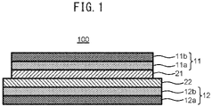
- the all-solid-state battery 100 comprises a first electrode layer 11, a first solid electrolyte layer 21, a second solid electrolyte layer 22, and a second electrode layer 12 in this order.
- the first solid electrolyte layer 21 has a first surface 21x
- the second solid electrolyte layer 22 has a second surface 22x that is in contact with the first surface 21x.
- a maximum height Rz 1 of the first surface 21x and a maximum height Rz 2 of the second surface 22x satisfy the following relation (1): 0.15 ⁇ Rz 1 /Rz 2 ⁇ 0.25
- the first electrode layer 11 may comprise an active material layer 11a and a current collector layer 11b.
- the first electrode layer 11 may be a positive electrode layer or a negative electrode layer.
- a superior effect can be expected particularly in the case of a positive electrode layer. That is, the first electrode layer 11 may comprise a positive electrode active material layer 11a, and may further comprise a positive current collector layer 11b.
- the positive electrode active material layer 11a contains at least a positive electrode active material.
- the positive electrode active material layer 11a may optionally contain a solid electrolyte, a binder, a conductive aid and etc., in addition to the positive electrode active material.
- a known positive electrode active material for an all-solid-state battery may be used as the positive electrode active material.
- the known active materials two materials having different potentials (charge/discharge potentials) for storing and releasing predetermined ions are selected, and the material exhibiting an electropositive potential and the material exhibiting an electronegative potential can be used as the positive electrode active material and the negative electrode active material, respectively.
- various lithium-containing composite oxides such as lithium cobalt oxide, lithium nickel oxide, LiNi 1/3 Co 1/3 Mn 1/3 O 2 , lithium manganese oxide, and spinel-based lithium compounds; and sulfur or sulfur compounds can be used as the positive electrode active material.
- One type of the positive electrode active material may be used alone, or two or more may be used as a mixture.
- the positive electrode active material layer 11a contains sulfur as the positive electrode active material, a more superior effect can be expected. It is considered that sulfur as a positive electrode active material has a large amount of expansion and contraction during charging and discharging, stress accompanying the expansion and contraction easily accumulates between the positive electrode active material layer and the solid electrolyte layer, and the stress is not relieved, whereby cracks are easily generated in the solid electrolyte layer.
- the propagation of cracks generated in the solid electrolyte layer is suppressed, and the short-circuit resistance of the all-solid-state battery is easily improved.
- a covering layer such as a lithium niobate layer, a lithium titanate layer, or a lithium phosphate layer may be provided.
- the positive electrode active material may be, for example, particulate, and the size thereof is not particularly limited.
- the particles of the positive electrode active material may be solid particles or hollow particles.
- the particles of the positive electrode active material may be primary particles or secondary particles of a plurality of agglomerated primary particles.
- the average particle diameter of the particles of the positive electrode active material may be, for example, 1 nm or more, 5 nm or more, or 10 nm or more, and may be 500 ⁇ m or less, 100 ⁇ m or less, 50 ⁇ m or less, or 30 ⁇ m or less.
- the average particle diameter referred herein is a particle diameter (median diameter, D50) at an integrated value of 50% in a volume-based particle size distribution determined by a laser diffraction/scattering method.
- a known solid electrolyte for an all-solid-state cell may be used as the solid electrolyte that can be contained in the positive electrode active material layer 11a.
- the solid electrolyte may be an inorganic solid electrolyte or an organic polymer electrolyte.
- an inorganic solid electrolyte has high ionic conductivity compared to an organic polymer electrolyte, and has excellent heat resistance compared to an organic polymer electrolyte.
- the inorganic solid electrolyte examples include oxide solid electrolytes such as lithium lanthanum zirconate, LiPON, Li 1+x Al x Ge 2-x (PO 4 ) 3 , Li-SiO-based glass, and Li-Al-S-O-based glass; and sulfide solid electrolytes such as Li 2 S, P 2 S 5 , Li 2 S-P 2 S 5 , Li 2 S-SiS 2 , LiI-Li 2 S-SiS 2 , LiI-Si 2 S-P 2 S 5 , Li 2 S-P 2 S 5 -LiI-LiBr, LiI-Li 2 S-P 2 S 5 , LiI-Li 2 S-P 2 O 5 , LiI-Li 3 PO 4 -P 2 S 5 , and Li 2 S-P 2 S 5 -GeS 2 .
- oxide solid electrolytes such as lithium lanthanum zirconate, LiPON, Li 1+x Al x Ge 2-
- a sulfide solid electrolyte has excellent performance.
- the solid electrolyte may be amorphous or crystalline.
- One type of the solid electrolyte may be used alone, or two or more may be used as a mixture.
- the solid electrolyte that can be contained in the positive electrode active material layer 11a may be particulate.
- the particles of the solid electrolyte may be primary particles or secondary particles of a plurality of agglomerated primary particles.
- the average particle diameter of the solid electrolyte may be, for example, 10 nm or more, 0.1 ⁇ m or more, 0.5 ⁇ m or more, or 1 ⁇ m or more, and may be 100 ⁇ m or less, 50 ⁇ m or less, 10 ⁇ m or less, or 5 ⁇ m or less.
- the binder that can be contained in the positive electrode active material layer 11a may be, for example, at least one selected from a butadiene rubber (BR)-based binder, a butylene rubber (IIR)-based binder, an acrylate butadiene rubber (ABR)-based binder, a styrene butadiene rubber (SBR)-based binder, a polyvinylidene fluoride (PVdF)-based binder, and a polytetrafluoroethylene (PTFE)-based binder.
- BR butadiene rubber
- IIR acrylate butadiene rubber
- ABR styrene butadiene rubber
- PVdF polyvinylidene fluoride
- PTFE polytetrafluoroethylene
- the conductive aid that can be contained in the positive electrode active material layer 11a may be, for example, at least one selected from carbon materials, such as acetylene black and Ketjen black, and metallic materials, such as nickel, aluminum, and stainless steel.
- the conductive aid may be, for example, particulate or fibrous, and the size thereof is not particularly limited.
- the content of each component of the positive electrode active material layer 11a may be the same as in the prior art.
- the positive electrode active material layer 11a may contain, for example, 10% by mass or greater and 90% by mass or less of the positive electrode active material, 0% by mass or greater and 60% by mass or less of the solid electrolyte, 0% by mass or greater and 30% by mass or less of the conductive aid, and optionally the binder as the balance.
- the shape of the positive electrode active material layer 11a may also be the same as in the prior art. From the viewpoint of being able to easily configure the all-solid-state battery 100, the positive electrode active material layer 11a may be sheet-like.
- the thickness of the positive electrode active material layer 11a is not particularly limited, but may be, for example, 0.1 ⁇ m or more and 2 mm or less. The lower limit may be 1 ⁇ m or more, and the upper limit may be 1 mm or less.
- the positive current collector layer 11b may be composed of a metal foil or a metal mesh. Particularly, a metal foil has excellent handleability.
- the positive current collector layer 11b may be formed of a plurality of metal foils. Examples of a metal constituting the positive current collector layer 11b include Cu, Ni, Cr, Au, Pt, Ag, Al, Fe, Ti, Zn, Co, and stainless steel. Particularly, from the viewpoint of ensuring oxidation resistance, the positive current collector layer 11b may contain Al.
- the positive current collector layer 11b may have some coating layer on a surface thereof for the purpose of adjusting resistance.
- the positive current collector layer 11b when the positive current collector layer 11b is formed of a plurality of metal foils, the plurality of metal foils may have some layer therebetween.
- the thickness of the positive current collector layer 11b is not particularly limited, but may be, for example, 0.1 ⁇ m or more or 1 ⁇ m or more, and 1 mm or less or 100 ⁇ m or less.
- the first solid electrolyte layer 21 is disposed between the first electrode layer 11 and the second solid electrolyte layer 22, and may be in contact with both. That is, the first solid electrolyte layer 21 may have a first surface 21x in contact with the second solid electrolyte layer 22, and may have a fifth surface 21y in contact with the first electrode layer 11.
- the first solid electrolyte layer 21 contains at least a solid electrolyte.
- the first solid electrolyte layer 21 may contain a binder and etc. in addition to the solid electrolyte.
- the solid electrolyte contained in the first solid electrolyte layer 21 may be the same as or different from the solid electrolyte that can be contained in the positive electrode active material layer 11a.
- the solid electrolyte may be the above inorganic solid electrolyte. Particularly, the above sulfide solid electrolyte has excellent performance.
- the solid electrolyte may be amorphous or crystalline. One type of the solid electrolyte may be used alone, or two or more may be used as a mixture.
- the solid electrolyte contained in the first solid electrolyte layer 21 may be particulate.
- the average particle diameter of the solid electrolyte may be, for example, 10 nm or more, 0.1 ⁇ m or more, 0.5 ⁇ m or more, or 1 ⁇ m or more, and may be 100 ⁇ m or less, 50 ⁇ m or less, 10 ⁇ m or less, or 5 ⁇ m or less.
- the binder that can be contained in the first solid electrolyte layer 21 may be the same as or different from the binder that can be contained in the above positive electrode active material layer 11a, and may be at least one selected from, for example, a butadiene rubber (BR)-based binder, a butylene rubber (IIR)-based binder, an acrylate butadiene rubber (ABR)-based binder, a styrene butadiene rubber (SBR)-based binder, a polyvinylidene fluoride (PVdF)-based binder, and a polytetrafluoroethylene (PTFE)-based binder.
- BR butadiene rubber
- IIR acrylate butadiene rubber
- SBR styrene butadiene rubber
- PVdF polyvinylidene fluoride
- PTFE polytetrafluoroethylene
- the contents of the solid electrolyte and the binder in the first solid electrolyte layer 21 are not particularly limited.
- the first solid electrolyte layer 21 may contain, for example, 80% by mass or greater or 90% by mass or greater of the solid electrolyte and 20% by mass or less or 10% by mass or less of the binder. Particularly, when the first solid electrolyte layer 21 contains the binder in an amount of 0.6% by mass or greater and 10% by mass or less, high performance is easily ensured.
- the first solid electrolyte layer 21 may be, for example, sheet-like.
- the thickness of the first solid electrolyte layer 21 is not particularly limited, but may be, for example, 0.1 ⁇ m or more and 2 mm or less. The lower limit may be 1 ⁇ m or more, and the upper limit may be 1 mm or less.
- the first solid electrolyte layer 21 may be thicker or thinner than the second solid electrolyte layer 22 described later. It is considered that thicker one is more effective.
- the second solid electrolyte layer 22 is disposed between the first solid electrolyte layer 21 and the second electrode layer 12, and may be in contact with both. That is, the second solid electrolyte layer 22 may have a second surface 22x in contact with the first solid electrolyte layer 21, and may have a third surface 22y in contact with the second electrode layer 12.
- the second solid electrolyte layer 22 contains at least a solid electrolyte.
- the second solid electrolyte layer 22 may contain a binder and etc. in addition to the solid electrolyte.
- the solid electrolyte contained in the second solid electrolyte layer 22 may be the same as or different from the solid electrolyte that can be contained in the positive electrode active material layer 11a or the first solid electrolyte layer 21 above. Particularly, it is preferable that the same solid electrolyte as the one contained in the first solid electrolyte layer 21 be used.
- the solid electrolyte may be the above inorganic solid electrolyte. Particularly, the above sulfide solid electrolyte has excellent performance.
- the solid electrolyte may be amorphous or crystalline. One type of the solid electrolyte may be used alone, or two or more may be used as a mixture.
- the solid electrolyte contained in the second solid electrolyte layer 22 may be particulate.
- the average particle diameter of the solid electrolyte may be, for example, 10 nm or more, 0.1 ⁇ m or more, 0.5 ⁇ m or more, or 1 ⁇ m or more, and may be 100 ⁇ m or less, 50 ⁇ m or less, 10 ⁇ m or less, or 5 ⁇ m or less.
- the solid electrolyte contained in the first solid electrolyte layer 21 and the electrolyte contained in the second solid electrolyte layer 22 may have substantially the same particle diameter.
- the ratio D 1 /D 2 between the average particle diameter D 1 of the solid electrolyte contained in the first solid electrolyte layer 21 and the average particle diameter D 2 of the solid electrolyte contained in the second solid electrolyte layer 22 may be 0.5 or greater, 0.7 or greater, or 0.9 or greater, and may be 1.5 or less, 1.3 or less, or 1.1 or less.
- the binder that can be contained in the second solid electrolyte layer 22 may be the same as or different from the binder that can be contained in the positive electrode active material layer 11a or the first solid electrolyte layer 21 above, and may be at least one selected from, for example, a butadiene rubber (BR)-based binder, a butylene rubber (IIR)-based binder, an acrylate butadiene rubber (ABR)-based binder, a styrene butadiene rubber (SBR)-based binder, a polyvinylidene fluoride (PVdF)-based binder, and a polytetrafluoroethylene (PTFE)-based binder.
- BR butadiene rubber
- IIR acrylate butadiene rubber
- SBR styrene butadiene rubber
- PVdF polyvinylidene fluoride
- PTFE polytetrafluoroethylene
- the contents of the solid electrolyte and the binder in the second solid electrolyte layer 22 are not particularly limited.
- the second solid electrolyte layer 22 may contain, for example, 80% by mass or greater or 90% by mass or greater of the solid electrolyte and 20% by mass or less or 10% by mass or less of the binder. Particularly, when the second solid electrolyte layer 22 contains the binder in an amount of 0.6% by mass or greater and 10% by mass or less, high performance is easily ensured.
- the second solid electrolyte layer 22 may be, for example, sheet-like.
- the thickness of the second solid electrolyte layer 22 is not particularly limited, but may be, for example, 0.1 ⁇ m or more and 2 mm or less.
- the lower limit may be 1 ⁇ m or more, and the upper limit may be 1 mm or less.
- the second solid electrolyte layer 22 may be thicker or thinner than the first solid electrolyte layer 21 described above. It is considered that thinner one is more effective.
- the area of the surface 22x or 22y of the second solid electrolyte layer 22 may be larger than the area of the surface 11x of the first electrode layer 11 or may be larger than the area of the surface 21x or 21y of the first solid electrolyte layer 21, as shown in FIGS. 1 and 2 .
- the second electrode layer 12 may comprise an active material layer 12a and a current collector layer 12b.
- the second electrode layer 12 may be a positive electrode layer or a negative electrode layer.
- a superior effect can be expected particularly in the case of a negative electrode layer. That is, the second electrode layer 12 may comprise a negative electrode active material layer 12a, and may further comprise a negative current collector layer 12b.
- the negative electrode active material layer 12a contains at least a negative electrode active material.
- the negative electrode active material layer 12a may optionally contain a solid electrolyte, a binder, a conductive aid and etc., in addition to the negative electrode active material.
- a known active material may be used as the negative electrode active material.
- silicon-based active materials such as Si, Si alloys, and silicon oxides
- carbon-based active materials such as graphite or hard carbon
- various oxide-based active materials such as lithium titanate
- metallic lithium pure lithium or a lithium alloy
- the metallic lithium as the negative electrode active material is softer compared to other active materials. So, when a high pressure is applied to bring the metallic lithium and the second solid electrolyte layer 22 into close contact with each other, there is a risk of the metallic lithium entering the gaps in the second solid electrolyte layer 22 and reaching the positive electrode side.
- the negative electrode active material layer 12a and the second solid electrolyte layer 22 are easily secured at the interface between the negative electrode active material layer 12a and the second solid electrolyte layer 22, even when the negative electrode active material layer 12a contains metallic lithium as the negative electrode active material. Consequently, the growth of dendrites caused by poor contact during charging and discharging of the battery is easily suppressed.
- the negative electrode active material may be, for example, particulate, or may be foil-like as described later.
- the solid electrolyte, the binder, and the conductive aid that can be contained in the negative electrode active material layer 12a can be appropriately selected and used from ones exemplified as those that can be contained in the positive electrode active material layer 11a.
- the content of each component of the negative electrode active material layer 12a may be the same as in the prior art.
- the negative electrode active material layer 12a may contain, for example, 10% by mass or greater and 100% by mass or less of the negative electrode active material, 0% by mass or greater and 60% by mass or less of the solid electrolyte, 0% by mass or greater and 30% by mass or less of the conductive aid, and optionally the binder as the balance.
- the shape of the negative electrode active material layer 12a may also be the same as in the prior art. From the viewpoint of being able to easily configure the all-solid-state battery 100, the negative electrode active material layer 12a may be sheet-like.
- the thickness of the negative electrode active material layer 12a is not particularly limited, but may be, for example, 0.1 ⁇ m or more and 2 mm or less. The lower limit may be 1 ⁇ m or more, and the upper limit may be 1 mm or less.
- a layer composed of metallic lithium for example, a metallic lithium foil
- the area of the surface 12x of the second electrode layer 12 may be larger than the area of the surface 11x of the first electrode layer 11 or may be larger than the area of the surface 21x or 21y of the first solid electrolyte layer 21, as shown in FIGS. 1 and 2 .
- the negative current collector layer 12b may be composed of a metal foil or a metal mesh or composed of a carbon sheet. Particularly, a metal foil or a carbon sheet has excellent handleability.
- the negative current collector layer 12b may be formed of a plurality of metal foils or carbon sheets. Examples of a metal constituting the negative current collector layer 12b include Cu, Ni, Cr, Au, Pt, Ag, Al, Fe, Ti, Zn, Co, and stainless steel. Particularly, from the viewpoint of ensuring reduction resistance and the viewpoint of inhibiting alloying with lithium, the negative current collector layer 12b may contain at least one metal selected from Cu, Ni, and stainless steel or may be formed of a carbon sheet.
- the negative current collector layer 12b may have some coating layer on a surface thereof for the purpose of adjusting resistance.
- the negative current collector layer 12b is formed of a plurality of metal foils, the plurality of metal foils may have some layer therebetween.
- the thickness of the negative current collector layer 12b is not particularly limited, but may be, for example, 0.1 ⁇ m or more or 1 ⁇ m or more, and 1 mm or less or 100 ⁇ m or less.
- the first electrode layer 11 may have a sixth surface 11x in contact with the first solid electrolyte layer 21.
- the first solid electrolyte layer 21 may have a first surface 21x in contact with the second solid electrolyte layer 22 and may have a fifth surface 21y in contact with the sixth surface 11x of the first electrode layer 11.
- the second solid electrolyte layer 22 may have a second surface 22x in contact with the first surface 21x of the first solid electrolyte layer 21 and may have a third surface 22y in contact with the second electrode layer 12.
- the second electrode layer 12 may have a fourth surface 12x in contact with the third surface 22y of the second solid electrolyte layer 22.
- Each surface may have a predetermined surface roughness. Hereinafter, the relationship of each surface roughness will be described.
- a ratio Rz 1 /Rz 2 is 0.15 or greater and 0.25 or less.
- the ratio Rz 1 /Rz 2 is considered to express the state of contact between the first solid electrolyte layer 21 and the second solid electrolyte layer 22. According to new findings of the present inventor, when the ratio Rz 1 /Rz 2 is excessively small, the difference in surface roughness between the first solid electrolyte layer 21 and the second solid electrolyte layer 22 is excessively large.
- the first solid electrolyte layer 21 and the second solid electrolyte layer 22 easily conform to each other.
- cracks are generated in one of the first solid electrolyte layer 21 and the second solid electrolyte layer 22, cracks are also easily generated in the other layer, and cracks generated in one layer easily propagate to the other layer.
- it is difficult to improve the short-circuit resistance of the all-solid-state battery.
- the specific value of the maximum height Rz 1 of the first surface 21x of the first solid electrolyte layer 21 in the all-solid-state battery 100 is not particularly limited, but may be, for example, 0.1 ⁇ m or more, 0.2 ⁇ m or more, or 0.3 ⁇ m or more, and may be 3.0 ⁇ m or less, 2.0 ⁇ m or less, 1.0 ⁇ m or less, 0.9 ⁇ m or less, 0.8 ⁇ m or less, or 0.7 ⁇ m or less.
- the specific value of the maximum height Rz 2 of the second surface 22x of the second solid electrolyte layer 22 in the all-solid-state battery 100 is not particularly limited, but may be, for example, 0.5 ⁇ m or more, 0.8 ⁇ m or more, 1.0 ⁇ m or more, or 1.5 ⁇ m or more, and may be 5.0 ⁇ m or less, 4.0 ⁇ m or less, 3.0 ⁇ m or less, or 2.0 ⁇ m or less.
- the second solid electrolyte layer 22 may have a third surface 22y on the opposite side of the second surface 22x, and the second electrode layer 12 may have a fourth surface 12x in contact with the third surface 22y.
- the maximum height Rz 3 of the third surface 22y and the maximum height Rz 4 of the fourth surface 12x may satisfy the following relation (2) or (3). 0.45 ⁇ Rz 3 /Rz 4 ⁇ 1.00 0.45 ⁇ Rz 4 /Rz 3 ⁇ 1.00
- the upper limit of the ratio Rz 3 /Rz 4 or Rz 4 /Rz 3 is not particularly limited, but may be 1.00 or less as described above, or may be 0.90 or less, 0.80 or less, 0.70 or less, 0.60 or less, or 0.50 or less.
- the specific value of the maximum height Rz 3 of the third surface 22y of the second solid electrolyte layer 22 in the all-solid-state battery 100 is not particularly limited, but may be, for example, 0.1 ⁇ m or more, 0.3 ⁇ m or more, 0.5 ⁇ m or more, 0.8 ⁇ m or more, or 1.0 ⁇ m or more, and may be 5.0 ⁇ m or less, 4.0 ⁇ m or less, 3.0 ⁇ m or less, or 2.0 ⁇ m or less.
- the specific value of the maximum height Rz 4 of the fourth surface 12x of the second electrode layer 12 is not particularly limited, but may be, for example, 0.1 ⁇ m or more, 0.3 ⁇ m or more, 0.5 ⁇ m or more, 0.8 ⁇ m or more, or 1.0 ⁇ m or more, and may be 5.0 ⁇ m or less, 4.0 ⁇ m or less, 3.0 ⁇ m or less, or 2.0 ⁇ m or less.
- the first solid electrolyte layer 21 may have a fifth surface 21y on the opposite side of the first surface 21x, and the first electrode layer 11 may have a sixth surface 11x in contact with the fifth surface 21y.
- the maximum height Rz 5 of the fifth surface 21y and the maximum height Rz 6 of the sixth surface 11x may satisfy the following relation (4) or (5). Consequently, the unevenness of the surface of the first solid electrolyte layer 21 and the unevenness of the surface of the first electrode layer 11 are engaged with each other, the contact area between the first solid electrolyte layer 21 and the first electrode layer 11 can be increased, and ionic conduction paths between the first solid electrolyte layer 21 and the first electrode layer 11 can be easily secured. 0.45 ⁇ Rz 5 /Rz 6 ⁇ 1.00 0.45 ⁇ Rz 6 /Rz 5 ⁇ 1.00
- the maximum height Rz of the surface of each layer can be defined by SEM observation of the cross-section of the all-solid-state battery.
- a cross-section near the interface between the first solid electrolyte layer 21 and the second solid electrolyte layer 22 of the all-solid-state battery 100 is observed by SEM, and a two-dimensional image of the cross-section is acquired.
- the two-dimensional image comprises five or more convex portions on the surface of each of the first solid electrolyte layer 21 and the second solid electrolyte layer 22. Of the convex portions, two peaks P1 and P2 are specified, and a straight line L1 connecting the P1 and P2 is drawn.
- the surface of each layer is exposed by peeling off each layer from the all-solid-state battery, and then Rz may be measured for the exposed surface in accordance with JIS B0601:2001.
- the surface of each layer is exposed; then, the unevenness of the surface is molded with a resin; Rz may be measured for the resin, to which the same unevenness as the surface is substantially transferred, in accordance with JIS B0601:2001, and this may be considered as Rz of the surface of each layer.
- Rz can be determined for a sample cut into a size of 10 mm ⁇ 10 mm under the measurement conditions of a measurement length of 8 mm and a cut-off value of 0.5 mm, using an SE-600 manufactured by Kosaka Laboratory Ltd.
- the Rz measured by image analysis described above and the Rz measured according to the JIS standard either one may satisfy the above relations.
- the maximum height Rz of the surface of each layer substantially correlates with the arithmetic mean roughness Ra of the surface of each layer. That is, it is considered that the state of unevenness over the entire surface of each layer can be expressed by defining the maximum height Rz of the surface of each layer.
- the ratios and specific values of the arithmetic mean roughness Ra of the surfaces 11x, 12x, 21x, 21y, 22x, and 22y of the corresponding layers 11, 12, 21, and 22 are not particularly limited.
- a ratio Ra/Rz may be 0.1 or greater and 0.2 or less.
- the all-solid-state battery 100 may comprise at least the layers described above, and may also comprise additional components.
- the components described hereinafter are examples of other members which can be contained in the all-solid-state battery 100.
- each of the above layers may be housed inside an outer packaging. More specifically, a portion excluding a tab or a terminal for extracting power from the all-solid-state battery 100 to an external portion may be housed inside the outer packaging. Any known outer packaging for a battery can be adopted as the outer packaging. For example, a laminate film may be used as the outer packaging.
- a plurality of all-solid-state batteries 100 may be electrically connected and optionally stacked to form a battery pack (assembled battery). In this case, the battery pack may be housed inside a known battery case.
- each of the above layers may be sealed with a resin.
- a resin for example, at least a side surface (a surface along a laminating direction) of the laminate composed of each of the layers may be sealed with the resin. Consequently, contamination of the internal portion of each layer by moisture is easily suppressed.
- a known thermosetting or thermoplastic resin can be adopted as the sealing resin.
- the all-solid-state battery 100 may comprise a restraining member for restraining each layer in a laminating direction.
- a restraining pressure is usually smaller than the pressure P 1 or the pressure P 2 described later, and may be, for example, 50 MPa or less, 30 MPa or less, or 10 MPa or less, and may be 0.1 MPa or more or 1.0 MPa or more.
- the technique of the present disclosure also has an aspect as a manufacturing method for an all-solid-state battery.
- the manufacturing method for an all-solid-state battery according to one embodiment comprises:
- the first solid electrolyte layer 21 is formed on the surface of the substrate 31 to obtain the transfer material 41.
- the substrate 31 may be of any material that can be peeled off from the first solid electrolyte layer 21 after a pressure P 1 is applied in the step S2 described later.
- a metal foil or a resin film can be adopted as the substrate 31.
- the method of forming the first solid electrolyte layer 21 on the surface of the substrate 31 is not particularly limited.
- the transfer material 41 may be obtained by coating the surface of the substrate 31 with a slurry containing a material constituting the first solid electrolyte layer 21 and then drying the slurry.
- the transfer material 41 may be obtained by dry-molding a material constituting the first solid electrolyte layer 21 together with the substrate 31.
- the transfer material 41 and the first electrode layer 11 are laminated together and a pressure P 1 is then applied in a laminating direction.
- the first electrode layer 11 may comprise an active material layer 11a and a current collector layer 11b, as described above.
- the first electrode layer 11 may be obtained by coating the surface of the current collector layer 11b with a slurry containing a material constituting the active material layer 11a and then drying the slurry.
- the first electrode layer 11 may be obtained by dry-molding a material constituting the active material layer 11a together with the current collector layer 11b.
- the first solid electrolyte layer 21 of the transfer material 41 and the active material layer 11a of the first electrode layer 11 are stacked and laminated together, and a pressure P 1 is applied in a laminating direction to bring the first solid electrolyte layer 21 and the active material layer 11a into close contact with each other at an interface therebetween.
- the pressure P 1 may be a pressure that can plastically deform the solid electrolyte contained in the first solid electrolyte layer 21.
- the pressure P 1 may be more than 100 MPa, 200 MPa or more, 300 MPa or more, 400 MPa or more, 500 MPa or more, or 600 MPa or more.
- the upper limit of the pressure P 1 is not particularly limited as long as the pressure does not damage each layer.
- the method of applying pressure in the step S2 is not particularly limited, and various methods of applying pressure such as CIP, HIP, roll pressing, uniaxial pressing, or die pressing can be adopted.
- applying pressure in a laminating direction means applying a pressure P 1 or a pressure P 2 at least in a laminating direction, and may include a pressure in a direction other than a laminating direction together with the pressure P 1 or the pressure P 2 in a laminating direction.
- the substrate 31 is removed by peeling off from the transfer material 41 to obtain the first laminate 51 comprising the first electrode layer 11 and the first solid electrolyte layer 21.
- the second electrode layer 12 is coated with a material 22a constituting the second solid electrolyte layer 22 to obtain a second laminate 52 comprising the second electrode layer 12 and the second solid electrolyte layer 22.
- the second electrode layer 12 may comprise an active material layer 12a and a current collector layer 12b, as described above.
- the second electrode layer 12 may be obtained by coating the surface of the current collector layer 12b with a slurry containing a material constituting the active material layer 12a and then drying the slurry.
- the second electrode layer 12 may be obtained by dry-molding a material constituting the active material layer 12a together with the current collector layer 12b.
- the second electrode layer 12 may be obtained by affixing a metallic lithium foil as the active material layer 12a on a surface of a metal foil as the current collector layer 12b.
- the second laminate 52 is obtained by, for example, coating the surface of the active material layer 12a of the second electrode layer 12 with a slurry containing a material constituting the second solid electrolyte layer 22 and then drying the slurry.
- a pressure may or may not be applied to the second laminate 52.
- the applied pressure is smaller than the pressure P 1 above.
- a layer containing metallic lithium as the active material layer 12a is adopted, since the metallic lithium is soft, there is a risk of the metallic lithium excessively permeating into the internal portion of the second solid electrolyte layer 22 when a large pressure is applied to the second laminate 52.
- the second solid electrolyte layer 22 and the second electrode layer 12 can be brought into close contact with each other in the second laminate 52 without applying a pressure to the second laminate 52, and the ratio Rz 3 /Rz 4 or Rz 4 /Rz 3 , as described above, can be easily achieved after carrying out the step S4 described later.
- the maximum height Rz 2 of the second surface 22x of the second solid electrolyte layer 22 is equivalent to the maximum height Rz 1 of the first surface 21x of the first solid electrolyte layer 21, and it is difficult to satisfy the ratio Rz 1 /Rz 2 described above.
- the active material layer 12a of the second electrode layer 12 contains the soft metallic lithium, transferring the second solid electrolyte layer 22 to the surface of the active material layer 12a is difficult in the first place.
- the first laminate 51 and the second laminate 52 are laminated together and a pressure P 2 smaller than the pressure P 1 is then applied in a laminating direction to obtain an all-solid-state battery 100 comprising the first electrode layer 11, the first solid electrolyte layer 21, the second solid electrolyte layer 22, and the second electrode layer 12 in this order.
- the pressure may be applied to the extent that the first laminate 51 and the second laminate 52 are brought into moderate contact with each other.
- metallic lithium when metallic lithium is adopted as the active material in the electrode layer, there is a concern of the metallic lithium being unnecessarily deformed by the excessive application of pressure, permeating into the solid electrolyte layer, and causing a short circuit. Further, the unevenness of the surface of the second surface 22x of the second solid electrolyte layer 22 is eliminated by the excessive application of pressure, and it is difficult to satisfy the ratio Rz 1 /Rz 2 as described above.
- the pressure P 2 in the step S4 should be smaller than the pressure P 1 in the step S2.
- the pressure P 2 may be less than 200 MPa, 180 MPa or less, 150 MPa or less, 120 MPa or less, or 100 MPa or less.
- the lower limit of the pressure P 2 is not particularly limited as long as the pressure sufficiently ensures contact at the interface of the cell material.
- the method of applying pressure in the step S4 is not particularly limited, and various methods of applying pressure such as CIP, HIP, roll pressing, uniaxial pressing, or die pressing can be adopted.
- the manufacturing method for an all-solid-state battery may comprise a step of housing the all-solid-state battery obtained as described above inside an outer packaging and a step of attaching members necessary for a battery, such as a terminal. Description of any obvious step in the manufacturing method for an all-solid-state battery is omitted.
- the kneaded powder was placed in the pot with the zirconia balls, and a process of mechanical milling at 500 rpm for 1 h, pausing for 15 min, mechanical milling in reverse rotation at 500 rpm for 1 h, and pausing for 15 min was repeated for 48 h to obtain the positive electrode mixture.
- a mesitylene solution containing 5% by mass of SBR and mesitylene were charged in a container made of polypropylene and mixed for 3 min by a shaker.
- the positive electrode mixture (S 8 -P 2 S 5 /C) was charged in the container, and then mixed for 3 min by a shaker and for 30 s by an ultrasonic disperser, each repeated twice.
- a positive electrode mixture slurry obtained immediately after mixing for 5 s by the ultrasonic disperser was coated an Al foil as the positive current collector layer using a doctor blade having a coating gap of 250 ⁇ m. After visually confirming that the surface coated with the positive electrode mixture was dried, the surface was further dried on a hot plate at 100 °C for 30 min to obtain a positive electrode layer as a first electrode layer.
- a heptane solution containing 5% by mass of ABR, heptane, and butyl butyrate were charged in a container made of polypropylene and mixed for 3 min by a shaker.
- a transfer material composed of a substrate and a solid electrolyte layer was obtained by the same method as in the production of the first solid electrolyte layer.
- the amount of ABR contained in the solid electrolyte layer was 0.6% by mass.
- the transfer material was stacked on the surface of the positive electrode layer and pressed at 600 MPa.
- the substrate was then peeled off from the transfer material to transfer the first solid electrolyte layer to the surface of the positive electrode layer, and a first laminate comprising a positive current collector layer, a positive electrode active material layer, and a first solid electrolyte layer in this order was obtained.
- a new transfer material was stacked on the surface of the first solid electrolyte layer of the first laminate and pressed at 600 MPa.
- the substrate was then peeled off from the transfer material, and a second laminate comprising a positive current collector layer, a positive electrode active material layer, a first solid electrolyte layer, and a second solid electrolyte layer in this order was obtained.
- a metallic lithium foil as a negative electrode active material layer and an Ni foil as a negative current collector layer were laminated together on the surface of the second solid electrolyte layer of the second laminate and pressed at 100 MPa to obtain an all-solid-state battery comprising the positive current collector layer, the positive electrode active material layer, the first solid electrolyte layer, the second solid electrolyte layer, the negative electrode active material layer, and the negative current collector layer in this order.
- the all-solid-state battery thus obtained was sealed in a laminate film and restrained at 10 MPa in a laminating direction for evaluation.
- a positive electrode layer as the first electrode layer and a transfer material of the first solid electrolyte layer were produced in the same manner as in Comparative Example 1. Thereafter, the transfer material was stacked on the surface of the positive electrode layer and pressed at 600 MPa. The substrate was then peeled off from the transfer material to transfer the first solid electrolyte layer to the surface of the positive electrode layer, and a first laminate comprising a positive current collector layer, a positive electrode active material layer, and a first solid electrolyte layer in this order was obtained.
- a Li foil (thickness of 70 ⁇ m) was affixed to the surface of a Ni foil as a negative current collector layer to obtain a negative electrode layer as a second electrode layer.
- a heptane solution containing 5% by mass of ABR, heptane, and butyl butyrate were charged in a container made of polypropylene and mixed for 3 min by a shaker.
- the first laminate and the second laminate were laminated and pressed together at 100 MPa to obtain an all-solid-state battery comprising the positive current collector layer, the positive electrode active material layer, the first solid electrolyte layer, the second solid electrolyte layer, the negative electrode active material layer, and the negative current collector layer in this order.
- the all-solid-state battery thus obtained was sealed in a laminate film and restrained at 10 MPa in a laminating direction for evaluation.
- the all-solid-state battery was produced in the same manner as in Example 1.
- the all-solid-state battery was produced in the same manner as in Example 1.
- the maximum height Rz of the surface of each layer at the interface between the first solid electrolyte layer and the second solid electrolyte layer was measured for each of the all-solid-state battery according to the Examples and Comparative Examples.
- the measurement method of Rz is as described above. The results are shown in Table 1 below.
- the all-solid-state battery was placed and heat homogenized in an isothermal bath at 60 °C for 3 h. Thereafter, discharging and charging were carried out at a current density of 0.46 mA/cm 2 .
- the cut-off voltage was 1.5 to 3.1 V.
- the maximum charge capacity obtained before a short circuit was measured, and this capacity was used as the "short-circuit resistance capacity" to evaluate the short-circuit resistance of the all-solid-state battery. The larger the short-circuit resistance capacity, the more superior the short-circuit resistance. The results are shown in Table 1 below.
- Example 1 Comparisons can be made between Comparative Example 1 and Example 1, between Comparative Example 2 and Example 2, and between Comparative Example 3 and Example 3, based on the amount of binder.
- Example 4 is considered to be a variation of Example 3.
- the all-solid-state battery has excellent short-circuit resistance when the ratio Rz 1 /Rz 2 between the maximum height Rz 1 of the surface of the first solid electrolyte layer and the maximum height Rz 2 of the surface of the second solid electrolyte layer is within the range of 0.15 or greater and 0.25 or less (Examples 1 to 4).
- the short-circuit resistance of the all-solid-state battery decreases as the ratio Rzi/Rz2 approaches 1.00 (Comparative Examples 1 to 3). It is considered to be due to the following mechanism.
- the present inventor has also confirmed the following by experimentation.
- the first laminate and the second laminate are both produced by a coating method, and then the first laminate and the second laminate are stacked and pressed at 100 MPa, in addition to the ratio Rz 1 /Rz 2 at the interface between the first solid electrolyte layer and the second solid electrolyte layer approaching 1.00, it is difficult to secure ionic conduction paths at the interface between the positive electrode layer and the first solid electrolyte layer, leading to a small maximum capacity as a battery. As a result, the short-circuit resistance capacity is small. In this regard, there is merit in producing one of the first laminate and the second laminate by a transfer method.
- the short-circuit resistance of the all-solid-state battery can be improved when the technique of the present disclosure is applied to all-solid-state batteries other than the lithium-sulfur battery.
- the technique of the present disclosure focuses on the state of the interface between the first solid electrolyte layer and the second solid electrolyte layer, the first electrode layer and the second electrode layer can be freely changed.
- an active material other than sulfur may be adopted as the positive electrode active material, and an active material other than metallic lithium (pure lithium and lithium alloys) may be adopted as the negative electrode active material.
- the technique of the present disclosure can also be applied to solve specific problems (such as softness and the inability to transfer a solid electrolyte layer) that occur when metallic lithium is used as the negative electrode active material.
- Each of the above Examples and Comparative Examples embodies an all-solid-state battery comprising a positive electrode layer as the first electrode layer and a negative electrode layer as the second electrode layer.
- the technique of the present disclosure demonstrates the same effect when applied to an all-solid-state battery comprising a negative electrode layer as the first electrode layer and a positive electrode layer as the second electrode layer.
- an all-solid-state battery having the following features (1) and (2) is less likely to have cracks propagate in the solid electrolyte layer and has excellent short-circuit resistance.
Landscapes
- Chemical & Material Sciences (AREA)
- Chemical Kinetics & Catalysis (AREA)
- Electrochemistry (AREA)
- General Chemical & Material Sciences (AREA)
- Engineering & Computer Science (AREA)
- Manufacturing & Machinery (AREA)
- Inorganic Chemistry (AREA)
- General Physics & Mathematics (AREA)
- Condensed Matter Physics & Semiconductors (AREA)
- Physics & Mathematics (AREA)
- Materials Engineering (AREA)
- Secondary Cells (AREA)
- Battery Electrode And Active Subsutance (AREA)
Abstract
An all-solid-state cell, having improved short-circuit resistance, comprises a first electrode layer, a first solid electrolyte layer, a second solid electrolyte layer, and a second electrode layer in this order, wherein the first solid electrolyte layer has a first surface, the second solid electrolyte layer has a second surface in contact with the first surface, and a maximum height Rz<sub>1</sub> of the first surface and a maximum height Rz<sub>2</sub> of the second surface satisfy the following relation (1): 0.15≤Rz1/Rz2≤0.25
Description
- The present application discloses an all-solid-state battery and a manufacturing method for an all-solid-state battery.
- PTL 1 discloses a technique for reducing pinholes which penetrate between a positive electrode layer and a negative electrode layer of an all-solid-state battery by interposing two solid electrolyte layers between the positive electrode layer and the negative electrode layer. In addition, PTL 2 discloses a technique for improving the safety and reliability of an all-solid-state battery using metallic lithium as a negative electrode active material by interposing two or more types of solid electrolytes between the positive electrode layer and the negative electrode layer and adjusting the material and ionic conductivity of each solid electrolyte layer.
-
- [PTL 1]
WO 2014/010043 A1 - [PTL 2]
JP 2004-206942 A - According to new findings of the present inventors, even when two solid electrolyte layers are interposed between the positive electrode layer and the negative electrode layer of an all-solid-state battery, there is a risk that if stress is applied to a solid electrolyte layer due to expansion or contraction of the active material during charging and discharging of the all-solid-state battery and cracks are generated in the solid electrolyte layer, the cracks may propagate from one solid electrolyte layer to the other solid electrolyte layer and cause a short circuit. In this regard, there is room for improvements in the prior art regarding the suppression of the propagation of cracks in the solid electrolyte layer to improve the short-circuit resistance of the all-solid-state battery.
- As a means for solving the above problem, the present application discloses
- an all-solid-state battery, comprising a first electrode layer, a first solid electrolyte layer, a second solid electrolyte layer, and a second electrode layer in this order, wherein
- the first solid electrolyte layer has a first surface,
- the second solid electrolyte layer has a second surface in contact with the first surface, and
- a maximum height Rz1 of the first surface and a maximum height Rz2 of the second surface satisfy a relation (1) below:

- In the all-solid-state battery of the present disclosure,
- the second solid electrolyte layer may have a third surface on an opposite side of the second surface,
- the second electrode layer may have a fourth surface in contact with the third surface, and
- a maximum height Rz3 of the third surface and a maximum height Rz4 of the fourth surface may satisfy a relation (2) or (3) below:


- In the all-solid-state battery of the present disclosure,
- the first electrode layer may comprise a positive electrode active material layer, and
- the second electrode layer may comprise a negative electrode active material layer.
- In the all-solid-state battery of the present disclosure,
the negative electrode active material layer may contain metallic lithium as a negative electrode active material. - In the all-solid-state battery of the present disclosure,
the positive electrode active material layer may contain sulfur as a positive electrode active material. - As a means for solving the above problem, the present application discloses
a manufacturing method for an all-solid-state battery, comprising: - forming a first solid electrolyte layer on a surface of a substrate to obtain a transfer material;
- laminating the transfer material and a first electrode layer together, then applying a pressure P1 in a laminating direction, and transferring the first solid electrolyte layer on the transfer material to the first electrode layer to obtain a first laminate comprising the first electrode layer and the first solid electrolyte layer;
- coating a second electrode layer with a material constituting a second solid electrolyte layer to obtain a second laminate comprising the second electrode layer and the second solid electrolyte layer; and
- laminating the first laminate and the second laminate together and then applying a pressure P2 smaller than the pressure P1 in a laminating direction to obtain an all-solid-state battery comprising the first electrode layer, the first solid electrolyte layer, the second solid electrolyte layer, and the second electrode layer in this order.
- In the manufacturing method of the present disclosure,
- the first electrode layer may comprise a positive electrode active material layer, and
- the second electrode layer may comprise a negative electrode active material layer.
- In the manufacturing method of the present disclosure,
the negative electrode active material layer may contain metallic lithium as a negative electrode active material. - In the manufacturing method of the present disclosure,
the positive electrode active material layer may contain sulfur as a positive electrode active material. - In the all-solid-state battery of the present disclosure, even when cracks are generated in one of the first solid electrolyte layer and the second solid electrolyte layer, the propagation of cracks to the other layer is easily suppressed, and excellent short-circuit resistance is easily ensured.
-
-
FIG. 1 schematically shows a configuration of the all-solid-state battery 100. -
FIG. 2 schematically shows a disassembled configuration of the all-solid-state battery 100. -
FIG. 3 schematically shows the measurement method of the maximum height Rz of a surface of a solid electrolyte layer. -
FIG. 4 shows an example of the flow of the manufacturing method for the all-solid-state battery 100. -
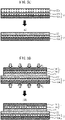
FIG. 5A schematically shows a configuration of the transfer material obtained by step S1. -
FIG. 5B schematically shows the flow of step S2 and a configuration of the first laminate obtained by the step S2. -
FIG. 5C schematically shows the flow of step S3 and a configuration of the second laminate obtained by the step S3. -
FIG. 5D schematically shows the flow of step S4 and a configuration of the all-solid-state battery obtained by the step S4. - As shown in
FIGS. 1 and2 , the all-solid-state battery 100 according to one embodiment comprises afirst electrode layer 11, a firstsolid electrolyte layer 21, a secondsolid electrolyte layer 22, and asecond electrode layer 12 in this order. As shown inFIG. 2 , the firstsolid electrolyte layer 21 has afirst surface 21x, and the secondsolid electrolyte layer 22 has asecond surface 22x that is in contact with thefirst surface 21x. In addition, a maximum height Rz1 of thefirst surface 21x and a maximum height Rz2 of thesecond surface 22x satisfy the following relation (1):
- As shown in
FIGS. 1 and2 , thefirst electrode layer 11 may comprise anactive material layer 11a and acurrent collector layer 11b. Thefirst electrode layer 11 may be a positive electrode layer or a negative electrode layer. A superior effect can be expected particularly in the case of a positive electrode layer. That is, thefirst electrode layer 11 may comprise a positive electrodeactive material layer 11a, and may further comprise a positivecurrent collector layer 11b. - The positive electrode
active material layer 11a contains at least a positive electrode active material. The positive electrodeactive material layer 11a may optionally contain a solid electrolyte, a binder, a conductive aid and etc., in addition to the positive electrode active material. - A known positive electrode active material for an all-solid-state battery may be used as the positive electrode active material. Of the known active materials, two materials having different potentials (charge/discharge potentials) for storing and releasing predetermined ions are selected, and the material exhibiting an electropositive potential and the material exhibiting an electronegative potential can be used as the positive electrode active material and the negative electrode active material, respectively. For example, when configuring a lithium-ion battery, various lithium-containing composite oxides, such as lithium cobalt oxide, lithium nickel oxide, LiNi1/3Co1/3Mn1/3O2, lithium manganese oxide, and spinel-based lithium compounds; and sulfur or sulfur compounds can be used as the positive electrode active material. One type of the positive electrode active material may be used alone, or two or more may be used as a mixture. Particularly, when the positive electrode
active material layer 11a contains sulfur as the positive electrode active material, a more superior effect can be expected. It is considered that sulfur as a positive electrode active material has a large amount of expansion and contraction during charging and discharging, stress accompanying the expansion and contraction easily accumulates between the positive electrode active material layer and the solid electrolyte layer, and the stress is not relieved, whereby cracks are easily generated in the solid electrolyte layer. In contrast, according to the technique of the present disclosure, the propagation of cracks generated in the solid electrolyte layer is suppressed, and the short-circuit resistance of the all-solid-state battery is easily improved. On the surface of the positive electrode active material, in order to suppress a reaction due to contact between the positive electrode active material and the solid electrolyte, a covering layer such as a lithium niobate layer, a lithium titanate layer, or a lithium phosphate layer may be provided. The positive electrode active material may be, for example, particulate, and the size thereof is not particularly limited. The particles of the positive electrode active material may be solid particles or hollow particles. The particles of the positive electrode active material may be primary particles or secondary particles of a plurality of agglomerated primary particles. The average particle diameter of the particles of the positive electrode active material may be, for example, 1 nm or more, 5 nm or more, or 10 nm or more, and may be 500 µm or less, 100 µm or less, 50 µm or less, or 30 µm or less. Note that, the average particle diameter referred herein is a particle diameter (median diameter, D50) at an integrated value of 50% in a volume-based particle size distribution determined by a laser diffraction/scattering method. - A known solid electrolyte for an all-solid-state cell may be used as the solid electrolyte that can be contained in the positive electrode
active material layer 11a. The solid electrolyte may be an inorganic solid electrolyte or an organic polymer electrolyte. Particularly, an inorganic solid electrolyte has high ionic conductivity compared to an organic polymer electrolyte, and has excellent heat resistance compared to an organic polymer electrolyte. Examples of the inorganic solid electrolyte include oxide solid electrolytes such as lithium lanthanum zirconate, LiPON, Li1+xAlxGe2-x(PO4)3, Li-SiO-based glass, and Li-Al-S-O-based glass; and sulfide solid electrolytes such as Li2S, P2S5, Li2S-P2S5, Li2S-SiS2, LiI-Li2S-SiS2, LiI-Si2S-P2S5, Li2S-P2S5-LiI-LiBr, LiI-Li2S-P2S5, LiI-Li2S-P2O5, LiI-Li3PO4-P2S5, and Li2S-P2S5-GeS2. Particularly, a sulfide solid electrolyte has excellent performance. The solid electrolyte may be amorphous or crystalline. One type of the solid electrolyte may be used alone, or two or more may be used as a mixture. The solid electrolyte that can be contained in the positive electrodeactive material layer 11a may be particulate. The particles of the solid electrolyte may be primary particles or secondary particles of a plurality of agglomerated primary particles. The average particle diameter of the solid electrolyte may be, for example, 10 nm or more, 0.1 µm or more, 0.5 µm or more, or 1 µm or more, and may be 100 µm or less, 50 µm or less, 10 µm or less, or 5 µm or less. - The binder that can be contained in the positive electrode
active material layer 11a may be, for example, at least one selected from a butadiene rubber (BR)-based binder, a butylene rubber (IIR)-based binder, an acrylate butadiene rubber (ABR)-based binder, a styrene butadiene rubber (SBR)-based binder, a polyvinylidene fluoride (PVdF)-based binder, and a polytetrafluoroethylene (PTFE)-based binder. - The conductive aid that can be contained in the positive electrode
active material layer 11a may be, for example, at least one selected from carbon materials, such as acetylene black and Ketjen black, and metallic materials, such as nickel, aluminum, and stainless steel. The conductive aid may be, for example, particulate or fibrous, and the size thereof is not particularly limited. - The content of each component of the positive electrode
active material layer 11a may be the same as in the prior art. The positive electrodeactive material layer 11a may contain, for example, 10% by mass or greater and 90% by mass or less of the positive electrode active material, 0% by mass or greater and 60% by mass or less of the solid electrolyte, 0% by mass or greater and 30% by mass or less of the conductive aid, and optionally the binder as the balance. The shape of the positive electrodeactive material layer 11a may also be the same as in the prior art. From the viewpoint of being able to easily configure the all-solid-state battery 100, the positive electrodeactive material layer 11a may be sheet-like. The thickness of the positive electrodeactive material layer 11a is not particularly limited, but may be, for example, 0.1 µm or more and 2 mm or less. The lower limit may be 1 µm or more, and the upper limit may be 1 mm or less. - Any general current collector layer for an all-solid-state battery can be adopted as the positive
current collector layer 11b. The positivecurrent collector layer 11b may be composed of a metal foil or a metal mesh. Particularly, a metal foil has excellent handleability. The positivecurrent collector layer 11b may be formed of a plurality of metal foils. Examples of a metal constituting the positivecurrent collector layer 11b include Cu, Ni, Cr, Au, Pt, Ag, Al, Fe, Ti, Zn, Co, and stainless steel. Particularly, from the viewpoint of ensuring oxidation resistance, the positivecurrent collector layer 11b may contain Al. The positivecurrent collector layer 11b may have some coating layer on a surface thereof for the purpose of adjusting resistance. In addition, when the positivecurrent collector layer 11b is formed of a plurality of metal foils, the plurality of metal foils may have some layer therebetween. The thickness of the positivecurrent collector layer 11b is not particularly limited, but may be, for example, 0.1 µm or more or 1 µm or more, and 1 mm or less or 100 µm or less. - As shown in
FIGS. 1 and2 , the firstsolid electrolyte layer 21 is disposed between thefirst electrode layer 11 and the secondsolid electrolyte layer 22, and may be in contact with both. That is, the firstsolid electrolyte layer 21 may have afirst surface 21x in contact with the secondsolid electrolyte layer 22, and may have afifth surface 21y in contact with thefirst electrode layer 11. - The first
solid electrolyte layer 21 contains at least a solid electrolyte. The firstsolid electrolyte layer 21 may contain a binder and etc. in addition to the solid electrolyte. - The solid electrolyte contained in the first
solid electrolyte layer 21 may be the same as or different from the solid electrolyte that can be contained in the positive electrodeactive material layer 11a. The solid electrolyte may be the above inorganic solid electrolyte. Particularly, the above sulfide solid electrolyte has excellent performance. The solid electrolyte may be amorphous or crystalline. One type of the solid electrolyte may be used alone, or two or more may be used as a mixture. The solid electrolyte contained in the firstsolid electrolyte layer 21 may be particulate. The average particle diameter of the solid electrolyte may be, for example, 10 nm or more, 0.1 µm or more, 0.5 µm or more, or 1 µm or more, and may be 100 µm or less, 50 µm or less, 10 µm or less, or 5 µm or less. - The binder that can be contained in the first
solid electrolyte layer 21 may be the same as or different from the binder that can be contained in the above positive electrodeactive material layer 11a, and may be at least one selected from, for example, a butadiene rubber (BR)-based binder, a butylene rubber (IIR)-based binder, an acrylate butadiene rubber (ABR)-based binder, a styrene butadiene rubber (SBR)-based binder, a polyvinylidene fluoride (PVdF)-based binder, and a polytetrafluoroethylene (PTFE)-based binder. - The contents of the solid electrolyte and the binder in the first
solid electrolyte layer 21 are not particularly limited. The firstsolid electrolyte layer 21 may contain, for example, 80% by mass or greater or 90% by mass or greater of the solid electrolyte and 20% by mass or less or 10% by mass or less of the binder. Particularly, when the firstsolid electrolyte layer 21 contains the binder in an amount of 0.6% by mass or greater and 10% by mass or less, high performance is easily ensured. The firstsolid electrolyte layer 21 may be, for example, sheet-like. The thickness of the firstsolid electrolyte layer 21 is not particularly limited, but may be, for example, 0.1 µm or more and 2 mm or less. The lower limit may be 1 µm or more, and the upper limit may be 1 mm or less. The firstsolid electrolyte layer 21 may be thicker or thinner than the secondsolid electrolyte layer 22 described later. It is considered that thicker one is more effective. - As shown in
FIGS. 1 and2 , the secondsolid electrolyte layer 22 is disposed between the firstsolid electrolyte layer 21 and thesecond electrode layer 12, and may be in contact with both. That is, the secondsolid electrolyte layer 22 may have asecond surface 22x in contact with the firstsolid electrolyte layer 21, and may have athird surface 22y in contact with thesecond electrode layer 12. - The second
solid electrolyte layer 22 contains at least a solid electrolyte. The secondsolid electrolyte layer 22 may contain a binder and etc. in addition to the solid electrolyte. - The solid electrolyte contained in the second
solid electrolyte layer 22 may be the same as or different from the solid electrolyte that can be contained in the positive electrodeactive material layer 11a or the firstsolid electrolyte layer 21 above. Particularly, it is preferable that the same solid electrolyte as the one contained in the firstsolid electrolyte layer 21 be used. The solid electrolyte may be the above inorganic solid electrolyte. Particularly, the above sulfide solid electrolyte has excellent performance. The solid electrolyte may be amorphous or crystalline. One type of the solid electrolyte may be used alone, or two or more may be used as a mixture. The solid electrolyte contained in the secondsolid electrolyte layer 22 may be particulate. The average particle diameter of the solid electrolyte may be, for example, 10 nm or more, 0.1 µm or more, 0.5 µm or more, or 1 µm or more, and may be 100 µm or less, 50 µm or less, 10 µm or less, or 5 µm or less. The solid electrolyte contained in the firstsolid electrolyte layer 21 and the electrolyte contained in the secondsolid electrolyte layer 22 may have substantially the same particle diameter. For example, the ratio D1/D2 between the average particle diameter D1 of the solid electrolyte contained in the firstsolid electrolyte layer 21 and the average particle diameter D2 of the solid electrolyte contained in the secondsolid electrolyte layer 22 may be 0.5 or greater, 0.7 or greater, or 0.9 or greater, and may be 1.5 or less, 1.3 or less, or 1.1 or less. - The binder that can be contained in the second
solid electrolyte layer 22 may be the same as or different from the binder that can be contained in the positive electrodeactive material layer 11a or the firstsolid electrolyte layer 21 above, and may be at least one selected from, for example, a butadiene rubber (BR)-based binder, a butylene rubber (IIR)-based binder, an acrylate butadiene rubber (ABR)-based binder, a styrene butadiene rubber (SBR)-based binder, a polyvinylidene fluoride (PVdF)-based binder, and a polytetrafluoroethylene (PTFE)-based binder. - The contents of the solid electrolyte and the binder in the second
solid electrolyte layer 22 are not particularly limited. The secondsolid electrolyte layer 22 may contain, for example, 80% by mass or greater or 90% by mass or greater of the solid electrolyte and 20% by mass or less or 10% by mass or less of the binder. Particularly, when the secondsolid electrolyte layer 22 contains the binder in an amount of 0.6% by mass or greater and 10% by mass or less, high performance is easily ensured. The secondsolid electrolyte layer 22 may be, for example, sheet-like. The thickness of the secondsolid electrolyte layer 22 is not particularly limited, but may be, for example, 0.1 µm or more and 2 mm or less. The lower limit may be 1 µm or more, and the upper limit may be 1 mm or less. The secondsolid electrolyte layer 22 may be thicker or thinner than the firstsolid electrolyte layer 21 described above. It is considered that thinner one is more effective. In addition, in the all-solid-state battery 100, the area of thesurface solid electrolyte layer 22 may be larger than the area of thesurface 11x of thefirst electrode layer 11 or may be larger than the area of thesurface solid electrolyte layer 21, as shown inFIGS. 1 and2 . - As shown in
FIGS. 1 and2 , thesecond electrode layer 12 may comprise anactive material layer 12a and acurrent collector layer 12b. Thesecond electrode layer 12 may be a positive electrode layer or a negative electrode layer. A superior effect can be expected particularly in the case of a negative electrode layer. That is, thesecond electrode layer 12 may comprise a negative electrodeactive material layer 12a, and may further comprise a negativecurrent collector layer 12b. - The negative electrode
active material layer 12a contains at least a negative electrode active material. The negative electrodeactive material layer 12a may optionally contain a solid electrolyte, a binder, a conductive aid and etc., in addition to the negative electrode active material. - A known active material may be used as the negative electrode active material. For example, when constituting a lithium-ion battery, silicon-based active materials such as Si, Si alloys, and silicon oxides; carbon-based active materials such as graphite or hard carbon; various oxide-based active materials such as lithium titanate; and metallic lithium (pure lithium or a lithium alloy) can be used. The metallic lithium as the negative electrode active material is softer compared to other active materials. So, when a high pressure is applied to bring the metallic lithium and the second
solid electrolyte layer 22 into close contact with each other, there is a risk of the metallic lithium entering the gaps in the secondsolid electrolyte layer 22 and reaching the positive electrode side. In addition, it is difficult to transfer the secondsolid electrolyte layer 22 to the surface of the soft metallic lithium. In the technique of the present disclosure, by adopting the manufacturing method as described later, it is easy to properly bring the negative electrodeactive material layer 12a and the secondsolid electrolyte layer 22 into close contact with each other and ionic conduction paths are easily secured at the interface between the negative electrodeactive material layer 12a and the secondsolid electrolyte layer 22, even when the negative electrodeactive material layer 12a contains metallic lithium as the negative electrode active material. Consequently, the growth of dendrites caused by poor contact during charging and discharging of the battery is easily suppressed. The negative electrode active material may be, for example, particulate, or may be foil-like as described later. - The solid electrolyte, the binder, and the conductive aid that can be contained in the negative electrode
active material layer 12a can be appropriately selected and used from ones exemplified as those that can be contained in the positive electrodeactive material layer 11a. - The content of each component of the negative electrode
active material layer 12a may be the same as in the prior art. The negative electrodeactive material layer 12a may contain, for example, 10% by mass or greater and 100% by mass or less of the negative electrode active material, 0% by mass or greater and 60% by mass or less of the solid electrolyte, 0% by mass or greater and 30% by mass or less of the conductive aid, and optionally the binder as the balance. The shape of the negative electrodeactive material layer 12a may also be the same as in the prior art. From the viewpoint of being able to easily configure the all-solid-state battery 100, the negative electrodeactive material layer 12a may be sheet-like. The thickness of the negative electrodeactive material layer 12a is not particularly limited, but may be, for example, 0.1 µm or more and 2 mm or less. The lower limit may be 1 µm or more, and the upper limit may be 1 mm or less. In the all-solid-state battery 100, a layer composed of metallic lithium (for example, a metallic lithium foil) may be used as the negative electrodeactive material layer 12a. In addition, in the all-solid-state battery 100, the area of thesurface 12x of thesecond electrode layer 12 may be larger than the area of thesurface 11x of thefirst electrode layer 11 or may be larger than the area of thesurface solid electrolyte layer 21, as shown inFIGS. 1 and2 . - Any general current collector layer for an all-solid-state battery can be adopted as the negative
current collector layer 12b. The negativecurrent collector layer 12b may be composed of a metal foil or a metal mesh or composed of a carbon sheet. Particularly, a metal foil or a carbon sheet has excellent handleability. The negativecurrent collector layer 12b may be formed of a plurality of metal foils or carbon sheets. Examples of a metal constituting the negativecurrent collector layer 12b include Cu, Ni, Cr, Au, Pt, Ag, Al, Fe, Ti, Zn, Co, and stainless steel. Particularly, from the viewpoint of ensuring reduction resistance and the viewpoint of inhibiting alloying with lithium, the negativecurrent collector layer 12b may contain at least one metal selected from Cu, Ni, and stainless steel or may be formed of a carbon sheet. The negativecurrent collector layer 12b may have some coating layer on a surface thereof for the purpose of adjusting resistance. In addition, when the negativecurrent collector layer 12b is formed of a plurality of metal foils, the plurality of metal foils may have some layer therebetween. The thickness of the negativecurrent collector layer 12b is not particularly limited, but may be, for example, 0.1 µm or more or 1 µm or more, and 1 mm or less or 100 µm or less. - As shown in
FIG. 2 , thefirst electrode layer 11 may have asixth surface 11x in contact with the firstsolid electrolyte layer 21. In addition, the firstsolid electrolyte layer 21 may have afirst surface 21x in contact with the secondsolid electrolyte layer 22 and may have afifth surface 21y in contact with thesixth surface 11x of thefirst electrode layer 11. Further, the secondsolid electrolyte layer 22 may have asecond surface 22x in contact with thefirst surface 21x of the firstsolid electrolyte layer 21 and may have athird surface 22y in contact with thesecond electrode layer 12. Furthermore, thesecond electrode layer 12 may have afourth surface 12x in contact with thethird surface 22y of the secondsolid electrolyte layer 22. Each surface may have a predetermined surface roughness. Hereinafter, the relationship of each surface roughness will be described. - In the all-solid-
state battery 100, it is important that the maximum height Rz1 of thefirst surface 21x and the maximum height Rz2 of thesecond surface 22x satisfy the above relation (1). That is, a ratio Rz1/Rz2 is 0.15 or greater and 0.25 or less. The ratio Rz1/Rz2 is considered to express the state of contact between the firstsolid electrolyte layer 21 and the secondsolid electrolyte layer 22. According to new findings of the present inventor, when the ratio Rz1/Rz2 is excessively small, the difference in surface roughness between the firstsolid electrolyte layer 21 and the secondsolid electrolyte layer 22 is excessively large. Thus, a large number of voids or gaps are likely to form between the firstsolid electrolyte layer 21 and the secondsolid electrolyte layer 22, and it is difficult to secure sufficient ionic conduction paths between the firstsolid electrolyte layer 21 and the secondsolid electrolyte layer 22. On the other hand, when the ratio Rz1/Rz2 is near 1.00, the unevenness of the surface of the firstsolid electrolyte layer 21 and the unevenness of the surface of the secondsolid electrolyte layer 22 are engaged with each other, and the contact area between the firstsolid electrolyte layer 21 and the secondsolid electrolyte layer 22 is large. In this case, although ionic conduction paths are easily secured, the firstsolid electrolyte layer 21 and the secondsolid electrolyte layer 22 easily conform to each other. Thus, when cracks are generated in one of the firstsolid electrolyte layer 21 and the secondsolid electrolyte layer 22, cracks are also easily generated in the other layer, and cracks generated in one layer easily propagate to the other layer. As a result, it is difficult to improve the short-circuit resistance of the all-solid-state battery. In contrast, as described above, when the ratio Rz1/Rz2 is 0.15 or greater and 0.25 or less, the necessary ionic conduction paths between the firstsolid electrolyte layer 21 and the secondsolid electrolyte layer 22 are secured, and since the firstsolid electrolyte layer 21 and the secondsolid electrolyte layer 22 are not brought into excessively close contact with each other, the propagation of cracks from one layer to the other layer can be suppressed. - The specific value of the maximum height Rz1 of the
first surface 21x of the firstsolid electrolyte layer 21 in the all-solid-state battery 100 is not particularly limited, but may be, for example, 0.1 µm or more, 0.2 µm or more, or 0.3 µm or more, and may be 3.0 µm or less, 2.0 µm or less, 1.0 µm or less, 0.9 µm or less, 0.8 µm or less, or 0.7 µm or less. The specific value of the maximum height Rz2 of thesecond surface 22x of the secondsolid electrolyte layer 22 in the all-solid-state battery 100 is not particularly limited, but may be, for example, 0.5 µm or more, 0.8 µm or more, 1.0 µm or more, or 1.5 µm or more, and may be 5.0 µm or less, 4.0 µm or less, 3.0 µm or less, or 2.0 µm or less. - In the all-solid-
state battery 100, the secondsolid electrolyte layer 22 may have athird surface 22y on the opposite side of thesecond surface 22x, and thesecond electrode layer 12 may have afourth surface 12x in contact with thethird surface 22y. In this case, the maximum height Rz3 of thethird surface 22y and the maximum height Rz4 of thefourth surface 12x may satisfy the following relation (2) or (3).


- When the above ratio Rz3/Rz4 or Rz4/Rz3 is 0.45 or greater, the unevenness of the surface of the second
solid electrolyte layer 22 and the unevenness of the surface of thesecond electrode layer 12 are engaged with each other, and the contact area between the secondsolid electrolyte layer 22 and thesecond electrode layer 12 can be increased. Consequently, the ionic conduction paths between the secondsolid electrolyte layer 22 and thesecond electrode layer 12 are easily secured. Note that, it is not necessary to suppress the propagation of cracks between the secondsolid electrolyte layer 22 and thesecond electrode layer 12. Even when cracks propagate from thesecond electrode layer 12 to the secondsolid electrolyte layer 22, since the propagation of cracks from the secondsolid electrolyte layer 22 to the firstsolid electrolyte layer 21 is suppressed as described above, sufficient short-circuit resistance in the all-solid-state battery 100 can be ensured. The upper limit of the ratio Rz3/Rz4 or Rz4/Rz3 is not particularly limited, but may be 1.00 or less as described above, or may be 0.90 or less, 0.80 or less, 0.70 or less, 0.60 or less, or 0.50 or less. - The specific value of the maximum height Rz3 of the
third surface 22y of the secondsolid electrolyte layer 22 in the all-solid-state battery 100 is not particularly limited, but may be, for example, 0.1 µm or more, 0.3 µm or more, 0.5 µm or more, 0.8 µm or more, or 1.0 µm or more, and may be 5.0 µm or less, 4.0 µm or less, 3.0 µm or less, or 2.0 µm or less. The specific value of the maximum height Rz4 of thefourth surface 12x of thesecond electrode layer 12 is not particularly limited, but may be, for example, 0.1 µm or more, 0.3 µm or more, 0.5 µm or more, 0.8 µm or more, or 1.0 µm or more, and may be 5.0 µm or less, 4.0 µm or less, 3.0 µm or less, or 2.0 µm or less. - In the all-solid-
state battery 100, the firstsolid electrolyte layer 21 may have afifth surface 21y on the opposite side of thefirst surface 21x, and thefirst electrode layer 11 may have asixth surface 11x in contact with thefifth surface 21y. In this case, the maximum height Rz5 of thefifth surface 21y and the maximum height Rz6 of thesixth surface 11x may satisfy the following relation (4) or (5). Consequently, the unevenness of the surface of the firstsolid electrolyte layer 21 and the unevenness of the surface of thefirst electrode layer 11 are engaged with each other, the contact area between the firstsolid electrolyte layer 21 and thefirst electrode layer 11 can be increased, and ionic conduction paths between the firstsolid electrolyte layer 21 and thefirst electrode layer 11 can be easily secured.


- In the present application, the maximum height Rz of the surface of each layer can be defined by SEM observation of the cross-section of the all-solid-state battery. For example, as shown in
FIG. 3 , a cross-section near the interface between the firstsolid electrolyte layer 21 and the secondsolid electrolyte layer 22 of the all-solid-state battery 100 is observed by SEM, and a two-dimensional image of the cross-section is acquired. The two-dimensional image comprises five or more convex portions on the surface of each of the firstsolid electrolyte layer 21 and the secondsolid electrolyte layer 22. Of the convex portions, two peaks P1 and P2 are specified, and a straight line L1 connecting the P1 and P2 is drawn. It is then confirmed that there is no convex portion having a height exceeding P1 and P2 on the extended line of the straight line L1 (convex portion protruding from the straight line LI). Then, assuming a parallel line L2 of the straight line L1, a bottom point B1 of the deepest concave portion of the surface of the solid electrolyte layer is intersected with the parallel line L2. It is then confirmed that there is no concave portion having a depth exceeding B1 on the extended line of the parallel line L2 (concave portion deeper than the position of the parallel line L2). The distance H1 between the straight line L1 and the parallel line L2 is set as the maximum height Rz. - Alternatively, the surface of each layer is exposed by peeling off each layer from the all-solid-state battery, and then Rz may be measured for the exposed surface in accordance with JIS B0601:2001. Alternatively, the surface of each layer is exposed; then, the unevenness of the surface is molded with a resin; Rz may be measured for the resin, to which the same unevenness as the surface is substantially transferred, in accordance with JIS B0601:2001, and this may be considered as Rz of the surface of each layer. In this case, Rz can be determined for a sample cut into a size of 10 mm × 10 mm under the measurement conditions of a measurement length of 8 mm and a cut-off value of 0.5 mm, using an SE-600 manufactured by Kosaka Laboratory Ltd. Of the Rz measured by image analysis described above and the Rz measured according to the JIS standard, either one may satisfy the above relations.
- In the all-solid-state battery, on a surface A of one of the electrode layers, unevenness is formed substantially uniformly over the entire surface A. Further, on a surface B of one of the solid electrolyte layers, unevenness is formed substantially uniformly over the entire surface B. In other words, the maximum height Rz of the surface of each layer substantially correlates with the arithmetic mean roughness Ra of the surface of each layer. That is, it is considered that the state of unevenness over the entire surface of each layer can be expressed by defining the maximum height Rz of the surface of each layer.
- In the all-solid-
state battery 100, the ratios and specific values of the arithmetic mean roughness Ra of thesurfaces corresponding layers - The all-solid-
state battery 100 may comprise at least the layers described above, and may also comprise additional components. The components described hereinafter are examples of other members which can be contained in the all-solid-state battery 100. - In the all-solid-
state battery 100, each of the above layers may be housed inside an outer packaging. More specifically, a portion excluding a tab or a terminal for extracting power from the all-solid-state battery 100 to an external portion may be housed inside the outer packaging. Any known outer packaging for a battery can be adopted as the outer packaging. For example, a laminate film may be used as the outer packaging. In addition, a plurality of all-solid-state batteries 100 may be electrically connected and optionally stacked to form a battery pack (assembled battery). In this case, the battery pack may be housed inside a known battery case. - In the all-solid-
state battery 100, each of the above layers may be sealed with a resin. For example, at least a side surface (a surface along a laminating direction) of the laminate composed of each of the layers may be sealed with the resin. Consequently, contamination of the internal portion of each layer by moisture is easily suppressed. A known thermosetting or thermoplastic resin can be adopted as the sealing resin. - The all-solid-
state battery 100 may comprise a restraining member for restraining each layer in a laminating direction. By applying a restraining pressure to each layer in a laminating direction with the restraining member, the internal resistance of each layer is likely reduced. The restraining pressure in this case is usually smaller than the pressure P1 or the pressure P2 described later, and may be, for example, 50 MPa or less, 30 MPa or less, or 10 MPa or less, and may be 0.1 MPa or more or 1.0 MPa or more. - The technique of the present disclosure also has an aspect as a manufacturing method for an all-solid-state battery. As shown in
FIG. 4 andFIGS. 5A-D , the manufacturing method for an all-solid-state battery according to one embodiment comprises: - forming a first
solid electrolyte layer 21 on a surface of asubstrate 31 to obtain a transfer material 41 (step S1, refer toFIG. 5A ); - laminating the
transfer material 41 and afirst electrode layer 11 together, then applying a pressure P1 in a laminating direction, and transferring the firstsolid electrolyte layer 21 on thetransfer material 41 to thefirst electrode layer 11 to obtain afirst laminate 51 comprising thefirst electrode layer 11 and the first solid electrolyte layer 21 (step S2, refer toFIG. 5B ); - coating a
second electrode layer 12 with amaterial 22a constituting a secondsolid electrolyte layer 22 to obtain asecond laminate 52 comprising thesecond electrode layer 12 and the second solid electrolyte layer 22 (step S3, refer toFIG. 5C ); and - laminating the
first laminate 51 and thesecond laminate 52 together and then applying a pressure P2 smaller than the pressure P1 in a laminating direction to obtain an all-solid-state battery 100 comprising thefirst electrode layer 11, the firstsolid electrolyte layer 21, the secondsolid electrolyte layer 22, and thesecond electrode layer 12 in this order (step S4, refer toFIG. 5D ). - As shown in
FIG. 4 andFIG. 5A , in the step S1, the firstsolid electrolyte layer 21 is formed on the surface of thesubstrate 31 to obtain thetransfer material 41. - The
substrate 31 may be of any material that can be peeled off from the firstsolid electrolyte layer 21 after a pressure P1 is applied in the step S2 described later. For example, a metal foil or a resin film can be adopted as thesubstrate 31. - In the step S1, the method of forming the first
solid electrolyte layer 21 on the surface of thesubstrate 31 is not particularly limited. For example, thetransfer material 41 may be obtained by coating the surface of thesubstrate 31 with a slurry containing a material constituting the firstsolid electrolyte layer 21 and then drying the slurry. Alternatively, thetransfer material 41 may be obtained by dry-molding a material constituting the firstsolid electrolyte layer 21 together with thesubstrate 31. - As shown in
FIG. 4 andFIG. 5B , in the step S2, thetransfer material 41 and thefirst electrode layer 11 are laminated together and a pressure P1 is then applied in a laminating direction. - The
first electrode layer 11 may comprise anactive material layer 11a and acurrent collector layer 11b, as described above. In this case, for example, thefirst electrode layer 11 may be obtained by coating the surface of thecurrent collector layer 11b with a slurry containing a material constituting theactive material layer 11a and then drying the slurry. Alternatively, thefirst electrode layer 11 may be obtained by dry-molding a material constituting theactive material layer 11a together with thecurrent collector layer 11b. - In the step S2, for example, the first
solid electrolyte layer 21 of thetransfer material 41 and theactive material layer 11a of thefirst electrode layer 11 are stacked and laminated together, and a pressure P1 is applied in a laminating direction to bring the firstsolid electrolyte layer 21 and theactive material layer 11a into close contact with each other at an interface therebetween. The pressure P1 may be a pressure that can plastically deform the solid electrolyte contained in the firstsolid electrolyte layer 21. Specifically, the pressure P1 may be more than 100 MPa, 200 MPa or more, 300 MPa or more, 400 MPa or more, 500 MPa or more, or 600 MPa or more. The upper limit of the pressure P1 is not particularly limited as long as the pressure does not damage each layer. The method of applying pressure in the step S2 is not particularly limited, and various methods of applying pressure such as CIP, HIP, roll pressing, uniaxial pressing, or die pressing can be adopted. - In the step S2 and the step S4 described later, "applying pressure in a laminating direction" means applying a pressure P1 or a pressure P2 at least in a laminating direction, and may include a pressure in a direction other than a laminating direction together with the pressure P1 or the pressure P2 in a laminating direction.
- In the step S2, after the
transfer material 41 and thefirst electrode layer 11 are laminated together and a pressure is applied as described above, thesubstrate 31 is removed by peeling off from thetransfer material 41 to obtain thefirst laminate 51 comprising thefirst electrode layer 11 and the firstsolid electrolyte layer 21. - As shown in
FIG. 4 andFIG. 5C , in the step S3, thesecond electrode layer 12 is coated with amaterial 22a constituting the secondsolid electrolyte layer 22 to obtain asecond laminate 52 comprising thesecond electrode layer 12 and the secondsolid electrolyte layer 22. - The
second electrode layer 12 may comprise anactive material layer 12a and acurrent collector layer 12b, as described above. In this case, for example, thesecond electrode layer 12 may be obtained by coating the surface of thecurrent collector layer 12b with a slurry containing a material constituting theactive material layer 12a and then drying the slurry. Alternatively, thesecond electrode layer 12 may be obtained by dry-molding a material constituting theactive material layer 12a together with thecurrent collector layer 12b. More specifically, thesecond electrode layer 12 may be obtained by affixing a metallic lithium foil as theactive material layer 12a on a surface of a metal foil as thecurrent collector layer 12b. - In the step S3, the
second laminate 52 is obtained by, for example, coating the surface of theactive material layer 12a of thesecond electrode layer 12 with a slurry containing a material constituting the secondsolid electrolyte layer 22 and then drying the slurry. In the step S3, a pressure may or may not be applied to thesecond laminate 52. When a pressure is applied, the applied pressure is smaller than the pressure P1 above. Particularly, when a layer containing metallic lithium as theactive material layer 12a is adopted, since the metallic lithium is soft, there is a risk of the metallic lithium excessively permeating into the internal portion of the secondsolid electrolyte layer 22 when a large pressure is applied to thesecond laminate 52. By adopting a coating method in the step S3, the secondsolid electrolyte layer 22 and thesecond electrode layer 12 can be brought into close contact with each other in thesecond laminate 52 without applying a pressure to thesecond laminate 52, and the ratio Rz3/Rz4 or Rz4/Rz3, as described above, can be easily achieved after carrying out the step S4 described later. - By adopting a coating method to obtain the
second laminate 52, and not applying a pressure or applying a pressure smaller than the pressure P1 to thesecond laminate 52 in the step S3, an unevenness from the solid electrolyte particles easily remains on thesecond surface 22x of the secondsolid electrolyte layer 22. That is, the maximum height Rz2 of thesecond surface 22x is likely to be large, and the ratio Rz1/Rz2 described above is easily satisfied. - In contrast, when a transfer material such as that in the steps S1 and S2 is adopted in the step S3, the maximum height Rz2 of the
second surface 22x of the secondsolid electrolyte layer 22 is equivalent to the maximum height Rz1 of thefirst surface 21x of the firstsolid electrolyte layer 21, and it is difficult to satisfy the ratio Rz1/Rz2 described above. Further, when theactive material layer 12a of thesecond electrode layer 12 contains the soft metallic lithium, transferring the secondsolid electrolyte layer 22 to the surface of theactive material layer 12a is difficult in the first place. - As shown in
FIG. 4 andFIG. 5D , in the step S4, thefirst laminate 51 and thesecond laminate 52 are laminated together and a pressure P2 smaller than the pressure P1 is then applied in a laminating direction to obtain an all-solid-state battery 100 comprising thefirst electrode layer 11, the firstsolid electrolyte layer 21, the secondsolid electrolyte layer 22, and thesecond electrode layer 12 in this order. - In the step S4, it is not necessary for the
first laminate 51 and thesecond laminate 52 to be joined together, and the pressure may be applied to the extent that thefirst laminate 51 and thesecond laminate 52 are brought into moderate contact with each other. As described above, when metallic lithium is adopted as the active material in the electrode layer, there is a concern of the metallic lithium being unnecessarily deformed by the excessive application of pressure, permeating into the solid electrolyte layer, and causing a short circuit. Further, the unevenness of the surface of thesecond surface 22x of the secondsolid electrolyte layer 22 is eliminated by the excessive application of pressure, and it is difficult to satisfy the ratio Rz1/Rz2 as described above. In this regard, it is important that the pressure P2 in the step S4 should be smaller than the pressure P1 in the step S2. Specifically, the pressure P2 may be less than 200 MPa, 180 MPa or less, 150 MPa or less, 120 MPa or less, or 100 MPa or less. The lower limit of the pressure P2 is not particularly limited as long as the pressure sufficiently ensures contact at the interface of the cell material. The method of applying pressure in the step S4 is not particularly limited, and various methods of applying pressure such as CIP, HIP, roll pressing, uniaxial pressing, or die pressing can be adopted. - The manufacturing method for an all-solid-state battery may comprise a step of housing the all-solid-state battery obtained as described above inside an outer packaging and a step of attaching members necessary for a battery, such as a terminal. Description of any obvious step in the manufacturing method for an all-solid-state battery is omitted.
- Hereinafter, the technique of the present disclosure will be described in detail with reference to the Examples. However, the technique of the present disclosure is not limited to the following Examples.
- 1.05 g of sulfur (S), 0.852 g of P2S5, and 0.57 g of VGCF were used as starting materials constituting a positive electrode mixture, and the starting materials were compounded by mechanical milling. Specifically, the above starting materials were weighed inside a glovebox having a dew point temperature of -70 °C or lower and then kneaded in an agate mortar for 15 min. A pot (45 mL, made of ZrO2) preliminarily dried at 60 °C and zirconia balls (ϕ 4 mm, about 96 g, count of about 500) were prepared. The kneaded powder was placed in the pot with the zirconia balls, and a process of mechanical milling at 500 rpm for 1 h, pausing for 15 min, mechanical milling in reverse rotation at 500 rpm for 1 h, and pausing for 15 min was repeated for 48 h to obtain the positive electrode mixture.
- A mesitylene solution containing 5% by mass of SBR and mesitylene were charged in a container made of polypropylene and mixed for 3 min by a shaker. The positive electrode mixture (S8-P2S5/C) was charged in the container, and then mixed for 3 min by a shaker and for 30 s by an ultrasonic disperser, each repeated twice. Subsequently, with a positive electrode mixture slurry obtained immediately after mixing for 5 s by the ultrasonic disperser was coated an Al foil as the positive current collector layer using a doctor blade having a coating gap of 250 µm. After visually confirming that the surface coated with the positive electrode mixture was dried, the surface was further dried on a hot plate at 100 °C for 30 min to obtain a positive electrode layer as a first electrode layer.
- A heptane solution containing 5% by mass of ABR, heptane, and butyl butyrate were charged in a container made of polypropylene and mixed for 3 min by a shaker. A sulfide solid electrolyte (LiI-LiBr-Li2S-P2S5-based solid electrolyte, D50 = 0.5 µm) was charged in the container, and then mixed for 3 min by a shaker and for 30 s by an ultrasonic disperser, each repeated twice. Subsequently, with a solid electrolyte slurry obtained immediately after mixing for 5 s by the ultrasonic disperser was coated an Al foil as the substrate using an applicator having a coating gap of 350 µm. After visually confirming that the surface coated with the solid electrolyte was dried, the surface was further dried on a hot plate at 165 °C for 30 min to obtain a transfer material consisting of the substrate and a solid electrolyte layer. The amount of ABR contained in the solid electrolyte layer was 0.6% by mass.
- A transfer material composed of a substrate and a solid electrolyte layer was obtained by the same method as in the production of the first solid electrolyte layer. The amount of ABR contained in the solid electrolyte layer was 0.6% by mass.
- The transfer material was stacked on the surface of the positive electrode layer and pressed at 600 MPa. The substrate was then peeled off from the transfer material to transfer the first solid electrolyte layer to the surface of the positive electrode layer, and a first laminate comprising a positive current collector layer, a positive electrode active material layer, and a first solid electrolyte layer in this order was obtained. Subsequently, a new transfer material was stacked on the surface of the first solid electrolyte layer of the first laminate and pressed at 600 MPa. The substrate was then peeled off from the transfer material, and a second laminate comprising a positive current collector layer, a positive electrode active material layer, a first solid electrolyte layer, and a second solid electrolyte layer in this order was obtained. Thereafter, a metallic lithium foil as a negative electrode active material layer and an Ni foil as a negative current collector layer were laminated together on the surface of the second solid electrolyte layer of the second laminate and pressed at 100 MPa to obtain an all-solid-state battery comprising the positive current collector layer, the positive electrode active material layer, the first solid electrolyte layer, the second solid electrolyte layer, the negative electrode active material layer, and the negative current collector layer in this order. The all-solid-state battery thus obtained was sealed in a laminate film and restrained at 10 MPa in a laminating direction for evaluation.
- Except that the amounts of ABR contained in the first solid electrolyte layer and the second electrolyte layer were set to 10% by mass, the all-solid-state battery was produced in the same manner as in Comparative Example 1.
- Except that the amount of ABR contained in the first solid electrolyte layer was set to 0.6% by mass and the amount of ABR contained in the second solid electrolyte layer was set to 10% by mass, the all-solid-state battery was produced in the same manner as in Comparative Example 1.
- A positive electrode layer as the first electrode layer and a transfer material of the first solid electrolyte layer were produced in the same manner as in Comparative Example 1. Thereafter, the transfer material was stacked on the surface of the positive electrode layer and pressed at 600 MPa. The substrate was then peeled off from the transfer material to transfer the first solid electrolyte layer to the surface of the positive electrode layer, and a first laminate comprising a positive current collector layer, a positive electrode active material layer, and a first solid electrolyte layer in this order was obtained.
- A Li foil (thickness of 70 µm) was affixed to the surface of a Ni foil as a negative current collector layer to obtain a negative electrode layer as a second electrode layer. A heptane solution containing 5% by mass of ABR, heptane, and butyl butyrate were charged in a container made of polypropylene and mixed for 3 min by a shaker. A sulfide solid electrolyte (LiI-LiBr-Li2S-P2S5-based solid electrolyte, D50 = 0.5 µm) was charged in the container, and then mixed for 3 min by a shaker and for 30 s by an ultrasonic disperser, each repeated twice. Subsequently, with a solid electrolyte slurry obtained immediately after mixing for 5 s by the ultrasonic disperser was coated a Li foil of a negative electrode layer using an applicator having a coating gap of 350 µm. After visually confirming that the surface coated with the solid electrolyte was dried, the surface was further dried on a hot plate at 165 °C for 30 min to obtain a second laminate comprising a second solid electrolyte layer and a negative electrode layer as the second electrode layer. The amount of ABR contained in the solid electrolyte layer was 0.6% by mass.
- The first laminate and the second laminate were laminated and pressed together at 100 MPa to obtain an all-solid-state battery comprising the positive current collector layer, the positive electrode active material layer, the first solid electrolyte layer, the second solid electrolyte layer, the negative electrode active material layer, and the negative current collector layer in this order. The all-solid-state battery thus obtained was sealed in a laminate film and restrained at 10 MPa in a laminating direction for evaluation.
- Except that the amounts of ABR contained in the first solid electrolyte layer and the second solid electrolyte layer were set to 10% by mass, the all-solid-state battery was produced in the same manner as in Example 1.
- Except that the amount of ABR contained in the first solid electrolyte layer was set to 0.6% by mass and the amount of ABR contained in the second solid electrolyte layer was set to 10% by mass, the all-solid-state battery was produced in the same manner as in Example 1.
- Except that a Li-Mg alloy foil was used in place of the Li foil as the negative electrode active material layer, the all-solid-state battery was produced in the same manner as in Example 3.
- The maximum height Rz of the surface of each layer at the interface between the first solid electrolyte layer and the second solid electrolyte layer was measured for each of the all-solid-state battery according to the Examples and Comparative Examples. The measurement method of Rz is as described above. The results are shown in Table 1 below.
- The all-solid-state battery was placed and heat homogenized in an isothermal bath at 60 °C for 3 h. Thereafter, discharging and charging were carried out at a current density of 0.46 mA/cm2. The cut-off voltage was 1.5 to 3.1 V. For each of the all-solid-state batteries according to the Examples and Comparative Examples, the maximum charge capacity obtained before a short circuit was measured, and this capacity was used as the "short-circuit resistance capacity" to evaluate the short-circuit resistance of the all-solid-state battery. The larger the short-circuit resistance capacity, the more superior the short-circuit resistance. The results are shown in Table 1 below.
-
(Table 1) First solid electrolyte layer Second solid electrolyte layer Rz1 [µm] Rz2 [µm] Rz1/Rz2 Negative electrode Short-circuit resistance capacity [mAh] Binder amount [% by mass] Production method Binder amount [% by mass] Production method Comparative Example 1 0.6 Transfer 0.6 Transfer 0.3 0.3 1.00 Li 0.1 Comparative Example 2 10 Transfer 10 Transfer 0.5 0.5 1.00 Li 3.3 Comparative Example 3 0.6 Transfer 10 Transfer 0.3 0.5 0.60 Li 3.4 Example 1 0.6 Transfer 0.6 Coating 0.3 1.5 0.20 Li 2.0 Example 2 10 Transfer 10 Coating 0.5 2.0 0.25 Li 3.9 Example 3 0.6 Transfer 10 Coating 0.3 2.0 0.15 Li 4.8 Example 4 0.6 Transfer 10 Coating 0.3 2.0 0.15 Li-Mg 4.9 - In Table 1, comparisons can be made between Comparative Example 1 and Example 1, between Comparative Example 2 and Example 2, and between Comparative Example 3 and Example 3, based on the amount of binder. Example 4 is considered to be a variation of Example 3. As it is clear from the results shown in Table 1, at the interface between the first solid electrolyte layer and the second solid electrolyte layer, it was found that the all-solid-state battery has excellent short-circuit resistance when the ratio Rz1/Rz2 between the maximum height Rz1 of the surface of the first solid electrolyte layer and the maximum height Rz2 of the surface of the second solid electrolyte layer is within the range of 0.15 or greater and 0.25 or less (Examples 1 to 4). In contrast, it was found that the short-circuit resistance of the all-solid-state battery decreases as the ratio Rzi/Rz2 approaches 1.00 (Comparative Examples 1 to 3). It is considered to be due to the following mechanism.
- When the ratio Rz1/Rz2 is excessively small, the difference in surface roughness between the first solid electrolyte layer and the second solid electrolyte layer is excessively large. Thus, it is considered that a large number of voids or gaps easily form between the first solid electrolyte layer and the second solid electrolyte layer, whereby it is difficult to secure sufficient ionic conduction paths between the first solid electrolyte layer and the second solid electrolyte layer. Therefore, sufficient capacity as a battery cannot be secured. In Examples 1 to 4, since the ratio Rz1/Rz2 is 0.15 or greater, it is considered that the necessary ionic conduction paths between the first solid electrolyte layer and the second solid electrolyte layer were secured, and thus sufficient capacity was secured.
- On the other hand, when the ratio Rz1/Rz2 is near 1.00, the unevenness of the surface of the first solid electrolyte layer and the unevenness of the surface of the second solid electrolyte layer are engaged with each other, and the contact area between the first solid electrolyte layer and the second solid electrolyte layer is large. Thus, it is considered that, although ionic conduction paths are easily secured, the first solid electrolyte layer and the second solid electrolyte layer easily conform to each other, whereby, when cracks are generated in one of the first solid electrolyte layer and the second solid electrolyte layer, the cracks easily propagate to the other layer. In Comparative Examples 1 to 3, it is considered that the short-circuit resistance capacity of the all-solid-state battery was reduced due to propagation of the cracks. In contrast, in Examples 1 to 4, since the ratio Rzi/Rz2 is 0.25 or less, it is considered that the propagation of cracks in a solid electrolyte layer was suppressed, and thus the short-circuit resistance capacity of the all-solid-state battery was increased.
- The present inventor has also confirmed the following by experimentation. When the first laminate and the second laminate are both produced by a coating method, and then the first laminate and the second laminate are stacked and pressed at 100 MPa, in addition to the ratio Rz1/Rz2 at the interface between the first solid electrolyte layer and the second solid electrolyte layer approaching 1.00, it is difficult to secure ionic conduction paths at the interface between the positive electrode layer and the first solid electrolyte layer, leading to a small maximum capacity as a battery. As a result, the short-circuit resistance capacity is small. In this regard, there is merit in producing one of the first laminate and the second laminate by a transfer method.
- When metallic lithium is used as the negative electrode active material, it is difficult to transfer the solid electrolyte layer to the surface of the negative electrode active material layer containing the metallic lithium because high pressing pressure cannot be applied to the soft metallic lithium. Even if the solid electrolyte layer can be transferred to the surface of the negative electrode active material layer under light pressure, there is a concern of poor contact between the negative electrode active material layer and the solid electrolyte layer, leading to the growth of dendrites during charging and discharging of the battery. By coating the surface of the negative electrode active material layer containing metallic lithium with a solid electrolyte material, the contactability between the negative electrode active material layer and the solid electrolyte layer is increased, and the growth of dendrites due to poor contact is easily suppressed. In this regard, there is merit in producing one of the first laminate and the second laminate (particularly, the second laminate containing metallic lithium as the negative electrode active material) by a coating method.
- When the first laminate and the second laminate are laminated together and a pressure is applied, if the pressure is excessively high, unnecessary deformation of the metallic lithium as the negative electrode active material and permeation of the metallic lithium into the solid electrolyte layer occur and the unevenness at the interface between the first solid electrolyte layer and the second solid electrolyte layer is eliminated, as the ratio Rz1/Rz2 approaches 1.00. As a result, it is difficult to secure a sufficient short-circuit resistance capacity in the all-solid-state battery. In this regard, when the first laminate and the second laminate are laminated together and a pressure P2 is applied, there is merit in the pressure P2 being smaller than the pressure P1 applied when obtaining the first laminate.
- Although the case in which a lithium-sulfur battery is adopted as the all-solid-state battery is described in the above Examples and Comparative Examples, it is considered that the short-circuit resistance of the all-solid-state battery can be improved when the technique of the present disclosure is applied to all-solid-state batteries other than the lithium-sulfur battery. While the technique of the present disclosure focuses on the state of the interface between the first solid electrolyte layer and the second solid electrolyte layer, the first electrode layer and the second electrode layer can be freely changed. For example, an active material other than sulfur may be adopted as the positive electrode active material, and an active material other than metallic lithium (pure lithium and lithium alloys) may be adopted as the negative electrode active material. However, when sulfur is used as the positive electrode active material, it is considered that the amount of expansion and contraction of the sulfur during charging and discharging of the battery is large. So, stress accompanying the expansion and contraction easily accumulates between the positive electrode active material layer and the solid electrolyte layer and is not relieved, whereby cracks are easily generated in the positive electrode active material layer, and thus, a high effect of suppressing the propagation of cracks in the solid electrolyte layer according to the technique of the present disclosure can be expected. Further, it is considered that the technique of the present disclosure can also be applied to solve specific problems (such as softness and the inability to transfer a solid electrolyte layer) that occur when metallic lithium is used as the negative electrode active material.
- Each of the above Examples and Comparative Examples embodies an all-solid-state battery comprising a positive electrode layer as the first electrode layer and a negative electrode layer as the second electrode layer. However, it is considered that the technique of the present disclosure demonstrates the same effect when applied to an all-solid-state battery comprising a negative electrode layer as the first electrode layer and a positive electrode layer as the second electrode layer.
- From the results of the above Examples and Comparative Examples, it is considered that an all-solid-state battery having the following features (1) and (2) is less likely to have cracks propagate in the solid electrolyte layer and has excellent short-circuit resistance.
- (1) A first electrode layer, a first solid electrolyte layer, a second solid electrolyte layer, and a second electrode layer are contained in this order.
- (2) The first solid electrolyte layer has a first surface, the second solid electrolyte layer has a second surface in contact with the first surface, and a maximum height Rz1 of the first surface and a maximum height Rz2 of the second surface satisfy the relation of 0.15 ≤ Rzi/Rz2 ≤ 0.25.
- It was found that an all-solid-state battery having the above features can be easily manufactured by the manufacturing method comprising the following steps S1 to S4. The steps S1 to S3 are not restricted to the order below.
- (S1) forming a first solid electrolyte layer on a surface of a substrate to obtain a transfer material.
- (S2) laminating the transfer material and a first electrode layer together, then applying a pressure P1 in a laminating direction, and transferring the first solid electrolyte layer on the transfer material to the first electrode layer to obtain a first laminate comprising the first electrode layer and the first solid electrolyte layer.
- (S3) coating a second electrode layer with a material constituting a second solid electrolyte layer to obtain a second laminate comprising the second electrode layer and the second solid electrolyte layer.
- (S4) laminating the first laminate and the second laminate together and then applying a pressure P2 smaller than the pressure P1 in a laminating direction to obtain an all-solid-state battery comprising the first electrode layer, the first solid electrolyte layer, the second solid electrolyte layer, and the second electrode layer in this order.
-
- 11
- first electrode layer
- 12
- second electrode layer
- 21
- first solid electrolyte layer
- 22
- second solid electrolyte layer
- 31
- substrate
- 41
- transfer material
- 51
- first laminate
- 52
- second laminate
- 100
- all-solid-state battery
Claims (9)
- An all-solid-state battery, comprising a first electrode layer, a first solid electrolyte layer, a second solid electrolyte layer, and a second electrode layer in this order, whereinthe first solid electrolyte layer has a first surface,the second solid electrolyte layer has a second surface in contact with the first surface, anda maximum height Rz1 of the first surface and a maximum height Rz2 of the second surface satisfy a relation (1) below:

- The all-solid-state battery according to claim 1, whereinthe second solid electrolyte layer has a third surface on an opposite side of the second surface,the second electrode layer has a fourth surface in contact with the third surface, anda maximum height Rz3 of the third surface and a maximum height Rz4 of the fourth surface satisfy a relation (2) or (3) below:


- The all-solid-state battery according to claim 1 or 2, whereinthe first electrode layer comprises a positive electrode active material layer, andthe second electrode layer comprises a negative electrode active material layer.
- The all-solid-state battery according to claim 3, wherein
the negative electrode active material layer contains metallic lithium as a negative electrode active material. - The all-solid-state battery according to claim 3 or 4, wherein
the positive electrode active material layer contains sulfur as a positive electrode active material. - A manufacturing method for an all-solid-state battery, comprising:forming a first solid electrolyte layer on a surface of a substrate to obtain a transfer material;laminating the transfer material and a first electrode layer together, then applying a pressure P1 in a laminating direction, and transferring the first solid electrolyte layer on the transfer material to the first electrode layer to obtain a first laminate comprising the first electrode layer and the first solid electrolyte layer;coating a second electrode layer with a material constituting a second solid electrolyte layer to obtain a second laminate comprising the second electrode layer and the second solid electrolyte layer; andlaminating the first laminate and the second laminate together and then applying a pressure P2 smaller than the pressure P1 in a laminating direction to obtain an all-solid-state battery comprising the first electrode layer, the first solid electrolyte layer, the second solid electrolyte layer, and the second electrode layer in this order.
- The manufacturing method according to claim 6, whereinthe first electrode layer comprises a positive electrode active material layer, andthe second electrode layer comprises a negative electrode active material layer.
- The manufacturing method according to claim 7, wherein
the negative electrode active material layer contains metallic lithium as a negative electrode active material. - The manufacturing method according to claim 7 or 8, wherein
the positive electrode active material layer contains sulfur as a positive electrode active material.
Applications Claiming Priority (1)
| Application Number | Priority Date | Filing Date | Title |
|---|---|---|---|
| JP2021113719A JP7533386B2 (en) | 2021-07-08 | 2021-07-08 | All-solid-state battery and method for producing the same |
Publications (1)
| Publication Number | Publication Date |
|---|---|
| EP4117058A1 true EP4117058A1 (en) | 2023-01-11 |
Family
ID=82547642
Family Applications (1)
| Application Number | Title | Priority Date | Filing Date |
|---|---|---|---|
| EP22183041.7A Pending EP4117058A1 (en) | 2021-07-08 | 2022-07-05 | All solid-state battery and manufacturing method for all solid-state battery |
Country Status (5)
| Country | Link |
|---|---|
| US (1) | US12494504B2 (en) |
| EP (1) | EP4117058A1 (en) |
| JP (1) | JP7533386B2 (en) |
| KR (1) | KR102809540B1 (en) |
| CN (1) | CN115602912B (en) |
Cited By (1)
| Publication number | Priority date | Publication date | Assignee | Title |
|---|---|---|---|---|
| US20210344041A1 (en) * | 2019-02-15 | 2021-11-04 | Panasonic Intellectual Property Management Co., Ltd. | Battery |
Families Citing this family (1)
| Publication number | Priority date | Publication date | Assignee | Title |
|---|---|---|---|---|
| KR20250071060A (en) * | 2023-11-14 | 2025-05-21 | 삼성에스디아이 주식회사 | All-solid rechargeable batteries |
Citations (4)
| Publication number | Priority date | Publication date | Assignee | Title |
|---|---|---|---|---|
| JP2013089470A (en) * | 2011-10-18 | 2013-05-13 | Sumitomo Electric Ind Ltd | Method for manufacturing nonaqueous electrolyte battery, and nonaqueous electrolyte battery |
| US20160380301A1 (en) * | 2015-06-23 | 2016-12-29 | Toyota Jidosha Kabushiki Kaisha | Method for manufacturing all-solid battery |
| US20190190064A1 (en) * | 2017-12-18 | 2019-06-20 | Samsung Electronics Co., Ltd. | All-solid secondary battery |
| EP3745518A1 (en) * | 2018-01-26 | 2020-12-02 | Panasonic Intellectual Property Management Co., Ltd. | Battery |
Family Cites Families (11)
| Publication number | Priority date | Publication date | Assignee | Title |
|---|---|---|---|---|
| JP2004206942A (en) | 2002-12-24 | 2004-07-22 | Ion Engineering Research Institute Corp | All-solid lithium battery |
| JP4893254B2 (en) | 2006-11-15 | 2012-03-07 | トヨタ自動車株式会社 | Lithium secondary battery manufacturing method and lithium secondary battery |
| US8785051B2 (en) | 2010-08-26 | 2014-07-22 | Sumitomo Electric Industries, Ltd. | Nonaqueous-electrolyte battery and method for producing the same |
| US9843071B2 (en) | 2012-07-11 | 2017-12-12 | Toyota Jidosha Kabushiki Kaisha | All-solid-state battery and method for manufacturing the same |
| US9882238B2 (en) * | 2013-05-16 | 2018-01-30 | Nanotek Instruments, Inc. | Lithium-sulfur secondary battery containing gradient electrolyte |
| JP6175934B2 (en) * | 2013-06-25 | 2017-08-09 | トヨタ自動車株式会社 | Manufacturing method of all solid state battery |
| JP6172083B2 (en) * | 2014-08-04 | 2017-08-02 | トヨタ自動車株式会社 | Lithium solid state secondary battery and manufacturing method thereof |
| KR20170055325A (en) * | 2015-11-11 | 2017-05-19 | 현대자동차주식회사 | Electrolyte layer for all-solid state battery and method of manufacturing the all-solid state battery using the same |
| KR102754015B1 (en) * | 2019-11-27 | 2025-01-14 | 에스케이온 주식회사 | Method for preparing anode and secondary battery comprising the anode preparing thereby |
| CN111554967B (en) * | 2020-03-06 | 2021-02-23 | 清陶(昆山)能源发展有限公司 | All-solid-state battery and preparation method thereof |
| JP2022082060A (en) * | 2020-11-20 | 2022-06-01 | 日産自動車株式会社 | Secondary battery |
-
2021
- 2021-07-08 JP JP2021113719A patent/JP7533386B2/en active Active
-
2022
- 2022-06-24 US US17/848,767 patent/US12494504B2/en active Active
- 2022-07-01 CN CN202210773541.2A patent/CN115602912B/en active Active
- 2022-07-05 KR KR1020220082331A patent/KR102809540B1/en active Active
- 2022-07-05 EP EP22183041.7A patent/EP4117058A1/en active Pending
Patent Citations (4)
| Publication number | Priority date | Publication date | Assignee | Title |
|---|---|---|---|---|
| JP2013089470A (en) * | 2011-10-18 | 2013-05-13 | Sumitomo Electric Ind Ltd | Method for manufacturing nonaqueous electrolyte battery, and nonaqueous electrolyte battery |
| US20160380301A1 (en) * | 2015-06-23 | 2016-12-29 | Toyota Jidosha Kabushiki Kaisha | Method for manufacturing all-solid battery |
| US20190190064A1 (en) * | 2017-12-18 | 2019-06-20 | Samsung Electronics Co., Ltd. | All-solid secondary battery |
| EP3745518A1 (en) * | 2018-01-26 | 2020-12-02 | Panasonic Intellectual Property Management Co., Ltd. | Battery |
Cited By (2)
| Publication number | Priority date | Publication date | Assignee | Title |
|---|---|---|---|---|
| US20210344041A1 (en) * | 2019-02-15 | 2021-11-04 | Panasonic Intellectual Property Management Co., Ltd. | Battery |
| US12142725B2 (en) * | 2019-02-15 | 2024-11-12 | Panasonic Intellectual Property Management Co., Ltd. | Battery |
Also Published As
| Publication number | Publication date |
|---|---|
| CN115602912A (en) | 2023-01-13 |
| JP2023009988A (en) | 2023-01-20 |
| CN115602912B (en) | 2026-02-10 |
| JP7533386B2 (en) | 2024-08-14 |
| US12494504B2 (en) | 2025-12-09 |
| KR20230009312A (en) | 2023-01-17 |
| KR102809540B1 (en) | 2025-05-16 |
| US20230016169A1 (en) | 2023-01-19 |
Similar Documents
| Publication | Publication Date | Title |
|---|---|---|
| CN110073539B (en) | All-solid-state secondary battery and method for manufacturing same | |
| JP5742905B2 (en) | Positive electrode active material layer | |
| CN104362288B (en) | Electrode for lithium battery and lithium battery | |
| US11424479B2 (en) | All-solid-state battery and method for manufacture thereof | |
| JP7304578B2 (en) | All-solid battery | |
| EP3675263B1 (en) | All-solid battery | |
| JP7160753B2 (en) | Solid-state battery manufacturing method and solid-state battery | |
| EP4117058A1 (en) | All solid-state battery and manufacturing method for all solid-state battery | |
| US20220006126A1 (en) | Solid-state battery | |
| JP7182160B2 (en) | All-solid battery | |
| EP4528838A1 (en) | Secondary battery | |
| JP2024540188A (en) | Protected electrode structure for solid-state cells | |
| JP2023002176A (en) | Method for manufacturing all-solid-state battery | |
| JP7673710B2 (en) | Lithium-sulfur battery | |
| EP4220749B1 (en) | Electrode | |
| EP4451399A1 (en) | Lithium secondary battery | |
| US11469408B2 (en) | Electrode and secondary battery | |
| TW201945322A (en) | Lithium secondary cell | |
| CN117199542A (en) | Folding all-solid-state battery | |
| CN120731522A (en) | All-solid-state batteries | |
| JP2001093535A (en) | Solid electrolyte battery | |
| KR102796773B1 (en) | Battery | |
| KR102922326B1 (en) | Electrode stack and battery | |
| EP4525117A1 (en) | Lithium secondary battery | |
| JP7761696B2 (en) | All solid state battery |
Legal Events
| Date | Code | Title | Description |
|---|---|---|---|
| PUAI | Public reference made under article 153(3) epc to a published international application that has entered the european phase |
Free format text: ORIGINAL CODE: 0009012 |
|
| STAA | Information on the status of an ep patent application or granted ep patent |
Free format text: STATUS: REQUEST FOR EXAMINATION WAS MADE |
|
| 17P | Request for examination filed |
Effective date: 20220705 |
|
| AK | Designated contracting states |
Kind code of ref document: A1 Designated state(s): AL AT BE BG CH CY CZ DE DK EE ES FI FR GB GR HR HU IE IS IT LI LT LU LV MC MK MT NL NO PL PT RO RS SE SI SK SM TR |