EP4116154B1 - Sicherheitsvorrichtung, die mindestens einen seitlichen airbag umfasst - Google Patents
Sicherheitsvorrichtung, die mindestens einen seitlichen airbag umfasst Download PDFInfo
- Publication number
- EP4116154B1 EP4116154B1 EP22182430.3A EP22182430A EP4116154B1 EP 4116154 B1 EP4116154 B1 EP 4116154B1 EP 22182430 A EP22182430 A EP 22182430A EP 4116154 B1 EP4116154 B1 EP 4116154B1
- Authority
- EP
- European Patent Office
- Prior art keywords
- chambers
- airbag
- membrane
- seat
- designed
- Prior art date
- Legal status (The legal status is an assumption and is not a legal conclusion. Google has not performed a legal analysis and makes no representation as to the accuracy of the status listed.)
- Active
Links
Images
Classifications
-
- B—PERFORMING OPERATIONS; TRANSPORTING
- B60—VEHICLES IN GENERAL
- B60R—VEHICLES, VEHICLE FITTINGS, OR VEHICLE PARTS, NOT OTHERWISE PROVIDED FOR
- B60R21/00—Arrangements or fittings on vehicles for protecting or preventing injuries to occupants or pedestrians in case of accidents or other traffic risks
- B60R21/02—Occupant safety arrangements or fittings, e.g. crash pads
- B60R21/16—Inflatable occupant restraints or confinements designed to inflate upon impact or impending impact, e.g. air bags
- B60R21/20—Arrangements for storing inflatable members in their non-use or deflated condition; Arrangement or mounting of air bag modules or components
- B60R21/207—Arrangements for storing inflatable members in their non-use or deflated condition; Arrangement or mounting of air bag modules or components in vehicle seats
-
- B—PERFORMING OPERATIONS; TRANSPORTING
- B60—VEHICLES IN GENERAL
- B60R—VEHICLES, VEHICLE FITTINGS, OR VEHICLE PARTS, NOT OTHERWISE PROVIDED FOR
- B60R21/00—Arrangements or fittings on vehicles for protecting or preventing injuries to occupants or pedestrians in case of accidents or other traffic risks
- B60R21/02—Occupant safety arrangements or fittings, e.g. crash pads
- B60R21/16—Inflatable occupant restraints or confinements designed to inflate upon impact or impending impact, e.g. air bags
- B60R21/18—Inflatable occupant restraints or confinements designed to inflate upon impact or impending impact, e.g. air bags the inflatable member formed as a belt or harness or combined with a belt or harness arrangement
-
- B—PERFORMING OPERATIONS; TRANSPORTING
- B60—VEHICLES IN GENERAL
- B60R—VEHICLES, VEHICLE FITTINGS, OR VEHICLE PARTS, NOT OTHERWISE PROVIDED FOR
- B60R21/00—Arrangements or fittings on vehicles for protecting or preventing injuries to occupants or pedestrians in case of accidents or other traffic risks
- B60R21/02—Occupant safety arrangements or fittings, e.g. crash pads
- B60R21/16—Inflatable occupant restraints or confinements designed to inflate upon impact or impending impact, e.g. air bags
- B60R21/23—Inflatable members
- B60R21/231—Inflatable members characterised by their shape, construction or spatial configuration
- B60R2021/23107—Inflatable members characterised by their shape, construction or spatial configuration the bag being integrated in a multi-bag system
-
- B—PERFORMING OPERATIONS; TRANSPORTING
- B60—VEHICLES IN GENERAL
- B60R—VEHICLES, VEHICLE FITTINGS, OR VEHICLE PARTS, NOT OTHERWISE PROVIDED FOR
- B60R21/00—Arrangements or fittings on vehicles for protecting or preventing injuries to occupants or pedestrians in case of accidents or other traffic risks
- B60R21/02—Occupant safety arrangements or fittings, e.g. crash pads
- B60R21/16—Inflatable occupant restraints or confinements designed to inflate upon impact or impending impact, e.g. air bags
- B60R21/23—Inflatable members
- B60R21/231—Inflatable members characterised by their shape, construction or spatial configuration
- B60R21/23138—Inflatable members characterised by their shape, construction or spatial configuration specially adapted for side protection
- B60R2021/23146—Inflatable members characterised by their shape, construction or spatial configuration specially adapted for side protection seat mounted
Definitions
- the present invention relates generally to the safety of vehicle passengers, and in particular automobile passengers (cars, trucks, vans, etc.).
- It relates more particularly to a device for restraining an occupant of a vehicle seat, comprising an airbag which is adapted to be housed in the seat and which, when it inflates, is adapted to deploy on one side of the occupant, this airbag delimiting two separate chambers adapted to communicate with each other.
- US5575497A discloses a device for restraining an occupant of a vehicle seat, comprising at least one airbag which is adapted to be housed in the seat and which, when inflated, is adapted to deploy on one side of the occupant, this airbag delimiting two separate chambers adapted to communicate with each other, of which a membrane is provided which isolates the two chambers and which is adapted to yield when the pressure difference between the two chambers exceeds a threshold.
- the present invention proposes an airbag whose shape ensures a good level of protection for the occupant, and whose structure allows it to be put in place quickly, in the desired position, preferably using a single gas-generating cartridge.
- the invention provides a restraint device as defined in the introduction, in which the airbag is shaped so that, when it inflates, pass under the occupant's armpit and rise up the side of the occupant's head the occupant, and in which a membrane is provided which isolates the two chambers of the cushion and which is adapted to yield when the pressure difference between the two chambers exceeds a threshold.
- the airbag passes over the side of the seat occupant's trunk and rises towards his head, which ensures good protection for the occupant in the event of a side impact. Due to its particular "curved sausage" shape, it is necessary for the airbag to be correctly positioned in the vehicle.
- the first chamber of the airbag can inflate completely before the second chamber inflates, which ensures good positioning of the first chamber and, therefore, of the second chamber.
- the inflation of the two chambers not simultaneously but successively, ensures the correct positioning of the airbag when it is deployed.
- the invention also relates to a vehicle seat, comprising a seat and a backrest which comprises a retaining device as mentioned above.
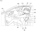
- FIG. 1 On the figure 1 , a seat 30 occupied by one person is shown.
- This seat 30 is installed here in the passenger compartment of a car. Alternatively, it could be installed in the passenger compartment of any other type of vehicle (truck, wagon, etc.).
- This seat conventionally comprises a seat 31 and a backrest 32 equipped with a headrest.
- the backrest 32 has a central support portion for the driver's back 20, and two sides located on either side of this central portion, placed on each side of the driver's trunk when the latter is seated in a centered position on the seat 30.
- the seat 30 is here equipped with a device 10 for restraining the driver 20 in the event of a side impact, that is to say a device for restraining the driver and absorbing the shock felt when the car hits an obstacle from the side or when it is itself hit from the side (left or right).
- the restraint device 10 comprises two airbags, hereinafter more simply called airbags 100.
- These two cushions 100 are located on either side of the driver 20. These two cushions 100 being similar (more precisely symmetrical to each other with respect to the median plane of the seat), only one of them will be described in the remainder of this presentation (namely the left cushion).
- this cushion 100 is equipped with a single gas generator cartridge 11 allowing it to be inflated in the event of an accident.
- the cushion 100 is more precisely housed in a pocket 12 located in one of the sides of the backrest 32, being folded into it.
- this cushion 100 will be described in the inflated and deployed state. It is also shown in the various figures in this state.
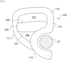
- the cushion 100 which is deployed on the left side of the driver 20, delimits two chambers 110, 120.
- Each of these two chambers 110, 120 is delimited by a fabric envelope 111, 121, which is distinct from that of the other chamber.
- the first envelope 111 which delimits the first of these chambers 110, here forms a curved sausage while the second envelope 121, which delimits the second chamber 120, forms a straight sausage.
- the first envelope 111 extends here from the left side of the backrest 32. It therefore has an end attached to this side, at the level of which there is an opening through which the gas from the cartridge is blown.
- This first envelope has, on the side of this end, a first part in the shape of an inverted S, which extends over a second part in order to form a loop 113.
- the first envelope 111 therefore forms a half-loop 112 (corresponding to the lower part of this S) which allows it to pass under the armpit of the arm 21, from the left side of the backrest, and to rise above the shoulder of the driver 20.
- This half-loop 112 then extends upwards and is curved forwards so as to form the loop 113.
- This loop 113 is complete (i.e. “closed”) since the second end of the first envelope 111 rests against the half-loop 112.
- the first envelope 111 therefore extends generally along a plane parallel to the median plane of the seat 30, on the side of the driver 20. Its loop 113 is placed in particular on the side of the head 22 of the driver 20. The upper part of this loop extends to the height of the top of the driver's head.
- the first envelope 111 has a width much less at the level of the half-loop 112 than at the level of the loop 113, so as not to force the driver to spread his arms.
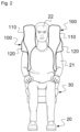
- the second envelope 121 which delimits the second chamber 120, extends generally along a diameter of the loop 113, at the height of the driver's neck. It has a maximum width greater than the maximum width of the first envelope 111 (see figure 2 ).
- This second envelope 121 is attached only by its front end to the first envelope 111. Its other end is free and it comes to rest against the first envelope 111.
- the two rooms 110, 120 are quite distinct but adapted to communicate with each other.
- the second envelope 121 is opened on the side of its front end and it is sewn on the edge of an opening provided in the first envelope 111.
- a membrane 125 is provided to isolate the two chambers 110, 120, which is adapted to yield when the pressure difference between the two chambers 110, 120 exceeds a threshold.
- This membrane 125 allows the first chamber 110 to inflate completely and to position itself correctly in the passenger compartment of the vehicle before the second chamber 120 inflates.
- the pressure threshold beyond which the membrane 125 will yield to allow the second chamber 120 to inflate will preferably be at least two times lower than the pressure necessary to cause the fabric envelopes 111, 121 to yield. It will even more preferably be lower than the maximum pressure which will be reached in the two chambers 110, 120 when the entire gas-emitting cartridge 11 has been consumed.
- this membrane 125 completely isolates the two chambers 110, 120, so that only the first chamber 110 inflates until the membrane 125 has given way under pressure.
- the membrane 125 only globally isolates the two chambers, tolerating leaks between the two chambers representing a maximum of 5 to 15% of the air volume.
- the membrane 125 allows the first chamber 110 to fully inflate to its deployed position in the vehicle before the second chamber 120 begins to deploy.
- membrane 125 can be envisaged, and in particular the following three.
- the membrane 125 is made of a material which is different from that used to make the envelopes 111, 121 and which is adapted to tear when the pressure difference between the two chambers 110, 120 exceeds the expected threshold.
- the membrane can then be glued or, preferably, sewn onto the envelopes, or even fixed to them in various other ways.
- the membrane 125 can be made of rubber.
- it can be made from a fabric whose yarn and weave have a known breaking strength at least twice as low as that of the fabric used to make the envelopes 111, 121.
- the membrane 125 is made of a material identical to that of the envelopes 111, 121. In this embodiment, the membrane 125 is then fixed to the envelopes 111, 121 by fixing means adapted to give way when the pressure difference between the two chambers 110, 120 exceeds the expected threshold.
- the membrane 125 can be sewn onto one or the other of the envelopes using a thread having a known breaking strength, which strength is at least two times lower than the strength of the thread used to sew the two envelopes 111, 121 onto each other.
- the membrane 125 may be bonded to either envelope using an adhesive having a known breaking strength.
- the membrane 125 is made of a material distinct from that of the envelopes 111, 121, which is adapted to tear when the pressure difference between the two chambers 110, 120 exceeds the expected threshold, and the membrane 125 is fixed to the envelopes 111, 121 by fixing means adapted to give way when the pressure difference between the two chambers 110, 120 exceeds this threshold.
- This third embodiment provides redundancy that ensures membrane rupture when the first chamber is fully inflated and deployed in the proper position.
- the space delimited internally by the loop 113 formed by the first envelope 111 is preferably entirely closed, on the one hand by the second envelope 121, and on the other hand by two sails 131, 132 which extend on either side of the second envelope 121. These two sails make it possible to ensure that the cushion 100 takes the desired shape when it is inflated.
- the two sails 131, 132 can each be formed from a single sheet of fabric or from strips separated from each other. They can be sewn onto the edges of the envelopes. They differ from these envelopes in that they are not inflatable. Here, they are formed from a single thickness of fabric. On the figure 1 , the sails have been hatched to distinguish them from the two envelopes and to allow the driver's head to appear transparently.
- the cushion 100 will be devoid of a strap allowing it to be held relative to the seat in order to ensure its deployment in the desired position. Only one end of the first envelope 111 is in fact attached to the seat.
- the seat could be equipped with only one cushion of the type shown in the figure 2 , in which case this cushion will preferably be placed between the driver and his door.
Landscapes
- Engineering & Computer Science (AREA)
- Mechanical Engineering (AREA)
- Air Bags (AREA)
Claims (10)
- Rückhaltevorrichtung (10) zum Zurückhalten eines Insassen (20) eines Sitzes (30) eines Fahrzeugs (40), umfassend mindestens ein aufblasbares Sicherheitskissen (100), das geeignet ist, in dem Sitz (30) aufgenommen zu werden, und das, wenn es sich aufbläst, geeignet ist, sich auf einer Seite des Insassen (20) zu entfalten, wobei dieses aufblasbare Sicherheitskissen (100) zwei verschiedene Kammern (110, 120) begrenzt, die geeignet sind, miteinander in Verbindung zu stehen,dadurch gekennzeichnet, dass das aufblasbare Sicherheitskissen (100) dazu ausgebildet ist, wenn es sich aufbläst, unter einer Achselhöhle des Insassen (20) zu verlaufen und auf der Seite des Kopfes (22) des Insassen (20) wieder aufzusteigen, unddadurch, dass eine Membran (125) vorgesehen ist, die die beiden Kammern (110, 120) trennt und die geeignet ist nachzugeben, wenn die Druckdifferenz zwischen den beiden Kammern (110, 120) einen Schwellenwert überschreitet.
- Rückhaltevorrichtung (10) nach dem vorhergehenden Anspruch, wobei die Membran (125) die beiden Kammern (110, 120) vollständig trennt.
- Rückhaltevorrichtung (10) nach einem der Ansprüche 1 und 2, wobei die erste Kammer (110) eine Schlaufe bildet.
- Rückhaltevorrichtung (10) nach Anspruch 3, wobei sich die zweite Kammer (120) im Wesentlichen entlang eines Durchmessers der Schlaufe erstreckt.
- Rückhaltevorrichtung (10) nach einem der Ansprüche 1 bis 4, wobei die Membran (125) aus einem Material ausgeführt ist, das verschieden von dem des Rests des aufblasbaren Sicherheitskissens (100) ist und das geeignet ist zu reißen, wenn die Druckdifferenz zwischen den beiden Kammern (110, 120) den Schwellenwert überschreitet.
- Rückhaltevorrichtung (10) nach einem der Ansprüche 1 bis 4, wobei die Membran (125) aus einem Material ausgeführt ist, das identisch mit dem des Rests des aufblasbaren Sicherheitskissens (100) ist, und wobei die Membran (125) an dem Rest des aufblasbaren Sicherheitskissens (100) mit Befestigungsmitteln befestigt ist, die geeignet sind nachzugeben, wenn die Druckdifferenz zwischen den beiden Kammern (110, 120) den Schwellenwert überschreitet.
- Rückhaltevorrichtung (10) nach Anspruch 6, wobei die Befestigungsmittel eine Naht umfassen, die geeignet ist nachzugeben, wenn die Druckdifferenz zwischen den beiden Kammern (110, 120) den Schwellenwert überschreitet.
- Rückhaltevorrichtung (10) nach Anspruch 6, wobei die Befestigungsmittel einen Klebstoff umfassen, der geeignet ist nachzugeben, wenn die Druckdifferenz zwischen den beiden Kammern (110, 120) den Schwellenwert überschreitet.
- Rückhaltevorrichtung (10) nach einem der Ansprüche 1 bis 8, wobei ein weiteres aufblasbares Sicherheitskissen (100) vorgesehen ist, das geeignet ist, sich auf der anderen Seite des Insassen (20) zu entfalten, wobei die beiden aufblasbaren Sicherheitskissen (100) im Wesentlichen symmetrisch zueinander sind.
- Sitz (30) für ein Fahrzeug, umfassend eine Sitzfläche (31) und eine Rückenlehne (32), dadurch gekennzeichnet, dass die Rückenlehne (32) eine Rückhaltevorrichtung (10) nach einem der Ansprüche 1 bis 9 umfasst.
Applications Claiming Priority (1)
| Application Number | Priority Date | Filing Date | Title |
|---|---|---|---|
| FR2107472A FR3124993B1 (fr) | 2021-07-09 | 2021-07-09 | Dispositif de sécurité comprenant au moins un airbag latéral |
Publications (2)
| Publication Number | Publication Date |
|---|---|
| EP4116154A1 EP4116154A1 (de) | 2023-01-11 |
| EP4116154B1 true EP4116154B1 (de) | 2024-12-11 |
Family
ID=77226941
Family Applications (1)
| Application Number | Title | Priority Date | Filing Date |
|---|---|---|---|
| EP22182430.3A Active EP4116154B1 (de) | 2021-07-09 | 2022-06-30 | Sicherheitsvorrichtung, die mindestens einen seitlichen airbag umfasst |
Country Status (2)
| Country | Link |
|---|---|
| EP (1) | EP4116154B1 (de) |
| FR (1) | FR3124993B1 (de) |
Family Cites Families (3)
| Publication number | Priority date | Publication date | Assignee | Title |
|---|---|---|---|---|
| JP3456754B2 (ja) * | 1994-06-14 | 2003-10-14 | 本田技研工業株式会社 | 車両用エアバッグの展開方法 |
| DE102009033181B3 (de) | 2009-07-13 | 2010-12-30 | Autoliv Development Ab | Fahrzeugsitz, Seitengassackeinrichtung und Sicherheitseinrichtung |
| FR2951678B1 (fr) * | 2009-10-27 | 2011-10-28 | Zodiac Automotive Division | Dispositif pour la protection des occupants d'un vehicule en cas de choc comprenant au moins un coussin gonflable |
-
2021
- 2021-07-09 FR FR2107472A patent/FR3124993B1/fr active Active
-
2022
- 2022-06-30 EP EP22182430.3A patent/EP4116154B1/de active Active
Also Published As
| Publication number | Publication date |
|---|---|
| FR3124993B1 (fr) | 2024-10-25 |
| EP4116154A1 (de) | 2023-01-11 |
| FR3124993A1 (fr) | 2023-01-13 |
Similar Documents
| Publication | Publication Date | Title |
|---|---|---|
| EP0529389B1 (de) | Sicherheitseinrichtung in Form eines Gaskissens für Kraftfahrzeug | |
| EP1193141B1 (de) | Kraftfahrzeugsitz mit einer Kopfstütze, die ein integriertes Gaskissen enthält | |
| FR2753665A1 (fr) | Systeme de coussin d'air pour choc lateral, notamment pour vehicule automobile | |
| FR2710015A1 (fr) | Dispositif servant à protéger un occupant d'un véhicule. | |
| FR2720352A1 (fr) | Système de retenue pour enfant. | |
| EP0819587B1 (de) | Luftsackmodul-Anordnung in einem Fahrzeugsitz | |
| FR2931421A1 (fr) | Dispositif de securite a sac gonflable pour un vehicule | |
| EP4116154B1 (de) | Sicherheitsvorrichtung, die mindestens einen seitlichen airbag umfasst | |
| FR3102961A1 (fr) | Module accoudoir pour dossier de banquette intégrant un coussin gonflable de sécurité | |
| FR2901756A1 (fr) | Garniture de siege de vehicule muni d'un coussin gonflable | |
| EP4008592B1 (de) | Vorrichtung zum zurückhalten eines insassen auf einem sitz eines kraftfahrzeugsitzes | |
| WO2025120030A1 (fr) | Module de sécurité conducteur pour protéger un conducteur d'un véhicule | |
| EP0818366B1 (de) | Luftsackmodul-Anordnung in einem Fahrzeugsitzteil | |
| EP2782795B1 (de) | Airbagvorrichtung mit einem deflektor und einem beutelstützenden flansch | |
| WO2024165155A1 (fr) | Dispositif de retenue d'un occupant d'un siege de vehicule | |
| FR3132256A1 (fr) | Dispositif de retenue d’un occupant d’un siège de véhicule | |
| EP3815988B1 (de) | Fahrzeugsitz, der mit einer thorax-schutzvorrichtung ausgestattet ist | |
| FR3128920A1 (fr) | Véhicule automobile comprenant un dispositif de coussin gonflable de sécurité. | |
| FR3166113A1 (fr) | Système de protection pour un passager avant d’un véhicule automobile | |
| FR3130718A1 (fr) | Dispositif de sécurité gonflable intégré dans la zone arrière de pavillon. | |
| FR3164956A1 (fr) | Siège de véhicule et procédé de montage d’un siège | |
| FR3155478A1 (fr) | Module de sécurité conducteur pour protéger un conducteur d’un véhicule | |
| FR3123855A1 (fr) | Véhicule automobile avec au moins trois rangées de sièges et comprenant des coussins de sécurité gonflables latéraux de type rideau | |
| FR3139065A1 (fr) | Sous-ensemble de planche de bord pour véhicule pourvu d’une cuvette de rangement associée à un coussin gonflable de sécurité. | |
| FR2904280A1 (fr) | Couvercle ab sur bielle |
Legal Events
| Date | Code | Title | Description |
|---|---|---|---|
| PUAI | Public reference made under article 153(3) epc to a published international application that has entered the european phase |
Free format text: ORIGINAL CODE: 0009012 |
|
| STAA | Information on the status of an ep patent application or granted ep patent |
Free format text: STATUS: THE APPLICATION HAS BEEN PUBLISHED |
|
| AK | Designated contracting states |
Kind code of ref document: A1 Designated state(s): AL AT BE BG CH CY CZ DE DK EE ES FI FR GB GR HR HU IE IS IT LI LT LU LV MC MK MT NL NO PL PT RO RS SE SI SK SM TR |
|
| STAA | Information on the status of an ep patent application or granted ep patent |
Free format text: STATUS: REQUEST FOR EXAMINATION WAS MADE |
|
| P01 | Opt-out of the competence of the unified patent court (upc) registered |
Effective date: 20230608 |
|
| 17P | Request for examination filed |
Effective date: 20230710 |
|
| RBV | Designated contracting states (corrected) |
Designated state(s): AL AT BE BG CH CY CZ DE DK EE ES FI FR GB GR HR HU IE IS IT LI LT LU LV MC MK MT NL NO PL PT RO RS SE SI SK SM TR |
|
| STAA | Information on the status of an ep patent application or granted ep patent |
Free format text: STATUS: EXAMINATION IS IN PROGRESS |
|
| 17Q | First examination report despatched |
Effective date: 20230901 |
|
| GRAP | Despatch of communication of intention to grant a patent |
Free format text: ORIGINAL CODE: EPIDOSNIGR1 |
|
| STAA | Information on the status of an ep patent application or granted ep patent |
Free format text: STATUS: GRANT OF PATENT IS INTENDED |
|
| INTG | Intention to grant announced |
Effective date: 20240702 |
|
| GRAS | Grant fee paid |
Free format text: ORIGINAL CODE: EPIDOSNIGR3 |
|
| GRAA | (expected) grant |
Free format text: ORIGINAL CODE: 0009210 |
|
| STAA | Information on the status of an ep patent application or granted ep patent |
Free format text: STATUS: THE PATENT HAS BEEN GRANTED |
|
| AK | Designated contracting states |
Kind code of ref document: B1 Designated state(s): AL AT BE BG CH CY CZ DE DK EE ES FI FR GB GR HR HU IE IS IT LI LT LU LV MC MK MT NL NO PL PT RO RS SE SI SK SM TR |
|
| REG | Reference to a national code |
Ref country code: GB Ref legal event code: FG4D Free format text: NOT ENGLISH |
|
| REG | Reference to a national code |
Ref country code: CH Ref legal event code: EP |
|
| REG | Reference to a national code |
Ref country code: DE Ref legal event code: R096 Ref document number: 602022008549 Country of ref document: DE |
|
| REG | Reference to a national code |
Ref country code: IE Ref legal event code: FG4D Free format text: LANGUAGE OF EP DOCUMENT: FRENCH |
|
| REG | Reference to a national code |
Ref country code: LT Ref legal event code: MG9D |
|
| PG25 | Lapsed in a contracting state [announced via postgrant information from national office to epo] |
Ref country code: HR Free format text: LAPSE BECAUSE OF FAILURE TO SUBMIT A TRANSLATION OF THE DESCRIPTION OR TO PAY THE FEE WITHIN THE PRESCRIBED TIME-LIMIT Effective date: 20241211 |
|
| PG25 | Lapsed in a contracting state [announced via postgrant information from national office to epo] |
Ref country code: FI Free format text: LAPSE BECAUSE OF FAILURE TO SUBMIT A TRANSLATION OF THE DESCRIPTION OR TO PAY THE FEE WITHIN THE PRESCRIBED TIME-LIMIT Effective date: 20241211 |
|
| PG25 | Lapsed in a contracting state [announced via postgrant information from national office to epo] |
Ref country code: BG Free format text: LAPSE BECAUSE OF FAILURE TO SUBMIT A TRANSLATION OF THE DESCRIPTION OR TO PAY THE FEE WITHIN THE PRESCRIBED TIME-LIMIT Effective date: 20241211 |
|
| REG | Reference to a national code |
Ref country code: NL Ref legal event code: MP Effective date: 20241211 |
|
| PG25 | Lapsed in a contracting state [announced via postgrant information from national office to epo] |
Ref country code: ES Free format text: LAPSE BECAUSE OF FAILURE TO SUBMIT A TRANSLATION OF THE DESCRIPTION OR TO PAY THE FEE WITHIN THE PRESCRIBED TIME-LIMIT Effective date: 20241211 |
|
| PG25 | Lapsed in a contracting state [announced via postgrant information from national office to epo] |
Ref country code: NO Free format text: LAPSE BECAUSE OF FAILURE TO SUBMIT A TRANSLATION OF THE DESCRIPTION OR TO PAY THE FEE WITHIN THE PRESCRIBED TIME-LIMIT Effective date: 20250311 |
|
| PG25 | Lapsed in a contracting state [announced via postgrant information from national office to epo] |
Ref country code: GR Free format text: LAPSE BECAUSE OF FAILURE TO SUBMIT A TRANSLATION OF THE DESCRIPTION OR TO PAY THE FEE WITHIN THE PRESCRIBED TIME-LIMIT Effective date: 20250312 Ref country code: LV Free format text: LAPSE BECAUSE OF FAILURE TO SUBMIT A TRANSLATION OF THE DESCRIPTION OR TO PAY THE FEE WITHIN THE PRESCRIBED TIME-LIMIT Effective date: 20241211 |
|
| PG25 | Lapsed in a contracting state [announced via postgrant information from national office to epo] |
Ref country code: RS Free format text: LAPSE BECAUSE OF FAILURE TO SUBMIT A TRANSLATION OF THE DESCRIPTION OR TO PAY THE FEE WITHIN THE PRESCRIBED TIME-LIMIT Effective date: 20250311 |
|
| PG25 | Lapsed in a contracting state [announced via postgrant information from national office to epo] |
Ref country code: NL Free format text: LAPSE BECAUSE OF FAILURE TO SUBMIT A TRANSLATION OF THE DESCRIPTION OR TO PAY THE FEE WITHIN THE PRESCRIBED TIME-LIMIT Effective date: 20241211 |
|
| REG | Reference to a national code |
Ref country code: AT Ref legal event code: MK05 Ref document number: 1750162 Country of ref document: AT Kind code of ref document: T Effective date: 20241211 |
|
| PG25 | Lapsed in a contracting state [announced via postgrant information from national office to epo] |
Ref country code: SM Free format text: LAPSE BECAUSE OF FAILURE TO SUBMIT A TRANSLATION OF THE DESCRIPTION OR TO PAY THE FEE WITHIN THE PRESCRIBED TIME-LIMIT Effective date: 20241211 |
|
| PG25 | Lapsed in a contracting state [announced via postgrant information from national office to epo] |
Ref country code: PL Free format text: LAPSE BECAUSE OF FAILURE TO SUBMIT A TRANSLATION OF THE DESCRIPTION OR TO PAY THE FEE WITHIN THE PRESCRIBED TIME-LIMIT Effective date: 20241211 |
|
| PGFP | Annual fee paid to national office [announced via postgrant information from national office to epo] |
Ref country code: DE Payment date: 20250618 Year of fee payment: 4 |
|
| PG25 | Lapsed in a contracting state [announced via postgrant information from national office to epo] |
Ref country code: IS Free format text: LAPSE BECAUSE OF FAILURE TO SUBMIT A TRANSLATION OF THE DESCRIPTION OR TO PAY THE FEE WITHIN THE PRESCRIBED TIME-LIMIT Effective date: 20250411 |
|
| PG25 | Lapsed in a contracting state [announced via postgrant information from national office to epo] |
Ref country code: PT Free format text: LAPSE BECAUSE OF FAILURE TO SUBMIT A TRANSLATION OF THE DESCRIPTION OR TO PAY THE FEE WITHIN THE PRESCRIBED TIME-LIMIT Effective date: 20250411 |
|
| PG25 | Lapsed in a contracting state [announced via postgrant information from national office to epo] |
Ref country code: EE Free format text: LAPSE BECAUSE OF FAILURE TO SUBMIT A TRANSLATION OF THE DESCRIPTION OR TO PAY THE FEE WITHIN THE PRESCRIBED TIME-LIMIT Effective date: 20241211 |
|
| PGFP | Annual fee paid to national office [announced via postgrant information from national office to epo] |
Ref country code: FR Payment date: 20250627 Year of fee payment: 4 |
|
| PG25 | Lapsed in a contracting state [announced via postgrant information from national office to epo] |
Ref country code: RO Free format text: LAPSE BECAUSE OF FAILURE TO SUBMIT A TRANSLATION OF THE DESCRIPTION OR TO PAY THE FEE WITHIN THE PRESCRIBED TIME-LIMIT Effective date: 20241211 Ref country code: AT Free format text: LAPSE BECAUSE OF FAILURE TO SUBMIT A TRANSLATION OF THE DESCRIPTION OR TO PAY THE FEE WITHIN THE PRESCRIBED TIME-LIMIT Effective date: 20241211 |
|
| PG25 | Lapsed in a contracting state [announced via postgrant information from national office to epo] |
Ref country code: SK Free format text: LAPSE BECAUSE OF FAILURE TO SUBMIT A TRANSLATION OF THE DESCRIPTION OR TO PAY THE FEE WITHIN THE PRESCRIBED TIME-LIMIT Effective date: 20241211 |
|
| PG25 | Lapsed in a contracting state [announced via postgrant information from national office to epo] |
Ref country code: CZ Free format text: LAPSE BECAUSE OF FAILURE TO SUBMIT A TRANSLATION OF THE DESCRIPTION OR TO PAY THE FEE WITHIN THE PRESCRIBED TIME-LIMIT Effective date: 20241211 |
|
| PG25 | Lapsed in a contracting state [announced via postgrant information from national office to epo] |
Ref country code: IT Free format text: LAPSE BECAUSE OF FAILURE TO SUBMIT A TRANSLATION OF THE DESCRIPTION OR TO PAY THE FEE WITHIN THE PRESCRIBED TIME-LIMIT Effective date: 20241211 |
|
| PG25 | Lapsed in a contracting state [announced via postgrant information from national office to epo] |
Ref country code: SE Free format text: LAPSE BECAUSE OF FAILURE TO SUBMIT A TRANSLATION OF THE DESCRIPTION OR TO PAY THE FEE WITHIN THE PRESCRIBED TIME-LIMIT Effective date: 20241211 |
|
| REG | Reference to a national code |
Ref country code: DE Ref legal event code: R097 Ref document number: 602022008549 Country of ref document: DE |
|
| PG25 | Lapsed in a contracting state [announced via postgrant information from national office to epo] |
Ref country code: DK Free format text: LAPSE BECAUSE OF FAILURE TO SUBMIT A TRANSLATION OF THE DESCRIPTION OR TO PAY THE FEE WITHIN THE PRESCRIBED TIME-LIMIT Effective date: 20241211 |
|
| PLBE | No opposition filed within time limit |
Free format text: ORIGINAL CODE: 0009261 |
|
| STAA | Information on the status of an ep patent application or granted ep patent |
Free format text: STATUS: NO OPPOSITION FILED WITHIN TIME LIMIT |
|
| REG | Reference to a national code |
Ref country code: CH Ref legal event code: L10 Free format text: ST27 STATUS EVENT CODE: U-0-0-L10-L00 (AS PROVIDED BY THE NATIONAL OFFICE) Effective date: 20251022 |
|
| 26N | No opposition filed |
Effective date: 20250912 |
|
| REG | Reference to a national code |
Ref country code: CH Ref legal event code: H13 Free format text: ST27 STATUS EVENT CODE: U-0-0-H10-H13 (AS PROVIDED BY THE NATIONAL OFFICE) Effective date: 20260127 |
|
| PG25 | Lapsed in a contracting state [announced via postgrant information from national office to epo] |
Ref country code: MC Free format text: LAPSE BECAUSE OF FAILURE TO SUBMIT A TRANSLATION OF THE DESCRIPTION OR TO PAY THE FEE WITHIN THE PRESCRIBED TIME-LIMIT Effective date: 20241211 |
|
| PG25 | Lapsed in a contracting state [announced via postgrant information from national office to epo] |
Ref country code: LU Free format text: LAPSE BECAUSE OF NON-PAYMENT OF DUE FEES Effective date: 20250630 |
|
| REG | Reference to a national code |
Ref country code: BE Ref legal event code: MM Effective date: 20250630 |
|
| PG25 | Lapsed in a contracting state [announced via postgrant information from national office to epo] |
Ref country code: IE Free format text: LAPSE BECAUSE OF NON-PAYMENT OF DUE FEES Effective date: 20250630 |
|
| PG25 | Lapsed in a contracting state [announced via postgrant information from national office to epo] |
Ref country code: BE Free format text: LAPSE BECAUSE OF NON-PAYMENT OF DUE FEES Effective date: 20250630 |