EP4115928A1 - Syringe set, syringe, and set - Google Patents
Syringe set, syringe, and set Download PDFInfo
- Publication number
- EP4115928A1 EP4115928A1 EP21768244.2A EP21768244A EP4115928A1 EP 4115928 A1 EP4115928 A1 EP 4115928A1 EP 21768244 A EP21768244 A EP 21768244A EP 4115928 A1 EP4115928 A1 EP 4115928A1
- Authority
- EP
- European Patent Office
- Prior art keywords
- connection port
- syringe
- blocking member
- injection needle
- drug
- Prior art date
- Legal status (The legal status is an assumption and is not a legal conclusion. Google has not performed a legal analysis and makes no representation as to the accuracy of the status listed.)
- Granted
Links
Images






Classifications
-
- A—HUMAN NECESSITIES
- A61—MEDICAL OR VETERINARY SCIENCE; HYGIENE
- A61J—CONTAINERS SPECIALLY ADAPTED FOR MEDICAL OR PHARMACEUTICAL PURPOSES; DEVICES OR METHODS SPECIALLY ADAPTED FOR BRINGING PHARMACEUTICAL PRODUCTS INTO PARTICULAR PHYSICAL OR ADMINISTERING FORMS; DEVICES FOR ADMINISTERING FOOD OR MEDICINES ORALLY; BABY COMFORTERS; DEVICES FOR RECEIVING SPITTLE
- A61J1/00—Containers specially adapted for medical or pharmaceutical purposes
- A61J1/14—Details; Accessories therefor
- A61J1/20—Arrangements for transferring or mixing fluids, e.g. from vial to syringe
- A61J1/2096—Combination of a vial and a syringe for transferring or mixing their contents
-
- A—HUMAN NECESSITIES
- A61—MEDICAL OR VETERINARY SCIENCE; HYGIENE
- A61J—CONTAINERS SPECIALLY ADAPTED FOR MEDICAL OR PHARMACEUTICAL PURPOSES; DEVICES OR METHODS SPECIALLY ADAPTED FOR BRINGING PHARMACEUTICAL PRODUCTS INTO PARTICULAR PHYSICAL OR ADMINISTERING FORMS; DEVICES FOR ADMINISTERING FOOD OR MEDICINES ORALLY; BABY COMFORTERS; DEVICES FOR RECEIVING SPITTLE
- A61J1/00—Containers specially adapted for medical or pharmaceutical purposes
- A61J1/14—Details; Accessories therefor
- A61J1/20—Arrangements for transferring or mixing fluids, e.g. from vial to syringe
- A61J1/2003—Accessories used in combination with means for transfer or mixing of fluids, e.g. for activating fluid flow, separating fluids, filtering fluid or venting
- A61J1/2048—Connecting means
- A61J1/2055—Connecting means having gripping means
-
- A—HUMAN NECESSITIES
- A61—MEDICAL OR VETERINARY SCIENCE; HYGIENE
- A61M—DEVICES FOR INTRODUCING MEDIA INTO, OR ONTO, THE BODY; DEVICES FOR TRANSDUCING BODY MEDIA OR FOR TAKING MEDIA FROM THE BODY; DEVICES FOR PRODUCING OR ENDING SLEEP OR STUPOR
- A61M5/00—Devices for bringing media into the body in a subcutaneous, intra-vascular or intramuscular way; Accessories therefor, e.g. filling or cleaning devices, arm rests
- A61M5/002—Packages specially adapted therefor, e.g. packages for syringes or needles or kits for diabetics
-
- A—HUMAN NECESSITIES
- A61—MEDICAL OR VETERINARY SCIENCE; HYGIENE
- A61M—DEVICES FOR INTRODUCING MEDIA INTO, OR ONTO, THE BODY; DEVICES FOR TRANSDUCING BODY MEDIA OR FOR TAKING MEDIA FROM THE BODY; DEVICES FOR PRODUCING OR ENDING SLEEP OR STUPOR
- A61M5/00—Devices for bringing media into the body in a subcutaneous, intra-vascular or intramuscular way; Accessories therefor, e.g. filling or cleaning devices, arm rests
- A61M5/178—Syringes
- A61M5/1782—Devices aiding filling of syringes in situ
-
- A—HUMAN NECESSITIES
- A61—MEDICAL OR VETERINARY SCIENCE; HYGIENE
- A61M—DEVICES FOR INTRODUCING MEDIA INTO, OR ONTO, THE BODY; DEVICES FOR TRANSDUCING BODY MEDIA OR FOR TAKING MEDIA FROM THE BODY; DEVICES FOR PRODUCING OR ENDING SLEEP OR STUPOR
- A61M5/00—Devices for bringing media into the body in a subcutaneous, intra-vascular or intramuscular way; Accessories therefor, e.g. filling or cleaning devices, arm rests
- A61M5/178—Syringes
- A61M5/31—Details
- A61M5/3129—Syringe barrels
- A61M5/3134—Syringe barrels characterised by constructional features of the distal end, i.e. end closest to the tip of the needle cannula
-
- A—HUMAN NECESSITIES
- A61—MEDICAL OR VETERINARY SCIENCE; HYGIENE
- A61M—DEVICES FOR INTRODUCING MEDIA INTO, OR ONTO, THE BODY; DEVICES FOR TRANSDUCING BODY MEDIA OR FOR TAKING MEDIA FROM THE BODY; DEVICES FOR PRODUCING OR ENDING SLEEP OR STUPOR
- A61M5/00—Devices for bringing media into the body in a subcutaneous, intra-vascular or intramuscular way; Accessories therefor, e.g. filling or cleaning devices, arm rests
- A61M5/178—Syringes
- A61M5/31—Details
- A61M5/315—Pistons; Piston-rods; Guiding, blocking or restricting the movement of the rod or piston; Appliances on the rod for facilitating dosing ; Dosing mechanisms
- A61M5/31596—Pistons; Piston-rods; Guiding, blocking or restricting the movement of the rod or piston; Appliances on the rod for facilitating dosing ; Dosing mechanisms comprising means for injection of two or more media, e.g. by mixing
-
- A—HUMAN NECESSITIES
- A61—MEDICAL OR VETERINARY SCIENCE; HYGIENE
- A61M—DEVICES FOR INTRODUCING MEDIA INTO, OR ONTO, THE BODY; DEVICES FOR TRANSDUCING BODY MEDIA OR FOR TAKING MEDIA FROM THE BODY; DEVICES FOR PRODUCING OR ENDING SLEEP OR STUPOR
- A61M5/00—Devices for bringing media into the body in a subcutaneous, intra-vascular or intramuscular way; Accessories therefor, e.g. filling or cleaning devices, arm rests
- A61M5/178—Syringes
- A61M5/31—Details
- A61M5/32—Needles; Details of needles pertaining to their connection with syringe or hub; Accessories for bringing the needle into, or holding the needle on, the body; Devices for protection of needles
- A61M5/3202—Devices for protection of the needle before use, e.g. caps
-
- A—HUMAN NECESSITIES
- A61—MEDICAL OR VETERINARY SCIENCE; HYGIENE
- A61M—DEVICES FOR INTRODUCING MEDIA INTO, OR ONTO, THE BODY; DEVICES FOR TRANSDUCING BODY MEDIA OR FOR TAKING MEDIA FROM THE BODY; DEVICES FOR PRODUCING OR ENDING SLEEP OR STUPOR
- A61M5/00—Devices for bringing media into the body in a subcutaneous, intra-vascular or intramuscular way; Accessories therefor, e.g. filling or cleaning devices, arm rests
- A61M5/178—Syringes
- A61M5/31—Details
- A61M5/32—Needles; Details of needles pertaining to their connection with syringe or hub; Accessories for bringing the needle into, or holding the needle on, the body; Devices for protection of needles
- A61M5/34—Constructions for connecting the needle, e.g. to syringe nozzle or needle hub
- A61M5/344—Constructions for connecting the needle, e.g. to syringe nozzle or needle hub using additional parts, e.g. clamping rings or collets
-
- A—HUMAN NECESSITIES
- A61—MEDICAL OR VETERINARY SCIENCE; HYGIENE
- A61M—DEVICES FOR INTRODUCING MEDIA INTO, OR ONTO, THE BODY; DEVICES FOR TRANSDUCING BODY MEDIA OR FOR TAKING MEDIA FROM THE BODY; DEVICES FOR PRODUCING OR ENDING SLEEP OR STUPOR
- A61M5/00—Devices for bringing media into the body in a subcutaneous, intra-vascular or intramuscular way; Accessories therefor, e.g. filling or cleaning devices, arm rests
- A61M5/178—Syringes
- A61M5/31—Details
- A61M5/32—Needles; Details of needles pertaining to their connection with syringe or hub; Accessories for bringing the needle into, or holding the needle on, the body; Devices for protection of needles
- A61M5/34—Constructions for connecting the needle, e.g. to syringe nozzle or needle hub
- A61M5/344—Constructions for connecting the needle, e.g. to syringe nozzle or needle hub using additional parts, e.g. clamping rings or collets
- A61M5/345—Adaptors positioned between needle hub and syringe nozzle
-
- A—HUMAN NECESSITIES
- A61—MEDICAL OR VETERINARY SCIENCE; HYGIENE
- A61J—CONTAINERS SPECIALLY ADAPTED FOR MEDICAL OR PHARMACEUTICAL PURPOSES; DEVICES OR METHODS SPECIALLY ADAPTED FOR BRINGING PHARMACEUTICAL PRODUCTS INTO PARTICULAR PHYSICAL OR ADMINISTERING FORMS; DEVICES FOR ADMINISTERING FOOD OR MEDICINES ORALLY; BABY COMFORTERS; DEVICES FOR RECEIVING SPITTLE
- A61J1/00—Containers specially adapted for medical or pharmaceutical purposes
- A61J1/14—Details; Accessories therefor
- A61J1/20—Arrangements for transferring or mixing fluids, e.g. from vial to syringe
- A61J1/2003—Accessories used in combination with means for transfer or mixing of fluids, e.g. for activating fluid flow, separating fluids, filtering fluid or venting
- A61J1/2006—Piercing means
- A61J1/201—Piercing means having one piercing end
-
- A—HUMAN NECESSITIES
- A61—MEDICAL OR VETERINARY SCIENCE; HYGIENE
- A61M—DEVICES FOR INTRODUCING MEDIA INTO, OR ONTO, THE BODY; DEVICES FOR TRANSDUCING BODY MEDIA OR FOR TAKING MEDIA FROM THE BODY; DEVICES FOR PRODUCING OR ENDING SLEEP OR STUPOR
- A61M2205/00—General characteristics of the apparatus
- A61M2205/27—General characteristics of the apparatus preventing use
- A61M2205/276—General characteristics of the apparatus preventing use preventing unwanted use
-
- A—HUMAN NECESSITIES
- A61—MEDICAL OR VETERINARY SCIENCE; HYGIENE
- A61M—DEVICES FOR INTRODUCING MEDIA INTO, OR ONTO, THE BODY; DEVICES FOR TRANSDUCING BODY MEDIA OR FOR TAKING MEDIA FROM THE BODY; DEVICES FOR PRODUCING OR ENDING SLEEP OR STUPOR
- A61M2207/00—Methods of manufacture, assembly or production
Definitions
- the present invention relates to a syringe set, a syringe, and a set to be used for an injection to be prepared by mixing drugs before use.
- An injection to be used after two drugs that are separately stored are mixed is used.
- Such an injection is provided, for example, in such a manner that one drug is enclosed in a vial container or a syringe as a powder and the other drug is enclosed in a syringe for injection as a solution such as water for injection or physiological saline ( JP 2013-132349 A ).
- the injection is prepared by connecting one syringe (or vial) to the other syringe for injection and mixing the two drugs while operating a plunger of the syringe for injection. Then, the prepared injection is transferred to the syringe for injection, the syringe (or vial) is removed, and an injection needle is attached to the syringe for injection to perform administration.
- a syringe set including: a first syringe including a barrel that stores a liquid first drug and a first connection port that is provided at a distal end of the barrel and communicates with inside of the barrel; and a drug container that stores a second drug and includes a second connection port that is detachable from the first connection port, the first connection port including an injection needle attachment structure to which an injection needle is attachable, and a blocking member that is disposed in the injection needle attachment structure and blocks attachment of the injection needle to the injection needle attachment structure, when the second connection port is connected to the first connection port, the blocking member being connected to the second connection port side, and when the second connection port to which the blocking member is connected is detached from the first connection port, the blocking member being detached from the first connection port so as to allow the injection needle to be attached to the injection needle attachment structure.
- a syringe that is connected to a drug container that stores a second drug immediately before use and is used for administration after a liquid first drug inside the syringe is mixed with the second drug
- the syringe including: a barrel that stores the first drug; and a first connection port that is provided at a distal end of the barrel and configured to be connectable to the drug container, the first connection port including an injection needle attachment structure to which an injection needle is attachable, and a blocking member that is disposed in the injection needle attachment structure and blocks attachment of the injection needle to the injection needle attachment structure, when the drug container is connected to the first connection port, the blocking member being connected to the drug container side, and when the drug container to which the blocking member is connected is detached from the first connection port, the blocking member being detached from the first connection port so as to allow the injection needle to be attached to the injection needle attachment structure.
- a set including: a drug container that stores a second drug; and a syringe that is connected to the drug container immediately before use and is used for administration after a liquid first drug inside the syringe is mixed with the second drug, the syringe including a barrel that stores the first drug, and a first connection port that is provided at a distal end of the barrel and is configured to be connectable to the drug container, the first connection port including an injection needle attachment structure to which an injection needle is attachable, and a blocking member that is disposed in the injection needle attachment structure and blocks attachment of the injection needle to the injection needle attachment structure, when the drug container is connected to the first connection port, the blocking member being connected to the drug container side, and when the drug container to which the blocking member is connected is detached from the first connection port, the blocking member being detached from the first connection port so as to allow the injection needle to be attached to the injection needle attachment structure.
- the injection needle is not attached if mixing is forgotten, so that it is possible to prevent erroneous administration due to forgetting of mixing.
- a syringe set 10 is used for an injection to be prepared by mixing two types of drugs that are separately stored and includes a first syringe 12 (syringe), a second syringe 14, and an injection needle 16 as illustrated in Fig. 1 .
- the first syringe 12 and the second syringe 14 store different types of drugs, respectively.
- the first syringe 12, the second syringe 14, and the injection needle 16 are provided to a user in a state where they are accommodated in a tray 20 having a plurality of accommodation recesses 20a to 20d.
- a second plunger 18 of the second syringe 14 is separated from the second syringe 14 and accommodated in the accommodation recess 20d.
- the second plunger 18 may be assembled to the second syringe 14 in advance.
- the first syringe 12 includes a first barrel 22, a first plunger 24, and a first cap 26.
- the first barrel 22 is formed in a cylindrical shape, a first opening portion 28 is formed on a proximal end side, and a first connection port 30 is formed on a distal end side.
- a first storage chamber 32 Inside of the first barrel 22 is a first storage chamber 32 that stores a drug.
- the first barrel 22 is formed with a transparent resin so as to allow a state of the first drug A inside the first barrel 22 to be visually recognized.
- a first gasket 34 is inserted into the first barrel 22, and a proximal end side of the first storage chamber 32 is sealed by the first gasket 34.
- the first drug A is sealed in the first storage chamber 32.
- the first drug A can be, for example, a liquid such as water (injection water) or physiological saline for diluting the other second drug B.
- the first plunger 24 is inserted from the first opening portion 28 on the proximal end side of the first barrel 22.
- the first plunger 24 is connected to the first gasket 34.
- the first plunger 24 may be configured to be attached to the first gasket 34 immediately before use.
- the first connection port 30 is a structure for connection to a second connection port 60 (see Fig. 3B ) of the second syringe 14 which will be described later and connection of the injection needle 16.
- the first connection port 30 includes a lock portion 36 extending in a tubular shape from the vicinity of an outer periphery of the first barrel 22 toward the distal end side of the first barrel 22, and a luer tip 38 extending in a tubular shape from the vicinity of a central axis of the first barrel 22 toward the distal end side of the first barrel 22 inside the lock portion 36.
- the injection needle attachment structure of the first connection port 30 includes the lock portion 36 and the luer tip 38. In the first connection port 30 in an unused state, a blocking member 40 that blocks attachment of the injection needle 16 is disposed between the lock portion 36 and the luer tip 38.
- a male screw 42 is formed on an outer peripheral portion 36a of the lock portion 36.
- the male screw 42 is constituted with one or more spiral screw structures.
- a needle connection screw 44 for screwing and attaching the injection needle 16 is formed on an inner peripheral portion 36b of the lock portion 36.
- the needle connection screw 44 is constituted as a spiral screw structure having the same pitch as the male screw 42.
- the luer tip 38 is formed to protrude longer toward the distal end side in an axial direction than the lock portion 36.
- a through hole 46 penetrating in the axial direction is formed in the vicinity of the central axis of the luer tip 38.
- a proximal end side of the through hole 46 is opened to the first storage chamber 32 of the first barrel 22, so that the through hole 46 communicates with the first storage chamber 32.
- An outer peripheral portion 38a of the luer tip 38 is formed in a tapered shape such that an outer diameter gradually decreases toward the distal end side.
- the outer peripheral portion 38a of the luer tip 38 is formed to have an outer diameter smaller than that of the inner peripheral portion 36b of the lock portion 36, and a gap 48 is formed between the outer peripheral portion 38a and the inner peripheral portion 36b of the lock portion 36.
- the blocking member 40 that blocks entry of a proximal end of the injection needle 16 is disposed in the gap 48.
- the blocking member 40 is formed in a cylindrical shape having an outer diameter and an inner diameter that allow the blocking member 40 to be inserted into the gap 48.
- a proximal end portion 40a of the blocking member 40 abuts on the distal end of the first barrel 22, and a distal end portion 40b of the blocking member 40 extends to the vicinity of the distal end of the lock portion 36.
- An outer peripheral portion 40c of the blocking member 40 is provided with a male screw 50 that can be screwed into the needle connection screw 44 of the inner peripheral portion 36b of the lock portion 36.
- the male screw 50 has a screw structure with the same pitch as the needle connection screw 44 and is screwed into the needle connection screw 44 to prevent the blocking member 40 from falling off to the distal end side.
- An inner peripheral portion 40d of the blocking member 40 is formed to have an inner diameter larger than that of the outer peripheral portion 38a of the luer tip 38, and the inner peripheral portion 40d is separated radially outward of the luer tip 38.
- a columnar gap 52 is formed between the inner peripheral portion 40d of the blocking member 40 and the outer peripheral portion 38a of the luer tip 38.
- a width (dimension) in a radial direction of the gap 52 is set to a value substantially equal to or slightly smaller than a thickness (dimension in a radial direction) of the inner tubular portion 78 of the second connection port 60 which will be described later.
- a first cap 26 is detachably attached to the distal end side of the first connection port 30.
- the first cap 26 includes a cylindrical main body portion 54 and a sealing member 56 disposed so as to close an inner peripheral side of the main body portion 54.
- the main body portion 54 includes a twisting portion 54a to be screwed into the male screw 42 of the outer peripheral portion 36a of the lock portion 36.
- a first cap body portion 54b whose diameter is reduced radially inward is formed on the distal end side of the twisting portion 54a.
- a seal storage hole 54c having an inner diameter smaller than the inner diameter of the lock portion 36 is formed inside the first cap body portion 54b, and an end portion of the sealing member 56 is stored in the seal storage hole 54c.
- the sealing member 56 is formed with an elastically deformable material such as a rubber material, and a distal end portion 56a of the sealing member 56 is stored in the seal storage hole 54c.
- a recess 56b engaged with a protrusion 54d protruding from the seal storage hole 54c is formed in the distal end portion 56a, and the sealing member 56 is stored in a state where the sealing member 56 is not displaced in the axial direction by the recess 56b being engaged with the protrusion 54d.
- a close contact portion 56c formed in a tubular shape is formed on the proximal end side of the sealing member 56.
- the close contact portion 56c is formed in a bottomed cylindrical shape that can be in close contact with the outer peripheral surface of the luer tip 38.
- Part of a distal end side of the close contact portion 56c is formed thick and is compressed in the radial direction by the outer peripheral surface of the luer tip 38 and the seal storage hole 54c, so that the close contact portion 56c is reliably brought into close contact with the outer peripheral surface of the luer tip 38.
- the sealing member 56 seals the through hole 46 at the distal end of the luer tip 38 in an airtight and liquid-tight manner.
- the distal end side of the first storage chamber 32 of the first barrel 22 is sealed by the sealing member 56.
- the second syringe 14 includes a second barrel 62, a second plunger 18, and a second cap 66.
- the second barrel 62 is formed in a cylindrical shape, a second opening portion 68 is formed on the proximal end side, and a second connection port 60 is formed on the distal end side.
- a second storage chamber 72 Inside of the second barrel 62 is a second storage chamber 72 that stores a drug.
- a second gasket 74 is inserted into the second barrel 62, and a proximal end side of the second storage chamber 72 is sealed by the second gasket 74.
- the second barrel 62 is formed with a transparent resin so as to allow a state of the second drug B inside the second barrel 62 to be visually recognized.
- the second drug B can be, for example, a powder or a liquid.
- the second plunger 18 can be inserted from the second opening portion 68 on the proximal end side of the second barrel 62, and the second plunger 18 is connected to the second gasket 74 immediately before use as illustrated in the drawing.
- the second plunger 18 may be attached to the second gasket 74 in advance.
- the second connection port 60 is used for connection to the first connection port 30 (see Fig. 2B ) of the first syringe 12.
- the second connection port 60 includes an outer tubular portion 76 extending in a tubular shape from the vicinity of an outer periphery of the second barrel 62 toward the distal end side of the second barrel 62, and an inner tubular portion 78 extending in a tubular shape from the vicinity of a central axis of the second barrel 62 toward the distal end side of the second barrel 62 inside the outer tubular portion 76.
- the outer tubular portion 76 is formed in a cylindrical shape having an inner diameter larger than that of the lock portion 36, and a female screw 80 is formed on an inner peripheral portion 76a of the outer tubular portion 76.
- the female screw 80 is formed with the same number of stripes and the same pitch as the male screw 42 formed on the outer peripheral portion 36a of the lock portion 36, and the female screw 80 can be screwed into the male screw 42.
- the inner tubular portion 78 is formed to be slightly shorter in the axial direction than the outer tubular portion 76.
- a communication hole 82 penetrating in the axial direction is formed on the inner peripheral side of the inner tubular portion 78.
- the proximal end side of the communication hole 82 is opened to a second storage chamber 72 of the second barrel 62, so that the communication hole 82 communicates with the second storage chamber 72.
- An inner peripheral portion 78b of the inner tubular portion 78 is formed in a tapered shape such that an inner diameter gradually decreases toward the proximal end side so as to be in close contact with the outer peripheral portion 38a of the luer tip 38.
- a thickness (dimension in a radial direction) of the inner tubular portion 78 is set to be equal to or slightly larger than the gap 52 between the inner peripheral portion 40d of the blocking member 40 and the outer peripheral portion 38a of the luer tip 38.
- a gap 83 is formed between the inner tubular portion 78 and the outer tubular portion 76. The lock portion 36 and the blocking member 40 of the first connection port 30 are inserted into the gap 83.
- the second cap 66 is detachably attached to the distal end side of the second connection port 60.
- the second cap 66 includes a cylindrical main body portion 84 and a seal member 86 disposed so as to close the inner peripheral side of the main body portion 84.
- the main body portion 84 includes a twisting portion 84a to be screwed into the female screw 80 of the inner peripheral portion 76a of the outer tubular portion 76.
- a second cap body portion 84b that holds the seal member 86 is formed on the distal end side of the twisting portion 84a.
- a protrusion 84c protruding inward is formed in the second cap body portion 84b, and the seal member 86 is held by the second cap body portion 84b by the seal member 86 being caught by the protrusion 84c.
- the seal member 86 is formed with an elastically deformable material such as a rubber material, and a distal end portion 86b of the seal member 86 is stored in the second cap body portion 84b.
- a columnar portion 86a is formed on the proximal end side of the seal member 86, and the columnar portion 86a is inserted into the communication hole 82 of the inner tubular portion 78 to seal the communication hole 82 in an airtight and liquid-tight manner.
- the distal end side of the second storage chamber 72 of the second barrel 62 is sealed by the seal member 86.
- the injection needle 16 includes a needle tube 16a and a needle hub 16b that supports the needle tube 16a.
- the needle tube 16a is formed with a metal such as stainless steel, for example, and a needle tip 16c capable of puncturing the skin is formed at the distal end of the needle tube 16a.
- the needle hub 16b is formed with, for example, a resin member, and a needle hole communicating with the inside of the needle tube 16a is provided inside the needle hub 16b.
- the needle hole inside the needle hub 16b is formed in a shape that can be brought into close contact with the luer tip 38 of the first connection port 30.
- a flange portion 16d that can be screwed into the needle connection screw 44 of the lock portion 36 is provided at the proximal end of the needle hub 16b.
- the injection needle 16 is provided in a state where the needle tube 16a is covered with the needle cap 16e.
- the syringe set 10 of the present embodiment is configured as described above, and action thereof will be described below.
- the first syringe 12 and the second syringe 14 of the syringe set 10 are removed from the tray 20 of Fig. 1 by a user. Thereafter, as illustrated in Fig. 4A , the user holds the first syringe 12 and rotates the first cap 26 to detach the first cap 26 from the first connection port 30.
- the lock portion 36 When the first cap 26 is removed from the first connection port 30, the lock portion 36 appears. In this state, the blocking member 40 is disposed on the inner peripheral side of the lock portion 36. As illustrated in Fig. 5 , when the user forgets mixing the first drug A and the second drug B and tries to attach the injection needle 16 to the first connection port 30 of the first syringe 12, the proximal end of the needle hub 16b of the injection needle 16 is hindered by the blocking member 40. In order to connect the injection needle 16 to the first connection port 30, it is necessary to screw the flange portion 16d of the injection needle 16 to the needle connection screw 44 of the lock portion 36.
- the injection needle 16 is blocked from proceeding by the blocking member 40, and thus the injection needle 16 is blocked from being screwed into the lock portion 36. This results in preventing the user from attaching the injection needle 16 to the first syringe 12 that stores only the first drug A.
- the user holds the second syringe 14 and rotates the second cap 66 to detach the second cap 66 from the second connection port 60.
- the first syringe 12 can be connected to the second syringe 14.
- the user screws the second connection port 60 of the second syringe 14 into the first connection port 30 of the first syringe 12 to connect the first connection port 30 to the second connection port 60.
- the female screw 80 of the inner peripheral portion 76a of the outer tubular portion 76 of the second connection port 60 and the male screw 42 of the outer peripheral portion 36a of the lock portion 36 of the first connection port 30 are screwed together, whereby the first connection port 30 is connected to the second connection port 60.
- the luer tip 38 of the first connection port 30 is connected in close contact with inside of the communication hole 82 of the inner tubular portion 78 of the second connection port 60 in a liquid-tight and airtight manner.
- the first storage chamber 32 of the first syringe 12 communicates with the second storage chamber 72 of the second syringe 14.
- the inner tubular portion 78 of the second connection port 60 is inserted into the gap 52 between the blocking member 40 and the luer tip 38, and the blocking member 40 is fitted and joined to the inner tubular portion 78.
- the user performs operation of alternately pushing the first plunger 24 (see Fig. 2A ) of the first syringe 12 and the second plunger 18 (see Fig. 3A ) of the second syringe 14.
- the first drug A in the first storage chamber 32 and the second drug B in the second storage chamber 72 are mixed, and preparation of an injection C is completed.
- the user rotates the second syringe 14 to detach the second syringe 14 from the first syringe 12.
- the blocking member 40 rotates integrally with the inner tubular portion 78 of the second connection port 60.
- the pitch of the male screw 50 of the blocking member 40 is the same as the pitch of the female screw 80 of the outer tubular portion 76 of the second connection port 60, and thus the blocking member 40 is also detached from the needle connection screw 44 of the inner peripheral portion 36b of the lock portion 36 along with release of screwing of the second connection port 60 to the first connection port 30.
- the injection needle 16 can be connected to the first connection port 30.
- the injection needle 16 is screwed into the first connection port 30 of the first syringe 12 to connect the injection needle 16, whereby preparation for administration of the injection C is completed. Thereafter, the user removes the needle cap 16e of the injection needle 16, punctures the needle tip 16c subcutaneously, and presses the first plunger 24 (see Fig. 2A ) to administer the injection C. Thus, administration of the injection C using the syringe set 10 is completed.
- the syringe set 10 of the present embodiment has the following effects.
- the syringe set 10 of the present embodiment includes the first syringe 12 and the second syringe 14 (drug container).
- the first syringe 12 includes the first barrel 22 that stores a liquid first drug A, and the first connection port 30 that is provided at the distal end of the first barrel 22 and communicates with inside of the first barrel 22.
- the second syringe 14 stores the second drug B and has the second connection port 60 detachable from the first connection port 30.
- the first connection port 30 includes the injection needle attachment structure to which the injection needle 16 is attached, and the blocking member 40 provided in the injection needle attachment structure to block attachment of the injection needle 16 to the injection needle attachment structure.
- the blocking member 40 When the second connection port 60 is connected to the first connection port 30, the blocking member 40 is connected to the second connection port 60 side, and when the second connection port 60 to which the blocking member 40 is connected is detached from the first connection port 30, the blocking member 40 is detached from the first connection port 30 so as to allow the injection needle 16 to be attached to the injection needle attachment structure.
- the injection needle 16 cannot be attached to the first syringe 12 unless the second connection port 60 is connected to the first connection port 30 and the first drug A of the first syringe 14 and the second drug B of the second syringe 12 are mixed. This can prevent the user from erroneously administering the unprepared first drug A as a result of attaching the injection needle 16 to the first syringe 12 that stores only the first drug A before the drugs are mixed.
- the injection needle attachment structure may include the tubular lock portion 36 in which the needle connection screw 44 into which the injection needle 16 is screwed is formed in the inner peripheral portion 36b, and the luer tip 38 formed inside the lock portion 36 and having the through hole 46 communicating with the inside of the first barrel 22, and the blocking member 40 may be disposed between the lock portion 36 and the luer tip 38. According to this configuration, it is possible to prevent the injection needle 16 from being screwed into the lock portion 36 by the blocking member 40.
- the blocking member 40 is formed in a cylindrical shape, and the outer peripheral portion 40c is provided with the male screw 50 as a protrusion to be screwed into the needle connection screw 44 on the inner peripheral side of the lock portion 36. As described above, the blocking member 40 is screwed into the needle connection screw 44, so that it is possible to prevent falling off to the distal end side.
- the male screw 42 may be formed on the outer peripheral portion 36a of the lock portion 36 of the first connection port 30, and the second connection port 60 may have the outer tubular portion 76 having, on the inner peripheral portion 76a, the female screw 80 that can be screwed into the male screw 42 of the outer peripheral portion 36a of the lock portion 36, and the inner tubular portion 78 that is formed inside the outer tubular portion 76, has the communication hole 82 communicating with the second storage chamber 72, is inserted between the lock portion 36 and the luer tip 38, and stores the luer tip 38 in the communication hole 82.
- the attachment structure of the inner tubular portion 78 and the luer tip 38 is simplified.
- the blocking member 40 may be configured such that the inner peripheral portion 40d is separated from the luer tip 38, and the inner tubular portion 78 is inserted into the inner peripheral portion 40d of the blocking member 40 and joined to the blocking member 40. According to this configuration, when the second connection port 60 is connected to the first connection port 30, the blocking member 40 is fitted and joined to the inner tubular portion 78.
- the blocking member 40 may block the vicinity of the distal end of the needle connection screw 44 of the inner peripheral portion 36b of the lock portion 36. According to this configuration, the injection needle 16 is reliably prevented from being screwed into the lock portion 36.
- the first cap 26 that seals the first syringe 12 may be provided, and the first cap 26 may include the first cap body portion 54b having the twisting portion 54a to be screwed into the male screw 42 of the outer peripheral portion 36a of the lock portion 36, and the sealing member 56 that is supported by the first cap body portion 54b and abuts on the luer tip 38 to seal the through hole 46.
- the drug container may be the second syringe 14 having the second barrel 62 as the second storage chamber 72 that stores the second drug B.
- the first syringe 12 of the present embodiment is connected to the drug container that stores the second drug B immediately before use, and administration is performed after the liquid first drug A is mixed with the second drug B.
- the first syringe 12 includes the first barrel 22 that stores the first drug A, and the first connection port 30 provided at the distal end of the first barrel 22 and configured to be connectable to the drug container (second syringe 14).
- the first connection port 30 is provided with the injection needle attachment structure to which the injection needle 16 is attachable, and the blocking member 40 that is disposed in the injection needle attachment structure and blocks attachment of the injection needle 16 to the injection needle attachment structure.
- the blocking member 40 is connected to the second syringe 14 side, and when the second syringe 14 to which the blocking member 40 is connected is detached from the first connection port 30, the blocking member 40 is detached from the first connection port 30 so as to allow the injection needle 16 to be attached to the injection needle attachment structure.
- the first syringe 12 having the above configuration, attachment of the injection needle 16 in a state of only the unmixed first drug A can be blocked by the blocking member 40, so that erroneous administration can be prevented.
- the male screw 50 is provided on the outer peripheral portion 40c of the blocking member 40, and the male screw 50 of the blocking member 40 is screwed into the needle connection screw 44 of the lock portion 36.
- the present embodiment is not limited to this.
- an outer peripheral portion 40c of a blocking member 40A may be provided with a protrusion 50A that can be screwed into the needle connection screw 44 of the lock portion 36 instead of the male screw 50.
- the protrusions 50A are provided as protrusions scattered so as to occupy only part of the outer peripheral portion 40c of the blocking member 40 in a circumferential direction.
- a plurality of protrusions 50A may be provided at the same pitch as the pitch of the needle connection screw 44 in the axial direction, or only one protrusion may be provided in the axial direction.
- the blocking member 40A of the present modification the same effects as those of the blocking member 40 can be obtained.
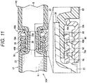
- a syringe set 10A of the present embodiment is different from the syringe set 10 described with reference to Figs. 1 to 9 in that protrusions that can be engaged with each other are provided on an inner peripheral portion 40d of a blocking member 40B and an outer peripheral portion 78a of an inner tubular portion 78A.
- the same components as those of the syringe set 10 of the first embodiment are denoted by the same reference numerals, and the detailed description thereof will be omitted.
- the blocking member 40B includes a first protrusion 88 protruding inward from the inner peripheral portion 40d.
- the first protrusion 88 is provided in the vicinity of a distal end portion 40b of the blocking member 40B and is formed in an annular shape along the circumferential direction of the inner peripheral portion 40d.
- second protrusions 90 are provided on the outer peripheral portion 78a of the inner tubular portion 78A.
- the second protrusions 90 are annular protrusions protruding outward from the outer peripheral portion 78a of the inner tubular portion 78A and are formed in an annular shape along the circumferential direction of the inner tubular portion 78A.
- a plurality of the second protrusions 90 is provided at intervals in the axial direction.
- the second protrusions 90 are formed at a protrusion height that can be engaged with the first protrusion 88 of the blocking member 40B.
- An inclined surface 90a for smooth insertion into the first protrusion 88 is formed on the distal end side of the second protrusion 90.
- a vertical surface 90b that stands vertically to the axial direction is provided so as to be hardly detached from the first protrusion 88.
- the second protrusions 90 do not have to be formed in an entire region in the circumferential direction, and only one second protrusion may be provided in the axial direction.
- the outer tubular portion 76A is molded separately from the second syringe 14A.
- the outer tubular portion 76A is assembled to the second syringe 14A by being fitted to a fitting structure 77 provided at the distal end of the second barrel 62 and in the vicinity of a root of the inner tubular portion 78A.
- the outer tubular portion 76A may be integrally molded with the second syringe 14A similarly to the outer tubular portion 76 ( Fig. 3B ) of the first embodiment.
- the syringe set 10A of the present embodiment is configured as described above, and action thereof will be described below.
- the blocking member 40B is pulled out together with the inner tubular portion 78A by the second protrusions 90 being engaged with the first protrusion 88 of the blocking member 40B. Accordingly, the blocking member 40B can be reliably removed together with the second connection port 60A.
- the syringe set 10A of the present embodiment has the following effects.
- protrusions (the first protrusion 88 and the second protrusions 90) that can be engaged with each other are formed on the inner peripheral portion 40d of the blocking member 40B and the outer peripheral portion 78a of the inner tubular portion 78A.
- the protrusions may be formed in an annular shape extending in the circumferential direction. Accordingly, the blocking member 40B can be more reliably removed together with the inner tubular portion 78A.
- An uneven structure of the present embodiment is not limited to the annular first protrusion 88 and the second protrusions 90 and may be configured by a combination of an annular groove and a protrusion.
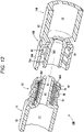
- a syringe set 10B of the present embodiment is provided with uneven structures that can be engaged with each other on an inner peripheral portion 40d of a blocking member 40C and an outer peripheral portion 78a of the inner tubular portion 78B.
- the uneven structure of the present embodiment is different from the syringe set 10A described with reference to Fig. 10 in including vertical ribs 92 extending in the axial direction formed in the inner peripheral portion 40d of the blocking member 40C.
- the same components as those of the syringe set 10A of the second embodiment are denoted by the same reference numerals, and the detailed description thereof will be omitted.
- the vertical ribs 92 extending in the axial direction are formed on the inner peripheral portion 40d of the blocking member 40C.
- a plurality of vertical ribs 92 is disposed at a constant pitch in the circumferential direction.
- an enlarged diameter portion 94 protruding radially outward is provided on a proximal end side of the inner tubular portion 78B in the outer peripheral portion 78a of the inner tubular portion 78B of the second syringe 14B.
- the syringe set 10B of the present embodiment is configured as described above, and action thereof will be described below.
- the inner tubular portion 78B is inserted into the inner peripheral portion 40d of the blocking member 40C.
- the inner tubular portion 78B and the blocking member 40C are joined by fitting.
- the blocking member 40C is detached together with the inner tubular portion 78B.
- the vertical ribs 92 of the blocking member 40C are caught by the inner tubular portion 78B to exert stronger joining force in a rotation direction, and thus, the blocking member 40C rotates integrally with the inner tubular portion 78B, so that the blocking member 40C can be removed more reliably.
- the syringe set 10B of the present embodiment includes the vertical ribs 92 extending in the axial direction as the uneven structure, so that the blocking member 40C can be reliably removed using the needle connection screw 44 of the lock portion 36.
- the vertical ribs 92 may be formed on the inner tubular portion 78B side. In addition, the vertical ribs 92 may be formed on both the inner peripheral portion 40d and the inner tubular portion 78B of the blocking member 40C.
- a syringe set 10C of the present embodiment is provided with uneven structures that can be engaged with each other on the inner peripheral portion 40d of a blocking member 40D and the outer peripheral portion 78a of an inner tubular portion 78C.
- Fig. 13 illustrates a cross section cut perpendicularly to the axial direction in a state where the second connection port 60C is connected to the first connection port 30.
- the uneven structure of the present embodiment is different from the syringe set 10A described with reference to Fig. 10 in including a ratchet structure 98 that rotates the blocking member 40D only in a predetermined direction.
- the same components as those of the syringe set 10A of the second embodiment are denoted by the same reference numerals, and the detailed description thereof will be omitted.
- first ratchet protrusions 99a extending in the axial direction are formed in an inner peripheral portion 40d.
- a plurality of first ratchet protrusions 99a are provided at regular intervals in the circumferential direction.
- An inclined surface is formed on one side of a side portion of the first ratchet protrusion 99a.
- second ratchet protrusions 99b are formed at a plurality of positions in the circumferential direction on the outer peripheral portion 78a of the inner tubular portion 78C of the second connection port 60C.
- One side portion of the second ratchet protrusion 99b is formed with an inclined surface.
- the first ratchet protrusions 99a and the second ratchet protrusions 99b come into contact with each other on their inclined surfaces and escape while being elastically deformed in a thickness direction. This enables the user to perform operation of screwing the second connection port 60C.
- the blocking member 40D rotates integrally with the inner tubular portion 78C and is displaced in a direction away from the first connection port 30 by the needle connection screw 44. As a result, the blocking member 40D is detached from the first connection port 30 together with the inner tubular portion 78C.
- the syringe set 10C of the present embodiment includes, as the uneven structure, the ratchet structure 98 that rotates the blocking member 40D only in a direction of separating from the needle connection screw 44 of the lock portion 36. Accordingly, the blocking member 40D can be reliably removed from the first connection port 30.
- a syringe set 10D (set) of the present embodiment includes the first syringe 12 and a vial adapter 100 (connector).
- the syringe set 10D is applied in a case where a vial (not illustrated) is used as a drug container instead of the second syringe 14.
- a vial not illustrated
- the same components as those of the syringe set 10 described with reference to Figs. 1 to 9 are denoted by the same reference numerals, and a detailed description thereof will be omitted.
- the vial adapter 100 is a member connected to a bottle opening of the vial container (not illustrated) and includes a connection portion 102 for connecting to the bottle opening of the vial container, a connection needle 104 penetrating a rubber stopper of the vial container, and a second connection port 60 for connecting to the first syringe 12.
- connection needle 104 is provided in the vicinity of a central axis of the connection portion 102 and protrudes to one end side of the connection portion 102.
- a cavity portion 104a is provided at the center of the connection needle 104.
- the cavity portion 104a communicates with an outer peripheral side of the connection needle 104 through a window portion 104b on a side portion.
- the cavity portion 104a communicates with inside of the vial container through the window portion 104b.
- the second connection port 60 extends from an opposite side of the connection needle 104 across the connection portion 102.
- a communication hole 82 of the second connection port 60 communicates with the cavity portion 104a of the connection needle 104.
- the syringe set 10D of the present embodiment is used by connecting the vial adapter 100 to a vial container and further connecting the first syringe 12 to the vial adapter 100.
- the second connection port 60 of the vial adapter 100 is connected to the first connection port 30 of the first syringe 12
- the blocking member 40 of the first connection port 30 is joined to the inner tubular portion 78 of the second connection port 60.
- the blocking member 40 is detached from the first connection port 30 together with the vial adapter 100.
- the injection needle 16 can be connected to the first syringe 12.
- the syringe set 10D of the present embodiment also prevents erroneous administration due to forgetting of mixing of an injection.
Landscapes
- Health & Medical Sciences (AREA)
- Veterinary Medicine (AREA)
- Life Sciences & Earth Sciences (AREA)
- Animal Behavior & Ethology (AREA)
- General Health & Medical Sciences (AREA)
- Public Health (AREA)
- Vascular Medicine (AREA)
- Engineering & Computer Science (AREA)
- Anesthesiology (AREA)
- Biomedical Technology (AREA)
- Heart & Thoracic Surgery (AREA)
- Hematology (AREA)
- Pharmacology & Pharmacy (AREA)
- Diabetes (AREA)
- Physics & Mathematics (AREA)
- Fluid Mechanics (AREA)
- Infusion, Injection, And Reservoir Apparatuses (AREA)
- Medical Preparation Storing Or Oral Administration Devices (AREA)
Abstract
Description
- The present invention relates to a syringe set, a syringe, and a set to be used for an injection to be prepared by mixing drugs before use.
- An injection to be used after two drugs that are separately stored are mixed is used. Such an injection is provided, for example, in such a manner that one drug is enclosed in a vial container or a syringe as a powder and the other drug is enclosed in a syringe for injection as a solution such as water for injection or physiological saline (
JP 2013-132349 A - The injection is prepared by connecting one syringe (or vial) to the other syringe for injection and mixing the two drugs while operating a plunger of the syringe for injection. Then, the prepared injection is transferred to the syringe for injection, the syringe (or vial) is removed, and an injection needle is attached to the syringe for injection to perform administration.
- By the way, work of preparing an injection is performed not only by a medical institution but also by a patient at home in some cases. When the patient himself/herself administers an injection, there is a case where the patient forgets mixing drugs. In such a case, there is a possibility that the patient erroneously recognizes a drug (for example, a solution such as an injection solution or physiological saline) enclosed in a syringe for injection as a prepared drug, attaches an injection needle to a syringe and erroneously administers the drug without performing mixing operation.
- It is therefore an object of one embodiment to provide a syringe set, a syringe, and a set capable of preventing erroneous administration of an injection that is to be prepared by mixing drugs before use, due to forgetting of mixing the drugs.
- According to one aspect of the following disclosure, there is provided a syringe set including: a first syringe including a barrel that stores a liquid first drug and a first connection port that is provided at a distal end of the barrel and communicates with inside of the barrel; and a drug container that stores a second drug and includes a second connection port that is detachable from the first connection port, the first connection port including an injection needle attachment structure to which an injection needle is attachable, and a blocking member that is disposed in the injection needle attachment structure and blocks attachment of the injection needle to the injection needle attachment structure, when the second connection port is connected to the first connection port, the blocking member being connected to the second connection port side, and when the second connection port to which the blocking member is connected is detached from the first connection port, the blocking member being detached from the first connection port so as to allow the injection needle to be attached to the injection needle attachment structure.
- According to another aspect, there is provided a syringe that is connected to a drug container that stores a second drug immediately before use and is used for administration after a liquid first drug inside the syringe is mixed with the second drug, the syringe including: a barrel that stores the first drug; and a first connection port that is provided at a distal end of the barrel and configured to be connectable to the drug container, the first connection port including an injection needle attachment structure to which an injection needle is attachable, and a blocking member that is disposed in the injection needle attachment structure and blocks attachment of the injection needle to the injection needle attachment structure, when the drug container is connected to the first connection port, the blocking member being connected to the drug container side, and when the drug container to which the blocking member is connected is detached from the first connection port, the blocking member being detached from the first connection port so as to allow the injection needle to be attached to the injection needle attachment structure.
- According to still another aspect, there is provided a set including: a drug container that stores a second drug; and a syringe that is connected to the drug container immediately before use and is used for administration after a liquid first drug inside the syringe is mixed with the second drug, the syringe including a barrel that stores the first drug, and a first connection port that is provided at a distal end of the barrel and is configured to be connectable to the drug container, the first connection port including an injection needle attachment structure to which an injection needle is attachable, and a blocking member that is disposed in the injection needle attachment structure and blocks attachment of the injection needle to the injection needle attachment structure, when the drug container is connected to the first connection port, the blocking member being connected to the drug container side, and when the drug container to which the blocking member is connected is detached from the first connection port, the blocking member being detached from the first connection port so as to allow the injection needle to be attached to the injection needle attachment structure.
- According to the syringe set, the syringe, and the set from the above viewpoints, the injection needle is not attached if mixing is forgotten, so that it is possible to prevent erroneous administration due to forgetting of mixing.
-
-
Fig. 1 is a plan view of a syringe set according to a first embodiment. -
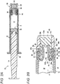
Fig. 2A is a cross-sectional view of a first syringe ofFig. 1 , andFig. 2B is an enlarged cross-sectional view of a distal end portion of the first syringe ofFig. 2A . -
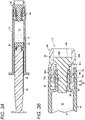
Fig. 3A is a cross-sectional view of a second syringe ofFig. 1 , andFig. 3B is an enlarged cross-sectional view of a distal end portion of the second syringe ofFig. 3A . -
Fig. 4A is a cross-sectional view of a state in which a cap of the first syringe is removed, andFig. 4B is a cross-sectional view of a state in which a cap of the second syringe is removed. -
Fig. 5 is a cross-sectional view illustrating action of a blocking member of a first connection port. -
Fig. 6 is a cross-sectional view illustrating a state in which a second connection port is connected to the first connection port and drugs are mixed between the first syringe and the second syringe. -
Fig. 7 is a cross-sectional view of a state in which the second connection port is removed from the first connection port after the drugs are mixed. -
Fig. 8 is a cross-sectional view of a state in which an injection needle is attached to the first connection port. -
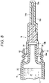
Fig. 9 is a side view of a blocking member according to a modification of the first embodiment. -
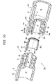
Fig. 10 is an exploded perspective cross-sectional view of a first syringe and a second syringe of a syringe set according to a second embodiment. -
Fig. 11 is a cross-sectional view of a state in which a second connection port is connected to a first connection port ofFig. 10 . -
Fig. 12 is a perspective cross-sectional view of a first syringe and a second syringe of a syringe set according to a third embodiment. -
Fig. 13 is a cross-sectional view of a state in which a first connection port is connected to a second connection port in a syringe set according to a fourth embodiment. -
Fig. 14 is a perspective view of a first syringe and a vial adapter of a syringe set according to a fifth embodiment. -
Fig. 15 is a cross-sectional view of a state in which the vial adapter is connected to the first syringe ofFig. 14 . - Hereinafter, the present invention will be described in detail using preferred embodiments of the present invention with reference to the accompanying drawings.
- A syringe set 10 according to the present embodiment is used for an injection to be prepared by mixing two types of drugs that are separately stored and includes a first syringe 12 (syringe), a
second syringe 14, and aninjection needle 16 as illustrated inFig. 1 . Thefirst syringe 12 and thesecond syringe 14 store different types of drugs, respectively. - The
first syringe 12, thesecond syringe 14, and theinjection needle 16 are provided to a user in a state where they are accommodated in atray 20 having a plurality of accommodation recesses 20a to 20d. Although not particularly limited, asecond plunger 18 of thesecond syringe 14 is separated from thesecond syringe 14 and accommodated in the accommodation recess 20d. Thesecond plunger 18 may be assembled to thesecond syringe 14 in advance. - As illustrated in
Fig. 2A , thefirst syringe 12 includes afirst barrel 22, afirst plunger 24, and afirst cap 26. Among them, thefirst barrel 22 is formed in a cylindrical shape, afirst opening portion 28 is formed on a proximal end side, and afirst connection port 30 is formed on a distal end side. Inside of thefirst barrel 22 is afirst storage chamber 32 that stores a drug. Thefirst barrel 22 is formed with a transparent resin so as to allow a state of the first drug A inside thefirst barrel 22 to be visually recognized. - A
first gasket 34 is inserted into thefirst barrel 22, and a proximal end side of thefirst storage chamber 32 is sealed by thefirst gasket 34. The first drug A is sealed in thefirst storage chamber 32. Although not particularly limited, the first drug A can be, for example, a liquid such as water (injection water) or physiological saline for diluting the other second drug B. - The
first plunger 24 is inserted from the first openingportion 28 on the proximal end side of thefirst barrel 22. Thefirst plunger 24 is connected to thefirst gasket 34. Thefirst plunger 24 may be configured to be attached to thefirst gasket 34 immediately before use. - The
first connection port 30 is a structure for connection to a second connection port 60 (seeFig. 3B ) of thesecond syringe 14 which will be described later and connection of theinjection needle 16. Thefirst connection port 30 includes alock portion 36 extending in a tubular shape from the vicinity of an outer periphery of thefirst barrel 22 toward the distal end side of thefirst barrel 22, and aluer tip 38 extending in a tubular shape from the vicinity of a central axis of thefirst barrel 22 toward the distal end side of thefirst barrel 22 inside thelock portion 36. The injection needle attachment structure of thefirst connection port 30 includes thelock portion 36 and theluer tip 38. In thefirst connection port 30 in an unused state, a blockingmember 40 that blocks attachment of theinjection needle 16 is disposed between thelock portion 36 and theluer tip 38. - A
male screw 42 is formed on an outerperipheral portion 36a of thelock portion 36. Themale screw 42 is constituted with one or more spiral screw structures. Further, aneedle connection screw 44 for screwing and attaching theinjection needle 16 is formed on an innerperipheral portion 36b of thelock portion 36. Theneedle connection screw 44 is constituted as a spiral screw structure having the same pitch as themale screw 42. - The
luer tip 38 is formed to protrude longer toward the distal end side in an axial direction than thelock portion 36. A throughhole 46 penetrating in the axial direction is formed in the vicinity of the central axis of theluer tip 38. A proximal end side of the throughhole 46 is opened to thefirst storage chamber 32 of thefirst barrel 22, so that the throughhole 46 communicates with thefirst storage chamber 32. An outerperipheral portion 38a of theluer tip 38 is formed in a tapered shape such that an outer diameter gradually decreases toward the distal end side. The outerperipheral portion 38a of theluer tip 38 is formed to have an outer diameter smaller than that of the innerperipheral portion 36b of thelock portion 36, and agap 48 is formed between the outerperipheral portion 38a and the innerperipheral portion 36b of thelock portion 36. The blockingmember 40 that blocks entry of a proximal end of theinjection needle 16 is disposed in thegap 48. - The blocking
member 40 is formed in a cylindrical shape having an outer diameter and an inner diameter that allow the blockingmember 40 to be inserted into thegap 48. Aproximal end portion 40a of the blockingmember 40 abuts on the distal end of thefirst barrel 22, and adistal end portion 40b of the blockingmember 40 extends to the vicinity of the distal end of thelock portion 36. An outer peripheral portion 40c of the blockingmember 40 is provided with amale screw 50 that can be screwed into theneedle connection screw 44 of the innerperipheral portion 36b of thelock portion 36. Themale screw 50 has a screw structure with the same pitch as theneedle connection screw 44 and is screwed into theneedle connection screw 44 to prevent the blockingmember 40 from falling off to the distal end side. - An inner
peripheral portion 40d of the blockingmember 40 is formed to have an inner diameter larger than that of the outerperipheral portion 38a of theluer tip 38, and the innerperipheral portion 40d is separated radially outward of theluer tip 38. Acolumnar gap 52 is formed between the innerperipheral portion 40d of the blockingmember 40 and the outerperipheral portion 38a of theluer tip 38. A width (dimension) in a radial direction of thegap 52 is set to a value substantially equal to or slightly smaller than a thickness (dimension in a radial direction) of the innertubular portion 78 of thesecond connection port 60 which will be described later. - A
first cap 26 is detachably attached to the distal end side of thefirst connection port 30. Thefirst cap 26 includes a cylindricalmain body portion 54 and a sealingmember 56 disposed so as to close an inner peripheral side of themain body portion 54. Themain body portion 54 includes a twistingportion 54a to be screwed into themale screw 42 of the outerperipheral portion 36a of thelock portion 36. A firstcap body portion 54b whose diameter is reduced radially inward is formed on the distal end side of the twistingportion 54a. Aseal storage hole 54c having an inner diameter smaller than the inner diameter of thelock portion 36 is formed inside the firstcap body portion 54b, and an end portion of the sealingmember 56 is stored in theseal storage hole 54c. - The sealing
member 56 is formed with an elastically deformable material such as a rubber material, and adistal end portion 56a of the sealingmember 56 is stored in theseal storage hole 54c. Arecess 56b engaged with aprotrusion 54d protruding from theseal storage hole 54c is formed in thedistal end portion 56a, and the sealingmember 56 is stored in a state where the sealingmember 56 is not displaced in the axial direction by therecess 56b being engaged with theprotrusion 54d. - A close contact portion 56c formed in a tubular shape is formed on the proximal end side of the sealing
member 56. The close contact portion 56c is formed in a bottomed cylindrical shape that can be in close contact with the outer peripheral surface of theluer tip 38. Part of a distal end side of the close contact portion 56c is formed thick and is compressed in the radial direction by the outer peripheral surface of theluer tip 38 and theseal storage hole 54c, so that the close contact portion 56c is reliably brought into close contact with the outer peripheral surface of theluer tip 38. The sealingmember 56 seals the throughhole 46 at the distal end of theluer tip 38 in an airtight and liquid-tight manner. The distal end side of thefirst storage chamber 32 of thefirst barrel 22 is sealed by the sealingmember 56. - On the other hand, as illustrated in
Fig. 3A , thesecond syringe 14 includes asecond barrel 62, asecond plunger 18, and asecond cap 66. Among them, thesecond barrel 62 is formed in a cylindrical shape, asecond opening portion 68 is formed on the proximal end side, and asecond connection port 60 is formed on the distal end side. Inside of thesecond barrel 62 is asecond storage chamber 72 that stores a drug. Asecond gasket 74 is inserted into thesecond barrel 62, and a proximal end side of thesecond storage chamber 72 is sealed by thesecond gasket 74. Thesecond barrel 62 is formed with a transparent resin so as to allow a state of the second drug B inside thesecond barrel 62 to be visually recognized. Although not particularly limited, the second drug B can be, for example, a powder or a liquid. - The
second plunger 18 can be inserted from thesecond opening portion 68 on the proximal end side of thesecond barrel 62, and thesecond plunger 18 is connected to thesecond gasket 74 immediately before use as illustrated in the drawing. Thesecond plunger 18 may be attached to thesecond gasket 74 in advance. - The
second connection port 60 is used for connection to the first connection port 30 (seeFig. 2B ) of thefirst syringe 12. Thesecond connection port 60 includes an outertubular portion 76 extending in a tubular shape from the vicinity of an outer periphery of thesecond barrel 62 toward the distal end side of thesecond barrel 62, and an innertubular portion 78 extending in a tubular shape from the vicinity of a central axis of thesecond barrel 62 toward the distal end side of thesecond barrel 62 inside the outertubular portion 76. - The outer
tubular portion 76 is formed in a cylindrical shape having an inner diameter larger than that of thelock portion 36, and afemale screw 80 is formed on an innerperipheral portion 76a of the outertubular portion 76. Thefemale screw 80 is formed with the same number of stripes and the same pitch as themale screw 42 formed on the outerperipheral portion 36a of thelock portion 36, and thefemale screw 80 can be screwed into themale screw 42. - The inner
tubular portion 78 is formed to be slightly shorter in the axial direction than the outertubular portion 76. Acommunication hole 82 penetrating in the axial direction is formed on the inner peripheral side of the innertubular portion 78. The proximal end side of thecommunication hole 82 is opened to asecond storage chamber 72 of thesecond barrel 62, so that thecommunication hole 82 communicates with thesecond storage chamber 72. An innerperipheral portion 78b of the innertubular portion 78 is formed in a tapered shape such that an inner diameter gradually decreases toward the proximal end side so as to be in close contact with the outerperipheral portion 38a of theluer tip 38. A thickness (dimension in a radial direction) of the innertubular portion 78 is set to be equal to or slightly larger than thegap 52 between the innerperipheral portion 40d of the blockingmember 40 and the outerperipheral portion 38a of theluer tip 38. Agap 83 is formed between the innertubular portion 78 and the outertubular portion 76. Thelock portion 36 and the blockingmember 40 of thefirst connection port 30 are inserted into thegap 83. - The
second cap 66 is detachably attached to the distal end side of thesecond connection port 60. Thesecond cap 66 includes a cylindricalmain body portion 84 and aseal member 86 disposed so as to close the inner peripheral side of themain body portion 84. Themain body portion 84 includes a twistingportion 84a to be screwed into thefemale screw 80 of the innerperipheral portion 76a of the outertubular portion 76. A secondcap body portion 84b that holds theseal member 86 is formed on the distal end side of the twistingportion 84a. Aprotrusion 84c protruding inward is formed in the secondcap body portion 84b, and theseal member 86 is held by the secondcap body portion 84b by theseal member 86 being caught by theprotrusion 84c. - The
seal member 86 is formed with an elastically deformable material such as a rubber material, and adistal end portion 86b of theseal member 86 is stored in the secondcap body portion 84b. Acolumnar portion 86a is formed on the proximal end side of theseal member 86, and thecolumnar portion 86a is inserted into thecommunication hole 82 of the innertubular portion 78 to seal thecommunication hole 82 in an airtight and liquid-tight manner. The distal end side of thesecond storage chamber 72 of thesecond barrel 62 is sealed by theseal member 86. - The
injection needle 16 includes aneedle tube 16a and aneedle hub 16b that supports theneedle tube 16a. Theneedle tube 16a is formed with a metal such as stainless steel, for example, and aneedle tip 16c capable of puncturing the skin is formed at the distal end of theneedle tube 16a. Theneedle hub 16b is formed with, for example, a resin member, and a needle hole communicating with the inside of theneedle tube 16a is provided inside theneedle hub 16b. The needle hole inside theneedle hub 16b is formed in a shape that can be brought into close contact with theluer tip 38 of thefirst connection port 30. In addition, aflange portion 16d that can be screwed into theneedle connection screw 44 of thelock portion 36 is provided at the proximal end of theneedle hub 16b. Theinjection needle 16 is provided in a state where theneedle tube 16a is covered with theneedle cap 16e. - The syringe set 10 of the present embodiment is configured as described above, and action thereof will be described below.
- The
first syringe 12 and thesecond syringe 14 of the syringe set 10 are removed from thetray 20 ofFig. 1 by a user. Thereafter, as illustrated inFig. 4A , the user holds thefirst syringe 12 and rotates thefirst cap 26 to detach thefirst cap 26 from thefirst connection port 30. - When the
first cap 26 is removed from thefirst connection port 30, thelock portion 36 appears. In this state, the blockingmember 40 is disposed on the inner peripheral side of thelock portion 36. As illustrated inFig. 5 , when the user forgets mixing the first drug A and the second drug B and tries to attach theinjection needle 16 to thefirst connection port 30 of thefirst syringe 12, the proximal end of theneedle hub 16b of theinjection needle 16 is hindered by the blockingmember 40. In order to connect theinjection needle 16 to thefirst connection port 30, it is necessary to screw theflange portion 16d of theinjection needle 16 to theneedle connection screw 44 of thelock portion 36. In thefirst syringe 12 of the present embodiment, theinjection needle 16 is blocked from proceeding by the blockingmember 40, and thus theinjection needle 16 is blocked from being screwed into thelock portion 36. This results in preventing the user from attaching theinjection needle 16 to thefirst syringe 12 that stores only the first drug A. - Thereafter, as illustrated in
Fig. 4B , the user holds thesecond syringe 14 and rotates thesecond cap 66 to detach thesecond cap 66 from thesecond connection port 60. As a result, thefirst syringe 12 can be connected to thesecond syringe 14. - Next, as illustrated in
Fig. 6 , the user screws thesecond connection port 60 of thesecond syringe 14 into thefirst connection port 30 of thefirst syringe 12 to connect thefirst connection port 30 to thesecond connection port 60. Thefemale screw 80 of the innerperipheral portion 76a of the outertubular portion 76 of thesecond connection port 60 and themale screw 42 of the outerperipheral portion 36a of thelock portion 36 of thefirst connection port 30 are screwed together, whereby thefirst connection port 30 is connected to thesecond connection port 60. - In addition, the
luer tip 38 of thefirst connection port 30 is connected in close contact with inside of thecommunication hole 82 of the innertubular portion 78 of thesecond connection port 60 in a liquid-tight and airtight manner. As a result, thefirst storage chamber 32 of thefirst syringe 12 communicates with thesecond storage chamber 72 of thesecond syringe 14. The innertubular portion 78 of thesecond connection port 60 is inserted into thegap 52 between the blockingmember 40 and theluer tip 38, and the blockingmember 40 is fitted and joined to the innertubular portion 78. - Thereafter, the user performs operation of alternately pushing the first plunger 24 (see
Fig. 2A ) of thefirst syringe 12 and the second plunger 18 (seeFig. 3A ) of thesecond syringe 14. As a result, the first drug A in thefirst storage chamber 32 and the second drug B in thesecond storage chamber 72 are mixed, and preparation of an injection C is completed. - Next, as illustrated in
Fig. 7 , after the prepared injection C is stored on thefirst syringe 12 side, the user rotates thesecond syringe 14 to detach thesecond syringe 14 from thefirst syringe 12. In this event, the blockingmember 40 rotates integrally with the innertubular portion 78 of thesecond connection port 60. The pitch of themale screw 50 of the blockingmember 40 is the same as the pitch of thefemale screw 80 of the outertubular portion 76 of thesecond connection port 60, and thus the blockingmember 40 is also detached from theneedle connection screw 44 of the innerperipheral portion 36b of thelock portion 36 along with release of screwing of thesecond connection port 60 to thefirst connection port 30. As a result, theinjection needle 16 can be connected to thefirst connection port 30. - Next, as illustrated in
Fig. 8 , theinjection needle 16 is screwed into thefirst connection port 30 of thefirst syringe 12 to connect theinjection needle 16, whereby preparation for administration of the injection C is completed. Thereafter, the user removes theneedle cap 16e of theinjection needle 16, punctures theneedle tip 16c subcutaneously, and presses the first plunger 24 (seeFig. 2A ) to administer the injection C. Thus, administration of the injection C using the syringe set 10 is completed. - The syringe set 10 of the present embodiment has the following effects.
- The syringe set 10 of the present embodiment includes the
first syringe 12 and the second syringe 14 (drug container). Thefirst syringe 12 includes thefirst barrel 22 that stores a liquid first drug A, and thefirst connection port 30 that is provided at the distal end of thefirst barrel 22 and communicates with inside of thefirst barrel 22. In addition, thesecond syringe 14 stores the second drug B and has thesecond connection port 60 detachable from thefirst connection port 30. Thefirst connection port 30 includes the injection needle attachment structure to which theinjection needle 16 is attached, and the blockingmember 40 provided in the injection needle attachment structure to block attachment of theinjection needle 16 to the injection needle attachment structure. When thesecond connection port 60 is connected to thefirst connection port 30, the blockingmember 40 is connected to thesecond connection port 60 side, and when thesecond connection port 60 to which the blockingmember 40 is connected is detached from thefirst connection port 30, the blockingmember 40 is detached from thefirst connection port 30 so as to allow theinjection needle 16 to be attached to the injection needle attachment structure. - According to the above configuration, the
injection needle 16 cannot be attached to thefirst syringe 12 unless thesecond connection port 60 is connected to thefirst connection port 30 and the first drug A of thefirst syringe 14 and the second drug B of thesecond syringe 12 are mixed. This can prevent the user from erroneously administering the unprepared first drug A as a result of attaching theinjection needle 16 to thefirst syringe 12 that stores only the first drug A before the drugs are mixed. - In the syringe set 10, the injection needle attachment structure may include the
tubular lock portion 36 in which theneedle connection screw 44 into which theinjection needle 16 is screwed is formed in the innerperipheral portion 36b, and theluer tip 38 formed inside thelock portion 36 and having the throughhole 46 communicating with the inside of thefirst barrel 22, and the blockingmember 40 may be disposed between thelock portion 36 and theluer tip 38. According to this configuration, it is possible to prevent theinjection needle 16 from being screwed into thelock portion 36 by the blockingmember 40. - In the syringe set 10, the blocking
member 40 is formed in a cylindrical shape, and the outer peripheral portion 40c is provided with themale screw 50 as a protrusion to be screwed into theneedle connection screw 44 on the inner peripheral side of thelock portion 36. As described above, the blockingmember 40 is screwed into theneedle connection screw 44, so that it is possible to prevent falling off to the distal end side. - In the syringe set 10 described above, the
male screw 42 may be formed on the outerperipheral portion 36a of thelock portion 36 of thefirst connection port 30, and thesecond connection port 60 may have the outertubular portion 76 having, on the innerperipheral portion 76a, thefemale screw 80 that can be screwed into themale screw 42 of the outerperipheral portion 36a of thelock portion 36, and the innertubular portion 78 that is formed inside the outertubular portion 76, has thecommunication hole 82 communicating with thesecond storage chamber 72, is inserted between thelock portion 36 and theluer tip 38, and stores theluer tip 38 in thecommunication hole 82. As a result, the attachment structure of the innertubular portion 78 and theluer tip 38 is simplified. - In the syringe set 10, the blocking
member 40 may be configured such that the innerperipheral portion 40d is separated from theluer tip 38, and the innertubular portion 78 is inserted into the innerperipheral portion 40d of the blockingmember 40 and joined to the blockingmember 40. According to this configuration, when thesecond connection port 60 is connected to thefirst connection port 30, the blockingmember 40 is fitted and joined to the innertubular portion 78. - In the syringe set 10 described above, the blocking
member 40 may block the vicinity of the distal end of theneedle connection screw 44 of the innerperipheral portion 36b of thelock portion 36. According to this configuration, theinjection needle 16 is reliably prevented from being screwed into thelock portion 36. - In the syringe set 10 described above, the
first cap 26 that seals thefirst syringe 12 may be provided, and thefirst cap 26 may include the firstcap body portion 54b having the twistingportion 54a to be screwed into themale screw 42 of the outerperipheral portion 36a of thelock portion 36, and the sealingmember 56 that is supported by the firstcap body portion 54b and abuts on theluer tip 38 to seal the throughhole 46. - In the syringe set 10, the drug container may be the
second syringe 14 having thesecond barrel 62 as thesecond storage chamber 72 that stores the second drug B. - In addition, the
first syringe 12 of the present embodiment is connected to the drug container that stores the second drug B immediately before use, and administration is performed after the liquid first drug A is mixed with the second drug B. Thefirst syringe 12 includes thefirst barrel 22 that stores the first drug A, and thefirst connection port 30 provided at the distal end of thefirst barrel 22 and configured to be connectable to the drug container (second syringe 14). Thefirst connection port 30 is provided with the injection needle attachment structure to which theinjection needle 16 is attachable, and the blockingmember 40 that is disposed in the injection needle attachment structure and blocks attachment of theinjection needle 16 to the injection needle attachment structure. Then, when thesecond syringe 14 is connected to thefirst connection port 30, the blockingmember 40 is connected to thesecond syringe 14 side, and when thesecond syringe 14 to which the blockingmember 40 is connected is detached from thefirst connection port 30, the blockingmember 40 is detached from thefirst connection port 30 so as to allow theinjection needle 16 to be attached to the injection needle attachment structure. - According to the
first syringe 12 having the above configuration, attachment of theinjection needle 16 in a state of only the unmixed first drug A can be blocked by the blockingmember 40, so that erroneous administration can be prevented. - In the example described with reference to
Fig. 2B , themale screw 50 is provided on the outer peripheral portion 40c of the blockingmember 40, and themale screw 50 of the blockingmember 40 is screwed into theneedle connection screw 44 of thelock portion 36. However, the present embodiment is not limited to this. - In other words, as illustrated in a separated state in
Fig. 9 , an outer peripheral portion 40c of a blockingmember 40A may be provided with aprotrusion 50A that can be screwed into theneedle connection screw 44 of thelock portion 36 instead of themale screw 50. Theprotrusions 50A are provided as protrusions scattered so as to occupy only part of the outer peripheral portion 40c of the blockingmember 40 in a circumferential direction. As illustrated in the drawing, a plurality ofprotrusions 50A may be provided at the same pitch as the pitch of theneedle connection screw 44 in the axial direction, or only one protrusion may be provided in the axial direction. - Also by the blocking
member 40A of the present modification, the same effects as those of the blockingmember 40 can be obtained. - As illustrated in
Fig. 10 , a syringe set 10A of the present embodiment is different from the syringe set 10 described with reference toFigs. 1 to 9 in that protrusions that can be engaged with each other are provided on an innerperipheral portion 40d of a blockingmember 40B and an outerperipheral portion 78a of an innertubular portion 78A. In the configuration of the syringe set 10A of the present embodiment, the same components as those of the syringe set 10 of the first embodiment are denoted by the same reference numerals, and the detailed description thereof will be omitted. - As illustrated in
Fig. 10 , the blockingmember 40B includes afirst protrusion 88 protruding inward from the innerperipheral portion 40d. Thefirst protrusion 88 is provided in the vicinity of adistal end portion 40b of the blockingmember 40B and is formed in an annular shape along the circumferential direction of the innerperipheral portion 40d. - In a
second connection port 60A of asecond syringe 14A,second protrusions 90 are provided on the outerperipheral portion 78a of the innertubular portion 78A. Thesecond protrusions 90 are annular protrusions protruding outward from the outerperipheral portion 78a of the innertubular portion 78A and are formed in an annular shape along the circumferential direction of the innertubular portion 78A. A plurality of thesecond protrusions 90 is provided at intervals in the axial direction. Thesecond protrusions 90 are formed at a protrusion height that can be engaged with thefirst protrusion 88 of the blockingmember 40B. Aninclined surface 90a for smooth insertion into thefirst protrusion 88 is formed on the distal end side of thesecond protrusion 90. In addition, on the proximal end side of thesecond protrusion 90, avertical surface 90b that stands vertically to the axial direction is provided so as to be hardly detached from thefirst protrusion 88. Thesecond protrusions 90 do not have to be formed in an entire region in the circumferential direction, and only one second protrusion may be provided in the axial direction. - Although not particularly limited, in the
second connection port 60A of the present embodiment, the outertubular portion 76A is molded separately from thesecond syringe 14A. The outertubular portion 76A is assembled to thesecond syringe 14A by being fitted to afitting structure 77 provided at the distal end of thesecond barrel 62 and in the vicinity of a root of the innertubular portion 78A. The outertubular portion 76A may be integrally molded with thesecond syringe 14A similarly to the outer tubular portion 76 (Fig. 3B ) of the first embodiment. - The syringe set 10A of the present embodiment is configured as described above, and action thereof will be described below.
- As illustrated in
Fig. 11 , when thesecond connection port 60A is connected to thefirst connection port 30, the innertubular portion 78A and thesecond protrusions 90 of the innertubular portion 78A are inserted into the proximal end side of thefirst protrusion 88 of the blockingmember 40B. When thesecond connection port 60A is removed from thefirst connection port 30, the blockingmember 40B is pulled out together with the innertubular portion 78A by thesecond protrusions 90 being engaged with thefirst protrusion 88 of the blockingmember 40B. Accordingly, the blockingmember 40B can be reliably removed together with thesecond connection port 60A. - The syringe set 10A of the present embodiment has the following effects.
- In the syringe set 10A of the present embodiment, protrusions (the
first protrusion 88 and the second protrusions 90) that can be engaged with each other are formed on the innerperipheral portion 40d of the blockingmember 40B and the outerperipheral portion 78a of the innertubular portion 78A. - This causes the inner
tubular portion 78A to be engaged with the blockingmember 40B, so that the blockingmember 40B can be more reliably removed. - In the syringe set 10A, the protrusions (the
first protrusion 88 and the second protrusions 90) may be formed in an annular shape extending in the circumferential direction. Accordingly, the blockingmember 40B can be more reliably removed together with the innertubular portion 78A. - An uneven structure of the present embodiment is not limited to the annular
first protrusion 88 and thesecond protrusions 90 and may be configured by a combination of an annular groove and a protrusion. - As illustrated in
Fig. 12 , a syringe set 10B of the present embodiment is provided with uneven structures that can be engaged with each other on an innerperipheral portion 40d of a blockingmember 40C and an outerperipheral portion 78a of the innertubular portion 78B. The uneven structure of the present embodiment is different from the syringe set 10A described with reference toFig. 10 in includingvertical ribs 92 extending in the axial direction formed in the innerperipheral portion 40d of the blockingmember 40C. In the configuration of the syringe set 10B of the present embodiment, the same components as those of the syringe set 10A of the second embodiment are denoted by the same reference numerals, and the detailed description thereof will be omitted. - As illustrated in
Fig. 12 , thevertical ribs 92 extending in the axial direction are formed on the innerperipheral portion 40d of the blockingmember 40C. A plurality ofvertical ribs 92 is disposed at a constant pitch in the circumferential direction. On the other hand, anenlarged diameter portion 94 protruding radially outward is provided on a proximal end side of the innertubular portion 78B in the outerperipheral portion 78a of the innertubular portion 78B of thesecond syringe 14B. - The syringe set 10B of the present embodiment is configured as described above, and action thereof will be described below.
- In the syringe set 10B, when the
second connection port 60B is connected to thefirst connection port 30, the innertubular portion 78B is inserted into the innerperipheral portion 40d of the blockingmember 40C. When theenlarged diameter portion 94 of the innertubular portion 78B is pushed into the innerperipheral portion 40d of the blockingmember 40C, the innertubular portion 78B and the blockingmember 40C are joined by fitting. - Thereafter, when the
second connection port 60B is rotated and removed from thefirst connection port 30, the blockingmember 40C is detached together with the innertubular portion 78B. In this event, thevertical ribs 92 of the blockingmember 40C are caught by the innertubular portion 78B to exert stronger joining force in a rotation direction, and thus, the blockingmember 40C rotates integrally with the innertubular portion 78B, so that the blockingmember 40C can be removed more reliably. - As described above, the syringe set 10B of the present embodiment includes the
vertical ribs 92 extending in the axial direction as the uneven structure, so that the blockingmember 40C can be reliably removed using theneedle connection screw 44 of thelock portion 36. - The
vertical ribs 92 may be formed on the innertubular portion 78B side. In addition, thevertical ribs 92 may be formed on both the innerperipheral portion 40d and the innertubular portion 78B of the blockingmember 40C. - As illustrated in
Fig. 13 , a syringe set 10C of the present embodiment is provided with uneven structures that can be engaged with each other on the innerperipheral portion 40d of a blockingmember 40D and the outerperipheral portion 78a of an inner tubular portion 78C.Fig. 13 illustrates a cross section cut perpendicularly to the axial direction in a state where the second connection port 60C is connected to thefirst connection port 30. The uneven structure of the present embodiment is different from the syringe set 10A described with reference toFig. 10 in including aratchet structure 98 that rotates the blockingmember 40D only in a predetermined direction. In the configuration of the syringe set 10C of the present embodiment, the same components as those of the syringe set 10A of the second embodiment are denoted by the same reference numerals, and the detailed description thereof will be omitted. - As illustrated in
Fig. 13 , in the blockingmember 40D of the present embodiment,first ratchet protrusions 99a extending in the axial direction are formed in an innerperipheral portion 40d. A plurality offirst ratchet protrusions 99a are provided at regular intervals in the circumferential direction. An inclined surface is formed on one side of a side portion of thefirst ratchet protrusion 99a. - On the other hand,
second ratchet protrusions 99b are formed at a plurality of positions in the circumferential direction on the outerperipheral portion 78a of the inner tubular portion 78C of the second connection port 60C. One side portion of thesecond ratchet protrusion 99b is formed with an inclined surface. - When the second connection port 60C is screwed into the
first connection port 30, thefirst ratchet protrusions 99a and thesecond ratchet protrusions 99b come into contact with each other on their inclined surfaces and escape while being elastically deformed in a thickness direction. This enables the user to perform operation of screwing the second connection port 60C. - On the other hand, when the second connection port 60C is rotated in a removal direction, the
first ratchet protrusions 99a and thesecond ratchet protrusions 99b are engaged with each other. As a result, the blockingmember 40D rotates integrally with the inner tubular portion 78C and is displaced in a direction away from thefirst connection port 30 by theneedle connection screw 44. As a result, the blockingmember 40D is detached from thefirst connection port 30 together with the inner tubular portion 78C. - As described above, the syringe set 10C of the present embodiment includes, as the uneven structure, the
ratchet structure 98 that rotates the blockingmember 40D only in a direction of separating from theneedle connection screw 44 of thelock portion 36. Accordingly, the blockingmember 40D can be reliably removed from thefirst connection port 30. - As illustrated in
Fig. 14 , a syringe set 10D (set) of the present embodiment includes thefirst syringe 12 and a vial adapter 100 (connector). The syringe set 10D is applied in a case where a vial (not illustrated) is used as a drug container instead of thesecond syringe 14. In the configuration of the syringe set 10D of the present embodiment, the same components as those of the syringe set 10 described with reference toFigs. 1 to 9 are denoted by the same reference numerals, and a detailed description thereof will be omitted. - As illustrated in the drawing, the
vial adapter 100 is a member connected to a bottle opening of the vial container (not illustrated) and includes aconnection portion 102 for connecting to the bottle opening of the vial container, aconnection needle 104 penetrating a rubber stopper of the vial container, and asecond connection port 60 for connecting to thefirst syringe 12. - As illustrated in
Fig. 15 , theconnection needle 104 is provided in the vicinity of a central axis of theconnection portion 102 and protrudes to one end side of theconnection portion 102. Acavity portion 104a is provided at the center of theconnection needle 104. Thecavity portion 104a communicates with an outer peripheral side of theconnection needle 104 through awindow portion 104b on a side portion. When the vial container is punctured with theconnection needle 104, thecavity portion 104a communicates with inside of the vial container through thewindow portion 104b. - The
second connection port 60 extends from an opposite side of theconnection needle 104 across theconnection portion 102. Acommunication hole 82 of thesecond connection port 60 communicates with thecavity portion 104a of theconnection needle 104. - The syringe set 10D of the present embodiment is used by connecting the
vial adapter 100 to a vial container and further connecting thefirst syringe 12 to thevial adapter 100. When thesecond connection port 60 of thevial adapter 100 is connected to thefirst connection port 30 of thefirst syringe 12, the blockingmember 40 of thefirst connection port 30 is joined to the innertubular portion 78 of thesecond connection port 60. - Then, when the
vial adapter 100 is removed from thefirst syringe 12 after preparation of the injection, the blockingmember 40 is detached from thefirst connection port 30 together with thevial adapter 100. As a result, theinjection needle 16 can be connected to thefirst syringe 12. - As described above, the syringe set 10D of the present embodiment also prevents erroneous administration due to forgetting of mixing of an injection.
- Although the present invention has been described above with reference to the preferred embodiments, the present invention is not limited to the above-described embodiments, and it goes without saying that various modifications can be made without departing from the gist of the present invention.
Claims (15)
- A syringe set comprising:a first syringe including a barrel that stores a liquid first drug, and a first connection port that is provided at a distal end of the barrel and communicates with inside of the barrel; anda drug container that stores a second drug and includes a second connection port that is detachable from the first connection port,the first connection port including an injection needle attachment structure to which an injection needle is attachable, and a blocking member that is disposed in the injection needle attachment structure and blocks attachment of the injection needle to the injection needle attachment structure,when the second connection port is connected to the first connection port, the blocking member being connected to the second connection port side, andwhen the second connection port to which the blocking member is connected is detached from the first connection port, the blocking member being detached from the first connection port so as to allow the injection needle to be attached to the injection needle attachment structure.
- The syringe set according to claim 1, wherein the injection needle attachment structure comprises: a tubular lock portion in which a needle connection screw into which the injection needle is to be screwed is formed on an inner peripheral portion; and a luer tip formed inside the lock portion and having a through hole communicating with the inside of the barrel, and
the blocking member is disposed between the lock portion and the luer tip. - The syringe set according to claim 2, wherein the blocking member is formed in a cylindrical shape, and a protrusion to be screwed into the needle connection screw of the inner peripheral portion of the lock portion is provided on an outer peripheral portion.
- The syringe set according to claim 2 or 3, whereina male screw is formed on an outer peripheral portion of the lock portion of the first connection port, andthe second connection port comprises:an outer tubular portion having a female screw on an inner periphery, the female screw being capable of being screwed into the male screw on the outer periphery portion of the lock portion; andan inner tubular portion that is formed inside the outer tubular portion, has a communication hole communicating with inside of the drug container, is inserted between the lock portion and the luer tip, and stores the luer tip in the communication hole.
- The syringe set according to claim 4, wherein an inner peripheral side of the blocking member is separated from the luer tip, and the inner tubular portion is inserted into the inner peripheral side of the blocking member and joined to the blocking member.
- The syringe set according to claim 5, wherein uneven structures engageable with each other are formed on an inner peripheral portion of the blocking member and an outer peripheral surface of the inner tubular portion.
- The syringe set according to claim 6, wherein the uneven structures include an annular protrusion extending in a circumferential direction.
- The syringe set according to claim 6, wherein the uneven structures include a vertical rib extending in an axial direction.
- The syringe set according to claim 6, wherein the uneven structures include a ratchet structure that rotates the blocking member only in a direction in which the blocking member is detached from the needle connection screw of the lock portion.
- The syringe set according to any one of claims 2 to 9, wherein the blocking member blocks a vicinity of a distal end of the needle connection screw in the inner peripheral portion of the lock portion.
- The syringe set according to claim 4, further comprising a cap that seals the first syringe, wherein the cap comprises: a cap body portion having a twisting portion to be screwed into the male screw on an outer peripheral portion of the lock portion; and a sealing member that is supported by the cap body portion and abuts on the luer tip to seal the through hole.
- The syringe set according to any one of claims 1 to 11, wherein the drug container is a second syringe having a barrel as a second storage chamber that stores the second drug.
- A syringe that is connected to a drug container that stores a second drug immediately before use and is used for administration after a liquid first drug inside the syringe is mixed with the second drug, the syringe comprising:a barrel that stores the first drug; anda first connection port that is provided at a distal end of the barrel and configured to be connectable to the drug container,the first connection port including an injection needle attachment structure to which an injection needle is attachable, and a blocking member that is disposed in the injection needle attachment structure and blocks attachment of the injection needle to the injection needle attachment structure,when the drug container is connected to the first connection port, the blocking member being connected to the drug container side, andwhen the drug container to which the blocking member is connected is detached from the first connection port, the blocking member being detached from the first connection port so as to allow the injection needle to be attached to the injection needle attachment structure.
- A set including a drug container that stores a second drug and a syringe that is connected to the drug container immediately before use and is used for administration after a liquid first drug inside the syringe is mixed with the second drug,the syringe including a barrel that stores the first drug; anda first connection port that is provided at a distal end of the barrel and is configured to be connectable to the drug container,the first connection port including an injection needle attachment structure to which an injection needle is attachable, and a blocking member that is disposed in the injection needle attachment structure and blocks attachment of the injection needle to the injection needle attachment structure,when the drug container is connected to the first connection port, the blocking member being connected to the drug container side, andwhen the drug container to which the blocking member is connected is detached from the first connection port, the blocking member being detached from the first connection port so as to allow the injection needle to be attached to the injection needle attachment structure.
- The set according to claim 14, wherein the drug container includes a connector that is connected to the first connection port and causes the blocking member to be detached from the first connection port when the drug container is detached from the first connection port.
Applications Claiming Priority (2)
| Application Number | Priority Date | Filing Date | Title |
|---|---|---|---|
| JP2020039723 | 2020-03-09 | ||
| PCT/JP2021/008877 WO2021182370A1 (en) | 2020-03-09 | 2021-03-08 | Syringe set, syringe, and set |
Publications (3)
| Publication Number | Publication Date |
|---|---|
| EP4115928A1 true EP4115928A1 (en) | 2023-01-11 |
| EP4115928A4 EP4115928A4 (en) | 2023-09-06 |
| EP4115928B1 EP4115928B1 (en) | 2026-02-18 |
Family
ID=77671688
Family Applications (1)
| Application Number | Title | Priority Date | Filing Date |
|---|---|---|---|
| EP21768244.2A Active EP4115928B1 (en) | 2020-03-09 | 2021-03-08 | Syringe set, syringe, and set |
Country Status (5)
| Country | Link |
|---|---|
| US (1) | US12514787B2 (en) |
| EP (1) | EP4115928B1 (en) |
| JP (1) | JP7493027B2 (en) |
| CN (1) | CN114845681A (en) |
| WO (1) | WO2021182370A1 (en) |
Cited By (1)
| Publication number | Priority date | Publication date | Assignee | Title |
|---|---|---|---|---|
| WO2024171478A1 (en) | 2023-02-14 | 2024-08-22 | テルモ株式会社 | Syringe barrel, syringe, drug preparation set, and method for manufacturing syringe barrel |
Families Citing this family (2)
| Publication number | Priority date | Publication date | Assignee | Title |
|---|---|---|---|---|
| WO2023212065A1 (en) * | 2022-04-26 | 2023-11-02 | The Trustees Of Columbia University In The City Of New York | Devices and methods for transferring fluid samples |
| JP7901280B2 (en) * | 2022-09-27 | 2026-08-06 | 株式会社トップ | Syringe connector |
Family Cites Families (15)
| Publication number | Priority date | Publication date | Assignee | Title |
|---|---|---|---|---|
| FR2749169B1 (en) * | 1996-06-04 | 1998-08-21 | Delab | PROCESS FOR CONSTITUTING AN INJECTABLE PREPARATION AND DEVICE FOR CARRYING OUT SAID METHOD |
| US6003566A (en) * | 1998-02-26 | 1999-12-21 | Becton Dickinson And Company | Vial transferset and method |
| US6565541B2 (en) * | 2001-07-18 | 2003-05-20 | Inviro Medical Devices Ltd. | Cannula guard and cannula for a syringe |
| JP4092987B2 (en) * | 2002-08-30 | 2008-05-28 | ニプロ株式会社 | Prefilled syringe kit |
| DE102005052545A1 (en) * | 2005-11-02 | 2007-05-03 | Schering Ag | Closure for medical syringe, has syringe cylinder and connected syringe neck at distal end whereby syringe neck has fixable adapter in which screw cap is fixable |
| JP5333850B2 (en) * | 2009-07-15 | 2013-11-06 | ニプロ株式会社 | Connecting device |
| JP5416529B2 (en) * | 2009-09-29 | 2014-02-12 | テルモ株式会社 | Drug administration device and drug administration device with drug container installed |
| JP2011194045A (en) * | 2010-03-19 | 2011-10-06 | Terumo Corp | Medicine administration appliance |
| JP5936859B2 (en) | 2011-12-26 | 2016-06-22 | 株式会社大協精工 | Two-drug mixing syringe kit |
| JP5984059B2 (en) | 2012-10-15 | 2016-09-06 | ニプロ株式会社 | Chemical co-infusion device |
| JP2014200504A (en) * | 2013-04-05 | 2014-10-27 | テルモ株式会社 | Medicine preparation device |
| JP6255163B2 (en) * | 2013-04-05 | 2017-12-27 | テルモ株式会社 | Drug preparation tool |
| US20150060462A1 (en) * | 2013-09-04 | 2015-03-05 | Rand Colbert | Portable neurotoxin injection tray and associated apparatus, system, and method |
| DE102014114403A1 (en) * | 2014-10-02 | 2016-04-07 | Gerresheimer Regensburg Gmbh | Plug for placement on a connection element of a medical syringe |
| US11045611B2 (en) * | 2015-05-14 | 2021-06-29 | Nipro Corporation | Drug delivering apparatus and pre-filled syringe |
-
2021
- 2021-03-08 WO PCT/JP2021/008877 patent/WO2021182370A1/en not_active Ceased
- 2021-03-08 CN CN202180007415.XA patent/CN114845681A/en active Pending
- 2021-03-08 JP JP2022507165A patent/JP7493027B2/en active Active
- 2021-03-08 EP EP21768244.2A patent/EP4115928B1/en active Active
-
2022
- 2022-07-20 US US17/869,331 patent/US12514787B2/en active Active
Cited By (3)
| Publication number | Priority date | Publication date | Assignee | Title |
|---|---|---|---|---|
| WO2024171478A1 (en) | 2023-02-14 | 2024-08-22 | テルモ株式会社 | Syringe barrel, syringe, drug preparation set, and method for manufacturing syringe barrel |
| EP4623958A1 (en) | 2023-02-14 | 2025-10-01 | Terumo Kabushiki Kaisha | Syringe barrel, syringe, drug preparation set, and method for manufacturing syringe barrel |
| EP4623958A4 (en) * | 2023-02-14 | 2026-03-04 | Terumo Corp | Syringe cylinder, syringe, drug preparation kit and method for manufacturing the syringe cylinder |
Also Published As
| Publication number | Publication date |
|---|---|
| JP7493027B2 (en) | 2024-05-30 |
| EP4115928B1 (en) | 2026-02-18 |
| JPWO2021182370A1 (en) | 2021-09-16 |
| WO2021182370A1 (en) | 2021-09-16 |
| US20220354747A1 (en) | 2022-11-10 |
| EP4115928A4 (en) | 2023-09-06 |
| US12514787B2 (en) | 2026-01-06 |
| CN114845681A (en) | 2022-08-02 |
Similar Documents
| Publication | Publication Date | Title |
|---|---|---|
| JP6912115B2 (en) | Systems and methods for safety syringes | |
| US12514787B2 (en) | Syringe set and syringe having a removable blocking member | |
| EP1396250B1 (en) | Transfer needle assembly | |
| US9295788B2 (en) | Syringe with integrated cannula | |
| CN107427639B (en) | Syringe Holders and Administration Assemblies | |
| JP5670242B2 (en) | Drug preparation tool | |
| US20180008513A1 (en) | Resin hollow needle, outer cylinder with puncture portion, and pre-filled syringe | |
| JP6787934B2 (en) | Disposable pen needle with shortened non-patient side end, and reusable pen interface | |
| JP2005523118A (en) | Fluid transfer adapter for use with a syringe barrel | |
| ZA200509102B (en) | Self-sealing male connector | |
| JP5416529B2 (en) | Drug administration device and drug administration device with drug container installed | |
| JP6486276B2 (en) | Syringe outer cylinder with puncture function, syringe with puncture function and prefilled syringe with puncture function | |
| CN212439618U (en) | Pen type needle assembly | |
| WO2017057476A1 (en) | Medical resin-made hollow needle, medical instrument set using same, and outer cylinder provided with puncture part | |
| JP2014200504A (en) | Medicine preparation device | |
| JP5411729B2 (en) | Drug administration device | |
| JP6913156B2 (en) | Female syringe and syringe kit | |
| JP4787647B2 (en) | Drug co-infusion device for medical containers | |
| JP2023183914A (en) | Adapters and syringes with adapters | |
| JP6255163B2 (en) | Drug preparation tool | |
| JP4476460B2 (en) | cap | |
| JP2022108810A (en) | Drug mixing and injecting kit | |
| JPH0767961A (en) | Syringe | |
| CN213490571U (en) | Adapter for vials |
Legal Events
| Date | Code | Title | Description |
|---|---|---|---|
| STAA | Information on the status of an ep patent application or granted ep patent |
Free format text: STATUS: THE INTERNATIONAL PUBLICATION HAS BEEN MADE |
|
| PUAI | Public reference made under article 153(3) epc to a published international application that has entered the european phase |
Free format text: ORIGINAL CODE: 0009012 |
|
| STAA | Information on the status of an ep patent application or granted ep patent |
Free format text: STATUS: REQUEST FOR EXAMINATION WAS MADE |
|
| 17P | Request for examination filed |
Effective date: 20221006 |
|
| AK | Designated contracting states |
Kind code of ref document: A1 Designated state(s): AL AT BE BG CH CY CZ DE DK EE ES FI FR GB GR HR HU IE IS IT LI LT LU LV MC MK MT NL NO PL PT RO RS SE SI SK SM TR |
|
| DAV | Request for validation of the european patent (deleted) | ||
| DAX | Request for extension of the european patent (deleted) | ||
| A4 | Supplementary search report drawn up and despatched |
Effective date: 20230807 |
|
| RIC1 | Information provided on ipc code assigned before grant |
Ipc: A61M 5/34 20060101ALI20230801BHEP Ipc: A61M 5/31 20060101ALI20230801BHEP Ipc: A61J 1/20 20060101ALI20230801BHEP Ipc: A61M 5/32 20060101ALI20230801BHEP Ipc: A61M 5/315 20060101ALI20230801BHEP Ipc: A61M 5/28 20060101ALI20230801BHEP Ipc: A61M 5/24 20060101AFI20230801BHEP |
|
| GRAP | Despatch of communication of intention to grant a patent |
Free format text: ORIGINAL CODE: EPIDOSNIGR1 |
|
| STAA | Information on the status of an ep patent application or granted ep patent |
Free format text: STATUS: GRANT OF PATENT IS INTENDED |
|
| RIC1 | Information provided on ipc code assigned before grant |
Ipc: A61M 5/24 20060101AFI20251110BHEP Ipc: A61M 5/28 20060101ALI20251110BHEP Ipc: A61M 5/315 20060101ALI20251110BHEP Ipc: A61M 5/32 20060101ALI20251110BHEP Ipc: A61J 1/20 20060101ALI20251110BHEP Ipc: A61M 5/31 20060101ALI20251110BHEP Ipc: A61M 5/34 20060101ALI20251110BHEP |
|
| INTG | Intention to grant announced |
Effective date: 20251202 |
|
| RAP3 | Party data changed (applicant data changed or rights of an application transferred) |
Owner name: TERUMO KABUSHIKI KAISHA |
|
| GRAS | Grant fee paid |
Free format text: ORIGINAL CODE: EPIDOSNIGR3 |
|
| GRAA | (expected) grant |
Free format text: ORIGINAL CODE: 0009210 |
|
| STAA | Information on the status of an ep patent application or granted ep patent |
Free format text: STATUS: THE PATENT HAS BEEN GRANTED |
|
| AK | Designated contracting states |
Kind code of ref document: B1 Designated state(s): AL AT BE BG CH CY CZ DE DK EE ES FI FR GB GR HR HU IE IS IT LI LT LU LV MC MK MT NL NO PL PT RO RS SE SI SK SM TR |
|
| REG | Reference to a national code |
Ref country code: CH Ref legal event code: F10 Free format text: ST27 STATUS EVENT CODE: U-0-0-F10-F00 (AS PROVIDED BY THE NATIONAL OFFICE) Effective date: 20260218 Ref country code: GB Ref legal event code: FG4D |
|
| REG | Reference to a national code |
Ref country code: IE Ref legal event code: FG4D |
|
| REG | Reference to a national code |
Ref country code: DE Ref legal event code: R096 Ref document number: 602021048233 Country of ref document: DE |
|
| PGFP | Annual fee paid to national office [announced via postgrant information from national office to epo] |
Ref country code: GB Payment date: 20260325 Year of fee payment: 6 |
|
| PGFP | Annual fee paid to national office [announced via postgrant information from national office to epo] |
Ref country code: DE Payment date: 20260320 Year of fee payment: 6 |
|
| PGFP | Annual fee paid to national office [announced via postgrant information from national office to epo] |
Ref country code: FR Payment date: 20260323 Year of fee payment: 6 |
|
| REG | Reference to a national code |
Ref country code: NL Ref legal event code: MP Effective date: 20260218 |
|
| PG25 | Lapsed in a contracting state [announced via postgrant information from national office to epo] |
Ref country code: RS Free format text: LAPSE BECAUSE OF FAILURE TO SUBMIT A TRANSLATION OF THE DESCRIPTION OR TO PAY THE FEE WITHIN THE PRESCRIBED TIME-LIMIT Effective date: 20260518 |
|
| PG25 | Lapsed in a contracting state [announced via postgrant information from national office to epo] |
Ref country code: ES Free format text: LAPSE BECAUSE OF FAILURE TO SUBMIT A TRANSLATION OF THE DESCRIPTION OR TO PAY THE FEE WITHIN THE PRESCRIBED TIME-LIMIT Effective date: 20260218 |
|
| PG25 | Lapsed in a contracting state [announced via postgrant information from national office to epo] |
Ref country code: PL Free format text: LAPSE BECAUSE OF FAILURE TO SUBMIT A TRANSLATION OF THE DESCRIPTION OR TO PAY THE FEE WITHIN THE PRESCRIBED TIME-LIMIT Effective date: 20260218 |
|
| PG25 | Lapsed in a contracting state [announced via postgrant information from national office to epo] |
Ref country code: GR Free format text: LAPSE BECAUSE OF FAILURE TO SUBMIT A TRANSLATION OF THE DESCRIPTION OR TO PAY THE FEE WITHIN THE PRESCRIBED TIME-LIMIT Effective date: 20260519 |
|
| REG | Reference to a national code |
Ref country code: LT Ref legal event code: MG9D |
|
| PG25 | Lapsed in a contracting state [announced via postgrant information from national office to epo] |
Ref country code: LT Free format text: LAPSE BECAUSE OF FAILURE TO SUBMIT A TRANSLATION OF THE DESCRIPTION OR TO PAY THE FEE WITHIN THE PRESCRIBED TIME-LIMIT Effective date: 20260218 |
|
| PG25 | Lapsed in a contracting state [announced via postgrant information from national office to epo] |
Ref country code: NO Free format text: LAPSE BECAUSE OF FAILURE TO SUBMIT A TRANSLATION OF THE DESCRIPTION OR TO PAY THE FEE WITHIN THE PRESCRIBED TIME-LIMIT Effective date: 20260518 |
|
| PG25 | Lapsed in a contracting state [announced via postgrant information from national office to epo] |
Ref country code: FI Free format text: LAPSE BECAUSE OF FAILURE TO SUBMIT A TRANSLATION OF THE DESCRIPTION OR TO PAY THE FEE WITHIN THE PRESCRIBED TIME-LIMIT Effective date: 20260218 Ref country code: AT Free format text: LAPSE BECAUSE OF FAILURE TO SUBMIT A TRANSLATION OF THE DESCRIPTION OR TO PAY THE FEE WITHIN THE PRESCRIBED TIME-LIMIT Effective date: 20260218 Ref country code: SE Free format text: LAPSE BECAUSE OF FAILURE TO SUBMIT A TRANSLATION OF THE DESCRIPTION OR TO PAY THE FEE WITHIN THE PRESCRIBED TIME-LIMIT Effective date: 20260218 |
|
| REG | Reference to a national code |
Ref country code: AT Ref legal event code: MK05 Ref document number: 1887395 Country of ref document: AT Kind code of ref document: T Effective date: 20260218 |
|
| PG25 | Lapsed in a contracting state [announced via postgrant information from national office to epo] |
Ref country code: HR Free format text: LAPSE BECAUSE OF FAILURE TO SUBMIT A TRANSLATION OF THE DESCRIPTION OR TO PAY THE FEE WITHIN THE PRESCRIBED TIME-LIMIT Effective date: 20260218 |
|
| PG25 | Lapsed in a contracting state [announced via postgrant information from national office to epo] |
Ref country code: IS Free format text: LAPSE BECAUSE OF FAILURE TO SUBMIT A TRANSLATION OF THE DESCRIPTION OR TO PAY THE FEE WITHIN THE PRESCRIBED TIME-LIMIT Effective date: 20260618 Ref country code: PT Free format text: LAPSE BECAUSE OF FAILURE TO SUBMIT A TRANSLATION OF THE DESCRIPTION OR TO PAY THE FEE WITHIN THE PRESCRIBED TIME-LIMIT Effective date: 20260618 |
|
| PG25 | Lapsed in a contracting state [announced via postgrant information from national office to epo] |
Ref country code: NL Free format text: LAPSE BECAUSE OF FAILURE TO SUBMIT A TRANSLATION OF THE DESCRIPTION OR TO PAY THE FEE WITHIN THE PRESCRIBED TIME-LIMIT Effective date: 20260218 |
|
| PG25 | Lapsed in a contracting state [announced via postgrant information from national office to epo] |
Ref country code: LV Free format text: LAPSE BECAUSE OF FAILURE TO SUBMIT A TRANSLATION OF THE DESCRIPTION OR TO PAY THE FEE WITHIN THE PRESCRIBED TIME-LIMIT Effective date: 20260218 |
|
| PG25 | Lapsed in a contracting state [announced via postgrant information from national office to epo] |
Ref country code: BG Free format text: LAPSE BECAUSE OF FAILURE TO SUBMIT A TRANSLATION OF THE DESCRIPTION OR TO PAY THE FEE WITHIN THE PRESCRIBED TIME-LIMIT Effective date: 20260218 |