EP4114709B1 - Colonne de direction pour un véhicule à moteur - Google Patents
Colonne de direction pour un véhicule à moteur Download PDFInfo
- Publication number
- EP4114709B1 EP4114709B1 EP21708982.0A EP21708982A EP4114709B1 EP 4114709 B1 EP4114709 B1 EP 4114709B1 EP 21708982 A EP21708982 A EP 21708982A EP 4114709 B1 EP4114709 B1 EP 4114709B1
- Authority
- EP
- European Patent Office
- Prior art keywords
- unit
- adjusting device
- adjustment
- steering column
- thermal
- Prior art date
- Legal status (The legal status is an assumption and is not a legal conclusion. Google has not performed a legal analysis and makes no representation as to the accuracy of the status listed.)
- Active
Links
Images

Classifications
-
- B—PERFORMING OPERATIONS; TRANSPORTING
- B62—LAND VEHICLES FOR TRAVELLING OTHERWISE THAN ON RAILS
- B62D—MOTOR VEHICLES; TRAILERS
- B62D1/00—Steering controls, i.e. means for initiating a change of direction of the vehicle
- B62D1/02—Steering controls, i.e. means for initiating a change of direction of the vehicle vehicle-mounted
- B62D1/16—Steering columns
- B62D1/18—Steering columns yieldable or adjustable, e.g. tiltable
- B62D1/181—Steering columns yieldable or adjustable, e.g. tiltable with power actuated adjustment, e.g. with position memory
Definitions
- the present invention relates to a steering column for a motor vehicle, comprising a support unit, an actuating unit which rotatably supports a steering spindle and is adjustably mounted on the support unit, an adjusting device having an electric servomotor for moving the actuating unit relative to the support unit, a control device for operating the adjusting device, and a monitoring device which is designed to influence the movement of the actuating unit when a fault is detected.
- the present invention further relates to a method for operating an adjustable steering column for a motor vehicle.
- the actuating unit is adjustably mounted on the support unit, i.e. the actuating unit is carried by the support unit or arranged on the support unit and is displaceable or slidable or movable relative to the support unit.
- Steering columns for motor vehicles have a steering spindle, at the rear end of which, in the direction of travel and facing the driver, a steering wheel is arranged for the driver to apply a steering command or steering torque. This end is referred to as the steering wheel end of the steering spindle.
- the steering spindle is mounted so that it can rotate about its longitudinal axis in a casing unit, also referred to as a guide box or box swing arm, or in an actuating unit accommodated in the casing unit.
- the casing unit is supported by a support unit that can be attached to the vehicle body.
- the steering spindle is therefore also supported by the support unit.
- the steering spindle can be moved or displaced or adjusted relative to the support unit in at least one adjustment direction, with a separate adjustment device being provided for each adjustment direction.
- a longitudinal adjustment of the steering spindle can be achieved by the actuating unit being accommodated in the casing unit so that it can be moved telescopically in the direction of the longitudinal axis of the steering spindle.
- a height adjustment of the steering spindle can be achieved by the actuating unit or the casing unit that accommodates it being pivotably mounted on the support unit.
- Such steering columns are referred to as adjustable steering columns.
- the adjustment of the steering column or the steering spindle enclosed by the steering column in the longitudinal and vertical adjustment direction enables the setting of an ergonomically favorable steering wheel position relative to the driver's position in the operating position, also known as the driving or operating position, in which manual steering intervention or steering commands can be made.
- the longitudinal and vertical adjustment is also important for optimizing the driver's view of the display/instrument panel or the dashboard of the vehicle.
- a failure of the adjustment drive means that the steering column can no longer be adjusted, a failure of the adjustment drive can sometimes mean that the driver's safety is no longer guaranteed, for example because the driver can no longer operate the steering wheel safely and/or the steering wheel is positioned so unfavorably in relation to the driver in the event of a crash that there is an increased risk of injury if the driver hits the steering wheel.
- a method for protecting a motor for an adjustable steering column from excessive temperatures is known from CN 109 861 171 A
- a circuit is provided which disconnects the motor from the supply voltage when a certain temperature is exceeded.
- the DE 10 2006 019 981 A1 a method for controlling an adjustment device of a motor vehicle having a drive motor, wherein the adjustment device can be a steering wheel adjustment. It is disclosed that a temperature of a field effect transistor is monitored and a function restriction occurs if the detected temperature is greater than a temperature control threshold.
- the object of the present invention is to provide a steering column whose operation is reliable and safe and which has a simple structure.
- a steering column for a motor vehicle comprising a support unit, an actuating unit which rotatably supports a steering spindle and is adjustably mounted on the support unit, an adjusting device having an electric servomotor for moving the actuating unit relative to the support unit, a control device for operating the adjusting device, and a monitoring device which is designed to influence the movement of the actuating unit when a fault is detected.
- the fault is determined by detecting a thermal overload. This involves detecting a thermal overload of the adjustment device and/or the control device.
- the steering column according to the invention is therefore a steering column whose operation is reliable and safe and which has a simple structure.
- the proposed steering column does not require cooling of the thermally stressed components.
- the critical temperature is defined as the temperature at which the adjustment drive and/or the drive components and/or the control device can suffer irreversible damage, so that their function is at least partially impaired.
- the adjustment drive in particular the windings of the electric servomotor, and/or the drive components associated with the adjustment drive may heat up due to power losses, in particular due to ohmic losses and/or due to friction losses.
- the control device may also heat up.
- the possible operating time of the adjustment drive is correspondingly long and thus the possible thermal stress on the adjustment drive is correspondingly large.
- the safety of the driver is further increased because, for example, he can still operate the steering wheel sufficiently safely and/or, in the event of a crash, the steering wheel can be positioned so favorably in relation to the driver that there is a reduced risk of injury in the event of a possible impact of the driver on the steering wheel.
- the monitoring device can be designed as a temperature switch.
- a temperature switch preferably has two switching states, wherein in the first switching state the adjustment device and/or the control device is disconnected from an electrical power supply and in the second switching state the electrical power supply is enabled, i.e. the electrical line is not interrupted.
- the electrical line through which a supply voltage flows to the control unit and/or to the adjustment device is interrupted. This interruption effectively prevents further heating and an associated increase in temperature, so that damage that occurs as a result is prevented, since thermal overload is avoided.
- the temperature switch is designed in such a way that it is transferred from the second switching state to the first switching state when a first predetermined critical temperature is reached. After the temperature drops below the second predetermined critical temperature, the change from the first switching state to the second switching state occurs.
- the value of the temperature at which the change from the second switching state to the first switching state occurs is greater than the value of the temperature at which the change from the first switching state to the second switching state occurs.
- the value of the first predetermined critical temperature is greater than the value of the second predetermined critical temperature.
- the monitoring device is arranged in the adjustment drive and/or the control device.
- thermoswitch is designed to detect a temperature and, depending on the detected temperature, to assume a switching state corresponding to an assignment determined before the adjustment drive is put into operation. Such a switching state can include the generation of a specific control signal, for example a control signal that switches off the adjustment drive and/or the control device before the first predetermined critical temperature is reached or exceeded.
- the thermoswitch can be designed as a thermistor, in particular a PTC resistor (positive temperature coefficient resistor), also referred to as a PTC thermistor, as a thermal switch-off or thermal fuse or as a temperature switch, in particular a bimetal switch.
- the support unit can be attached to a vehicle body, with an actuating unit and thus a steering spindle that can be moved relative to the support unit being arranged on the support unit.
- the adjusting device can be used to move the actuating unit and thus to move the steering spindle relative to the support unit.
- the control device can be used to output or send control commands.
- the monitoring device can be used to monitor the temperature, i.e. to detect a state of thermal overload of the adjusting device and/or the control device.
- the monitoring device can be used to detect a state of sufficient cooling of the adjusting device and/or the control device.
- a state of sufficient cooling is one of the states referred to as a normal operating state.
- a normal operating state is a state in which the temperature is below the second predetermined critical temperature.
- the control device can be designed to deactivate the adjustment device and/or the control device if the monitoring device detects a state of thermal overload of the adjustment device and/or the control device.
- the control device can also be designed to activate or restart the adjustment device and/or the control device if the monitoring device detects a state of sufficient cooling of the adjustment device and/or the control device.
- the control device comprises the monitoring device.
- a computing unit is provided in the steering column, i.e. the steering column comprises a computing unit, wherein the computing unit determines the thermal overload with the aid of a dynamic, thermal model. This involves determining a thermal overload of the adjustment device and/or the control device.
- the control device can comprise the computing unit.
- the monitoring device can comprise the computing unit.
- the dynamic, thermal model can be stored in the computing unit, for example in the form of lookup tables or conversion tables, whereby the table values can be determined experimentally, i.e. through preliminary tests. It is conceivable to define a critical temperature, above which the movement of the actuating unit is reduced. Additionally or alternatively, it is conceivable to define a critical temperature, above which the movement of the actuating unit is deactivated or stopped. It is also possible to define a critical temperature relative to a definable maximum temperature. For example, it is conceivable to define a further critical temperature as the temperature that is 85% of the maximum temperature, in other words, 15% below the maximum temperature. Furthermore, it is conceivable to define a critical temperature based on the internal energy of the system of interest, in particular the adjustment device and/or the control device.
- one or more temperatures of or within the modeled adjustment device and/or control device can be calculated - depending on the specific formulation of the model.
- the model calculates the temperatures based on values from sensors that are in an electrically adjustable steering column are usually used or installed anyway. These sensor values form the input variables of the model.
- the temperatures to be monitored are calculated by the model on the basis of sensor values that are usually recorded in an electrically adjustable steering column, there is no need to use or install additional sensors. This reduces the complexity of the steering column structure and the measurement complexity of the steering column.
- the dynamic, thermal model is a mathematical replacement model of the at least one adjustment device for calculating the temperatures to be monitored in or on the adjustment device and/or control device.
- Each of the adjustment devices or control devices is mathematically represented by an individual model.
- the model is scalable and expandable, so that the real adjustment device or control device represented by the model can in principle be changed as desired.
- the model can in principle be changed as desired in terms of its level of detail, which means that - depending on the objective and the desired or acceptable amount of computation - more or less precise replacement models can be created or set up.
- the adjusting device comprises a spindle nut and a threaded spindle engaging therein, wherein the spindle nut and the threaded spindle are relatively can be rotated relative to one another and can be driven by the servomotor of the adjustment device.
- the spindle nut has an internal thread.
- the threaded spindle has an external thread and is in engagement with the spindle nut, so that the spindle nut and threaded spindle are operatively connected.
- These drive components can be driven by an adjustment drive, specifically by the electric servomotor, i.e. the spindle nut or the threaded spindle can be driven.
- a method for operating an adjustable steering column for a motor vehicle comprising a support unit, an actuating unit which rotatably supports a steering spindle and is adjustably mounted on the support unit, an adjusting device having an electric servomotor for moving the actuating unit relative to the support unit, a control device for operating the adjusting device, and a monitoring device which is designed to monitor the temperature of the adjusting device and/or the control device and to influence the movement of the actuating unit.
- the method comprises the steps of issuing a command to the control device for moving the actuating unit relative to the support unit by means of the adjustment device; detecting a thermal state of the adjustment device and/or the control device with the aid of the monitoring device; issuing a command for reducing or deactivating the movement of the actuating unit controlled by the control device if the thermal state is an overload state.
- a command to move the actuating unit relative to the support unit is issued to the control device by the adjusting device.
- the actuating unit and thus the steering spindle are moved by the adjusting device to set a steering wheel position relative to the support unit, specifically in the longitudinal and/or height adjustment direction.
- the driver can make his desired adjustment via a switch arrangement or that the vehicle can do so due to a change in state, such as when the driver gets in and out or when switching to an autonomous driving mode.
- a thermal state of the adjustment device and/or the control device is detected or recognized with the help of the monitoring device.
- the active adjustment device and possibly also the control device may heat up, for example due to ohmic losses.
- the monitoring device monitors one or several temperatures of the adjustment device and/or control device or temperatures at one point or at several points of the adjustment device and/or control device.
- the temperature monitoring by the monitoring device can take place during an adjustment process and preferably also after an adjustment process, for example for a predetermined time.
- a command is issued to reduce or deactivate the movement of the actuating unit controlled by the control device, namely in the case that the detected thermal state of the adjustment device and/or the control device is an overload state, i.e. a thermal overload state.
- the reduction of the movement i.e. the slowing down of the adjustment movement, can be carried out by reducing the energy supplied to the adjustment device, i.e. the electrical current or electrical voltage of the servo motor.
- the deactivation of the movement can be carried out by switching the relevant adjustment device off/on. Almost immediately after the deactivation of at least one adjustment device, it begins to cool down, in particular through convective heat transfer under the influence of the cooler ambient air. This is also referred to as the cooling phase.
- a state of sufficient cooling of the adjustment device and/or the control device is detected or recognized with the aid of the monitoring device, namely after a command to reduce or deactivate the movement of the actuating unit controlled by the control device has been issued.
- the state of sufficient cooling can be defined in various ways. For example, the state of sufficient cooling can be defined as having occurred when a definable cooling time has elapsed. Alternatively, the state of sufficient cooling can be defined as having occurred when at least one of the temperatures has dropped below a definable threshold value in the sense of a cooling temperature. Further alternatively, the state of sufficient cooling can be defined as having occurred when a definable cooling time has elapsed and at least one of the temperatures has dropped below a definable threshold value in the sense of a cooling temperature, the second predetermined critical temperature.
- the monitoring device has a temperature measuring device.
- This temperature measuring device is set up to measure the temperature which is used to determine the thermal state.
- the Temperature measuring device can be arranged in the control device and/or in the adjustment device.
- the temperature measuring device can be arranged at a location outside the control device and/or the adjustment device. This offers the advantage that the arrangement of the temperature measuring device is simpler and more cost-effective. In this case, a correlation can be established between the measured temperature and a temperature inside the control device and/or the adjustment device using previous tests, so that when the adjustment device is in operation, the measured temperature can be used to draw conclusions about the prevailing temperature inside the control device and/or the adjustment device.
- a critical temperature prevails inside the control device and/or the adjustment device and thus an overload condition.
- a command is then issued to reduce or deactivate the movement of the actuating unit controlled by the control device.
- the thermal state is detected using a dynamic, thermal model.
- a dynamic, thermal model are dynamic, thermal models of the adjustment device and/or the control device.
- the monitoring device can detect or recognize a state of thermal overload of the adjustment device and/or the control device on the basis of a respective dynamic, thermal model of the adjustment device and/or the control device as soon as a temperature of the adjustment device and/or the control device reaches or exceeds a definable threshold value, i.e. a critical temperature.
- a definable threshold value i.e. a critical temperature.
- the adjustment device and/or the control device - as a real subsystem of the steering column - must be mapped in advance using a suitable dynamic, thermal model or replacement model.
- care should be taken to choose a balanced compromise between the precision and computational intensity of the model.
- a highly precise model is more computationally intensive than a less precise model. Because temperatures are monitored using a dynamic thermal model, the use of additional sensors is no longer necessary. Thanks to the dynamic thermal model, manufacturing costs can be further reduced while operational reliability is increased. In this way, the complexity of the steering column structure and the measurement complexity of the steering column are reduced and the reliability of the steering column is increased.
- the dynamic thermal model is advantageously a network model of concentrated elements or a Lumped Parameter Thermal Network (LPTN).
- Concentrated elements are an idealization of the real components for the purpose of simplifying the model.
- a real line resistance is modeled as a single, i.e. concentrated resistance element, whereas the line connecting the concentrated resistance element is assumed to have no resistance.
- the dynamic thermal model can be a multi-body model that takes into account the dominant heat losses, i.e. those that dominate the adjustment device with regard to thermal effects, as heat sources. The dominant heat losses are characterized by the fact that they superimpose other heat losses.
- the model can ideally include copper line heat losses, winding body heat losses, housing body heat losses and/or ambient convection heat losses.
- the parameters of the model can be based on empirically determined values and validated with corresponding measurements.
- the dynamic thermal model is designed in such a way that heat transfer resistances and/or heat capacities are taken into account. It is also conceivable that the dynamic thermal model is designed in such a way that only heat transfer resistances and/or heat capacities are taken into account, so that other effects are not taken into account. This is a model simplification that represents a particularly suitable compromise between the precision and computational intensity of the model.
- the dynamic thermal model is designed in such a way that heat dissipation to the environment, in particular exclusively via housing parts of the steering column and/or the adjustment device and/or the control device, is taken into account.
- This model simplification limits the influence of the ambient temperature to the largest components of the steering column or the adjustment device or the control device that thermally interact with the ambient temperature, namely the respective housing parts. These housing parts represent the dominant heat exchangers. This is another particularly suitable compromise between the precision and computational intensity of the model.
- the adjustment device of the adjustable steering column comprises a spindle nut and a threaded spindle engaging therein, wherein the spindle nut and the threaded spindle are rotatable relative to one another and can be driven by the servomotor of the adjustment device.
- input variables or an input variable of the dynamic, thermal model are the operating time of the actuator, the operating voltage of the actuator, the operating current of the actuator and/or the operating speed of the actuator.
- the operating time of the actuator can be recorded individually for each adjustment process, namely starting with the start time of an adjustment movement and ending with the end time of the adjustment movement.
- the operating voltage of the actuator can be recorded by a voltage measuring sensor or voltmeter.
- the operating current of the actuator can be recorded by a current measuring sensor or ammeter.
- the operating speed of the actuator can be recorded by a speed measuring sensor or can be determined by the control unit.
- These sensor values that can be used as input variables for the model are values from sensors that are usually used or installed in an electrically adjustable steering column anyway. This is because an actuator is indispensable for an electrically adjustable steering column and the operating voltage of the actuator is typically observed for performance monitoring. Additional sensors for recording the aforementioned parameters are therefore not required. This reduces the complexity of the steering column structure and the measurement complexity of the steering column.
- an input variable of the dynamic thermal model can be the ambient temperature.
- the ambient temperature can be measured using a temperature sensor or a thermometer. Temperature sensors for measuring the ambient temperature are usually used or installed in a motor vehicle with an electrically adjustable steering column anyway, for example to show the driver the outside temperature. Additional sensors for measuring the ambient temperature are therefore not required. This also reduces the complexity of the structure of the steering column and the measurement complexity of the steering column.
- a command is issued to reduce the movement of the actuating unit controlled by the control device
- a command is issued to deactivate the movement of the actuating unit controlled by the control device.
- an attempt is first made to cause the temperature to drop again by slowing down the adjustment, i.e. to cool down. If the determined temperature falls below a predetermined limit temperature, the second predetermined critical temperature, which is preferably lower than the first predetermined critical temperature, the adjustment speed can be increased again, i.e. the adjustment device can be accelerated again.
- the adjustment device is deactivated after a predetermined time or if a second critical temperature is exceeded, which is above the previously mentioned critical temperature.
- the second critical temperature at which deactivation occurs is 10% higher than the first critical temperature.
- the predetermined time is less than or equal to 10 seconds.
- the predetermined time is greater than 1 second.
- a further method step is provided, namely the issuing of a command to activate the movement of the actuating unit controlled by the control device when the thermal state is a normal operating state after cooling has taken place.
- the normal operating state is a state in which the temperature of the adjusting device and/or the control device is below a certain limit temperature.
- This limit temperature i.e. the second predetermined critical temperature, is preferably lower than the first predetermined critical temperature, particularly preferably it is at least 10%, particularly preferably 25% lower than the first predetermined critical temperature.
- the control device issues a command that restores or activates the previously reduced or deactivated movement of the actuating unit when the monitoring device has detected a state of sufficient cooling of the adjusting device and/or control device.
- this is an acceleration of the movement.
- the acceleration can be carried out by increasing the energy supplied to the adjustment device, i.e. the electrical current or voltage of the actuator.
- this is an activation or reactivation of the movement.
- the activation or reactivation can be carried out by switching on/switching on the relevant adjustment device, i.e. its actuator.
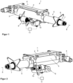
- Figure 1 shows an embodiment of the steering column 1 according to the invention in a perspective view obliquely from the rear left in the direction of vehicle travel.
- the steering column 1 comprises a support unit 2 and a casing unit 3.
- the casing unit 3 is connected to the support unit 2 via a pivot axis 4.
- the steering column 1 can be attached to a vehicle body of a motor vehicle (not shown in the figures) via the support unit 2.
- the support unit 2 serves to pivotably suspend the casing unit 3 and the associated actuating unit 5 on the vehicle body.
- the actuating unit 5 is accommodated in the casing unit 3.
- the actuating unit 5 is movably connected to the casing unit 3, i.e. the actuating unit 5 can be moved telescopically relative to the casing unit 3 by being pushed into the casing unit 3 and pulled out of the casing unit 3, thus making it adjustable relative to the support unit 2.
- the actuating unit 5 is designed as a tubular body with a flange 6 at the end facing the driver, i.e. on the steering wheel side.
- the flange 6 can be coupled to a steering column switch module (not shown in the figures).
- the tubular body of the actuating unit 5 is arranged coaxially in the casing unit 3 at the end facing away from the driver, namely it is mounted axially displaceably therein.
- the actuating unit 5 comprises a steering spindle 7.
- the steering column 1 thus comprises the steering spindle 7.
- the longitudinal axis of the steering spindle 7 defines a steering spindle axis 8.
- the steering spindle 7 is rotatably mounted in the actuating unit 5.
- the steering spindle 7 is therefore also rotatably mounted in the casing unit 3. This is because the actuating unit 5 is accommodated in the casing unit 3.
- the steering spindle 7 is mounted in the casing unit 3 with the actuating unit 5 interposed. It is also conceivable and possible that the steering spindle 7 is mounted directly in the casing unit 3.
- the steering column 1 comprises an adjusting device designed as a longitudinal adjusting device 9 for moving the steering spindle 7 relative to the support unit 2, namely for the translational movement of the adjusting unit 5 and thus the steering spindle 7 along the steering spindle axis 8 relative to the support unit 2 and relative to the casing unit 3.
- the longitudinal adjustment device 9 thus serves for the longitudinal adjustment of the actuating unit 5 and the steering spindle 7 mounted therein.
- the steering column 1 comprises an adjustment device designed as a height adjustment device 10 for pivoting the casing unit 3 together with the actuating unit 5 and thus the steering spindle 7 about the pivot axis 4 relative to the support unit 2.
- the height adjustment device 10 serves to adjust the height of the steering spindle 7.
- the steering column 1 further comprises a control device 11 designed as an Electronic Control Unit (ECU) for operating both adjustment devices 9, 10.
- the control device 11 comprises a monitoring device (not shown in the figures), which in turn comprises a computing unit 17 (see Figure 3 ).
- the monitoring device is designed to monitor the temperature of the adjustment devices 9, 10 and to influence the movement of the actuating unit 5 if it detects a fault, namely overheating or a state of thermal overload of one of the adjustment devices 9, 10.
- the monitoring device is also designed to detect a state of sufficient cooling of both the longitudinal adjustment device 9 and the height adjustment device 10.
- Figure 2 shows the steering column 1 from Figure 1 in another perspective view from the rear right in the direction of vehicle travel.
- Figure 3 shows a part of the steering column 1 from Figure 1 in the form of a block diagram.
- the control device 11 is connected to a current/voltage source 13, a user/driver input 14 and a bus system 15 via a first electrical interface 12. In addition, the control device 11 is connected to the longitudinal adjustment device 9 and the height adjustment device 10 via a second electrical interface 16.
- the computing unit 17 is designed as a microcontroller unit (MCU).
- the longitudinal adjustment device 9 and the height adjustment device 10 are each stored as a separate mathematical substitute model, namely as a Longitudinal adjustment device model 18 and a height adjustment device model 19.
- the control device 11 is designed to detect a state of thermal overload of the longitudinal adjustment device 9 on the basis of the longitudinal adjustment device model 18.
- the longitudinal adjustment device model 18 is a dynamic, thermal model of the longitudinal adjustment device 9. Accordingly, the control device 11 is further designed to detect a state of thermal overload of the height adjustment device 10 on the basis of the height adjustment device model 19.
- the height adjustment device model 19 is a dynamic, thermal model of the height adjustment device 10.
- the control device 11 comprises a power/voltage connection 20, a user/driver input interface 21 and a bus system interface 22, each of which is assigned to the computing unit 17.
- the computing unit 17 is connected to the current/voltage source 13 via the current/voltage connection 20. In this way, the computing unit 17 can be supplied with electrical energy.
- undesirable electrical or electromagnetic effects can occur, for example due to the current/voltage network, in particular electromagnetic interference, which disrupts the proper functioning of the computing unit 17 and thus the control device 11.
- an interference suppression filter 23 is provided, which is connected upstream of the current/voltage connection 20.
- the interference suppression filter 23 comprises an LC low-pass filter and reverse polarity protection.
- the computing unit 17 is connected to the user/driver input 14 via the user/driver input interface 21.
- the user/driver input 14 allows the user or driver of the motor vehicle to make an input relating to the longitudinal and/or height adjustment of the steering column 1. In other words: the user or driver can adjust the longitudinal and/or height position of the steering spindle 7 using the user/driver input 14.
- the computing unit 17 is connected to the bus system 15, for example a Local Interconnect Network (LIN) or a Controller Area Network (CAN), via the bus system interface 22.
- the bus system 15 is a communication system and is used to network subsystems, for example sensors and actuators, in relation to a mutual exchange of information, in particular exchange of sensor values and control signals.
- the control device 11 further comprises a longitudinal adjustment device driver 24 and a height adjustment device driver 25, which are each assigned to the computing unit 17.
- the adjustment device drivers 24, 25 each serve as a communication interface between the respective adjustment device model 18, 19 and the respective adjustment device 9, 10.
- the interference suppression of the control device 11 is indicated by an arrow from the interference suppression filter 23 to the adjustment device drivers 24, 25.
- Figure 4 shows an example of a network model of concentrated elements in a circuit diagram representation, namely the longitudinal adjustment device model 18 of the steering column 1 from Figure 1
- the height adjustment device model 19 can be constructed or formulated in an analogous manner.
- the longitudinal adjustment device model 18 ideally includes copper line heat losses 26, winding body heat losses 27, housing body heat losses 28 and ambient convection heat losses 29. Neglecting other heat losses simplifies the longitudinal adjustment device model 18 to the essential effects.
- the longitudinal adjustment device model 18 is therefore a particularly suitable model with regard to a balance between the model's precision and computational intensity. However, it is also conceivable and possible to take other heat losses into account or not to take one or more of the losses mentioned into account.
- the copper line heat losses 26 are shown as a current source P v,Cu .
- the winding body heat losses 27 are shown as a thermal capacitance C th,W with a thermal resistance R th,W , where a winding temperature difference ⁇ W is defined.
- the housing body heat losses 28 are shown as a thermal capacitance C th,G with a thermal resistance R th,G , where a housing temperature difference ⁇ G is defined.
- the ambient convection heat losses 29 are shown as a thermal resistance R th,G ⁇ U , where the ambient temperature ⁇ U is assumed to be constant.
Landscapes
- Engineering & Computer Science (AREA)
- Chemical & Material Sciences (AREA)
- Combustion & Propulsion (AREA)
- Transportation (AREA)
- Mechanical Engineering (AREA)
- Power Steering Mechanism (AREA)
- Steering Control In Accordance With Driving Conditions (AREA)
- Steering Controls (AREA)
Claims (7)
- Colonne de direction (1) pour un véhicule automobile, comprenant une unité de support (2), une unité d'ajustement (5) supportant de manière rotative un arbre de direction (7), qui est maintenue de manière réglable sur l'unité de support (2), un dispositif de réglage (9, 10) pour déplacer l'unité d'ajustement (5) par rapport à l'unité de support (2), un unité de commande (11) pour faire fonctionner le dispositif de réglage (9, 10), et un dispositif de surveillance qui est conçu pour influencer le mouvement de l'unité d'ajustement (5), lorsqu'une perturbation est détectée, caractérisé en ce que la perturbation est déterminée par la constatation d'une surcharge thermique, une unité de calcul (17) étant prévue, qui détermine la surcharge thermique à l'aide d'un modèle thermique dynamique (18, 19), le modèle thermique dynamique (18, 19) étant conçu de telle sorte qu'il est tenu compte d'une émission de chaleur dans l'environnement par l'intermédiaire de parties du boîtier de la colonne de direction (1) et/ou du dispositif de réglage (9, 10).
- Colonne de direction (1) selon la revendication 1, caractérisée en ce que le dispositif de réglage (9, 10) comprend un écrou de broche et une broche filetée qui s'y engage, l'écrou de broche et la broche filetée pouvant tourner l'un par rapport à l'autre et pouvant être entra nés par le servomoteur du dispositif de réglage (9, 10).
- Procédé pour faire fonctionner une colonne de direction réglable (1) pour un véhicule automobile, comprenant une unité de support (2), une unité d'ajustement (5) supportant de manière rotative un arbre de direction (7), qui est maintenue de manière réglable sur l'unité de support (2), un dispositif de réglage (9, 10) présentant un servomoteur électrique pour déplacer l'unité d'ajustement (5) par rapport à l'unité de support (2), un unité de commande (11) pour faire fonctionner le dispositif de réglage (9, 10), et un dispositif de surveillance qui est conçu pour surveiller la température du dispositif de réglage (9, 10) et/ou du unité de commande (11) et pour influencer le mouvement de l'unité d'ajustement (5), comprenant les étapes suivantes- émettre un ordre à l'unité de commande (11) pour déplacer l'unité d'ajustement (5) par rapport à l'unité de support (2) par le moyen de déplacement (9, 10) ;- détecter un état thermique du dispositif de réglage (9, 10) et/ou de l'unité de commande (11) à l'aide du dispositif de surveillance ;
la détection de l'état thermique s'effectuant à l'aide d'un modèle thermique dynamique (18, 19), et le modèle thermique dynamique (18, 19) étant conçu de telle sorte qu'il est tenu compte d'une émission de chaleur dans l'environnement par l'intermédiaire de parties du boîtier de la colonne de direction (1) et/ou du dispositif de réglage (9, 10) ;- émettre une commande pour réduire ou désactiver le mouvement de l'unité d'ajustement (5) commandé par l'unité de commande (11) lorsque l'état thermique est un état de surcharge. - Procédé selon la revendication 3, caractérisé en ce que le modèle thermique dynamique (18, 19) est conçu de telle sorte que des résistances de transfert de chaleur et/ou des capacités thermiques sont prises en compte.
- Procédé selon la revendication 3 ou la revendication 4, caractérisé en ce que le dispositif de réglage (9, 10) comprend un écrou de broche et une broche filetée qui s'y engage, l'écrou de broche et la broche filetée pouvant tourner l'un par rapport à l'autre et pouvant être entraînés par le servomoteur du dispositif de réglage (9).
- Procédé selon l'une des revendications 3 à 5, caractérisé en ce que le temps de fonctionnement du servomoteur et/ou la tension de fonctionnement du servomoteur et/ou le courant de fonctionnement du servomoteur et/ou la vitesse de fonctionnement du servomoteur et/ou la température ambiante est une grandeur d'entrée du modèle thermique (18, 19).
- Procédé selon l'une des revendications 3 à 6, caractérisé en ce que l'on prévoit l'étape supplémentaire suivante :- émettre une commande pour activer le mouvement de l'unité d'ajustement (5) commandé par l'unité de commande (11) lorsque l'état thermique est un état de fonctionnement normal après que le refroidissement a été effectué.
Applications Claiming Priority (2)
| Application Number | Priority Date | Filing Date | Title |
|---|---|---|---|
| DE102020105916.7A DE102020105916A1 (de) | 2020-03-05 | 2020-03-05 | Lenksäule für ein Kraftfahrzeug |
| PCT/EP2021/054991 WO2021175758A1 (fr) | 2020-03-05 | 2021-03-01 | Colonne de direction pour un véhicule à moteur |
Publications (2)
| Publication Number | Publication Date |
|---|---|
| EP4114709A1 EP4114709A1 (fr) | 2023-01-11 |
| EP4114709B1 true EP4114709B1 (fr) | 2025-02-12 |
Family
ID=74844905
Family Applications (1)
| Application Number | Title | Priority Date | Filing Date |
|---|---|---|---|
| EP21708982.0A Active EP4114709B1 (fr) | 2020-03-05 | 2021-03-01 | Colonne de direction pour un véhicule à moteur |
Country Status (4)
| Country | Link |
|---|---|
| EP (1) | EP4114709B1 (fr) |
| CN (1) | CN115243955A (fr) |
| DE (1) | DE102020105916A1 (fr) |
| WO (1) | WO2021175758A1 (fr) |
Families Citing this family (3)
| Publication number | Priority date | Publication date | Assignee | Title |
|---|---|---|---|---|
| JP7380445B2 (ja) * | 2020-06-25 | 2023-11-15 | 株式会社ジェイテクト | ステアリング装置、異常判断方法、および異常判断プログラム |
| DE102023108130A1 (de) * | 2023-03-30 | 2024-10-02 | Schaeffler Technologies AG & Co. KG | Verfahren zum Entriegeln einer einen Parksperrenaktor aufweisenden Parksperre für ein Kraftfahrzeug, sowie Parksperre für ein Kraftfahrzeug |
| US12570351B2 (en) | 2024-07-26 | 2026-03-10 | Steering Solutions Ip Holding Corporation | Pinch detection for column adjustment actuators |
Citations (2)
| Publication number | Priority date | Publication date | Assignee | Title |
|---|---|---|---|---|
| DE102015216326A1 (de) * | 2015-08-26 | 2016-06-23 | Thyssenkrupp Ag | Motorisch verstellbare Lenksäule für ein Kraftfahrzeug |
| DE102017207561A1 (de) * | 2017-05-05 | 2017-07-06 | Thyssenkrupp Ag | Lenksäule für ein Kraftfahrzeug und Verfahren zur Herstellung einer Lenksäule |
Family Cites Families (8)
| Publication number | Priority date | Publication date | Assignee | Title |
|---|---|---|---|---|
| DE102006019981A1 (de) | 2005-07-16 | 2007-01-18 | Brose Fahrzeugteile Gmbh & Co. Kommanditgesellschaft, Coburg | Verfahren und Vorrichtung einer Verstelleinrichtung eines Kraftfahrzeugs |
| JP4973159B2 (ja) * | 2006-11-30 | 2012-07-11 | 日本精工株式会社 | 電動式ステアリング装置 |
| US8412411B2 (en) | 2009-12-14 | 2013-04-02 | Robert Bosch Gmbh | Electronic control module heat limiting systems and methods |
| DE102010020087B4 (de) * | 2010-05-10 | 2013-05-16 | Thyssenkrupp Presta Ag | Regelverfahren für einen steuerbaren Energieabsorber |
| DE102015000029A1 (de) * | 2015-01-08 | 2016-07-14 | Thyssenkrupp Ag | Lenksäule mit adaptierbarer Schwenklagerung |
| JP7057548B2 (ja) * | 2016-09-27 | 2022-04-20 | 日本精工株式会社 | 内部衝撃吸収ステアリングコラム組立体のためのエネルギー吸収デバイス |
| DE102017201379A1 (de) * | 2017-01-30 | 2018-08-02 | Thyssenkrupp Ag | Motorisch verstellbare Lenksäule für ein Kraftfahrzeug und Verstellantrieb für eine Lenksäule |
| CN109861171A (zh) * | 2017-11-30 | 2019-06-07 | 上海航天汽车机电股份有限公司 | 用于汽车方向盘管柱位置调节控制装置的电机保护方法 |
-
2020
- 2020-03-05 DE DE102020105916.7A patent/DE102020105916A1/de active Pending
-
2021
- 2021-03-01 WO PCT/EP2021/054991 patent/WO2021175758A1/fr not_active Ceased
- 2021-03-01 EP EP21708982.0A patent/EP4114709B1/fr active Active
- 2021-03-01 CN CN202180019913.6A patent/CN115243955A/zh active Pending
Patent Citations (2)
| Publication number | Priority date | Publication date | Assignee | Title |
|---|---|---|---|---|
| DE102015216326A1 (de) * | 2015-08-26 | 2016-06-23 | Thyssenkrupp Ag | Motorisch verstellbare Lenksäule für ein Kraftfahrzeug |
| DE102017207561A1 (de) * | 2017-05-05 | 2017-07-06 | Thyssenkrupp Ag | Lenksäule für ein Kraftfahrzeug und Verfahren zur Herstellung einer Lenksäule |
Also Published As
| Publication number | Publication date |
|---|---|
| EP4114709A1 (fr) | 2023-01-11 |
| CN115243955A (zh) | 2022-10-25 |
| DE102020105916A1 (de) | 2021-09-09 |
| WO2021175758A1 (fr) | 2021-09-10 |
Similar Documents
| Publication | Publication Date | Title |
|---|---|---|
| WO2021175758A1 (fr) | Colonne de direction pour un véhicule à moteur | |
| DE112014004333B4 (de) | Servolenkungsvorrichtung und Steuervorrichtung für ein im Fahrzeug montiertes Gerät | |
| DE69322175T2 (de) | Vorrichtung zur thermischen Überwachung eines Elektromotors an Bord eines Fahrzeuges, inbesondere für ein Servolenkungssystem | |
| DE4018713C2 (de) | Scheibenwischvorrichtung | |
| DE60212500T2 (de) | Dämpfung beim Ausschalten einer elektrischen Servolenkung | |
| DE10360582B4 (de) | Elektromechanische Lenkung eines Kraftfahrzeugs | |
| DE112017000239T5 (de) | Lenkvorrichtung | |
| DE102018132148A1 (de) | Redundantes mechatronisches System | |
| EP3996970B1 (fr) | Procédé pour faire fonctionner une colonne de direction à ajustement motorisé, et colonne de direction à ajustement motorisé pour un véhicule à moteur | |
| DE102022001489B3 (de) | Verfahren zum Betrieb eines elektrischen Antriebssystems für ein Kraftfahrzeug | |
| EP0814327A1 (fr) | Méthode pour obtenir une saisie correcte de la température extérieure | |
| DE102021200428A1 (de) | Elektromechanisches Lenksystem für ein Kraftfahrzeug und Verfahren zum Betrieb eines Lenksystems für ein Kraftfahrzeug | |
| DE10316483A1 (de) | Thermisches Management eines Steuerungssystems für eine elektrische Servolenkung mittels Kompensation des Stroms des Steuerungs-Motors | |
| DE10115480A1 (de) | Schutzgerät für elektrische Lenkservoeinrichtung | |
| DE102023123575A1 (de) | Aufhängungssystem für ein arbeitsfahrzeug | |
| EP1970289B1 (fr) | Procédé destiné au fonctionnement d'un système de direction assistée électrique | |
| DE102013221951B4 (de) | Lenksystem und Verfahren zum Verringern einer in einem elektrisch unterstützten Lenksystem umgesetzten Leistung | |
| DE102013201677B4 (de) | Testverfahren zur Regelung und/oder Steuerung einer Lenkhilfe für ein Lenksystem eines Fahrzeuges | |
| WO2008113308A1 (fr) | Procédé de production d'un signal d'erreur indiquant un état de charge inacceptable pour un moteur électrique et appareil électrique de protection de moteur permettant la mise en oeuvre dudit procédé | |
| DE19740169C2 (de) | Verfahren und Vorrichtung zur Kontrolle der Temperaturregelung beheizbarer Vorrichtungen | |
| EP1593582A2 (fr) | Procédé de commande d'un système électrique de direction assistée | |
| DE4036134A1 (de) | Verfahren und einrichtung zur ueberwachung der temperatur von widerstaenden | |
| DE102005045715B4 (de) | Verfahren zur Begrenzung der Temperatur einer Endstufe eines Elektromotors | |
| WO2024175418A1 (fr) | Procédé de direction d'un véhicule à moteur à l'aide d'un système de direction à commande électrique, et système de direction à commande électrique | |
| EP1342648B1 (fr) | Système pour mesurer l'ampleur des rotations d'une colonne de direction |
Legal Events
| Date | Code | Title | Description |
|---|---|---|---|
| STAA | Information on the status of an ep patent application or granted ep patent |
Free format text: STATUS: UNKNOWN |
|
| STAA | Information on the status of an ep patent application or granted ep patent |
Free format text: STATUS: THE INTERNATIONAL PUBLICATION HAS BEEN MADE |
|
| PUAI | Public reference made under article 153(3) epc to a published international application that has entered the european phase |
Free format text: ORIGINAL CODE: 0009012 |
|
| STAA | Information on the status of an ep patent application or granted ep patent |
Free format text: STATUS: REQUEST FOR EXAMINATION WAS MADE |
|
| 17P | Request for examination filed |
Effective date: 20221005 |
|
| AK | Designated contracting states |
Kind code of ref document: A1 Designated state(s): AL AT BE BG CH CY CZ DE DK EE ES FI FR GB GR HR HU IE IS IT LI LT LU LV MC MK MT NL NO PL PT RO RS SE SI SK SM TR |
|
| DAV | Request for validation of the european patent (deleted) | ||
| DAX | Request for extension of the european patent (deleted) | ||
| GRAP | Despatch of communication of intention to grant a patent |
Free format text: ORIGINAL CODE: EPIDOSNIGR1 |
|
| STAA | Information on the status of an ep patent application or granted ep patent |
Free format text: STATUS: GRANT OF PATENT IS INTENDED |
|
| INTG | Intention to grant announced |
Effective date: 20241011 |
|
| GRAS | Grant fee paid |
Free format text: ORIGINAL CODE: EPIDOSNIGR3 |
|
| GRAA | (expected) grant |
Free format text: ORIGINAL CODE: 0009210 |
|
| STAA | Information on the status of an ep patent application or granted ep patent |
Free format text: STATUS: THE PATENT HAS BEEN GRANTED |
|
| AK | Designated contracting states |
Kind code of ref document: B1 Designated state(s): AL AT BE BG CH CY CZ DE DK EE ES FI FR GB GR HR HU IE IS IT LI LT LU LV MC MK MT NL NO PL PT RO RS SE SI SK SM TR |
|
| REG | Reference to a national code |
Ref country code: GB Ref legal event code: FG4D Free format text: NOT ENGLISH |
|
| REG | Reference to a national code |
Ref country code: CH Ref legal event code: EP |
|
| REG | Reference to a national code |
Ref country code: DE Ref legal event code: R096 Ref document number: 502021006623 Country of ref document: DE |
|
| REG | Reference to a national code |
Ref country code: DE Ref legal event code: R084 Ref document number: 502021006623 Country of ref document: DE |
|
| REG | Reference to a national code |
Ref country code: IE Ref legal event code: FG4D Free format text: LANGUAGE OF EP DOCUMENT: GERMAN |
|
| PGFP | Annual fee paid to national office [announced via postgrant information from national office to epo] |
Ref country code: AT Payment date: 20250417 Year of fee payment: 5 |
|
| REG | Reference to a national code |
Ref country code: NL Ref legal event code: MP Effective date: 20250212 |
|
| PG25 | Lapsed in a contracting state [announced via postgrant information from national office to epo] |
Ref country code: RS Free format text: LAPSE BECAUSE OF FAILURE TO SUBMIT A TRANSLATION OF THE DESCRIPTION OR TO PAY THE FEE WITHIN THE PRESCRIBED TIME-LIMIT Effective date: 20250512 |
|
| PG25 | Lapsed in a contracting state [announced via postgrant information from national office to epo] |
Ref country code: FI Free format text: LAPSE BECAUSE OF FAILURE TO SUBMIT A TRANSLATION OF THE DESCRIPTION OR TO PAY THE FEE WITHIN THE PRESCRIBED TIME-LIMIT Effective date: 20250212 |
|
| PG25 | Lapsed in a contracting state [announced via postgrant information from national office to epo] |
Ref country code: PL Free format text: LAPSE BECAUSE OF FAILURE TO SUBMIT A TRANSLATION OF THE DESCRIPTION OR TO PAY THE FEE WITHIN THE PRESCRIBED TIME-LIMIT Effective date: 20250212 |
|
| PG25 | Lapsed in a contracting state [announced via postgrant information from national office to epo] |
Ref country code: ES Free format text: LAPSE BECAUSE OF FAILURE TO SUBMIT A TRANSLATION OF THE DESCRIPTION OR TO PAY THE FEE WITHIN THE PRESCRIBED TIME-LIMIT Effective date: 20250212 |
|
| REG | Reference to a national code |
Ref country code: LT Ref legal event code: MG9D |
|
| PG25 | Lapsed in a contracting state [announced via postgrant information from national office to epo] |
Ref country code: NO Free format text: LAPSE BECAUSE OF FAILURE TO SUBMIT A TRANSLATION OF THE DESCRIPTION OR TO PAY THE FEE WITHIN THE PRESCRIBED TIME-LIMIT Effective date: 20250512 Ref country code: IS Free format text: LAPSE BECAUSE OF FAILURE TO SUBMIT A TRANSLATION OF THE DESCRIPTION OR TO PAY THE FEE WITHIN THE PRESCRIBED TIME-LIMIT Effective date: 20250612 |
|
| PG25 | Lapsed in a contracting state [announced via postgrant information from national office to epo] |
Ref country code: NL Free format text: LAPSE BECAUSE OF FAILURE TO SUBMIT A TRANSLATION OF THE DESCRIPTION OR TO PAY THE FEE WITHIN THE PRESCRIBED TIME-LIMIT Effective date: 20250212 |
|
| PG25 | Lapsed in a contracting state [announced via postgrant information from national office to epo] |
Ref country code: HR Free format text: LAPSE BECAUSE OF FAILURE TO SUBMIT A TRANSLATION OF THE DESCRIPTION OR TO PAY THE FEE WITHIN THE PRESCRIBED TIME-LIMIT Effective date: 20250212 |
|
| PG25 | Lapsed in a contracting state [announced via postgrant information from national office to epo] |
Ref country code: LV Free format text: LAPSE BECAUSE OF FAILURE TO SUBMIT A TRANSLATION OF THE DESCRIPTION OR TO PAY THE FEE WITHIN THE PRESCRIBED TIME-LIMIT Effective date: 20250212 Ref country code: PT Free format text: LAPSE BECAUSE OF FAILURE TO SUBMIT A TRANSLATION OF THE DESCRIPTION OR TO PAY THE FEE WITHIN THE PRESCRIBED TIME-LIMIT Effective date: 20250612 |
|
| PG25 | Lapsed in a contracting state [announced via postgrant information from national office to epo] |
Ref country code: GR Free format text: LAPSE BECAUSE OF FAILURE TO SUBMIT A TRANSLATION OF THE DESCRIPTION OR TO PAY THE FEE WITHIN THE PRESCRIBED TIME-LIMIT Effective date: 20250513 Ref country code: BG Free format text: LAPSE BECAUSE OF FAILURE TO SUBMIT A TRANSLATION OF THE DESCRIPTION OR TO PAY THE FEE WITHIN THE PRESCRIBED TIME-LIMIT Effective date: 20250212 |
|
| PG25 | Lapsed in a contracting state [announced via postgrant information from national office to epo] |
Ref country code: SE Free format text: LAPSE BECAUSE OF FAILURE TO SUBMIT A TRANSLATION OF THE DESCRIPTION OR TO PAY THE FEE WITHIN THE PRESCRIBED TIME-LIMIT Effective date: 20250212 |
|
| PG25 | Lapsed in a contracting state [announced via postgrant information from national office to epo] |
Ref country code: SM Free format text: LAPSE BECAUSE OF FAILURE TO SUBMIT A TRANSLATION OF THE DESCRIPTION OR TO PAY THE FEE WITHIN THE PRESCRIBED TIME-LIMIT Effective date: 20250212 |
|
| PG25 | Lapsed in a contracting state [announced via postgrant information from national office to epo] |
Ref country code: DK Free format text: LAPSE BECAUSE OF FAILURE TO SUBMIT A TRANSLATION OF THE DESCRIPTION OR TO PAY THE FEE WITHIN THE PRESCRIBED TIME-LIMIT Effective date: 20250212 |
|
| PG25 | Lapsed in a contracting state [announced via postgrant information from national office to epo] |
Ref country code: IT Free format text: LAPSE BECAUSE OF FAILURE TO SUBMIT A TRANSLATION OF THE DESCRIPTION OR TO PAY THE FEE WITHIN THE PRESCRIBED TIME-LIMIT Effective date: 20250212 |
|
| PG25 | Lapsed in a contracting state [announced via postgrant information from national office to epo] |
Ref country code: EE Free format text: LAPSE BECAUSE OF FAILURE TO SUBMIT A TRANSLATION OF THE DESCRIPTION OR TO PAY THE FEE WITHIN THE PRESCRIBED TIME-LIMIT Effective date: 20250212 Ref country code: CZ Free format text: LAPSE BECAUSE OF FAILURE TO SUBMIT A TRANSLATION OF THE DESCRIPTION OR TO PAY THE FEE WITHIN THE PRESCRIBED TIME-LIMIT Effective date: 20250212 |
|
| PG25 | Lapsed in a contracting state [announced via postgrant information from national office to epo] |
Ref country code: RO Free format text: LAPSE BECAUSE OF FAILURE TO SUBMIT A TRANSLATION OF THE DESCRIPTION OR TO PAY THE FEE WITHIN THE PRESCRIBED TIME-LIMIT Effective date: 20250212 |
|
| REG | Reference to a national code |
Ref country code: CH Ref legal event code: H13 Free format text: ST27 STATUS EVENT CODE: U-0-0-H10-H13 (AS PROVIDED BY THE NATIONAL OFFICE) Effective date: 20251024 |
|
| PG25 | Lapsed in a contracting state [announced via postgrant information from national office to epo] |
Ref country code: SK Free format text: LAPSE BECAUSE OF FAILURE TO SUBMIT A TRANSLATION OF THE DESCRIPTION OR TO PAY THE FEE WITHIN THE PRESCRIBED TIME-LIMIT Effective date: 20250212 |
|
| REG | Reference to a national code |
Ref country code: DE Ref legal event code: R097 Ref document number: 502021006623 Country of ref document: DE |
|
| PG25 | Lapsed in a contracting state [announced via postgrant information from national office to epo] |
Ref country code: LU Free format text: LAPSE BECAUSE OF NON-PAYMENT OF DUE FEES Effective date: 20250301 |
|
| REG | Reference to a national code |
Ref country code: BE Ref legal event code: MM Effective date: 20250331 |
|
| PLBE | No opposition filed within time limit |
Free format text: ORIGINAL CODE: 0009261 |
|
| STAA | Information on the status of an ep patent application or granted ep patent |
Free format text: STATUS: NO OPPOSITION FILED WITHIN TIME LIMIT |
|
| PG25 | Lapsed in a contracting state [announced via postgrant information from national office to epo] |
Ref country code: MC Free format text: LAPSE BECAUSE OF FAILURE TO SUBMIT A TRANSLATION OF THE DESCRIPTION OR TO PAY THE FEE WITHIN THE PRESCRIBED TIME-LIMIT Effective date: 20250212 |
|
| PG25 | Lapsed in a contracting state [announced via postgrant information from national office to epo] |
Ref country code: FR Free format text: LAPSE BECAUSE OF NON-PAYMENT OF DUE FEES Effective date: 20250412 |
|
| PG25 | Lapsed in a contracting state [announced via postgrant information from national office to epo] |
Ref country code: BE Free format text: LAPSE BECAUSE OF NON-PAYMENT OF DUE FEES Effective date: 20250331 |
|
| PG25 | Lapsed in a contracting state [announced via postgrant information from national office to epo] |
Ref country code: CH Free format text: LAPSE BECAUSE OF NON-PAYMENT OF DUE FEES Effective date: 20250331 |
|
| PG25 | Lapsed in a contracting state [announced via postgrant information from national office to epo] |
Ref country code: IE Free format text: LAPSE BECAUSE OF NON-PAYMENT OF DUE FEES Effective date: 20250301 |
|
| 26N | No opposition filed |
Effective date: 20251113 |
|
| GBPC | Gb: european patent ceased through non-payment of renewal fee |
Effective date: 20250512 |
|
| PG25 | Lapsed in a contracting state [announced via postgrant information from national office to epo] |
Ref country code: GB Free format text: LAPSE BECAUSE OF NON-PAYMENT OF DUE FEES Effective date: 20250512 |
|
| PGFP | Annual fee paid to national office [announced via postgrant information from national office to epo] |
Ref country code: DE Payment date: 20260319 Year of fee payment: 6 |