EP4114709B1 - Steering column for a motor vehicle - Google Patents
Steering column for a motor vehicle Download PDFInfo
- Publication number
- EP4114709B1 EP4114709B1 EP21708982.0A EP21708982A EP4114709B1 EP 4114709 B1 EP4114709 B1 EP 4114709B1 EP 21708982 A EP21708982 A EP 21708982A EP 4114709 B1 EP4114709 B1 EP 4114709B1
- Authority
- EP
- European Patent Office
- Prior art keywords
- unit
- adjusting device
- adjustment
- steering column
- thermal
- Prior art date
- Legal status (The legal status is an assumption and is not a legal conclusion. Google has not performed a legal analysis and makes no representation as to the accuracy of the status listed.)
- Active
Links
Images

Classifications
-
- B—PERFORMING OPERATIONS; TRANSPORTING
- B62—LAND VEHICLES FOR TRAVELLING OTHERWISE THAN ON RAILS
- B62D—MOTOR VEHICLES; TRAILERS
- B62D1/00—Steering controls, i.e. means for initiating a change of direction of the vehicle
- B62D1/02—Steering controls, i.e. means for initiating a change of direction of the vehicle vehicle-mounted
- B62D1/16—Steering columns
- B62D1/18—Steering columns yieldable or adjustable, e.g. tiltable
- B62D1/181—Steering columns yieldable or adjustable, e.g. tiltable with power actuated adjustment, e.g. with position memory
Definitions
- the present invention relates to a steering column for a motor vehicle, comprising a support unit, an actuating unit which rotatably supports a steering spindle and is adjustably mounted on the support unit, an adjusting device having an electric servomotor for moving the actuating unit relative to the support unit, a control device for operating the adjusting device, and a monitoring device which is designed to influence the movement of the actuating unit when a fault is detected.
- the present invention further relates to a method for operating an adjustable steering column for a motor vehicle.
- the actuating unit is adjustably mounted on the support unit, i.e. the actuating unit is carried by the support unit or arranged on the support unit and is displaceable or slidable or movable relative to the support unit.
- Steering columns for motor vehicles have a steering spindle, at the rear end of which, in the direction of travel and facing the driver, a steering wheel is arranged for the driver to apply a steering command or steering torque. This end is referred to as the steering wheel end of the steering spindle.
- the steering spindle is mounted so that it can rotate about its longitudinal axis in a casing unit, also referred to as a guide box or box swing arm, or in an actuating unit accommodated in the casing unit.
- the casing unit is supported by a support unit that can be attached to the vehicle body.
- the steering spindle is therefore also supported by the support unit.
- the steering spindle can be moved or displaced or adjusted relative to the support unit in at least one adjustment direction, with a separate adjustment device being provided for each adjustment direction.
- a longitudinal adjustment of the steering spindle can be achieved by the actuating unit being accommodated in the casing unit so that it can be moved telescopically in the direction of the longitudinal axis of the steering spindle.
- a height adjustment of the steering spindle can be achieved by the actuating unit or the casing unit that accommodates it being pivotably mounted on the support unit.
- Such steering columns are referred to as adjustable steering columns.
- the adjustment of the steering column or the steering spindle enclosed by the steering column in the longitudinal and vertical adjustment direction enables the setting of an ergonomically favorable steering wheel position relative to the driver's position in the operating position, also known as the driving or operating position, in which manual steering intervention or steering commands can be made.
- the longitudinal and vertical adjustment is also important for optimizing the driver's view of the display/instrument panel or the dashboard of the vehicle.
- a failure of the adjustment drive means that the steering column can no longer be adjusted, a failure of the adjustment drive can sometimes mean that the driver's safety is no longer guaranteed, for example because the driver can no longer operate the steering wheel safely and/or the steering wheel is positioned so unfavorably in relation to the driver in the event of a crash that there is an increased risk of injury if the driver hits the steering wheel.
- a method for protecting a motor for an adjustable steering column from excessive temperatures is known from CN 109 861 171 A
- a circuit is provided which disconnects the motor from the supply voltage when a certain temperature is exceeded.
- the DE 10 2006 019 981 A1 a method for controlling an adjustment device of a motor vehicle having a drive motor, wherein the adjustment device can be a steering wheel adjustment. It is disclosed that a temperature of a field effect transistor is monitored and a function restriction occurs if the detected temperature is greater than a temperature control threshold.
- the object of the present invention is to provide a steering column whose operation is reliable and safe and which has a simple structure.
- a steering column for a motor vehicle comprising a support unit, an actuating unit which rotatably supports a steering spindle and is adjustably mounted on the support unit, an adjusting device having an electric servomotor for moving the actuating unit relative to the support unit, a control device for operating the adjusting device, and a monitoring device which is designed to influence the movement of the actuating unit when a fault is detected.
- the fault is determined by detecting a thermal overload. This involves detecting a thermal overload of the adjustment device and/or the control device.
- the steering column according to the invention is therefore a steering column whose operation is reliable and safe and which has a simple structure.
- the proposed steering column does not require cooling of the thermally stressed components.
- the critical temperature is defined as the temperature at which the adjustment drive and/or the drive components and/or the control device can suffer irreversible damage, so that their function is at least partially impaired.
- the adjustment drive in particular the windings of the electric servomotor, and/or the drive components associated with the adjustment drive may heat up due to power losses, in particular due to ohmic losses and/or due to friction losses.
- the control device may also heat up.
- the possible operating time of the adjustment drive is correspondingly long and thus the possible thermal stress on the adjustment drive is correspondingly large.
- the safety of the driver is further increased because, for example, he can still operate the steering wheel sufficiently safely and/or, in the event of a crash, the steering wheel can be positioned so favorably in relation to the driver that there is a reduced risk of injury in the event of a possible impact of the driver on the steering wheel.
- the monitoring device can be designed as a temperature switch.
- a temperature switch preferably has two switching states, wherein in the first switching state the adjustment device and/or the control device is disconnected from an electrical power supply and in the second switching state the electrical power supply is enabled, i.e. the electrical line is not interrupted.
- the electrical line through which a supply voltage flows to the control unit and/or to the adjustment device is interrupted. This interruption effectively prevents further heating and an associated increase in temperature, so that damage that occurs as a result is prevented, since thermal overload is avoided.
- the temperature switch is designed in such a way that it is transferred from the second switching state to the first switching state when a first predetermined critical temperature is reached. After the temperature drops below the second predetermined critical temperature, the change from the first switching state to the second switching state occurs.
- the value of the temperature at which the change from the second switching state to the first switching state occurs is greater than the value of the temperature at which the change from the first switching state to the second switching state occurs.
- the value of the first predetermined critical temperature is greater than the value of the second predetermined critical temperature.
- the monitoring device is arranged in the adjustment drive and/or the control device.
- thermoswitch is designed to detect a temperature and, depending on the detected temperature, to assume a switching state corresponding to an assignment determined before the adjustment drive is put into operation. Such a switching state can include the generation of a specific control signal, for example a control signal that switches off the adjustment drive and/or the control device before the first predetermined critical temperature is reached or exceeded.
- the thermoswitch can be designed as a thermistor, in particular a PTC resistor (positive temperature coefficient resistor), also referred to as a PTC thermistor, as a thermal switch-off or thermal fuse or as a temperature switch, in particular a bimetal switch.
- the support unit can be attached to a vehicle body, with an actuating unit and thus a steering spindle that can be moved relative to the support unit being arranged on the support unit.
- the adjusting device can be used to move the actuating unit and thus to move the steering spindle relative to the support unit.
- the control device can be used to output or send control commands.
- the monitoring device can be used to monitor the temperature, i.e. to detect a state of thermal overload of the adjusting device and/or the control device.
- the monitoring device can be used to detect a state of sufficient cooling of the adjusting device and/or the control device.
- a state of sufficient cooling is one of the states referred to as a normal operating state.
- a normal operating state is a state in which the temperature is below the second predetermined critical temperature.
- the control device can be designed to deactivate the adjustment device and/or the control device if the monitoring device detects a state of thermal overload of the adjustment device and/or the control device.
- the control device can also be designed to activate or restart the adjustment device and/or the control device if the monitoring device detects a state of sufficient cooling of the adjustment device and/or the control device.
- the control device comprises the monitoring device.
- a computing unit is provided in the steering column, i.e. the steering column comprises a computing unit, wherein the computing unit determines the thermal overload with the aid of a dynamic, thermal model. This involves determining a thermal overload of the adjustment device and/or the control device.
- the control device can comprise the computing unit.
- the monitoring device can comprise the computing unit.
- the dynamic, thermal model can be stored in the computing unit, for example in the form of lookup tables or conversion tables, whereby the table values can be determined experimentally, i.e. through preliminary tests. It is conceivable to define a critical temperature, above which the movement of the actuating unit is reduced. Additionally or alternatively, it is conceivable to define a critical temperature, above which the movement of the actuating unit is deactivated or stopped. It is also possible to define a critical temperature relative to a definable maximum temperature. For example, it is conceivable to define a further critical temperature as the temperature that is 85% of the maximum temperature, in other words, 15% below the maximum temperature. Furthermore, it is conceivable to define a critical temperature based on the internal energy of the system of interest, in particular the adjustment device and/or the control device.
- one or more temperatures of or within the modeled adjustment device and/or control device can be calculated - depending on the specific formulation of the model.
- the model calculates the temperatures based on values from sensors that are in an electrically adjustable steering column are usually used or installed anyway. These sensor values form the input variables of the model.
- the temperatures to be monitored are calculated by the model on the basis of sensor values that are usually recorded in an electrically adjustable steering column, there is no need to use or install additional sensors. This reduces the complexity of the steering column structure and the measurement complexity of the steering column.
- the dynamic, thermal model is a mathematical replacement model of the at least one adjustment device for calculating the temperatures to be monitored in or on the adjustment device and/or control device.
- Each of the adjustment devices or control devices is mathematically represented by an individual model.
- the model is scalable and expandable, so that the real adjustment device or control device represented by the model can in principle be changed as desired.
- the model can in principle be changed as desired in terms of its level of detail, which means that - depending on the objective and the desired or acceptable amount of computation - more or less precise replacement models can be created or set up.
- the adjusting device comprises a spindle nut and a threaded spindle engaging therein, wherein the spindle nut and the threaded spindle are relatively can be rotated relative to one another and can be driven by the servomotor of the adjustment device.
- the spindle nut has an internal thread.
- the threaded spindle has an external thread and is in engagement with the spindle nut, so that the spindle nut and threaded spindle are operatively connected.
- These drive components can be driven by an adjustment drive, specifically by the electric servomotor, i.e. the spindle nut or the threaded spindle can be driven.
- a method for operating an adjustable steering column for a motor vehicle comprising a support unit, an actuating unit which rotatably supports a steering spindle and is adjustably mounted on the support unit, an adjusting device having an electric servomotor for moving the actuating unit relative to the support unit, a control device for operating the adjusting device, and a monitoring device which is designed to monitor the temperature of the adjusting device and/or the control device and to influence the movement of the actuating unit.
- the method comprises the steps of issuing a command to the control device for moving the actuating unit relative to the support unit by means of the adjustment device; detecting a thermal state of the adjustment device and/or the control device with the aid of the monitoring device; issuing a command for reducing or deactivating the movement of the actuating unit controlled by the control device if the thermal state is an overload state.
- a command to move the actuating unit relative to the support unit is issued to the control device by the adjusting device.
- the actuating unit and thus the steering spindle are moved by the adjusting device to set a steering wheel position relative to the support unit, specifically in the longitudinal and/or height adjustment direction.
- the driver can make his desired adjustment via a switch arrangement or that the vehicle can do so due to a change in state, such as when the driver gets in and out or when switching to an autonomous driving mode.
- a thermal state of the adjustment device and/or the control device is detected or recognized with the help of the monitoring device.
- the active adjustment device and possibly also the control device may heat up, for example due to ohmic losses.
- the monitoring device monitors one or several temperatures of the adjustment device and/or control device or temperatures at one point or at several points of the adjustment device and/or control device.
- the temperature monitoring by the monitoring device can take place during an adjustment process and preferably also after an adjustment process, for example for a predetermined time.
- a command is issued to reduce or deactivate the movement of the actuating unit controlled by the control device, namely in the case that the detected thermal state of the adjustment device and/or the control device is an overload state, i.e. a thermal overload state.
- the reduction of the movement i.e. the slowing down of the adjustment movement, can be carried out by reducing the energy supplied to the adjustment device, i.e. the electrical current or electrical voltage of the servo motor.
- the deactivation of the movement can be carried out by switching the relevant adjustment device off/on. Almost immediately after the deactivation of at least one adjustment device, it begins to cool down, in particular through convective heat transfer under the influence of the cooler ambient air. This is also referred to as the cooling phase.
- a state of sufficient cooling of the adjustment device and/or the control device is detected or recognized with the aid of the monitoring device, namely after a command to reduce or deactivate the movement of the actuating unit controlled by the control device has been issued.
- the state of sufficient cooling can be defined in various ways. For example, the state of sufficient cooling can be defined as having occurred when a definable cooling time has elapsed. Alternatively, the state of sufficient cooling can be defined as having occurred when at least one of the temperatures has dropped below a definable threshold value in the sense of a cooling temperature. Further alternatively, the state of sufficient cooling can be defined as having occurred when a definable cooling time has elapsed and at least one of the temperatures has dropped below a definable threshold value in the sense of a cooling temperature, the second predetermined critical temperature.
- the monitoring device has a temperature measuring device.
- This temperature measuring device is set up to measure the temperature which is used to determine the thermal state.
- the Temperature measuring device can be arranged in the control device and/or in the adjustment device.
- the temperature measuring device can be arranged at a location outside the control device and/or the adjustment device. This offers the advantage that the arrangement of the temperature measuring device is simpler and more cost-effective. In this case, a correlation can be established between the measured temperature and a temperature inside the control device and/or the adjustment device using previous tests, so that when the adjustment device is in operation, the measured temperature can be used to draw conclusions about the prevailing temperature inside the control device and/or the adjustment device.
- a critical temperature prevails inside the control device and/or the adjustment device and thus an overload condition.
- a command is then issued to reduce or deactivate the movement of the actuating unit controlled by the control device.
- the thermal state is detected using a dynamic, thermal model.
- a dynamic, thermal model are dynamic, thermal models of the adjustment device and/or the control device.
- the monitoring device can detect or recognize a state of thermal overload of the adjustment device and/or the control device on the basis of a respective dynamic, thermal model of the adjustment device and/or the control device as soon as a temperature of the adjustment device and/or the control device reaches or exceeds a definable threshold value, i.e. a critical temperature.
- a definable threshold value i.e. a critical temperature.
- the adjustment device and/or the control device - as a real subsystem of the steering column - must be mapped in advance using a suitable dynamic, thermal model or replacement model.
- care should be taken to choose a balanced compromise between the precision and computational intensity of the model.
- a highly precise model is more computationally intensive than a less precise model. Because temperatures are monitored using a dynamic thermal model, the use of additional sensors is no longer necessary. Thanks to the dynamic thermal model, manufacturing costs can be further reduced while operational reliability is increased. In this way, the complexity of the steering column structure and the measurement complexity of the steering column are reduced and the reliability of the steering column is increased.
- the dynamic thermal model is advantageously a network model of concentrated elements or a Lumped Parameter Thermal Network (LPTN).
- Concentrated elements are an idealization of the real components for the purpose of simplifying the model.
- a real line resistance is modeled as a single, i.e. concentrated resistance element, whereas the line connecting the concentrated resistance element is assumed to have no resistance.
- the dynamic thermal model can be a multi-body model that takes into account the dominant heat losses, i.e. those that dominate the adjustment device with regard to thermal effects, as heat sources. The dominant heat losses are characterized by the fact that they superimpose other heat losses.
- the model can ideally include copper line heat losses, winding body heat losses, housing body heat losses and/or ambient convection heat losses.
- the parameters of the model can be based on empirically determined values and validated with corresponding measurements.
- the dynamic thermal model is designed in such a way that heat transfer resistances and/or heat capacities are taken into account. It is also conceivable that the dynamic thermal model is designed in such a way that only heat transfer resistances and/or heat capacities are taken into account, so that other effects are not taken into account. This is a model simplification that represents a particularly suitable compromise between the precision and computational intensity of the model.
- the dynamic thermal model is designed in such a way that heat dissipation to the environment, in particular exclusively via housing parts of the steering column and/or the adjustment device and/or the control device, is taken into account.
- This model simplification limits the influence of the ambient temperature to the largest components of the steering column or the adjustment device or the control device that thermally interact with the ambient temperature, namely the respective housing parts. These housing parts represent the dominant heat exchangers. This is another particularly suitable compromise between the precision and computational intensity of the model.
- the adjustment device of the adjustable steering column comprises a spindle nut and a threaded spindle engaging therein, wherein the spindle nut and the threaded spindle are rotatable relative to one another and can be driven by the servomotor of the adjustment device.
- input variables or an input variable of the dynamic, thermal model are the operating time of the actuator, the operating voltage of the actuator, the operating current of the actuator and/or the operating speed of the actuator.
- the operating time of the actuator can be recorded individually for each adjustment process, namely starting with the start time of an adjustment movement and ending with the end time of the adjustment movement.
- the operating voltage of the actuator can be recorded by a voltage measuring sensor or voltmeter.
- the operating current of the actuator can be recorded by a current measuring sensor or ammeter.
- the operating speed of the actuator can be recorded by a speed measuring sensor or can be determined by the control unit.
- These sensor values that can be used as input variables for the model are values from sensors that are usually used or installed in an electrically adjustable steering column anyway. This is because an actuator is indispensable for an electrically adjustable steering column and the operating voltage of the actuator is typically observed for performance monitoring. Additional sensors for recording the aforementioned parameters are therefore not required. This reduces the complexity of the steering column structure and the measurement complexity of the steering column.
- an input variable of the dynamic thermal model can be the ambient temperature.
- the ambient temperature can be measured using a temperature sensor or a thermometer. Temperature sensors for measuring the ambient temperature are usually used or installed in a motor vehicle with an electrically adjustable steering column anyway, for example to show the driver the outside temperature. Additional sensors for measuring the ambient temperature are therefore not required. This also reduces the complexity of the structure of the steering column and the measurement complexity of the steering column.
- a command is issued to reduce the movement of the actuating unit controlled by the control device
- a command is issued to deactivate the movement of the actuating unit controlled by the control device.
- an attempt is first made to cause the temperature to drop again by slowing down the adjustment, i.e. to cool down. If the determined temperature falls below a predetermined limit temperature, the second predetermined critical temperature, which is preferably lower than the first predetermined critical temperature, the adjustment speed can be increased again, i.e. the adjustment device can be accelerated again.
- the adjustment device is deactivated after a predetermined time or if a second critical temperature is exceeded, which is above the previously mentioned critical temperature.
- the second critical temperature at which deactivation occurs is 10% higher than the first critical temperature.
- the predetermined time is less than or equal to 10 seconds.
- the predetermined time is greater than 1 second.
- a further method step is provided, namely the issuing of a command to activate the movement of the actuating unit controlled by the control device when the thermal state is a normal operating state after cooling has taken place.
- the normal operating state is a state in which the temperature of the adjusting device and/or the control device is below a certain limit temperature.
- This limit temperature i.e. the second predetermined critical temperature, is preferably lower than the first predetermined critical temperature, particularly preferably it is at least 10%, particularly preferably 25% lower than the first predetermined critical temperature.
- the control device issues a command that restores or activates the previously reduced or deactivated movement of the actuating unit when the monitoring device has detected a state of sufficient cooling of the adjusting device and/or control device.
- this is an acceleration of the movement.
- the acceleration can be carried out by increasing the energy supplied to the adjustment device, i.e. the electrical current or voltage of the actuator.
- this is an activation or reactivation of the movement.
- the activation or reactivation can be carried out by switching on/switching on the relevant adjustment device, i.e. its actuator.
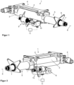
- Figure 1 shows an embodiment of the steering column 1 according to the invention in a perspective view obliquely from the rear left in the direction of vehicle travel.
- the steering column 1 comprises a support unit 2 and a casing unit 3.
- the casing unit 3 is connected to the support unit 2 via a pivot axis 4.
- the steering column 1 can be attached to a vehicle body of a motor vehicle (not shown in the figures) via the support unit 2.
- the support unit 2 serves to pivotably suspend the casing unit 3 and the associated actuating unit 5 on the vehicle body.
- the actuating unit 5 is accommodated in the casing unit 3.
- the actuating unit 5 is movably connected to the casing unit 3, i.e. the actuating unit 5 can be moved telescopically relative to the casing unit 3 by being pushed into the casing unit 3 and pulled out of the casing unit 3, thus making it adjustable relative to the support unit 2.
- the actuating unit 5 is designed as a tubular body with a flange 6 at the end facing the driver, i.e. on the steering wheel side.
- the flange 6 can be coupled to a steering column switch module (not shown in the figures).
- the tubular body of the actuating unit 5 is arranged coaxially in the casing unit 3 at the end facing away from the driver, namely it is mounted axially displaceably therein.
- the actuating unit 5 comprises a steering spindle 7.
- the steering column 1 thus comprises the steering spindle 7.
- the longitudinal axis of the steering spindle 7 defines a steering spindle axis 8.
- the steering spindle 7 is rotatably mounted in the actuating unit 5.
- the steering spindle 7 is therefore also rotatably mounted in the casing unit 3. This is because the actuating unit 5 is accommodated in the casing unit 3.
- the steering spindle 7 is mounted in the casing unit 3 with the actuating unit 5 interposed. It is also conceivable and possible that the steering spindle 7 is mounted directly in the casing unit 3.
- the steering column 1 comprises an adjusting device designed as a longitudinal adjusting device 9 for moving the steering spindle 7 relative to the support unit 2, namely for the translational movement of the adjusting unit 5 and thus the steering spindle 7 along the steering spindle axis 8 relative to the support unit 2 and relative to the casing unit 3.
- the longitudinal adjustment device 9 thus serves for the longitudinal adjustment of the actuating unit 5 and the steering spindle 7 mounted therein.
- the steering column 1 comprises an adjustment device designed as a height adjustment device 10 for pivoting the casing unit 3 together with the actuating unit 5 and thus the steering spindle 7 about the pivot axis 4 relative to the support unit 2.
- the height adjustment device 10 serves to adjust the height of the steering spindle 7.
- the steering column 1 further comprises a control device 11 designed as an Electronic Control Unit (ECU) for operating both adjustment devices 9, 10.
- the control device 11 comprises a monitoring device (not shown in the figures), which in turn comprises a computing unit 17 (see Figure 3 ).
- the monitoring device is designed to monitor the temperature of the adjustment devices 9, 10 and to influence the movement of the actuating unit 5 if it detects a fault, namely overheating or a state of thermal overload of one of the adjustment devices 9, 10.
- the monitoring device is also designed to detect a state of sufficient cooling of both the longitudinal adjustment device 9 and the height adjustment device 10.
- Figure 2 shows the steering column 1 from Figure 1 in another perspective view from the rear right in the direction of vehicle travel.
- Figure 3 shows a part of the steering column 1 from Figure 1 in the form of a block diagram.
- the control device 11 is connected to a current/voltage source 13, a user/driver input 14 and a bus system 15 via a first electrical interface 12. In addition, the control device 11 is connected to the longitudinal adjustment device 9 and the height adjustment device 10 via a second electrical interface 16.
- the computing unit 17 is designed as a microcontroller unit (MCU).
- the longitudinal adjustment device 9 and the height adjustment device 10 are each stored as a separate mathematical substitute model, namely as a Longitudinal adjustment device model 18 and a height adjustment device model 19.
- the control device 11 is designed to detect a state of thermal overload of the longitudinal adjustment device 9 on the basis of the longitudinal adjustment device model 18.
- the longitudinal adjustment device model 18 is a dynamic, thermal model of the longitudinal adjustment device 9. Accordingly, the control device 11 is further designed to detect a state of thermal overload of the height adjustment device 10 on the basis of the height adjustment device model 19.
- the height adjustment device model 19 is a dynamic, thermal model of the height adjustment device 10.
- the control device 11 comprises a power/voltage connection 20, a user/driver input interface 21 and a bus system interface 22, each of which is assigned to the computing unit 17.
- the computing unit 17 is connected to the current/voltage source 13 via the current/voltage connection 20. In this way, the computing unit 17 can be supplied with electrical energy.
- undesirable electrical or electromagnetic effects can occur, for example due to the current/voltage network, in particular electromagnetic interference, which disrupts the proper functioning of the computing unit 17 and thus the control device 11.
- an interference suppression filter 23 is provided, which is connected upstream of the current/voltage connection 20.
- the interference suppression filter 23 comprises an LC low-pass filter and reverse polarity protection.
- the computing unit 17 is connected to the user/driver input 14 via the user/driver input interface 21.
- the user/driver input 14 allows the user or driver of the motor vehicle to make an input relating to the longitudinal and/or height adjustment of the steering column 1. In other words: the user or driver can adjust the longitudinal and/or height position of the steering spindle 7 using the user/driver input 14.
- the computing unit 17 is connected to the bus system 15, for example a Local Interconnect Network (LIN) or a Controller Area Network (CAN), via the bus system interface 22.
- the bus system 15 is a communication system and is used to network subsystems, for example sensors and actuators, in relation to a mutual exchange of information, in particular exchange of sensor values and control signals.
- the control device 11 further comprises a longitudinal adjustment device driver 24 and a height adjustment device driver 25, which are each assigned to the computing unit 17.
- the adjustment device drivers 24, 25 each serve as a communication interface between the respective adjustment device model 18, 19 and the respective adjustment device 9, 10.
- the interference suppression of the control device 11 is indicated by an arrow from the interference suppression filter 23 to the adjustment device drivers 24, 25.
- Figure 4 shows an example of a network model of concentrated elements in a circuit diagram representation, namely the longitudinal adjustment device model 18 of the steering column 1 from Figure 1
- the height adjustment device model 19 can be constructed or formulated in an analogous manner.
- the longitudinal adjustment device model 18 ideally includes copper line heat losses 26, winding body heat losses 27, housing body heat losses 28 and ambient convection heat losses 29. Neglecting other heat losses simplifies the longitudinal adjustment device model 18 to the essential effects.
- the longitudinal adjustment device model 18 is therefore a particularly suitable model with regard to a balance between the model's precision and computational intensity. However, it is also conceivable and possible to take other heat losses into account or not to take one or more of the losses mentioned into account.
- the copper line heat losses 26 are shown as a current source P v,Cu .
- the winding body heat losses 27 are shown as a thermal capacitance C th,W with a thermal resistance R th,W , where a winding temperature difference ⁇ W is defined.
- the housing body heat losses 28 are shown as a thermal capacitance C th,G with a thermal resistance R th,G , where a housing temperature difference ⁇ G is defined.
- the ambient convection heat losses 29 are shown as a thermal resistance R th,G ⁇ U , where the ambient temperature ⁇ U is assumed to be constant.
Landscapes
- Engineering & Computer Science (AREA)
- Chemical & Material Sciences (AREA)
- Combustion & Propulsion (AREA)
- Transportation (AREA)
- Mechanical Engineering (AREA)
- Power Steering Mechanism (AREA)
- Steering Control In Accordance With Driving Conditions (AREA)
- Steering Controls (AREA)
Description
Die vorliegende Erfindung betrifft eine Lenksäule für ein Kraftfahrzeug, umfassend eine Trageinheit, eine eine Lenkspindel drehbar lagernde Stelleinheit, die an der Trageinheit verstellbar gehaltert ist, eine einen elektrischen Stellmotor aufweisende Verstelleinrichtung zum Bewegen der Stelleinheit relativ zu der Trageinheit, eine Steuerungseinrichtung zum Betreiben der Verstelleinrichtung, und eine Überwachungseinrichtung, die dazu eingerichtet ist, die Bewegung der Stelleinheit zu beeinflussen, wenn eine Störung detektiert wird. Des Weiteren betrifft die vorliegende Erfindung ein Verfahren zum Betreiben einer verstellbaren Lenksäule für ein Kraftfahrzeug.The present invention relates to a steering column for a motor vehicle, comprising a support unit, an actuating unit which rotatably supports a steering spindle and is adjustably mounted on the support unit, an adjusting device having an electric servomotor for moving the actuating unit relative to the support unit, a control device for operating the adjusting device, and a monitoring device which is designed to influence the movement of the actuating unit when a fault is detected. The present invention further relates to a method for operating an adjustable steering column for a motor vehicle.
Die Stelleinheit ist an der Trageinheit verstellbar gehaltert, das heißt, die Stelleinheit ist von der Trageinheit getragen bzw. an der Trageinheit angeordnet, und zwar relativ zu der Trageinheit verlagerbar bzw. verschiebbar bzw. bewegbar.The actuating unit is adjustably mounted on the support unit, i.e. the actuating unit is carried by the support unit or arranged on the support unit and is displaceable or slidable or movable relative to the support unit.
Lenksäulen für Kraftfahrzeuge weisen eine Lenkspindel auf, an deren in Fahrtrichtung hinteren, dem Fahrer zugewandten Ende ein Lenkrad zur Einbringung eines Lenkbefehls bzw. Lenkmoments durch den Fahrer angeordnet ist. Dieses Ende wird als lenkradseitiges Ende der Lenkspindel bezeichnet. Die Lenkspindel ist um ihre Längsachse in einer Manteleinheit, auch als Führungskasten oder Kastenschwinge bezeichnet, oder in einer in der Manteleinheit aufgenommenen Stelleinheit drehbar gelagert. Die Manteleinheit ist von einer Trageinheit getragen, die an der Fahrzeugkarosserie anbringbar ist. Somit ist auch die Lenkspindel von der Trageinheit getragen.Steering columns for motor vehicles have a steering spindle, at the rear end of which, in the direction of travel and facing the driver, a steering wheel is arranged for the driver to apply a steering command or steering torque. This end is referred to as the steering wheel end of the steering spindle. The steering spindle is mounted so that it can rotate about its longitudinal axis in a casing unit, also referred to as a guide box or box swing arm, or in an actuating unit accommodated in the casing unit. The casing unit is supported by a support unit that can be attached to the vehicle body. The steering spindle is therefore also supported by the support unit.
Die Lenkspindel ist zumindest in einer Verstellrichtung relativ zu der Trageinheit bewegbar bzw. verlagerbar bzw. verstellbar, wobei eine gesonderte Verstelleinrichtung je Verstellrichtung vorgesehen ist. Eine Längsverstellung der Lenkspindel kann dadurch verwirklicht werden, dass die Stelleinheit in der Manteleinheit in Richtung der Längsachse der Lenkspindel teleskopartig verschiebbar aufgenommen ist. Eine Höhenverstellung der Lenkspindel kann dadurch realisiert werden, dass die Stelleinheit oder die diese aufnehmende Manteleinheit verschwenkbar an der Trageinheit gelagert ist. Solche Lenksäulen werden als verstellbare Lenksäulen bezeichnet.The steering spindle can be moved or displaced or adjusted relative to the support unit in at least one adjustment direction, with a separate adjustment device being provided for each adjustment direction. A longitudinal adjustment of the steering spindle can be achieved by the actuating unit being accommodated in the casing unit so that it can be moved telescopically in the direction of the longitudinal axis of the steering spindle. A height adjustment of the steering spindle can be achieved by the actuating unit or the casing unit that accommodates it being pivotably mounted on the support unit. Such steering columns are referred to as adjustable steering columns.
Die Verstellung der Lenksäule bzw. der durch die Lenksäule umfassten Lenkspindel in Längs- und Höhenverstellrichtung ermöglicht die Einstellung einer ergonomisch günstigen Lenkradposition relativ zur Fahrerposition in Betriebsstellung, auch als Fahr- oder Bedienposition bezeichnet, in der ein manueller Lenkeingriff bzw. Lenkbefehl erfolgen kann. Die Längs- und Höhenverstellung ist ferner wichtig für die Optimierung der Sicht des Fahrers auf die Anzeige-/Instrumententafel bzw. auf das Armaturenbrett des Fahrzeugs.The adjustment of the steering column or the steering spindle enclosed by the steering column in the longitudinal and vertical adjustment direction enables the setting of an ergonomically favorable steering wheel position relative to the driver's position in the operating position, also known as the driving or operating position, in which manual steering intervention or steering commands can be made. The longitudinal and vertical adjustment is also important for optimizing the driver's view of the display/instrument panel or the dashboard of the vehicle.
Aus dem Stand der Technik, beispielsweise
Aus der
Es hat sich gezeigt, dass bei Lenksäulen mit einem großen bzw. langen Verstellweg die Ausfallrate von dem Verstellantrieb der Lenksäule zugeordneten Komponenten erhöht ist, wobei sich herausgestellt hat, dass regelmäßig eine starke Erwärmung hierfür die Ursache ist. Da bei einem Ausfall des Verstellantriebs keine Verstellung der Lenksäule mehr ermöglicht ist, kann ein Ausfall des Verstellantriebs dazu führen, dass mitunter die Sicherheit des Fahrzeugführers nicht mehr gewährleistet ist, da dieser beispielsweise das Lenkrad nicht mehr ausreichend sicher betätigen kann und/oder dieses im Crashfall derart ungünstig zu dem Fahrzeugführer positioniert ist, dass es zu einem erhöhten Verletzungsrisiko beim Aufprall des Fahrzeugführers auf das Lenkrad kommt.It has been shown that in steering columns with a large or long adjustment range, the failure rate of components associated with the steering column adjustment drive is increased, and it has been found that this is usually caused by excessive heating. Since a failure of the adjustment drive means that the steering column can no longer be adjusted, a failure of the adjustment drive can sometimes mean that the driver's safety is no longer guaranteed, for example because the driver can no longer operate the steering wheel safely and/or the steering wheel is positioned so unfavorably in relation to the driver in the event of a crash that there is an increased risk of injury if the driver hits the steering wheel.
Ein Verfahren zum Schutz eines Motors für eine verstellbare Lenksäule vor zu hohen Temperaturen ist aus der
Daher liegt der vorliegenden Erfindung die Aufgabe zugrunde, eine Lenksäule zur Verfügung zu stellen, deren Betrieb zuverlässig und sicher ist und die einen einfachen Aufbau hat.Therefore, the object of the present invention is to provide a steering column whose operation is reliable and safe and which has a simple structure.
Die der vorliegenden Erfindung zugrundeliegende Aufgabe wird gelöst durch eine Lenksäule für ein Kraftfahrzeug mit den Merkmalen des Anspruchs 1 sowie durch ein Verfahren mit den Merkmalen des Anspruchs 3. Vorteilhafte Weiterbildungen ergeben sich aus den jeweiligen Unteransprüchen.The object underlying the present invention is achieved by a steering column for a motor vehicle with the features of claim 1 and by a method with the features of
Es wird eine Lenksäule für ein Kraftfahrzeug vorgeschlagen, umfassend eine Trageinheit, eine eine Lenkspindel drehbar lagernde Stelleinheit, die an der Trageinheit verstellbar gehaltert ist, eine einen elektrischen Stellmotor aufweisende Verstelleinrichtung zum Bewegen der Stelleinheit relativ zu der Trageinheit, eine Steuerungseinrichtung zum Betreiben der Verstelleinrichtung, und eine Überwachungseinrichtung, die dazu eingerichtet ist, die Bewegung der Stelleinheit zu beeinflussen, wenn eine Störung detektiert wird.A steering column for a motor vehicle is proposed, comprising a support unit, an actuating unit which rotatably supports a steering spindle and is adjustably mounted on the support unit, an adjusting device having an electric servomotor for moving the actuating unit relative to the support unit, a control device for operating the adjusting device, and a monitoring device which is designed to influence the movement of the actuating unit when a fault is detected.
Erfindungsgemäß ist die Störung durch Feststellen einer thermischen Überlastung bestimmt. Dabei handelt es sich um ein Feststellen einer thermischen Überlastung der Verstelleinrichtung und/oder der Steuerungseinrichtung.According to the invention, the fault is determined by detecting a thermal overload. This involves detecting a thermal overload of the adjustment device and/or the control device.
Die erfindungsgemäße Lenksäule ist daher eine Lenksäule, deren Betrieb zuverlässig und sicher ist und die einen einfachen Aufbau hat. Insbesondere kommt die vorgeschlagene Lenksäule ohne eine Kühlung der thermisch beanspruchten Komponenten aus. Darüber hinaus entstehen vorteilhafterweise keine zusätzlichen Kosten durch die Verwendung von hitzeresistenteren Komponenten. Dank der erfindungsgemäßen Ausgestaltung der Lenksäule kann kostengünstig und zuverlässig ein irreversibler Schaden der Verstelleinrichtung und/oder der Steuerungseinrichtung wirksam vermieden werden, da die Bewegung, sprich die Verstellung der Stelleinheit, beeinflussbar ist, wenn eine thermische Überlastung festgestellt ist. Somit stellt diese Maßnahme einen wesentlichen Beitrag zur Erhöhung der Sicherheit des Fahrzeugführers dar.The steering column according to the invention is therefore a steering column whose operation is reliable and safe and which has a simple structure. In particular, the proposed steering column does not require cooling of the thermally stressed components. In addition, advantageously, no additional costs arise from the use of more heat-resistant components. Thanks to the design of the steering column according to the invention, irreversible damage to the adjustment device and/or the control device can be effectively avoided in a cost-effective and reliable manner, since the movement, i.e. the adjustment of the actuating unit, can be influenced if a thermal overload is detected. This measure therefore represents a significant contribution to increasing the safety of the vehicle driver.
Falls die Erwärmung des Verstellantriebs und/oder der Antriebskomponenten und/oder der Steuerungseinrichtung eine kritische Temperatur übersteigt, spricht man von thermischer Überlastung. Die kritische Temperatur ist als jene definiert, bei deren Überschreiten der Verstellantrieb und/oder der Antriebskomponenten und/oder der Steuerungseinrichtung einen irreversiblen Schaden nehmen kann, so dass deren Funktion zumindest teilweise beeinträchtigt ist.If the heating of the adjustment drive and/or the drive components and/or the control device exceeds a critical temperature, this is referred to as thermal overload. The critical temperature is defined as the temperature at which the adjustment drive and/or the drive components and/or the control device can suffer irreversible damage, so that their function is at least partially impaired.
Während des Betriebs des Verstellantriebs der Lenksäule, das heißt, während des Verstellens entlang des Verstellwegs kann es also aufgrund von Verlustleistungen, insbesondere aufgrund ohmscher Verluste und/oder aufgrund von Reibungsverlusten, zu einer Erwärmung des Verstellantriebs, insbesondere der Wicklungen des elektrischen Stellmotors, und/oder der dem Verstellantrieb zugeordneten Antriebskomponenten kommen. Es kann auch zu einer Erwärmung der Steuerungseinrichtung kommen. Bei besonders großen bzw. langen Verstellwegen und bei vielen Verstellzyklen in kurzer Zeit, wie diese beispielsweise in einem Missbrauchsfall auftreten können, ist die mögliche Betriebszeit des Verstellantriebs entsprechend lang und somit die mögliche thermische Beanspruchung des Verstellantriebs entsprechend groß.During operation of the steering column adjustment drive, i.e. during adjustment along the adjustment path, the adjustment drive, in particular the windings of the electric servomotor, and/or the drive components associated with the adjustment drive may heat up due to power losses, in particular due to ohmic losses and/or due to friction losses. The control device may also heat up. In the case of particularly large or long adjustment paths and in the case of many adjustment cycles in a short period of time, as can occur in the event of misuse, for example, the possible operating time of the adjustment drive is correspondingly long and thus the possible thermal stress on the adjustment drive is correspondingly large.
Vorteilhafterweise wird dank der vorgeschlagenen Lenksäule dabei eine zu hohe thermische Beanspruchung der Lenksäule durch frühzeitiges Feststellen einer thermischen Überlastung und die Beeinflussung der Bewegung der Stelleinheit beim Feststellen der thermischen Überlastung verhindert. Eine Zerstörung und/oder Beschädigung von deren Bauteilen wird somit vorteilhafterweise verhindert. Ebenso wird vorteilhafterweise verhindert, dass der elektrische Stellmotor aufgrund einer hohen thermischen Beanspruchung durchbrennt und/oder in seiner Leistungsfähigkeit geschädigt werden. Auch wird vorteilhafterweise verhindert, dass Schmiermittelschichten von Komponenten durch zu hohe Temperaturen zerstört werden. Dies macht den Betrieb der Lenksäule vorteilhafterweise zuverlässig und sicher, insbesondere da die Ausfallwahrscheinlichkeit des Verstellantriebs aufgrund einer thermischen Überlastung vorteilhafterweise signifikant reduziert ist.Advantageously, thanks to the proposed steering column, excessive thermal stress on the steering column is prevented by early detection of thermal overload and influencing the movement of the actuating unit when thermal overload is detected. Destruction and/or damage to its components is thus advantageously prevented. Likewise, it is advantageously prevented that the electric actuator burns out due to high thermal stress and/or its performance is damaged. It is also advantageously prevented that lubricant layers on components are destroyed by excessive temperatures. This makes the operation of the steering column advantageously reliable and safe, especially since the probability of failure of the adjustment drive due to thermal overload is advantageously significantly reduced.
Da das Bereitstehen der Funktion der Verstelleinrichtung und/oder der Steuerungseinrichtung der Lenksäule somit weiter verbessert ist, ist die Sicherheit des Fahrzeugführers weiter erhöht, da dieser beispielsweise das Lenkrad weiterhin ausreichend sicher betätigen kann und/oder dieses im Crashfall derart günstig zu dem Fahrzeugführer positioniert werden kann, dass es zu einem verringerten Verletzungsrisiko bei einem möglichen Aufprall des Fahrzeugführers auf das Lenkrad kommt.Since the availability of the function of the adjustment device and/or the control device of the steering column is thus further improved, the safety of the driver is further increased because, for example, he can still operate the steering wheel sufficiently safely and/or, in the event of a crash, the steering wheel can be positioned so favorably in relation to the driver that there is a reduced risk of injury in the event of a possible impact of the driver on the steering wheel.
In einer vorteilhaften Weiterbildung kann die Überwachungseinrichtung als Temperaturschalter ausgebildet sein. Ein solcher Temperaturschalter weist bevorzugt zwei Schaltzustände auf, wobei in dem ersten Schaltzustand die Verstelleinrichtung und/oder die Steuerungseinrichtung von einer elektrischen Spannungsversorgung getrennt ist und in dem zweiten Schaltzustand die elektrische Spannungsversorgung ermöglicht ist, sprich die elektrische Leitung nicht unterbrochen ist. Mit anderen Worten wird im Fall einer Störung durch eine thermische Überlastung die elektrische Leitung, durch die eine Versorgerspannung zu der Steuereinheit und/oder zu der Verstelleinrichtung fließt, unterbrochen. Durch diese Unterbrechung wird ein weiteres Erwärmen und eine damit verbundene Temperatursteigerung wirksam verhindert, so dass ein dadurch auftretender Schaden verhindert wird, da eine thermische Überlastung vermieden wird. Der Temperaturschalter ist derart ausgelegt, dass dieser bei dem Erreichen einer ersten vorbestimmten kritischen Temperatur von dem zweiten Schaltzustand in den ersten Schaltzustand überführt wird. Nach einem Abfall der Temperatur unterhalb der zweiten vorbestimmten kritischen Temperatur erfolgt der Wechsel von dem ersten Schaltzustand in den zweiten Schaltzustand.In an advantageous development, the monitoring device can be designed as a temperature switch. Such a temperature switch preferably has two switching states, wherein in the first switching state the adjustment device and/or the control device is disconnected from an electrical power supply and in the second switching state the electrical power supply is enabled, i.e. the electrical line is not interrupted. In other words, in the event of a fault due to thermal overload, the electrical line through which a supply voltage flows to the control unit and/or to the adjustment device is interrupted. This interruption effectively prevents further heating and an associated increase in temperature, so that damage that occurs as a result is prevented, since thermal overload is avoided. The temperature switch is designed in such a way that it is transferred from the second switching state to the first switching state when a first predetermined critical temperature is reached. After the temperature drops below the second predetermined critical temperature, the change from the first switching state to the second switching state occurs.
Bevorzugt ist der Wert der Temperatur, bei dem der Wechsel von dem zweiten Schaltzustand in den ersten Schaltzustand erfolgt, größer als der Wert der Temperatur, bei dem der Wechsel von dem ersten Schaltzustand in den zweiten Schaltzustand erfolgt. Das heißt dass der Wert der ersten vorbestimmten kritischen Temperatur größer ist als der Wert der zweiten vorbestimmten kritischen Temperatur. Beide Temperaturwerte werden bevorzugt in Testreihen während der Entwicklung ermittelt.Preferably, the value of the temperature at which the change from the second switching state to the first switching state occurs is greater than the value of the temperature at which the change from the first switching state to the second switching state occurs. This means that the value of the first predetermined critical temperature is greater than the value of the second predetermined critical temperature. Both temperature values are preferably determined in test series during development.
In einer vorteilhaften Weiterbildung kann es vorgesehen sein, dass die Überwachungseinrichtung in dem Verstellantrieb und/oder der Steuerungseinrichtung angeordnet ist.In an advantageous further development, it can be provided that the monitoring device is arranged in the adjustment drive and/or the control device.
Ein Thermoswitch ist dazu ausgebildet, eine Temperatur zu erfassen und in Abhängigkeit von der erfassten Temperatur, einen einer vor der Inbetriebnahme des Verstellantriebs festgelegten Zuweisung entsprechenden Schaltzustand einzunehmen. Ein solcher Schaltzustand kann die Erzeugung eines bestimmten Steuersignals umfassen, beispielsweise ein Steuersignal, das den Verstellantrieb und/oder die Steuerungseinrichtung vor Erreichen oder Überschreiten der ersten vorbestimmten kritischen Temperatur abschaltet. Der Thermoswitch kann als Thermistor, insbesondere PTC-Widerstand (Positive Temperature Coefficient Widerstand), auch als Kaltleiter bezeichnet, als thermische Abschaltung bzw. Thermosicherung oder Temperaturschalter, insbesondere Bimetallschalter, ausgebildet sein.A thermoswitch is designed to detect a temperature and, depending on the detected temperature, to assume a switching state corresponding to an assignment determined before the adjustment drive is put into operation. Such a switching state can include the generation of a specific control signal, for example a control signal that switches off the adjustment drive and/or the control device before the first predetermined critical temperature is reached or exceeded. The thermoswitch can be designed as a thermistor, in particular a PTC resistor (positive temperature coefficient resistor), also referred to as a PTC thermistor, as a thermal switch-off or thermal fuse or as a temperature switch, in particular a bimetal switch.
Die Trageinheit kann an einer Fahrzeugkarosserie anbringbar sein, wobei an der Trageinheit eine relativ zu der Trageinheit bewegbare Stelleinheit und somit Lenkspindel angeordnet ist. Die Verstelleinrichtung kann zum Bewegen der Stelleinheit und somit zum Bewegen der Lenkspindel relativ zu der Trageinheit dienen. Die Steuerungseinrichtung kann zum Ausgeben bzw. Aussenden von Steuerbefehlen dienen. Die Überwachungseinrichtung kann zur Temperaturüberwachung, das heißt, zum Erkennen eines Zustands thermischer Überlastung der Verstelleinrichtung und/oder der Steuerungseinrichtung dienen. Die Überwachungseinrichtung kann zum Erkennen eines Zustands hinreichender Abkühlung der Verstelleinrichtung und/oder der Steuerungseinrichtung dienen. Ein Zustand hinreichender Abkühlung ist einer der als Normalbetriebszustand bezeichneten Zustände. Ein Normalbetriebszustand ist ein Zustand, in dem die Temperatur unterhalb der zweiten vorbestimmten kritischen Temperatur liegt. Bevorzugterweise ist nur in einem Normalbetriebszustand eine Verstellung bzw. Bewegung der jeweiligen Verstelleinrichtung bei Nenngeschwindigkeit möglich. Die Steuerungseinrichtung kann derart ausgebildet sein, die Verstelleinrichtung und/oder die Steuerungseinrichtung zu deaktivieren, wenn die Überwachungseinrichtung einen Zustand thermischer Überlastung der Verstelleinrichtung und/oder der Steuerungseinrichtung erkennt. Die Steuerungseinrichtung kann auch derart ausgebildet sein, die Verstelleinrichtung und/oder die Steuerungseinrichtung zu aktivieren bzw. wieder zu starten, wenn die Überwachungseinrichtung einen Zustand hinreichender Abkühlung der Verstelleinrichtung und/oder der Steuerungseinrichtung erkennt. In einer vorteilhaften Weiterbildung kann es vorgesehen sein, dass die Steuerungseinrichtung die Überwachungseinrichtung umfasst.The support unit can be attached to a vehicle body, with an actuating unit and thus a steering spindle that can be moved relative to the support unit being arranged on the support unit. The adjusting device can be used to move the actuating unit and thus to move the steering spindle relative to the support unit. The control device can be used to output or send control commands. The monitoring device can be used to monitor the temperature, i.e. to detect a state of thermal overload of the adjusting device and/or the control device. The monitoring device can be used to detect a state of sufficient cooling of the adjusting device and/or the control device. A state of sufficient cooling is one of the states referred to as a normal operating state. A normal operating state is a state in which the temperature is below the second predetermined critical temperature. Preferably, only in one In the normal operating state, an adjustment or movement of the respective adjustment device at nominal speed is possible. The control device can be designed to deactivate the adjustment device and/or the control device if the monitoring device detects a state of thermal overload of the adjustment device and/or the control device. The control device can also be designed to activate or restart the adjustment device and/or the control device if the monitoring device detects a state of sufficient cooling of the adjustment device and/or the control device. In an advantageous development, it can be provided that the control device comprises the monitoring device.
Erfindungsgemäß ist in der Lenksäule eine Recheneinheit vorgesehen, das heißt, umfasst die Lenksäule eine Recheneinheit, wobei die Recheneinheit mit Hilfe eines dynamischen, thermischen Modells die thermische Überlastung bestimmt. Es handelt sich um die Bestimmung einer thermischen Überlastung der Verstelleinrichtung und/oder der Steuerungseinrichtung. Die Steuerungseinrichtung kann die Recheneinheit umfassen. Alternativ kann die Überwachungseinrichtung die Recheneinheit umfassen.According to the invention, a computing unit is provided in the steering column, i.e. the steering column comprises a computing unit, wherein the computing unit determines the thermal overload with the aid of a dynamic, thermal model. This involves determining a thermal overload of the adjustment device and/or the control device. The control device can comprise the computing unit. Alternatively, the monitoring device can comprise the computing unit.
Das dynamische, thermische Modell ist in der Recheneinheit beispielsweise in Form von Lookup-Tabellen bzw. Umsetzungstabellen hinterlegbar, wobei die Tabellenwerte auf experimentelle Weise, das heißt, durch Vorversuche ermittelt werden können. Es ist denkbar, eine kritische Temperatur zu definieren, bei deren Überschreitung die Bewegung der Stelleinheit reduziert wird. Zusätzlich oder alternativ ist es denkbar, eine kritische Temperatur zu definieren, bei deren Überschreitung die Bewegung der Stelleinheit deaktiviert bzw. gestoppt wird. Auch ist es möglich, eine kritische Temperatur relativ zu einer festlegbaren Maximaltemperatur zu definieren. Beispielsweise ist es denkbar, eine weitere kritische Temperatur als jene Temperatur zu definieren, die 85 % der Maximaltemperatur beträgt, mit anderen Worten, 15 % unterhalb der Maximaltemperatur liegt. Des Weiteren ist es denkbar, eine kritische Temperatur zu definieren auf Grundlage der inneren Energie des interessierenden Systems, insbesondere der Verstelleinrichtung und/oder der Steuerungseinrichtung.The dynamic, thermal model can be stored in the computing unit, for example in the form of lookup tables or conversion tables, whereby the table values can be determined experimentally, i.e. through preliminary tests. It is conceivable to define a critical temperature, above which the movement of the actuating unit is reduced. Additionally or alternatively, it is conceivable to define a critical temperature, above which the movement of the actuating unit is deactivated or stopped. It is also possible to define a critical temperature relative to a definable maximum temperature. For example, it is conceivable to define a further critical temperature as the temperature that is 85% of the maximum temperature, in other words, 15% below the maximum temperature. Furthermore, it is conceivable to define a critical temperature based on the internal energy of the system of interest, in particular the adjustment device and/or the control device.
Durch die Hinterlegung eines die Verstelleinrichtung und/oder Steuerungseinrichtung abbildenden Modells kann bzw. können - je nach konkreter Formulierung des Modells - eine Temperatur bzw. mehrere Temperaturen der bzw. innerhalb der modellierten Verstelleinrichtung und/oder Steuerungseinrichtung berechnet werden. Das Modell berechnet die Temperaturen auf Grundlage von Werten von Sensoren, die in einer elektrisch verstellbaren Lenksäule ohnehin üblicherweise eingesetzt bzw. verbaut sind. Diese Sensorwerte bilden die Eingangsgrößen des Modells.By storing a model that represents the adjustment device and/or control device, one or more temperatures of or within the modeled adjustment device and/or control device can be calculated - depending on the specific formulation of the model. The model calculates the temperatures based on values from sensors that are in an electrically adjustable steering column are usually used or installed anyway. These sensor values form the input variables of the model.
Dadurch, dass die zu überwachenden Temperaturen durch das Modell auf Grundlage von ohnehin üblicherweise in einer elektrisch verstellbaren Lenksäule erfassten Sensorwerten berechnet werden, erübrigt sich der Einsatz bzw. das Verbauen zusätzlicher Sensoren. Dies reduziert die Komplexität des Aufbaus der Lenksäule und die messtechnische Komplexität der Lenksäule.Because the temperatures to be monitored are calculated by the model on the basis of sensor values that are usually recorded in an electrically adjustable steering column, there is no need to use or install additional sensors. This reduces the complexity of the steering column structure and the measurement complexity of the steering column.
So kann ein Zustand thermischer Überlastung der Verstelleinrichtung und/oder der Steuerungseinrichtung auf Basis eines dynamischen, thermischen Modells der zumindest einen Verstelleinrichtung und/oder der Steuerungseinrichtung erkannt werden. Bei dem dynamischen, thermischen Modell handelt sich um ein mathematisches Ersatzmodell der zumindest einen Verstelleinrichtung zur Berechnung der zu überwachenden Temperaturen der bzw. in der Verstelleinrichtung und/oder Steuerungseinrichtung. Jede der Verstelleinrichtungen oder Steuerungseinrichtung ist durch ein individuelles Modell mathematisch abgebildet. Das Modell ist skalierbar und erweiterbar, sodass die jeweils durch das Modell repräsentierte reale Verstelleinrichtung oder Steuerungseinrichtung grundsätzlich beliebig veränderbar ist. Außerdem ist das Modell grundsätzlich beliebig in seinem Detaillierungsgrad veränderbar, das heißt, es können - je nach Zielsetzung und erwünschtem bzw. vertretbarem Rechenaufwand - mehr oder weniger präzise Ersatzmodelle gebildet bzw. aufgestellt werden. Je mehr Modellvereinfachungen getroffen werden, desto unpräziser ist das Modell. Präzisere Modelle bilden die Realität besser ab, sind jedoch rechenaufwändiger. Umgekehrt gilt: Unpräzisere Modelle bilden die Realität weniger gut ab, sind hingegen recheneffizienter.In this way, a state of thermal overload of the adjustment device and/or the control device can be detected on the basis of a dynamic, thermal model of the at least one adjustment device and/or the control device. The dynamic, thermal model is a mathematical replacement model of the at least one adjustment device for calculating the temperatures to be monitored in or on the adjustment device and/or control device. Each of the adjustment devices or control devices is mathematically represented by an individual model. The model is scalable and expandable, so that the real adjustment device or control device represented by the model can in principle be changed as desired. In addition, the model can in principle be changed as desired in terms of its level of detail, which means that - depending on the objective and the desired or acceptable amount of computation - more or less precise replacement models can be created or set up. The more model simplifications are made, the less precise the model is. More precise models depict reality better, but are more computationally complex. The opposite is true: less precise models represent reality less well, but are more computationally efficient.
Auf diese Weise erübrigt sich der Einsatz eines sogenannten Thermoswitches bzw. Thermoschalters in der Lenksäule, um eine thermische Überlastung des Verstellantriebs und/oder der Antriebskomponenten und/oder der Steuerungseinrichtung abzuwenden, das heißt, erwärmungs- bzw. überhitzungsbedingtes Versagen des Verstellantriebs und/oder der Antriebskomponenten und/oder der Steuerungseinrichtung zu verhindern. Dies reduziert die Herstellungskosten, vereinfacht die strukturelle und messtechnische Komplexität, wodurch wiederum die Wahrscheinlichkeit von messtechnischen Fehlern reduziert wird, sodass die Zuverlässigkeit und Betriebssicherheit der Lenksäule erhöht wird.This eliminates the need to use a so-called thermal switch in the steering column to prevent thermal overload of the adjustment drive and/or the drive components and/or the control device, i.e. to prevent heating or overheating-related failure of the adjustment drive and/or the drive components and/or the control device. This reduces manufacturing costs, simplifies structural and metrological complexity, which in turn reduces the likelihood of metrological errors, thus increasing the reliability and operational safety of the steering column.
Bevorzugterweise umfasst die Verstelleinrichtung eine Spindelmutter und eine darin eingreifende Gewindespindel, wobei die Spindelmutter und die Gewindespindel relativ zueinander drehbar sind und durch den Stellmotor der Verstelleinrichtung antreibbar sind. Die Spindelmutter weist ein Innengewinde auf. Die Gewindespindel weist ein Außengewinde auf und steht mit der Spindelmutter im Eingriff, sodass Spindelmutter und Gewindespindel wirkverbunden sind. Diese Antriebskomponenten sind von einem Verstellantrieb, im Konkreten von dem elektrischen Stellmotor antreibbar, das heißt, die Spindelmutter oder die Gewindespindel sind antreibbar.Preferably, the adjusting device comprises a spindle nut and a threaded spindle engaging therein, wherein the spindle nut and the threaded spindle are relatively can be rotated relative to one another and can be driven by the servomotor of the adjustment device. The spindle nut has an internal thread. The threaded spindle has an external thread and is in engagement with the spindle nut, so that the spindle nut and threaded spindle are operatively connected. These drive components can be driven by an adjustment drive, specifically by the electric servomotor, i.e. the spindle nut or the threaded spindle can be driven.
Des Weiteren wird in erfindungsgemäßer Weise ein Verfahren vorgeschlagen zum Betreiben einer verstellbaren Lenksäule für ein Kraftfahrzeug, umfassend eine Trageinheit, eine eine Lenkspindel drehbar lagernde Stelleinheit, die an der Trageinheit verstellbar gehaltert ist, eine einen elektrischen Stellmotor aufweisende Verstelleinrichtung zum Bewegen der Stelleinheit relativ zu der Trageinheit, eine Steuerungseinrichtung zum Betreiben der Verstelleinrichtung, und eine Überwachungseinrichtung, die dazu eingerichtet ist, die Temperatur der Verstelleinrichtung und/oder der Steuerungseinrichtung zu überwachen und die Bewegung der Stelleinheit zu beeinflussen.Furthermore, in accordance with the invention, a method is proposed for operating an adjustable steering column for a motor vehicle, comprising a support unit, an actuating unit which rotatably supports a steering spindle and is adjustably mounted on the support unit, an adjusting device having an electric servomotor for moving the actuating unit relative to the support unit, a control device for operating the adjusting device, and a monitoring device which is designed to monitor the temperature of the adjusting device and/or the control device and to influence the movement of the actuating unit.
Das Verfahren umfasst die Schritte Ausgeben eines Befehls an die Steuerungseinrichtung zum Bewegen der Stelleinheit relativ zu der Trageinheit durch die Verstelleinrichtung; Detektieren eines thermischen Zustands der Verstelleinrichtung und/oder der Steuerungseinrichtung mit Hilfe der Überwachungseinrichtung; Ausgeben eines Befehls zur Reduzierung oder Deaktivierung der durch die Steuerungseinrichtung gesteuerten Bewegung der Stelleinheit, wenn der thermische Zustand ein Überlastzustand ist.The method comprises the steps of issuing a command to the control device for moving the actuating unit relative to the support unit by means of the adjustment device; detecting a thermal state of the adjustment device and/or the control device with the aid of the monitoring device; issuing a command for reducing or deactivating the movement of the actuating unit controlled by the control device if the thermal state is an overload state.
In dem ersten Verfahrensschritt wird ein Befehl zum Bewegen der Stelleinheit relativ zur Trageinheit durch die Verstelleinrichtung an die Steuerungseinrichtung ausgegeben. Dadurch wird die Stelleinheit und somit die Lenkspindel zur Einstellung einer Lenkradposition relativ zu der Trageinheit durch die Verstelleinrichtung bewegt, und zwar in Längs- und/oder Höhenverstellrichtung. Dazu kann es beispielsweise vorgesehen sein, dass der Fahrer über eine Schalteranordnung seine gewünschte Verstellung ein oder das Fahrzeug aufgrund eines Zustandswechsels wie beim Ein- und Aussteigen des Fahrers oder bei einem Umschalten in einem autonomen Fahrmodus.In the first method step, a command to move the actuating unit relative to the support unit is issued to the control device by the adjusting device. As a result, the actuating unit and thus the steering spindle are moved by the adjusting device to set a steering wheel position relative to the support unit, specifically in the longitudinal and/or height adjustment direction. For this purpose, it can be provided, for example, that the driver can make his desired adjustment via a switch arrangement or that the vehicle can do so due to a change in state, such as when the driver gets in and out or when switching to an autonomous driving mode.
In dem weiteren Verfahrensschritt wird ein thermischer Zustand der Verstelleinrichtung und/oder der Steuerungseinrichtung mit Hilfe der Überwachungseinrichtung detektiert bzw. erkannt. Während eines jeden Verstellvorgangs erwärmt sich gegebenenfalls die jeweils aktive Verstelleinrichtung und gegebenenfalls auch die Steuerungseinrichtung, beispielsweise durch ohmsche Verluste. Die Überwachungseinrichtung überwacht eine oder mehrere Temperaturen der Verstelleinrichtung und/oder Steuerungseinrichtung bzw. Temperaturen an einer Stelle oder an mehreren Stellen der Verstelleinrichtung und/oder Steuerungseinrichtung. Die Temperaturüberwachung durch die Überwachungseinrichtung kann während eines Verstellvorgangs bevorzugt auch nach einem Verstellvorgang, beispielsweise für eine vorbestimmte Zeit erfolgen.In the next step, a thermal state of the adjustment device and/or the control device is detected or recognized with the help of the monitoring device. During each adjustment process, the active adjustment device and possibly also the control device may heat up, for example due to ohmic losses. The monitoring device monitors one or several temperatures of the adjustment device and/or control device or temperatures at one point or at several points of the adjustment device and/or control device. The temperature monitoring by the monitoring device can take place during an adjustment process and preferably also after an adjustment process, for example for a predetermined time.
In dem weiteren Verfahrensschritt wird ein Befehl zur Reduzierung oder Deaktivierung der durch die Steuerungseinrichtung gesteuerten Bewegung der Stelleinheit ausgegeben, nämlich in dem Fall, dass der detektierte thermische Zustand der Verstelleinrichtung und/oder der Steuerungseinrichtung ein Überlastzustand, das heißt, ein thermischer Überlastzustand, ist. Die Reduzierung der Bewegung, sprich die Verlangsamung der Verstellbewegung, kann durch Verringerung der der Verstelleinrichtung zugeführten Energie, das heißt, elektrische Stromstärke oder elektrische Spannung des Stellmotors, vollzogen werden. Die Deaktivierung der Bewegung kann durch Aus-/Abschaltung der betreffenden Verstelleinrichtung vollzogen werden. Nahezu unmittelbar nach der Deaktivierung der zumindest einen Verstelleinrichtung beginnt diese sich abzukühlen, insbesondere durch konvektive Wärmeübertragung unter Einfluss der kühleren Umgebungsluft. Dies wird auch als Abkühlphase bezeichnet.In the next step of the method, a command is issued to reduce or deactivate the movement of the actuating unit controlled by the control device, namely in the case that the detected thermal state of the adjustment device and/or the control device is an overload state, i.e. a thermal overload state. The reduction of the movement, i.e. the slowing down of the adjustment movement, can be carried out by reducing the energy supplied to the adjustment device, i.e. the electrical current or electrical voltage of the servo motor. The deactivation of the movement can be carried out by switching the relevant adjustment device off/on. Almost immediately after the deactivation of at least one adjustment device, it begins to cool down, in particular through convective heat transfer under the influence of the cooler ambient air. This is also referred to as the cooling phase.
In vorteilhafter Weise wird ein Zustand hinreichender Abkühlung der Verstelleinrichtung und/oder der Steuerungseinrichtung mit Hilfe der Überwachungseinrichtung detektiert bzw. erkannt, und zwar nachdem ein Befehl zur Reduzierung oder Deaktivierung der durch die Steuerungseinrichtung gesteuerten Bewegung der Stelleinheit ausgegeben worden ist. Der Zustand hinreichender Abkühlung ist auf verschiedene Weisen definierbar. Zum Beispiel ist der Zustand hinreichender Abkühlung als eingetreten definierbar, wenn eine festlegbare Abkühlzeit abgelaufen ist. Alternativ ist der Zustand hinreichender Abkühlung als eingetreten definierbar, wenn zumindest eine der Temperaturen unter einen festlegbaren Schwellwert im Sinne einer Abkühltemperatur abgesunken ist. Weiter alternativ ist der Zustand hinreichender Abkühlung als eingetreten definierbar, wenn eine festlegbare Abkühlzeit abgelaufen ist und zumindest eine der Temperaturen unter einen festlegbaren Schwellwert im Sinne einer Abkühltemperatur, der zweiten vorbestimmten kritischen Temperatur, abgesunken ist.Advantageously, a state of sufficient cooling of the adjustment device and/or the control device is detected or recognized with the aid of the monitoring device, namely after a command to reduce or deactivate the movement of the actuating unit controlled by the control device has been issued. The state of sufficient cooling can be defined in various ways. For example, the state of sufficient cooling can be defined as having occurred when a definable cooling time has elapsed. Alternatively, the state of sufficient cooling can be defined as having occurred when at least one of the temperatures has dropped below a definable threshold value in the sense of a cooling temperature. Further alternatively, the state of sufficient cooling can be defined as having occurred when a definable cooling time has elapsed and at least one of the temperatures has dropped below a definable threshold value in the sense of a cooling temperature, the second predetermined critical temperature.
In einer vorteilhaften Weiterbildung kann es vorgesehen sein, dass die Überwachungseinrichtung eine Temperaturmesseinrichtung aufweist. Diese Temperaturmesseinrichtung ist derart eingerichtet, die Temperatur zur Messen, die zur Bestimmung des thermischen Zustands verwendet wird. Bevorzugt kann die Temperaturmesseinrichtung in der Steuerungseinrichtung und/oder in der Verstelleinrichtung angeordnet sein. Alternativ oder zusätzlich kann die Temperaturmesseinrichtung an einer Stelle außerhalb der Steuerungseinrichtung und/oder der Verstelleinrichtung angeordnet. Dies bietet den Vorteil, dass die Anordnung der Temperaturmesseinrichtung einfacher und kostengünstiger möglich ist. Dabei kann mittels vorangehenden Untersuchungen eine Korrelation zwischen der gemessenen Temperatur und einer Temperatur im Inneren der Steuerungseinrichtung und/oder der Verstelleinrichtung aufgestellt werden, so dass im Betrieb der Verstelleinrichtung durch die gemessene Temperatur ein Rückschluss auf die vorherrschende Temperatur im Inneren der Steuerungseinrichtung und/oder der Verstelleinrichtung geschlossen werden kann. Erreicht oder übersteigt die gemessene Temperatur einen vorher durch die Korrelation festgelegten Schwellwert, so herrscht im Inneren der Steuerungseinrichtung und/oder der Verstelleinrichtung eine kritische Temperatur und somit ein Überlastzustand. Daraufhin wird ein Befehl zur Reduzierung oder Deaktivierung der durch die Steuerungseinrichtung gesteuerten Bewegung der Stelleinheit ausgegeben.In an advantageous development, it can be provided that the monitoring device has a temperature measuring device. This temperature measuring device is set up to measure the temperature which is used to determine the thermal state. Preferably, the Temperature measuring device can be arranged in the control device and/or in the adjustment device. Alternatively or additionally, the temperature measuring device can be arranged at a location outside the control device and/or the adjustment device. This offers the advantage that the arrangement of the temperature measuring device is simpler and more cost-effective. In this case, a correlation can be established between the measured temperature and a temperature inside the control device and/or the adjustment device using previous tests, so that when the adjustment device is in operation, the measured temperature can be used to draw conclusions about the prevailing temperature inside the control device and/or the adjustment device. If the measured temperature reaches or exceeds a threshold value previously determined by the correlation, a critical temperature prevails inside the control device and/or the adjustment device and thus an overload condition. A command is then issued to reduce or deactivate the movement of the actuating unit controlled by the control device.
Erfindungsgemäß erfolgt das Detektieren des thermischen Zustands mit Hilfe eines dynamischen, thermischen Modells. Und zwar handelt es sich dabei jeweils um dynamische, thermische Modelle der Verstelleinrichtung und/oder der Steuerungseinrichtung. Die Überwachungseinrichtung kann einen Zustand thermischer Überlastung der Verstelleinrichtung und/oder der Steuerungseinrichtung auf Basis eines jeweiligen dynamischen, thermischen Modells der Verstelleinrichtung und/oder der Steuerungseinrichtung detektieren bzw. erkennen, sobald eine Temperatur der Verstelleinrichtung und/oder der Steuerungseinrichtung einen festlegbaren Schwellwert, das heißt, eine kritische Temperatur, erreicht oder übersteigt. Dazu ist die Verstelleinrichtung und/oder die Steuerungseinrichtung - als reales Teilsystem der Lenksäule - im Vorfeld durch ein geeignetes dynamisches, thermisches Modell bzw. Ersatzmodell abzubilden. Im Allgemeinen sollte bei der Modellbildung darauf geachtet werden, einen ausgewogenen Kompromiss aus Präzision und Rechenintensität des Modells zu wählen. Ein hochpräzises Modell ist rechenintensiver als ein weniger präzises Modell. Dadurch, dass mit Hilfe eines dynamischen, thermischen Modells die Temperaturen überwacht werden, erübrigt sich der Einsatz zusätzlicher Sensoren. Dank des dynamischen, thermischen Modells können die Herstellungskosten weiter reduziert werden und gleichzeitig die Betriebssicherheit erhöht werden. Auf diese Weise ist die Komplexität des Aufbaus der Lenksäule und die messtechnische Komplexität der Lenksäule reduziert und die Zuverlässigkeit der Lenksäule erhöht.According to the invention, the thermal state is detected using a dynamic, thermal model. These are dynamic, thermal models of the adjustment device and/or the control device. The monitoring device can detect or recognize a state of thermal overload of the adjustment device and/or the control device on the basis of a respective dynamic, thermal model of the adjustment device and/or the control device as soon as a temperature of the adjustment device and/or the control device reaches or exceeds a definable threshold value, i.e. a critical temperature. For this purpose, the adjustment device and/or the control device - as a real subsystem of the steering column - must be mapped in advance using a suitable dynamic, thermal model or replacement model. In general, when creating the model, care should be taken to choose a balanced compromise between the precision and computational intensity of the model. A highly precise model is more computationally intensive than a less precise model. Because temperatures are monitored using a dynamic thermal model, the use of additional sensors is no longer necessary. Thanks to the dynamic thermal model, manufacturing costs can be further reduced while operational reliability is increased. In this way, the complexity of the steering column structure and the measurement complexity of the steering column are reduced and the reliability of the steering column is increased.
In vorteilhafter Weise ist das dynamische, thermische Modell ein Netzwerkmodell konzentrierter Elemente bzw. ein Lumped Parameter Thermal Network (LPTN). Konzentrierte Elemente sind eine Idealisierung der realen Bauelemente zum Zweck der Modellvereinfachung. Dabei ist beispielsweise ein realer Leitungswiderstand als ein einziges, das heißt, konzentriertes Widerstandselement modelliert, wohingegen die das konzentrierte Widerstandselement verbindende Leitung als widerstandslos angenommen wird. Im Konkreten kann das dynamische, thermische Modell ein die dominanten, das heißt, die Verstelleinrichtung im Hinblick auf thermische Effekte dominierenden, Wärmeverluste als Wärmequellen berücksichtigendes Mehrkörpermodell sein. Die dominanten Wärmeverluste zeichnen sich dadurch aus, dass sie andere Wärmeverluste überlagern.The dynamic thermal model is advantageously a network model of concentrated elements or a Lumped Parameter Thermal Network (LPTN). Concentrated elements are an idealization of the real components for the purpose of simplifying the model. For example, a real line resistance is modeled as a single, i.e. concentrated resistance element, whereas the line connecting the concentrated resistance element is assumed to have no resistance. In concrete terms, the dynamic thermal model can be a multi-body model that takes into account the dominant heat losses, i.e. those that dominate the adjustment device with regard to thermal effects, as heat sources. The dominant heat losses are characterized by the fact that they superimpose other heat losses.
Das Modell kann in idealisierender Weise Kupferleitungswärmeverluste, Wicklungskörperwärmeverluste, Gehäusekörperwärmeverluste und/oder Umgebungskonvektionswärmeverluste umfassen. Die Parameter des Modells können auf empirisch ermittelten Werten basieren und mit entsprechenden Messungen validiert werden. In weiter vorteilhafter Weise ist das dynamische, thermische Modell derart ausgebildet, dass Wärmeübergangswiderstände und/oder Wärmekapazitäten berücksichtigt sind. Es ist auch denkbar, dass das dynamische, thermische Modell derart ausgebildet ist, dass ausschließlich Wärmeübergangswiderstände und/oder Wärmekapazitäten berücksichtigt sind, sodass darüberhinausgehende Effekte unberücksichtigt bleiben. Dabei handelt es sich um eine Modellvereinfachung, die einen besonders geeigneten Kompromiss aus Präzision und Rechenintensität des Modells darstellt.The model can ideally include copper line heat losses, winding body heat losses, housing body heat losses and/or ambient convection heat losses. The parameters of the model can be based on empirically determined values and validated with corresponding measurements. In a further advantageous manner, the dynamic thermal model is designed in such a way that heat transfer resistances and/or heat capacities are taken into account. It is also conceivable that the dynamic thermal model is designed in such a way that only heat transfer resistances and/or heat capacities are taken into account, so that other effects are not taken into account. This is a model simplification that represents a particularly suitable compromise between the precision and computational intensity of the model.
Das dynamische, thermische Modell ist erfindungsgemäß derart ausgebildet, dass eine, insbesondere ausschließlich, über Gehäuseteile der Lenksäule und/oder der Verstelleinrichtung und/oder der Steuerungseinrichtung an die Umgebung erfolgende Wärmeabgabe berücksichtigt ist. Diese Modellvereinfachung beschränkt den Einfluss der Umgebungstemperatur auf die größten Bestandteile der Lenksäule oder der Verstelleinrichtung oder der Steuerungseinrichtung, die mit der Umgebungstemperatur thermisch wechselwirken, nämlich die jeweiligen Gehäuseteile. Diese Gehäuseteile stellen die dominierenden Wärmetauscher dar. Dies ist ein weiterer besonders geeigneter Kompromiss aus Präzision und Rechenintensität des Modells.According to the invention, the dynamic thermal model is designed in such a way that heat dissipation to the environment, in particular exclusively via housing parts of the steering column and/or the adjustment device and/or the control device, is taken into account. This model simplification limits the influence of the ambient temperature to the largest components of the steering column or the adjustment device or the control device that thermally interact with the ambient temperature, namely the respective housing parts. These housing parts represent the dominant heat exchangers. This is another particularly suitable compromise between the precision and computational intensity of the model.
Weiter ist denkbar, dass die Verstelleinrichtung der verstellbaren Lenksäule eine Spindelmutter und eine darin eingreifende Gewindespindel umfasst, wobei die Spindelmutter und die Gewindespindel relativ zueinander drehbar sind und durch den Stellmotor der Verstelleinrichtung antreibbar sind.It is further conceivable that the adjustment device of the adjustable steering column comprises a spindle nut and a threaded spindle engaging therein, wherein the spindle nut and the threaded spindle are rotatable relative to one another and can be driven by the servomotor of the adjustment device.
Bevorzugterweise sind Eingangsgrößen bzw. ist eine Eingangsgröße des dynamischen, thermischen Modells die Betriebszeit des Stellmotors, die Betriebsspannung des Stellmotors, der Betriebsstrom des Stellmotors und/oder die Betriebsdrehzahl des Stellmotors. Die Betriebszeit des Stellmotors ist für jeden Verstellvorgang einzeln erfassbar, nämlich jeweils beginnend mit dem Anfangszeitpunkt einer Verstellbewegung und endend mit dem Beendigungszeitpunkt der Verstellbewegung. Die Betriebsspannung des Stellmotors ist durch einen Spannungsmesssensor bzw. Voltmeter erfassbar. Der Betriebsstrom des Stellmotors ist durch einen Strommesssensor bzw. Amperemeter erfassbar. Die Betriebsdrehzahl des Stellmotors ist durch einen Drehzahlmesssensor erfassbar oder kann durch die Steuerungseinheit bestimmt werden. Bei diesen als Eingangsgrößen für das Modell verwendbaren Sensorwerten handelt es sich um Werte von Sensoren, die bei einer elektrisch verstellbaren Lenksäule ohnehin üblicherweise eingesetzt bzw. verbaut sind. Denn ein Stellmotor ist für eine elektrisch verstellbare Lenksäule unentbehrlich und die Betriebsspannung des Stellmotors wird typischerweise zur Leistungsüberwachung beobachtet. Zusätzliche Sensoren zur Erfassung der vorgenannten Kenngrößen sind somit nicht erforderlich. So reduziert sich die Komplexität des Aufbaus der Lenksäule und die messtechnische Komplexität der Lenksäule.Preferably, input variables or an input variable of the dynamic, thermal model are the operating time of the actuator, the operating voltage of the actuator, the operating current of the actuator and/or the operating speed of the actuator. The operating time of the actuator can be recorded individually for each adjustment process, namely starting with the start time of an adjustment movement and ending with the end time of the adjustment movement. The operating voltage of the actuator can be recorded by a voltage measuring sensor or voltmeter. The operating current of the actuator can be recorded by a current measuring sensor or ammeter. The operating speed of the actuator can be recorded by a speed measuring sensor or can be determined by the control unit. These sensor values that can be used as input variables for the model are values from sensors that are usually used or installed in an electrically adjustable steering column anyway. This is because an actuator is indispensable for an electrically adjustable steering column and the operating voltage of the actuator is typically observed for performance monitoring. Additional sensors for recording the aforementioned parameters are therefore not required. This reduces the complexity of the steering column structure and the measurement complexity of the steering column.
Zusätzlich oder alternativ kann eine Eingangsgröße des dynamischen, thermischen Modells die Umgebungstemperatur sein. Die Umgebungstemperatur ist durch einen Temperaturfühler bzw. ein Thermometer erfassbar. Temperaturfühler zur Erfassung der Umgebungstemperatur sind bei einem Kraftfahrzeug mit einer elektrisch verstellbaren Lenksäule ohnehin üblicherweise eingesetzt bzw. verbaut, um beispielsweise dem Fahrer die Außentemperatur anzuzeigen. Zusätzliche Sensoren zur Erfassung der Umgebungstemperatur sind somit nicht erforderlich. So reduziert sich ebenfalls die Komplexität des Aufbaus der Lenksäule und die messtechnische Komplexität der Lenksäule.Additionally or alternatively, an input variable of the dynamic thermal model can be the ambient temperature. The ambient temperature can be measured using a temperature sensor or a thermometer. Temperature sensors for measuring the ambient temperature are usually used or installed in a motor vehicle with an electrically adjustable steering column anyway, for example to show the driver the outside temperature. Additional sensors for measuring the ambient temperature are therefore not required. This also reduces the complexity of the structure of the steering column and the measurement complexity of the steering column.
Dies ermöglicht das sogenannte Derating, das heißt, eine an die Umgebungstemperatur angepasste Leistungsabgabe. Es handelt sich um eine von der Umgebungstemperatur abhängige Leistungsanpassung bzw. -reduzierung. Danach gilt ab einer festlegbaren, kritischen Umgebungstemperatur: Je höher die Umgebungstemperatur ist, desto geringer ist die Leistung bzw. Leistungsfähigkeit bzw. Leistungsabgabe des durch Derating überwachten elektrischen bzw. elektronischen Systems. Derating dient zum Überhitzungsschutz.This enables so-called derating, i.e. a power output adapted to the ambient temperature. This is a power adjustment or reduction dependent on the ambient temperature. After that, the following applies from a definable, critical ambient temperature: the higher the ambient temperature, the lower the the performance or efficiency or power output of the electrical or electronic system monitored by derating. Derating serves as overheating protection.
In einer vorteilhaften Weiterbildung kann es vorgesehen sein, dass in einem ersten Schritt bei der Detektierung des thermischen Überlastzustands durch die Überwachungseinrichtung ein Befehl zur Reduzierung durch die Steuerungseinrichtung gesteuerten Bewegung der Stelleinheit ausgegeben wird, wobei in einem zweiten Schritt, wenn nach einer vorbestimmten Zeit durch die Überwachungseinrichtung immer noch ein thermischer Überlastzustand detektiert wird, ein Befehl zur Deaktivierung der durch die Steuerungseinrichtung gesteuerten Bewegung der Stelleinheit ausgegeben wird. Mit anderen Worten wird zunächst durch eine Verlangsamung der Verstellung versucht, dass die Temperatur wieder absinkt, also eine Abkühlung stattfindet. Unterschreitet die ermittelte Temperatur eine vorbestimmte Grenztemperatur, die zweite vorbestimmte kritische Temperatur, die bevorzugt geringer ist als die erste vorbestimmte kritische Temperatur, kann die Verstellgeschwindigkeit wieder erhöht werden, sprich die Verstelleinrichtung wieder beschleunigt werden. Sollte jedoch die Temperatur nicht absinken, sondern oberhalb der kritischen Temperatur verharren, so erfolgt nach einer vorbestimmten Zeit oder bei einem Überschreiten einer zweiten kritischen Temperatur, die über der zuvor genannten kritischen Temperatur liegt, ein Deaktivieren der Verstelleinrichtung. Bevorzugt ist die zweite kritische Temperatur, bei der die Deaktivierung erfolgt, 10% höher als die erste kritische Temperatur. Bevorzugt ist die vorbestimmte Zeit kleiner gleich 10 Sekunden. Bevorzugt ist die vorbestimmte Zeit größer 1 Sekunde.In an advantageous further development, it can be provided that in a first step, when the thermal overload state is detected by the monitoring device, a command is issued to reduce the movement of the actuating unit controlled by the control device, and in a second step, if a thermal overload state is still detected by the monitoring device after a predetermined time, a command is issued to deactivate the movement of the actuating unit controlled by the control device. In other words, an attempt is first made to cause the temperature to drop again by slowing down the adjustment, i.e. to cool down. If the determined temperature falls below a predetermined limit temperature, the second predetermined critical temperature, which is preferably lower than the first predetermined critical temperature, the adjustment speed can be increased again, i.e. the adjustment device can be accelerated again. However, if the temperature does not drop but remains above the critical temperature, the adjustment device is deactivated after a predetermined time or if a second critical temperature is exceeded, which is above the previously mentioned critical temperature. Preferably, the second critical temperature at which deactivation occurs is 10% higher than the first critical temperature. Preferably, the predetermined time is less than or equal to 10 seconds. Preferably, the predetermined time is greater than 1 second.
In einer weiteren, bevorzugten Ausführungsform ist ein weiterer Verfahrensschritt vorgesehen, nämlich das Ausgeben eines Befehls zur Aktivierung der durch die Steuerungseinrichtung gesteuerten Bewegung der Stelleinheit, wenn der thermische Zustand ein Normalbetriebszustand nach erfolgter Abkühlung ist. Der Normalbetriebszustand ist ein solcher Zustand, bei der die Temperatur der Verstelleinrichtung und/oder der Steuerungseinrichtung unterhalb einer bestimmten Grenztemperatur liegt. Diese Grenztemperatur, also die zweite vorbestimmte kritische Temperatur, ist bevorzugt geringer als die erste vorbestimmte kritische Temperatur, besonders bevorzugt ist diese zumindest 10%, besonders bevorzugt 25% geringer als die erste vorbestimmte kritische Temperatur. Die Steuerungseinrichtung gibt ein Befehl aus, der die zuvor reduzierte oder deaktivierte Bewegung der Stelleinheit wiederherstellt bzw. aktiviert, wenn die Überwachungseinrichtung einen Zustand hinreichender Abkühlung der Verstelleinrichtung und/oder Steuerungseinrichtung erkannt hat. Im Falle einer zuvor reduzierten Bewegung der Stelleinheit handelt es sich um eine Beschleunigung der Bewegung. Die Beschleunigung kann durch Erhöhung der der Verstelleinrichtung zugeführten Energie, das heißt, elektrische Stromstärke oder elektrische Spannung des Stellmotors, vollzogen werden. Im Falle einer zuvor deaktivierten Bewegung der Stelleinheit handelt es sich um eine Aktivierung bzw. Reaktivierung der Bewegung. Die Aktivierung bzw. Reaktivierung kann durch Ein/Anschaltung der betreffenden Verstelleinrichtung, das heißt, deren Stellmotor, vollzogen werden.In a further preferred embodiment, a further method step is provided, namely the issuing of a command to activate the movement of the actuating unit controlled by the control device when the thermal state is a normal operating state after cooling has taken place. The normal operating state is a state in which the temperature of the adjusting device and/or the control device is below a certain limit temperature. This limit temperature, i.e. the second predetermined critical temperature, is preferably lower than the first predetermined critical temperature, particularly preferably it is at least 10%, particularly preferably 25% lower than the first predetermined critical temperature. The control device issues a command that restores or activates the previously reduced or deactivated movement of the actuating unit when the monitoring device has detected a state of sufficient cooling of the adjusting device and/or control device. In the case of a previously reduced movement of the actuating unit, this is an acceleration of the movement. The acceleration can be carried out by increasing the energy supplied to the adjustment device, i.e. the electrical current or voltage of the actuator. In the case of a previously deactivated movement of the adjustment unit, this is an activation or reactivation of the movement. The activation or reactivation can be carried out by switching on/switching on the relevant adjustment device, i.e. its actuator.
Sämtliche Merkmale, die voranstehend in Bezug auf einen der Vorrichtungsansprüche beschrieben sind, sind grundsätzlich analog auf einen der Verfahrensansprüche anwendbar. Des Weiteren sind sämtliche Merkmale, die voranstehend in Bezug auf einen der Verfahrensansprüche beschrieben sind, grundsätzlich analog auf einen der Vorrichtungsansprüche anwendbar.All features described above in relation to one of the device claims are in principle applicable analogously to one of the method claims. Furthermore, all features described above in relation to one of the method claims are in principle applicable analogously to one of the device claims.
Eine vorteilhafte Ausführungsform der Erfindung ist im Folgenden anhand der Zeichnung näher erläutert. Darin zeigen
- Figur 1
- eine Ausführungsform der erfindungsgemäßen Lenksäule in einer perspektivischen Darstellung,
Figur 2- die Lenksäule aus
Figur 1 in einer weiteren perspektivischen Darstellung, Figur 3- einen Teil der Lenksäule aus
Figur 1 in einem Blockdiagramm, Figur 4- ein Beispiel eines Netzwerkmodells konzentrierter Elemente für die Lenksäule aus
Figur 1 .
- Figure 1
- an embodiment of the steering column according to the invention in a perspective view,
- Figure 2
- the steering column
Figure 1 in another perspective view, - Figure 3
- part of the steering column
Figure 1 in a block diagram, - Figure 4
- an example of a network model of concentrated elements for the steering column from
Figure 1 .
In den verschiedenen Figuren sind gleiche Teile stets mit den gleichen Bezugszeichen versehen und sind daher in der Regel jeweils nur einmal benannt bzw. erwähnt.In the various figures, identical parts are always provided with the same reference symbols and are therefore usually named or mentioned only once.
Die Lenksäule 1 umfasst eine Trageinheit 2 und eine Manteleinheit 3. Die Manteleinheit 3 ist über eine Schwenkachse 4 mit der Trageinheit 2 verbunden. Die Lenksäule 1 ist über die Trageinheit 2 an einer in den Figuren nicht dargestellten Fahrzeugkarosserie eines Kraftfahrzeugs anbringbar. Die Trageinheit 2 dient zur verschwenkbaren Aufhängung der Manteleinheit 3 und der damit verbundenen Stelleinheit 5 an der Fahrzeugkarosserie.The steering column 1 comprises a
Die Stelleinheit 5 ist in der Manteleinheit 3 aufgenommen. Die Stelleinheit 5 ist beweglich mit der Manteleinheit 3 verbunden, das heißt, die Stelleinheit 5 ist teleskopartig gegenüber der Manteleinheit 3 verlagerbar, indem sie in die Manteleinheit 3 einschiebbar und aus der Manteleinheit 3 herausziehbar ist, somit ist diese relativ zur Trageinheit 2 verstellbar. Die Stelleinheit 5 ist als Rohrkörper mit einem Flansch 6 an dem dem Fahrer zugewandten Ende, das heißt lenkradseitig, ausgebildet. Der Flansch 6 ist mit einem in den Figuren nicht dargestellten Lenkstockschaltermodul koppelbar. Der Rohrkörper der Stelleinheit 5 ist an dem dem Fahrer abgewandten Ende in der Manteleinheit 3 koaxial angeordnet, nämlich darin axial verschiebbar gelagert.The actuating unit 5 is accommodated in the
Die Stelleinheit 5 umfasst eine Lenkspindel 7. Somit umfasst die Lenksäule 1 die Lenkspindel 7. Die Längsachse der Lenkspindel 7 definiert eine Lenkspindelachse 8. Die Lenkspindel 7 ist drehbar in der Stelleinheit 5 gelagert. Somit ist die Lenkspindel 7 auch drehbar in der Manteleinheit 3 gelagert. Denn die Stelleinheit 5 ist in der Manteleinheit 3 aufgenommen. Mit anderen Worten: Die Lenkspindel 7 ist unter Zwischenschaltung der Stelleinheit 5 in der Manteleinheit 3 gelagert. Es ist ebenfalls denkbar und möglich, dass die Lenkspindel 7 direkt in der Manteleinheit 3 gelagert ist.The actuating unit 5 comprises a
Des Weiteren umfasst die Lenksäule 1 eine als Längsverstelleinrichtung 9 ausgebildete Verstelleinrichtung zum Bewegen der Lenkspindel 7 relativ zu der Trageinheit 2, nämlich zum translatorischen Bewegen der Stelleinheit 5 und somit der Lenkspindel 7 entlang der Lenkspindelachse 8 relativ zu der Trageinheit 2 und relativ zur Manteleinheit 3. Die Längsverstelleinrichtung 9 dient somit zur Längsverstellung der Stelleinheit 5 und der darin gelagerten Lenkspindel 7.Furthermore, the steering column 1 comprises an adjusting device designed as a
Weiterhin umfasst die Lenksäule 1 eine als Höhenverstelleinrichtung 10 ausgebildete Verstelleinrichtung zum Verschwenken der Manteleinheit 3 gemeinsam mit der Stelleinheit 5 und somit der Lenkspindel 7 um die Schwenkachse 4 relativ zur Trageinheit 2. Die Höhenverstelleinrichtung 10 dient zur Höhenverstellung der Lenkspindel 7.Furthermore, the steering column 1 comprises an adjustment device designed as a
Die Lenksäule 1 umfasst darüber hinaus eine als eine Electronic Control Unit (ECU) ausgebildete Steuerungseinrichtung 11 zum Betreiben beider Verstelleinrichtungen 9, 10. Die Steuerungseinrichtung 11 umfasst eine in den Figuren nicht dargestellte Überwachungseinrichtung, die wiederum eine Recheneinheit 17 (s.
Die Steuerungseinrichtung 11 ist über eine erste elektrische Schnittstelle 12 jeweils mit einer Strom-/Spannungsquelle 13, einer Benutzer-/Fahrereingabe 14 und einem Bussystem 15 verbunden. Außerdem ist die Steuerungseinrichtung 11 über eine zweite elektrische Schnittstelle 16 jeweils mit der Längsverstelleinrichtung 9 und der Höhenverstelleinrichtung 10 verbunden.The
Die Recheneinheit 17 ist als eine Mikrocontroller Unit (MCU) ausgebildet. In der Recheneinheit 17 sind die Längsverstelleinrichtung 9 und die Höhenverstelleinrichtung 10 jeweils als ein gesondertes mathematisches Ersatzmodell hinterlegt, nämlich als ein Längsverstelleinrichtungsmodell 18 und ein Höhenverstelleinrichtungsmodell 19. Die Steuerungseinrichtung 11 ist derart ausgebildet, einen Zustand thermischer Überlastung der Längsverstelleinrichtung 9 auf Basis des Längsverstelleinrichtungsmodells 18 zu erkennen. Das Längsverstelleinrichtungsmodell 18 ist ein dynamisches, thermisches Modell der Längsverstelleinrichtung 9. Entsprechenderweise ist die Steuerungseinrichtung 11 ferner derart ausgebildet, einen Zustand thermischer Überlastung der Höhenverstelleinrichtung 10 auf Basis des Höhenverstelleinrichtungsmodells 19 zu erkennen. Das Höhenverstelleinrichtungsmodell 19 ist ein dynamisches, thermisches Modell der Höhenverstelleinrichtung 10.The
Die Steuerungseinrichtung 11 umfasst einen Strom-/Spannungsanschluss 20, eine Benutzer-/Fahrereingabeschnittstelle 21 und eine Bussystemschnittstelle 22, die jeweils der Recheneinheit 17 zugeordnet sind.The
Über den Strom-/Spannungsanschluss 20 ist die Recheneinheit 17 an die Strom-/Spannungsquelle 13 angeschlossen. Auf diese Weise ist die Recheneinheit 17 mit elektrischer Energie versorgbar. Bei der Stromversorgung der Recheneinheit 17 kann es, beispielsweise strom-/spannungsnetzbedingt, zu unerwünschten elektrischen oder elektromagnetischen Effekten kommen, insbesondere zu elektromagnetischen Interferenzen, die die ordnungsgemäße Funktion der Recheneinheit 17 und damit der Steuerungseinrichtung 11 stören. Zur Entstörung der Steuerungseinrichtung 11 bzw. zur Unterdrückung solcher Störeinflüsse auf die Steuerungseinrichtung 11 ist ein Entstörungsfilter 23 vorgesehen, das dem Strom-/Spannungsanschluss 20 vorgeschaltet ist. Das Entstörungsfilter 23 umfasst ein LC-Tiefpassfilter und einen Verpolungsschutz bzw. Reverse Polarity Protection.The
Über die Benutzer-/Fahrereingabeschnittstelle 21 ist die Recheneinheit 17 an die Benutzer-/Fahrereingabe 14 angeschlossen. Die Benutzer-/Fahrereingabe 14 dient dem Benutzer bzw. dem Fahrer des Kraftfahrzeugs dazu, eine Eingabe betreffend die Längs- und/oder Höhenverstellung der Lenksäule 1 zu tätigen. Mit anderen Worten: Durch die Benutzer-/Fahrereingabe 14 kann der Benutzer bzw. Fahrer die Längs- und/oder Höhenposition der Lenkspindel 7 verstellen.The
Außerdem ist die Recheneinheit 17 über die Bussystemschnittstelle 22 an das Bussystem 15, beispielsweise ein Local Interconnect Network (LIN) oder ein Controller Area Network (CAN), angeschlossen. Das Bussystem 15 ist ein Kommunikationssystem und dient zur Vernetzung von Teilsystemen, beispielsweise Sensoren und Aktoren, in Bezug auf einen gegenseitigen Informationsaustausch, insbesondere Austausch von Sensorwerten und Steuersignalen.In addition, the
Die Steuerungseinrichtung 11 umfasst ferner einen Längsverstelleinrichtungstreiber 24 und einen Höhenverstelleinrichtungstreiber 25, die jeweils der Recheneinheit 17 zugeordnet sind. Die Verstelleinrichtungstreiber 24, 25 dienen jeweils als Kommunikationsschnittstelle zwischen dem jeweiligen Verstelleinrichtungsmodell 18, 19 und der jeweiligen Verstelleinrichtung 9, 10. Die Entstörung der Steuerungseinrichtung 11 ist angedeutet durch einen Pfeil von dem Entstörungsfilter 23 hin zu den Verstelleinrichtungstreibern 24, 25.The
Der besseren Übersicht halber sind die konzentrierten Elemente jeweils im Hinblick auf ihre realen Entsprechungen zusammengefasst, und zwar jeweils dargestellt durch gestrichelte Rechtecke. So umfasst das Längsverstelleinrichtungsmodell 18 in idealisierender Weise Kupferleitungswärmeverluste 26, Wicklungskörperwärmeverluste 27, Gehäusekörperwärmeverluste 28 und Umgebungskonvektionswärmeverluste 29. Die Vernachlässigung anderer Wärmeverluste vereinfacht das Längsverstelleinrichtungsmodell 18 auf die wesentlichen Effekte. Somit ist das Längsverstelleinrichtungsmodell 18 ein besonders geeignetes Modell im Hinblick auf eine Ausgewogenheit zwischen Präzision und Rechenintensität des Modells. Jedoch ist es ebenfalls denkbar und möglich, weitere Wärmeverluste zu berücksichtigen oder ein oder mehrere der genannten Verluste nicht zu berücksichtigen.For the sake of clarity, the concentrated elements are each summarized with respect to their real counterparts, each represented by dashed rectangles. Thus, the longitudinal
Die Kupferleitungswärmeverluste 26 sind als eine Stromquelle Pv,Cu dargestellt. Die Wicklungskörperwärmeverluste 27 sind als eine thermische Kapazität Cth,W mit einem thermischen Widerstand Rth,W dargestellt, wobei eine Wicklungstemperaturdifferenz ΔϑW definiert ist. In analoger Weise sind die Gehäusekörperwärmeverluste 28 als eine thermische Kapazität Cth,G mit einem thermischen Widerstand Rth,G dargestellt, wobei eine Gehäusetemperaturdifferenz ΔϑG definiert ist. Die Umgebungskonvektionswärmeverluste 29 sind als ein thermischer Widerstand Rth,G→U dargestellt, wobei die Umgebungstemperatur ϑU als konstant angenommen ist.The copper
- 11
- Lenksäulesteering column
- 22
- Trageinheitcarrying unit
- 33
- Manteleinheitjacket unit
- 44
- Schwenkachseswivel axis
- 55
- Stelleinheitactuator
- 66
- Flanschflange
- 77
- Lenkspindelsteering spindle
- 88
- Lenkspindelachsesteering spindle axle
- 99
- Längsverstelleinrichtunglongitudinal adjustment device
- 1010
- Höhenverstelleinrichtungheight adjustment device
- 1111
- Steuerungseinrichtungcontrol device
- 1212
- Erste elektrische SchnittstelleFirst electrical interface
- 1313
- Strom-/Spannungsquellecurrent/voltage source
- 1414
- Benutzer-/Fahrereingabeuser/driver input
- 1515
- Bussystembus system
- 1616
- Zweite elektrische SchnittstelleSecond electrical interface
- 1717
- Recheneinheitarithmetic unit
- 1818
- Längsverstelleinrichtungsmodelllongitudinal adjustment device model
- 1919
- Höhenverstelleinrichtungsmodellheight adjustment device model
- 2020
- Strom-/Spannungsanschlusspower/voltage connection
- 2121
- Benutzer-/Fahrereingabeschnittstelleuser/driver input interface
- 2222
- Bussystemschnittstellebus system interface
- 2323
- Entstörungsfilterinterference filter
- 2424
- Längsverstelleinrichtungstreiberlongitudinal adjustment device driver
- 2525
- Höhenverstelleinrichtungstreiberheight adjustment device driver
- 2626
- Kupferleitungswärmeverlustecopper pipe heat losses
- 2727
- Wicklungskörperwärmeverlustewinding body heat losses
- 2828
- Gehäusekörperwärmeverlustehousing body heat losses
- 2929
- Umgebungskonvektionswärmeverlusteambient convection heat losses
Claims (7)
- Steering column (1) for a motor vehicle, comprising a support unit (2), an adjustment unit (5) which rotatably supports a steering spindle (7) and is adjustably mounted on the support unit (2), an adjusting device (9, 10) for moving the adjustment unit (5) relative to the support unit (2), a control unit (11) for operating the adjusting device (9, 10), and a monitoring device which is set up to influence the movement of the adjustment unit (5), when a fault is detected, characterized in that the fault is determined by detecting a thermal overload, a computing unit (17) being provided which determines the thermal overload with the aid of a dynamic thermal model (18, 19), the dynamic thermal model (18, 19) being designed in such a way that heat dissipation to the environment via housing parts of the steering column (1) and/or the adjusting device (9, 10) is taken into account.
- Steering column (1) according to claim 1, characterized in that the adjusting device (9, 10) comprises a spindle nut and a threaded spindle engaging therein, the spindle nut and the threaded spindle being rotatable relative to one another and being drivable by the servomotor of the adjusting device (9, 10).
- Method for operating an adjustable steering column (1) for a motor vehicle, comprising a support unit (2), an adjustment unit (5) which rotatably supports a steering spindle (7) and is adjustably mounted on the support unit (2), an adjusting device (9, 10) having an electric servomotor for moving the adjustment unit (5) relative to the support unit (2), a control unit (11) for operating the adjusting device (9, 10), and a monitoring device which is set up to monitor the temperature of the adjusting device (9, 10) and/or the control unit (11) and to influence the movement of the adjustment unit (5), comprising the following steps:- Output of a command to the control unit (11) for moving the adjustment unit (5) relative to the support unit (2) by the adjusting device (9, 10);- Detection of a thermal state of the adjusting device (9, 10) and/or the control unit (11) with the aid of the monitoring device;
wherein the thermal state is detected with the aid of a dynamic thermal model (18, 19), and wherein the dynamic thermal model (18, 19) is designed in such a way that heat dissipation to the environment via housing parts of the steering column (1) and/or the adjusting device (9, 10) is taken into account;- Issuing a command to reduce or deactivate the movement of the adjustment unit (5) controlled by the control unit (11) when the thermal state is an overload state. - Method according to claim 3, characterized in that the dynamic thermal model (18, 19) is designed in such a way that heat transfer resistances and/or heat capacities are taken into account.
- Method according to claim 3 or claim 4, characterized in that the adjusting device (9, 10) comprises a spindle nut and a threaded spindle engaging therein, the spindle nut and the threaded spindle being rotatable relative to one another and being drivable by the servomotor of the adjusting device (9).
- Method according to one of claims 3 to 5, characterized in that the operating time of the servomotor and/or the operating voltage of the servomotor and/or the operating current of the servomotor and/or the operating speed of the servomotor and/or the ambient temperature is an input variable of the thermal model (18, 19).
- Method according to one of claims 3 to 6, characterized in that the following further step is provided:- Issuing a command to activate the movement of the adjustment unit (5) controlled by the control device (11) when the thermal state is a normal operating state after cooling.
Applications Claiming Priority (2)
| Application Number | Priority Date | Filing Date | Title |
|---|---|---|---|
| DE102020105916.7A DE102020105916A1 (en) | 2020-03-05 | 2020-03-05 | Steering column for a motor vehicle |
| PCT/EP2021/054991 WO2021175758A1 (en) | 2020-03-05 | 2021-03-01 | Steering column for a motor vehicle |
Publications (2)
| Publication Number | Publication Date |
|---|---|
| EP4114709A1 EP4114709A1 (en) | 2023-01-11 |
| EP4114709B1 true EP4114709B1 (en) | 2025-02-12 |
Family
ID=74844905
Family Applications (1)
| Application Number | Title | Priority Date | Filing Date |
|---|---|---|---|
| EP21708982.0A Active EP4114709B1 (en) | 2020-03-05 | 2021-03-01 | Steering column for a motor vehicle |
Country Status (4)
| Country | Link |
|---|---|
| EP (1) | EP4114709B1 (en) |
| CN (1) | CN115243955A (en) |
| DE (1) | DE102020105916A1 (en) |
| WO (1) | WO2021175758A1 (en) |
Families Citing this family (3)
| Publication number | Priority date | Publication date | Assignee | Title |
|---|---|---|---|---|
| JP7380445B2 (en) * | 2020-06-25 | 2023-11-15 | 株式会社ジェイテクト | Steering device, abnormality determination method, and abnormality determination program |
| DE102023108130A1 (en) * | 2023-03-30 | 2024-10-02 | Schaeffler Technologies AG & Co. KG | Method for unlocking a parking lock for a motor vehicle having a parking lock actuator, and parking lock for a motor vehicle |
| US12570351B2 (en) | 2024-07-26 | 2026-03-10 | Steering Solutions Ip Holding Corporation | Pinch detection for column adjustment actuators |
Citations (2)
| Publication number | Priority date | Publication date | Assignee | Title |
|---|---|---|---|---|
| DE102015216326A1 (en) * | 2015-08-26 | 2016-06-23 | Thyssenkrupp Ag | Motor-adjustable steering column for a motor vehicle |
| DE102017207561A1 (en) * | 2017-05-05 | 2017-07-06 | Thyssenkrupp Ag | Steering column for a motor vehicle and method for producing a steering column |
Family Cites Families (8)
| Publication number | Priority date | Publication date | Assignee | Title |
|---|---|---|---|---|
| DE102006019981A1 (en) | 2005-07-16 | 2007-01-18 | Brose Fahrzeugteile Gmbh & Co. Kommanditgesellschaft, Coburg | Control device for e.g. window regulator, has temperature sensors that activate or deactivate functions of adjustment unit depending on algorithms that are assigned to respective functions, which have actual temperature as input parameter |
| JP4973159B2 (en) * | 2006-11-30 | 2012-07-11 | 日本精工株式会社 | Electric steering device |
| US8412411B2 (en) | 2009-12-14 | 2013-04-02 | Robert Bosch Gmbh | Electronic control module heat limiting systems and methods |
| DE102010020087B4 (en) * | 2010-05-10 | 2013-05-16 | Thyssenkrupp Presta Ag | Control method for a controllable energy absorber |
| DE102015000029A1 (en) * | 2015-01-08 | 2016-07-14 | Thyssenkrupp Ag | Steering column with adaptable pivot bearing |
| JP7057548B2 (en) * | 2016-09-27 | 2022-04-20 | 日本精工株式会社 | Internal Impact Absorption Steering Column Energy Absorption Device for Assembly |
| DE102017201379A1 (en) * | 2017-01-30 | 2018-08-02 | Thyssenkrupp Ag | Motor-adjustable steering column for a motor vehicle and adjustment drive for a steering column |
| CN109861171A (en) * | 2017-11-30 | 2019-06-07 | 上海航天汽车机电股份有限公司 | Motor protection method for vehicle steering wheel tubing string position control set for adjusting |
-
2020
- 2020-03-05 DE DE102020105916.7A patent/DE102020105916A1/en active Pending
-
2021
- 2021-03-01 WO PCT/EP2021/054991 patent/WO2021175758A1/en not_active Ceased
- 2021-03-01 EP EP21708982.0A patent/EP4114709B1/en active Active
- 2021-03-01 CN CN202180019913.6A patent/CN115243955A/en active Pending
Patent Citations (2)
| Publication number | Priority date | Publication date | Assignee | Title |
|---|---|---|---|---|
| DE102015216326A1 (en) * | 2015-08-26 | 2016-06-23 | Thyssenkrupp Ag | Motor-adjustable steering column for a motor vehicle |
| DE102017207561A1 (en) * | 2017-05-05 | 2017-07-06 | Thyssenkrupp Ag | Steering column for a motor vehicle and method for producing a steering column |
Also Published As
| Publication number | Publication date |
|---|---|
| EP4114709A1 (en) | 2023-01-11 |
| CN115243955A (en) | 2022-10-25 |
| DE102020105916A1 (en) | 2021-09-09 |
| WO2021175758A1 (en) | 2021-09-10 |
Similar Documents
| Publication | Publication Date | Title |
|---|---|---|
| WO2021175758A1 (en) | Steering column for a motor vehicle | |
| DE112014004333B4 (en) | Power steering device and control device for a vehicle-mounted device | |
| DE69322175T2 (en) | Device for thermal monitoring of an electric motor on board a vehicle, in particular for a power steering system | |
| DE4018713C2 (en) | Windshield wiper | |
| DE60212500T2 (en) | Damping when turning off an electric power steering | |
| DE10360582B4 (en) | Electromechanical steering of a motor vehicle | |
| DE112017000239T5 (en) | steering device | |
| DE102018132148A1 (en) | Redundant mechatronic system | |
| EP3996970B1 (en) | Method for operating a motor-adjustable steering column and motor-adjustable steering column for a motor vehicle | |
| DE102022001489B3 (en) | Method for operating an electric drive system for a motor vehicle | |
| EP0814327A1 (en) | Method for recording the correct external temperature | |
| DE102021200428A1 (en) | Electromechanical steering system for a motor vehicle and method for operating a steering system for a motor vehicle | |
| DE10316483A1 (en) | Thermal management of a control system for electric power steering by compensating the current of the control motor | |
| DE10115480A1 (en) | Protection device of electric power steering device for e.g. motor vehicle limits current supply to motor based on limiting values determined based on thermal time constants of motor and control circuit | |
| DE102023123575A1 (en) | SUSPENSION SYSTEM FOR A WORK VEHICLE | |
| EP1970289B1 (en) | Method for operating an electric power steering system | |
| DE102013221951B4 (en) | Steering system and method for reducing a power implemented in an electrically assisted steering system | |
| DE102013201677B4 (en) | Test method for controlling and / or controlling a steering aid for a steering system of a vehicle | |
| WO2008113308A1 (en) | Method for the production of an error signal indicating an impermissible load condition of an electric motor and electric motor protection device for performing said method | |
| DE19740169C2 (en) | Method and device for controlling the temperature control of heatable devices | |
| EP1593582A2 (en) | Method for controlling an electric assist steering system | |
| DE4036134A1 (en) | METHOD AND DEVICE FOR MONITORING THE TEMPERATURE OF RESISTORS | |
| DE102005045715B4 (en) | Method for limiting the temperature of an output stage of an electric motor | |
| WO2024175418A1 (en) | Method for steering a motor vehicle using a steer-by-wire steering system, and steer-by-wires steering system | |
| EP1342648B1 (en) | Rotation detecting device for a steering shaft |
Legal Events
| Date | Code | Title | Description |
|---|---|---|---|
| STAA | Information on the status of an ep patent application or granted ep patent |
Free format text: STATUS: UNKNOWN |
|
| STAA | Information on the status of an ep patent application or granted ep patent |
Free format text: STATUS: THE INTERNATIONAL PUBLICATION HAS BEEN MADE |
|
| PUAI | Public reference made under article 153(3) epc to a published international application that has entered the european phase |
Free format text: ORIGINAL CODE: 0009012 |
|
| STAA | Information on the status of an ep patent application or granted ep patent |
Free format text: STATUS: REQUEST FOR EXAMINATION WAS MADE |
|
| 17P | Request for examination filed |
Effective date: 20221005 |
|
| AK | Designated contracting states |
Kind code of ref document: A1 Designated state(s): AL AT BE BG CH CY CZ DE DK EE ES FI FR GB GR HR HU IE IS IT LI LT LU LV MC MK MT NL NO PL PT RO RS SE SI SK SM TR |
|
| DAV | Request for validation of the european patent (deleted) | ||
| DAX | Request for extension of the european patent (deleted) | ||
| GRAP | Despatch of communication of intention to grant a patent |
Free format text: ORIGINAL CODE: EPIDOSNIGR1 |
|
| STAA | Information on the status of an ep patent application or granted ep patent |
Free format text: STATUS: GRANT OF PATENT IS INTENDED |
|
| INTG | Intention to grant announced |
Effective date: 20241011 |
|
| GRAS | Grant fee paid |
Free format text: ORIGINAL CODE: EPIDOSNIGR3 |
|
| GRAA | (expected) grant |
Free format text: ORIGINAL CODE: 0009210 |
|
| STAA | Information on the status of an ep patent application or granted ep patent |
Free format text: STATUS: THE PATENT HAS BEEN GRANTED |
|
| AK | Designated contracting states |
Kind code of ref document: B1 Designated state(s): AL AT BE BG CH CY CZ DE DK EE ES FI FR GB GR HR HU IE IS IT LI LT LU LV MC MK MT NL NO PL PT RO RS SE SI SK SM TR |
|
| REG | Reference to a national code |
Ref country code: GB Ref legal event code: FG4D Free format text: NOT ENGLISH |
|
| REG | Reference to a national code |
Ref country code: CH Ref legal event code: EP |
|
| REG | Reference to a national code |
Ref country code: DE Ref legal event code: R096 Ref document number: 502021006623 Country of ref document: DE |
|
| REG | Reference to a national code |
Ref country code: DE Ref legal event code: R084 Ref document number: 502021006623 Country of ref document: DE |
|
| REG | Reference to a national code |
Ref country code: IE Ref legal event code: FG4D Free format text: LANGUAGE OF EP DOCUMENT: GERMAN |
|
| PGFP | Annual fee paid to national office [announced via postgrant information from national office to epo] |
Ref country code: AT Payment date: 20250417 Year of fee payment: 5 |
|
| REG | Reference to a national code |
Ref country code: NL Ref legal event code: MP Effective date: 20250212 |
|
| PG25 | Lapsed in a contracting state [announced via postgrant information from national office to epo] |
Ref country code: RS Free format text: LAPSE BECAUSE OF FAILURE TO SUBMIT A TRANSLATION OF THE DESCRIPTION OR TO PAY THE FEE WITHIN THE PRESCRIBED TIME-LIMIT Effective date: 20250512 |
|
| PG25 | Lapsed in a contracting state [announced via postgrant information from national office to epo] |
Ref country code: FI Free format text: LAPSE BECAUSE OF FAILURE TO SUBMIT A TRANSLATION OF THE DESCRIPTION OR TO PAY THE FEE WITHIN THE PRESCRIBED TIME-LIMIT Effective date: 20250212 |
|
| PG25 | Lapsed in a contracting state [announced via postgrant information from national office to epo] |
Ref country code: PL Free format text: LAPSE BECAUSE OF FAILURE TO SUBMIT A TRANSLATION OF THE DESCRIPTION OR TO PAY THE FEE WITHIN THE PRESCRIBED TIME-LIMIT Effective date: 20250212 |
|
| PG25 | Lapsed in a contracting state [announced via postgrant information from national office to epo] |
Ref country code: ES Free format text: LAPSE BECAUSE OF FAILURE TO SUBMIT A TRANSLATION OF THE DESCRIPTION OR TO PAY THE FEE WITHIN THE PRESCRIBED TIME-LIMIT Effective date: 20250212 |
|
| REG | Reference to a national code |
Ref country code: LT Ref legal event code: MG9D |
|
| PG25 | Lapsed in a contracting state [announced via postgrant information from national office to epo] |
Ref country code: NO Free format text: LAPSE BECAUSE OF FAILURE TO SUBMIT A TRANSLATION OF THE DESCRIPTION OR TO PAY THE FEE WITHIN THE PRESCRIBED TIME-LIMIT Effective date: 20250512 Ref country code: IS Free format text: LAPSE BECAUSE OF FAILURE TO SUBMIT A TRANSLATION OF THE DESCRIPTION OR TO PAY THE FEE WITHIN THE PRESCRIBED TIME-LIMIT Effective date: 20250612 |
|
| PG25 | Lapsed in a contracting state [announced via postgrant information from national office to epo] |
Ref country code: NL Free format text: LAPSE BECAUSE OF FAILURE TO SUBMIT A TRANSLATION OF THE DESCRIPTION OR TO PAY THE FEE WITHIN THE PRESCRIBED TIME-LIMIT Effective date: 20250212 |
|
| PG25 | Lapsed in a contracting state [announced via postgrant information from national office to epo] |
Ref country code: HR Free format text: LAPSE BECAUSE OF FAILURE TO SUBMIT A TRANSLATION OF THE DESCRIPTION OR TO PAY THE FEE WITHIN THE PRESCRIBED TIME-LIMIT Effective date: 20250212 |
|
| PG25 | Lapsed in a contracting state [announced via postgrant information from national office to epo] |
Ref country code: LV Free format text: LAPSE BECAUSE OF FAILURE TO SUBMIT A TRANSLATION OF THE DESCRIPTION OR TO PAY THE FEE WITHIN THE PRESCRIBED TIME-LIMIT Effective date: 20250212 Ref country code: PT Free format text: LAPSE BECAUSE OF FAILURE TO SUBMIT A TRANSLATION OF THE DESCRIPTION OR TO PAY THE FEE WITHIN THE PRESCRIBED TIME-LIMIT Effective date: 20250612 |
|
| PG25 | Lapsed in a contracting state [announced via postgrant information from national office to epo] |
Ref country code: GR Free format text: LAPSE BECAUSE OF FAILURE TO SUBMIT A TRANSLATION OF THE DESCRIPTION OR TO PAY THE FEE WITHIN THE PRESCRIBED TIME-LIMIT Effective date: 20250513 Ref country code: BG Free format text: LAPSE BECAUSE OF FAILURE TO SUBMIT A TRANSLATION OF THE DESCRIPTION OR TO PAY THE FEE WITHIN THE PRESCRIBED TIME-LIMIT Effective date: 20250212 |
|
| PG25 | Lapsed in a contracting state [announced via postgrant information from national office to epo] |
Ref country code: SE Free format text: LAPSE BECAUSE OF FAILURE TO SUBMIT A TRANSLATION OF THE DESCRIPTION OR TO PAY THE FEE WITHIN THE PRESCRIBED TIME-LIMIT Effective date: 20250212 |
|
| PG25 | Lapsed in a contracting state [announced via postgrant information from national office to epo] |
Ref country code: SM Free format text: LAPSE BECAUSE OF FAILURE TO SUBMIT A TRANSLATION OF THE DESCRIPTION OR TO PAY THE FEE WITHIN THE PRESCRIBED TIME-LIMIT Effective date: 20250212 |
|
| PG25 | Lapsed in a contracting state [announced via postgrant information from national office to epo] |
Ref country code: DK Free format text: LAPSE BECAUSE OF FAILURE TO SUBMIT A TRANSLATION OF THE DESCRIPTION OR TO PAY THE FEE WITHIN THE PRESCRIBED TIME-LIMIT Effective date: 20250212 |
|
| PG25 | Lapsed in a contracting state [announced via postgrant information from national office to epo] |
Ref country code: IT Free format text: LAPSE BECAUSE OF FAILURE TO SUBMIT A TRANSLATION OF THE DESCRIPTION OR TO PAY THE FEE WITHIN THE PRESCRIBED TIME-LIMIT Effective date: 20250212 |
|
| PG25 | Lapsed in a contracting state [announced via postgrant information from national office to epo] |
Ref country code: EE Free format text: LAPSE BECAUSE OF FAILURE TO SUBMIT A TRANSLATION OF THE DESCRIPTION OR TO PAY THE FEE WITHIN THE PRESCRIBED TIME-LIMIT Effective date: 20250212 Ref country code: CZ Free format text: LAPSE BECAUSE OF FAILURE TO SUBMIT A TRANSLATION OF THE DESCRIPTION OR TO PAY THE FEE WITHIN THE PRESCRIBED TIME-LIMIT Effective date: 20250212 |
|
| PG25 | Lapsed in a contracting state [announced via postgrant information from national office to epo] |
Ref country code: RO Free format text: LAPSE BECAUSE OF FAILURE TO SUBMIT A TRANSLATION OF THE DESCRIPTION OR TO PAY THE FEE WITHIN THE PRESCRIBED TIME-LIMIT Effective date: 20250212 |
|
| REG | Reference to a national code |
Ref country code: CH Ref legal event code: H13 Free format text: ST27 STATUS EVENT CODE: U-0-0-H10-H13 (AS PROVIDED BY THE NATIONAL OFFICE) Effective date: 20251024 |
|
| PG25 | Lapsed in a contracting state [announced via postgrant information from national office to epo] |
Ref country code: SK Free format text: LAPSE BECAUSE OF FAILURE TO SUBMIT A TRANSLATION OF THE DESCRIPTION OR TO PAY THE FEE WITHIN THE PRESCRIBED TIME-LIMIT Effective date: 20250212 |
|
| REG | Reference to a national code |
Ref country code: DE Ref legal event code: R097 Ref document number: 502021006623 Country of ref document: DE |
|
| PG25 | Lapsed in a contracting state [announced via postgrant information from national office to epo] |
Ref country code: LU Free format text: LAPSE BECAUSE OF NON-PAYMENT OF DUE FEES Effective date: 20250301 |
|
| REG | Reference to a national code |
Ref country code: BE Ref legal event code: MM Effective date: 20250331 |
|
| PLBE | No opposition filed within time limit |
Free format text: ORIGINAL CODE: 0009261 |
|
| STAA | Information on the status of an ep patent application or granted ep patent |
Free format text: STATUS: NO OPPOSITION FILED WITHIN TIME LIMIT |
|
| PG25 | Lapsed in a contracting state [announced via postgrant information from national office to epo] |
Ref country code: MC Free format text: LAPSE BECAUSE OF FAILURE TO SUBMIT A TRANSLATION OF THE DESCRIPTION OR TO PAY THE FEE WITHIN THE PRESCRIBED TIME-LIMIT Effective date: 20250212 |
|
| PG25 | Lapsed in a contracting state [announced via postgrant information from national office to epo] |
Ref country code: FR Free format text: LAPSE BECAUSE OF NON-PAYMENT OF DUE FEES Effective date: 20250412 |
|
| PG25 | Lapsed in a contracting state [announced via postgrant information from national office to epo] |
Ref country code: BE Free format text: LAPSE BECAUSE OF NON-PAYMENT OF DUE FEES Effective date: 20250331 |
|
| PG25 | Lapsed in a contracting state [announced via postgrant information from national office to epo] |
Ref country code: CH Free format text: LAPSE BECAUSE OF NON-PAYMENT OF DUE FEES Effective date: 20250331 |
|
| PG25 | Lapsed in a contracting state [announced via postgrant information from national office to epo] |
Ref country code: IE Free format text: LAPSE BECAUSE OF NON-PAYMENT OF DUE FEES Effective date: 20250301 |
|
| 26N | No opposition filed |
Effective date: 20251113 |
|
| GBPC | Gb: european patent ceased through non-payment of renewal fee |
Effective date: 20250512 |
|
| PG25 | Lapsed in a contracting state [announced via postgrant information from national office to epo] |
Ref country code: GB Free format text: LAPSE BECAUSE OF NON-PAYMENT OF DUE FEES Effective date: 20250512 |
|
| PGFP | Annual fee paid to national office [announced via postgrant information from national office to epo] |
Ref country code: DE Payment date: 20260319 Year of fee payment: 6 |