EP4114699B1 - Verfahren zum betreiben einer hybridantriebseinrichtung für ein kraftfahrzeug sowie entsprechende hybridantriebseinrichtung - Google Patents
Verfahren zum betreiben einer hybridantriebseinrichtung für ein kraftfahrzeug sowie entsprechende hybridantriebseinrichtung Download PDFInfo
- Publication number
- EP4114699B1 EP4114699B1 EP21707188.5A EP21707188A EP4114699B1 EP 4114699 B1 EP4114699 B1 EP 4114699B1 EP 21707188 A EP21707188 A EP 21707188A EP 4114699 B1 EP4114699 B1 EP 4114699B1
- Authority
- EP
- European Patent Office
- Prior art keywords
- internal combustion
- combustion engine
- attempt
- clutch torque
- clutch
- Prior art date
- Legal status (The legal status is an assumption and is not a legal conclusion. Google has not performed a legal analysis and makes no representation as to the accuracy of the status listed.)
- Active
Links
Images
Classifications
-
- B—PERFORMING OPERATIONS; TRANSPORTING
- B60—VEHICLES IN GENERAL
- B60W—CONJOINT CONTROL OF VEHICLE SUB-UNITS OF DIFFERENT TYPE OR DIFFERENT FUNCTION; CONTROL SYSTEMS SPECIALLY ADAPTED FOR HYBRID VEHICLES; ROAD VEHICLE DRIVE CONTROL SYSTEMS FOR PURPOSES NOT RELATED TO THE CONTROL OF A PARTICULAR SUB-UNIT
- B60W10/00—Conjoint control of vehicle sub-units of different type or different function
- B60W10/02—Conjoint control of vehicle sub-units of different type or different function including control of driveline clutches
-
- B—PERFORMING OPERATIONS; TRANSPORTING
- B60—VEHICLES IN GENERAL
- B60W—CONJOINT CONTROL OF VEHICLE SUB-UNITS OF DIFFERENT TYPE OR DIFFERENT FUNCTION; CONTROL SYSTEMS SPECIALLY ADAPTED FOR HYBRID VEHICLES; ROAD VEHICLE DRIVE CONTROL SYSTEMS FOR PURPOSES NOT RELATED TO THE CONTROL OF A PARTICULAR SUB-UNIT
- B60W20/00—Control systems specially adapted for hybrid vehicles
- B60W20/50—Control strategies for responding to system failures, e.g. for fault diagnosis, failsafe operation or limp mode
-
- B—PERFORMING OPERATIONS; TRANSPORTING
- B60—VEHICLES IN GENERAL
- B60W—CONJOINT CONTROL OF VEHICLE SUB-UNITS OF DIFFERENT TYPE OR DIFFERENT FUNCTION; CONTROL SYSTEMS SPECIALLY ADAPTED FOR HYBRID VEHICLES; ROAD VEHICLE DRIVE CONTROL SYSTEMS FOR PURPOSES NOT RELATED TO THE CONTROL OF A PARTICULAR SUB-UNIT
- B60W10/00—Conjoint control of vehicle sub-units of different type or different function
- B60W10/04—Conjoint control of vehicle sub-units of different type or different function including control of propulsion units
- B60W10/06—Conjoint control of vehicle sub-units of different type or different function including control of propulsion units including control of combustion engines
-
- B—PERFORMING OPERATIONS; TRANSPORTING
- B60—VEHICLES IN GENERAL
- B60W—CONJOINT CONTROL OF VEHICLE SUB-UNITS OF DIFFERENT TYPE OR DIFFERENT FUNCTION; CONTROL SYSTEMS SPECIALLY ADAPTED FOR HYBRID VEHICLES; ROAD VEHICLE DRIVE CONTROL SYSTEMS FOR PURPOSES NOT RELATED TO THE CONTROL OF A PARTICULAR SUB-UNIT
- B60W10/00—Conjoint control of vehicle sub-units of different type or different function
- B60W10/04—Conjoint control of vehicle sub-units of different type or different function including control of propulsion units
- B60W10/08—Conjoint control of vehicle sub-units of different type or different function including control of propulsion units including control of electric propulsion units, e.g. motors or generators
-
- B—PERFORMING OPERATIONS; TRANSPORTING
- B60—VEHICLES IN GENERAL
- B60K—ARRANGEMENT OR MOUNTING OF PROPULSION UNITS OR OF TRANSMISSIONS IN VEHICLES; ARRANGEMENT OR MOUNTING OF PLURAL DIVERSE PRIME-MOVERS IN VEHICLES; AUXILIARY DRIVES FOR VEHICLES; INSTRUMENTATION OR DASHBOARDS FOR VEHICLES; ARRANGEMENTS IN CONNECTION WITH COOLING, AIR INTAKE, GAS EXHAUST OR FUEL SUPPLY OF PROPULSION UNITS IN VEHICLES
- B60K6/00—Arrangement or mounting of plural diverse prime-movers for mutual or common propulsion, e.g. hybrid propulsion systems comprising electric motors and internal combustion engines
- B60K6/20—Arrangement or mounting of plural diverse prime-movers for mutual or common propulsion, e.g. hybrid propulsion systems comprising electric motors and internal combustion engines the prime-movers consisting of electric motors and internal combustion engines, e.g. HEVs
- B60K6/42—Arrangement or mounting of plural diverse prime-movers for mutual or common propulsion, e.g. hybrid propulsion systems comprising electric motors and internal combustion engines the prime-movers consisting of electric motors and internal combustion engines, e.g. HEVs characterised by the architecture of the hybrid electric vehicle
- B60K6/48—Parallel type
- B60K2006/4825—Electric machine connected or connectable to gearbox input shaft
-
- B—PERFORMING OPERATIONS; TRANSPORTING
- B60—VEHICLES IN GENERAL
- B60K—ARRANGEMENT OR MOUNTING OF PROPULSION UNITS OR OF TRANSMISSIONS IN VEHICLES; ARRANGEMENT OR MOUNTING OF PLURAL DIVERSE PRIME-MOVERS IN VEHICLES; AUXILIARY DRIVES FOR VEHICLES; INSTRUMENTATION OR DASHBOARDS FOR VEHICLES; ARRANGEMENTS IN CONNECTION WITH COOLING, AIR INTAKE, GAS EXHAUST OR FUEL SUPPLY OF PROPULSION UNITS IN VEHICLES
- B60K6/00—Arrangement or mounting of plural diverse prime-movers for mutual or common propulsion, e.g. hybrid propulsion systems comprising electric motors and internal combustion engines
- B60K6/20—Arrangement or mounting of plural diverse prime-movers for mutual or common propulsion, e.g. hybrid propulsion systems comprising electric motors and internal combustion engines the prime-movers consisting of electric motors and internal combustion engines, e.g. HEVs
- B60K6/22—Arrangement or mounting of plural diverse prime-movers for mutual or common propulsion, e.g. hybrid propulsion systems comprising electric motors and internal combustion engines the prime-movers consisting of electric motors and internal combustion engines, e.g. HEVs characterised by apparatus, components or means specially adapted for HEVs
- B60K6/38—Arrangement or mounting of plural diverse prime-movers for mutual or common propulsion, e.g. hybrid propulsion systems comprising electric motors and internal combustion engines the prime-movers consisting of electric motors and internal combustion engines, e.g. HEVs characterised by apparatus, components or means specially adapted for HEVs characterised by the driveline clutches
- B60K6/387—Actuated clutches, i.e. clutches engaged or disengaged by electric, hydraulic or mechanical actuating means
-
- B—PERFORMING OPERATIONS; TRANSPORTING
- B60—VEHICLES IN GENERAL
- B60W—CONJOINT CONTROL OF VEHICLE SUB-UNITS OF DIFFERENT TYPE OR DIFFERENT FUNCTION; CONTROL SYSTEMS SPECIALLY ADAPTED FOR HYBRID VEHICLES; ROAD VEHICLE DRIVE CONTROL SYSTEMS FOR PURPOSES NOT RELATED TO THE CONTROL OF A PARTICULAR SUB-UNIT
- B60W2510/00—Input parameters relating to a particular sub-units
- B60W2510/02—Clutches
- B60W2510/0275—Clutch torque
-
- B—PERFORMING OPERATIONS; TRANSPORTING
- B60—VEHICLES IN GENERAL
- B60W—CONJOINT CONTROL OF VEHICLE SUB-UNITS OF DIFFERENT TYPE OR DIFFERENT FUNCTION; CONTROL SYSTEMS SPECIALLY ADAPTED FOR HYBRID VEHICLES; ROAD VEHICLE DRIVE CONTROL SYSTEMS FOR PURPOSES NOT RELATED TO THE CONTROL OF A PARTICULAR SUB-UNIT
- B60W2510/00—Input parameters relating to a particular sub-units
- B60W2510/02—Clutches
- B60W2510/0283—Clutch input shaft speed
-
- B—PERFORMING OPERATIONS; TRANSPORTING
- B60—VEHICLES IN GENERAL
- B60W—CONJOINT CONTROL OF VEHICLE SUB-UNITS OF DIFFERENT TYPE OR DIFFERENT FUNCTION; CONTROL SYSTEMS SPECIALLY ADAPTED FOR HYBRID VEHICLES; ROAD VEHICLE DRIVE CONTROL SYSTEMS FOR PURPOSES NOT RELATED TO THE CONTROL OF A PARTICULAR SUB-UNIT
- B60W2510/00—Input parameters relating to a particular sub-units
- B60W2510/02—Clutches
- B60W2510/0291—Clutch temperature
-
- B—PERFORMING OPERATIONS; TRANSPORTING
- B60—VEHICLES IN GENERAL
- B60W—CONJOINT CONTROL OF VEHICLE SUB-UNITS OF DIFFERENT TYPE OR DIFFERENT FUNCTION; CONTROL SYSTEMS SPECIALLY ADAPTED FOR HYBRID VEHICLES; ROAD VEHICLE DRIVE CONTROL SYSTEMS FOR PURPOSES NOT RELATED TO THE CONTROL OF A PARTICULAR SUB-UNIT
- B60W2510/00—Input parameters relating to a particular sub-units
- B60W2510/06—Combustion engines, Gas turbines
- B60W2510/0638—Engine speed
-
- B—PERFORMING OPERATIONS; TRANSPORTING
- B60—VEHICLES IN GENERAL
- B60W—CONJOINT CONTROL OF VEHICLE SUB-UNITS OF DIFFERENT TYPE OR DIFFERENT FUNCTION; CONTROL SYSTEMS SPECIALLY ADAPTED FOR HYBRID VEHICLES; ROAD VEHICLE DRIVE CONTROL SYSTEMS FOR PURPOSES NOT RELATED TO THE CONTROL OF A PARTICULAR SUB-UNIT
- B60W2710/00—Output or target parameters relating to a particular sub-units
- B60W2710/02—Clutches
- B60W2710/027—Clutch torque
-
- B—PERFORMING OPERATIONS; TRANSPORTING
- B60—VEHICLES IN GENERAL
- B60W—CONJOINT CONTROL OF VEHICLE SUB-UNITS OF DIFFERENT TYPE OR DIFFERENT FUNCTION; CONTROL SYSTEMS SPECIALLY ADAPTED FOR HYBRID VEHICLES; ROAD VEHICLE DRIVE CONTROL SYSTEMS FOR PURPOSES NOT RELATED TO THE CONTROL OF A PARTICULAR SUB-UNIT
- B60W30/00—Purposes of road vehicle drive control systems not related to the control of a particular sub-unit, e.g. of systems using conjoint control of vehicle sub-units
- B60W30/18—Propelling the vehicle
- B60W30/184—Preventing damage resulting from overload or excessive wear of the driveline
- B60W30/186—Preventing damage resulting from overload or excessive wear of the driveline excessive wear or burn out of friction elements, e.g. clutches
-
- B—PERFORMING OPERATIONS; TRANSPORTING
- B60—VEHICLES IN GENERAL
- B60W—CONJOINT CONTROL OF VEHICLE SUB-UNITS OF DIFFERENT TYPE OR DIFFERENT FUNCTION; CONTROL SYSTEMS SPECIALLY ADAPTED FOR HYBRID VEHICLES; ROAD VEHICLE DRIVE CONTROL SYSTEMS FOR PURPOSES NOT RELATED TO THE CONTROL OF A PARTICULAR SUB-UNIT
- B60W30/00—Purposes of road vehicle drive control systems not related to the control of a particular sub-unit, e.g. of systems using conjoint control of vehicle sub-units
- B60W30/18—Propelling the vehicle
- B60W30/192—Mitigating problems related to power-up or power-down of the driveline, e.g. start-up of a cold engine
-
- B—PERFORMING OPERATIONS; TRANSPORTING
- B60—VEHICLES IN GENERAL
- B60Y—INDEXING SCHEME RELATING TO ASPECTS CROSS-CUTTING VEHICLE TECHNOLOGY
- B60Y2300/00—Purposes or special features of road vehicle drive control systems
- B60Y2300/18—Propelling the vehicle
- B60Y2300/192—Power-up or power-down of the driveline, e.g. start up of a cold engine
-
- B—PERFORMING OPERATIONS; TRANSPORTING
- B60—VEHICLES IN GENERAL
- B60Y—INDEXING SCHEME RELATING TO ASPECTS CROSS-CUTTING VEHICLE TECHNOLOGY
- B60Y2300/00—Purposes or special features of road vehicle drive control systems
- B60Y2300/49—Engine push start or restart by use of vehicle kinetic energy
-
- B—PERFORMING OPERATIONS; TRANSPORTING
- B60—VEHICLES IN GENERAL
- B60Y—INDEXING SCHEME RELATING TO ASPECTS CROSS-CUTTING VEHICLE TECHNOLOGY
- B60Y2300/00—Purposes or special features of road vehicle drive control systems
- B60Y2300/60—Control of electric machines, e.g. problems related to electric motors or generators
- B60Y2300/64—Drag run or drag torque compensation, e.g. motor to drive engine with drag torque or engine speed is brought to start speed before injection and firing
-
- Y—GENERAL TAGGING OF NEW TECHNOLOGICAL DEVELOPMENTS; GENERAL TAGGING OF CROSS-SECTIONAL TECHNOLOGIES SPANNING OVER SEVERAL SECTIONS OF THE IPC; TECHNICAL SUBJECTS COVERED BY FORMER USPC CROSS-REFERENCE ART COLLECTIONS [XRACs] AND DIGESTS
- Y02—TECHNOLOGIES OR APPLICATIONS FOR MITIGATION OR ADAPTATION AGAINST CLIMATE CHANGE
- Y02T—CLIMATE CHANGE MITIGATION TECHNOLOGIES RELATED TO TRANSPORTATION
- Y02T10/00—Road transport of goods or passengers
- Y02T10/60—Other road transportation technologies with climate change mitigation effect
- Y02T10/62—Hybrid vehicles
Definitions
- the invention relates to a method for operating a hybrid drive device for a motor vehicle, which has an internal combustion engine and an electrical machine, wherein during an attempt to start the internal combustion engine, a separating clutch arranged between the internal combustion engine and the electrical machine in terms of drive technology is set to a target clutch torque by at least partially closing.
- the invention further relates to a hybrid drive device for a motor vehicle.
- the publication is from the prior art EP 2 689 157 B1 known.
- This relates to a safety clutch for a motor vehicle for transmitting a drive torque between a machine shaft, an electric machine and a wheel drive shaft driving at least one wheel of a vehicle.
- torque is transmitted between the machine shaft and the wheel drive shaft via a releasable positive coupling.
- the releasable form-fitting clutch is triggered, so that an elastic coupling device takes over the torque transmission at least briefly.
- the publication US 2014/0129066 A1 describes a control device for a hybrid vehicle having a motor and an electric motor each serving as a drive source, and a clutch for selectively connecting the engine and the electric motor to each other, the control device being configured to switch a drive mode of the hybrid vehicle between a motor-driven operation, wherein at least the motor of the drive source consisting of the motor and the electric motor is used as the drive source and the clutch is in a fully closed state, and an electric motor-driven operation, wherein the electric motor is used as the drive source and the clutch in one fully opened state, the control device having a clutch temperature calculating part which is designed to, during the engine-driven operation, an expected temperature of the clutch that is present the next time the clutch is closed in order to switch the drive mode from the subsequent electric motor-driven operation back to the engine-driven operation calculate, and a switching control part configured to continue the engine-driven operation while suppressing opening of the clutch when the expected temperature of the clutch calculated by the clutch temperature calculating part is not less than a certain overheating limit.
- the hybrid drive device is used to drive the motor vehicle, i.e. to provide a torque aimed at driving the motor vehicle.
- the hybrid drive device has the internal combustion engine and the electric machine. These are intended and designed to provide a drive torque supplied by the hybrid drive device alone or at least temporarily together. This means that the drive torque is provided only by the internal combustion engine and without using the electrical machine, only by the electrical machine and without using the internal combustion engine, or by the internal combustion engine and the electrical machine together.
- the electric machine can deliver the drive torque alone, i.e. without using the internal combustion engine.
- the internal combustion engine can be switched on to provide the drive torque alone or through interaction with the electric machine. For this purpose, it is intended to start the internal combustion engine using the electric machine.
- the start attempt begins when there is a demand on the hybrid drive device that signals the desire to switch on the internal combustion engine.
- the start attempt ends either with a successful start of the internal combustion engine or with the start attempt being aborted.
- the start attempt is to be understood as a process in which an attempt is made to adjust the internal combustion engine in such a way that it can subsequently provide or provides at least part of the drive torque.
- the speed of the Internal combustion engine for example from a standstill, can be brought to a speed other than zero, in particular to a speed which corresponds to at least a minimum speed, an idle speed and / or a synchronous speed of the internal combustion engine.
- the minimum speed is the speed from which the internal combustion engine can further increase its speed automatically, i.e. without an external drive such as a starter.
- the idle speed is the speed at which the internal combustion engine is operated when it is not providing any drive torque but is only intended to maintain its speed.
- the idle speed is preferably selected for quiet and/or low-vibration running of the internal combustion engine.
- the idle speed is preferably greater than the minimum speed.
- the synchronous speed is to be understood as meaning a speed of the internal combustion engine that corresponds to a current speed of the electric machine.
- the synchronous speed is preferably greater than the minimum speed. It can be equal to or greater than the idle speed.
- the starting attempt preferably ends when the synchronous speed is present and the separating clutch is completely closed.
- the separating clutch is at least partially closed.
- the separating clutch is set to the target clutch torque.
- the target clutch torque serves to increase the speed of the internal combustion engine in the direction of the minimum speed and preferably corresponds to a starting torque, in the presence of which the speed of the internal combustion engine can reach the minimum speed, the idle speed and / or the synchronous speed.
- the error or defect is in particular in the form of a mechanical defect, for example in the form of jamming of the output shaft and/or other rotating parts of the internal combustion engine.
- the malfunction can be caused by insufficient lubrication of the internal combustion engine, which manifests itself in the internal combustion engine being difficult to move or a so-called piston seizing.
- this is an error that increases the starting torque required to reach the minimum speed compared to a fault-free internal combustion engine or makes reaching the minimum speed impossible.
- the start attempt cannot therefore be completed successfully or, if the internal combustion engine briefly reaches the minimum speed despite the presence of a faulty internal combustion engine, it is completed without successfully starting the internal combustion engine.
- the method according to the invention provides for the starting attempt to be aborted.
- the starting attempt should be aborted if the internal combustion engine does not start successfully and the internal combustion engine is therefore faulty.
- the method according to the invention therefore provides for at least two conditions in the presence of which the start attempt is aborted.
- the first condition for aborting the starting attempt is fulfilled when the characteristic value dependent on the actual clutch torque exceeds the threshold value. In this respect, it is checked whether the actual clutch torque actually transmitted by the separating clutch corresponds to at least the torque necessary to start a fault-free internal combustion engine. In other words, the first condition determines that the separating clutch is functioning properly.
- the invention provides for the second condition to be based on the integral of the speed.
- the second condition for aborting the start attempt is fulfilled if the integral of the speed over time consistently falls below the limit value during the start attempt.
- the second condition determines whether the rotational movement of the internal combustion engine is sufficient for it to start.
- the method according to the invention provides for determining the actual clutch torque actually transmitted via the separating clutch during the starting attempt. That from the separating clutch
- the actual clutch torque actually transmitted can be determined, for example, by means of a characteristic map of the separating clutch, in particular in conjunction with an actual value of a manipulated variable of the separating clutch, for example a contact pressure.
- an actual value of the contact pressure can be determined and compared with a desired value of the contact pressure determined from the target clutch torque.
- the actual clutch torque can be calculated using a model which, for example, takes into account speeds present on an input side and an output side of the separating clutch as well as moments of inertia of the corresponding rotating components.
- the determined actual clutch torque is available in the form of a curve of the actual clutch torque over time.
- a corresponding instantaneous value of the actual clutch torque can be determined at any time during the starting attempt, which corresponds to the actually transmitted actual clutch torque or at least approximately reflects this.
- the characteristic value is formed, the exceeding of the threshold value of which represents the first condition for aborting the start. The characteristic value is used to identify the functionality of the separating clutch. If the characteristic value dependent on the actual clutch torque exceeds the threshold value, it is assumed that the separating clutch is functional.
- the characteristic value corresponds to the actual clutch torque.
- the characteristic value is a quantity determined from the course of the actual clutch torque, which represents or approximately corresponds to the actual clutch torque transmitted during or immediately after the at least partial closing.
- the characteristic value can be, for example, a maximum value of the actual clutch torque, a difference between two values or a gradient of the actual clutch torque, each within a defined time window.
- the speed is checked in addition to the actual clutch torque actually transmitted the internal combustion engine is determined.
- the speed of the internal combustion engine is preferably also in the form of a curve over time.
- the integral of the speed is determined from the course of the speed over time. In particular, measured speed values are added up over time. According to the method according to the invention, for a successful start of the internal combustion engine, it is not sufficient to simply increase the speed to the minimum speed for a short time; rather, the speed must be different from zero over a sufficiently long period of time in order to exceed the limit value through the integral of the speed. By taking the integral of the speed into account, the rotational movement of the internal combustion engine is reliably detected.
- a further development of the invention provides that the starting attempt is only aborted if a temperature threshold value is exceeded by a temperature of the separating clutch.
- the temperature of the separating clutch is therefore used to check a third condition for aborting the starting attempt, which must be fulfilled in addition to the first condition and the second condition. It is intended to abort the starting attempt if the temperature of the separating clutch exceeds the temperature threshold. In other words, the start attempt continues as long as the temperature of the separating clutch is below the temperature threshold. This means that the starting attempt is aborted before the temperature of the separating clutch can reach a critical value and damage is avoided.
- a further development of the invention provides that in order to abort the starting attempt, the separating clutch is opened and an error entry is entered into an error memory, with the separating clutch subsequently being prevented from closing as long as the error entry is entered in the error memory. Since the internal combustion engine is started by means of the electric machine, for which the separating clutch is at least partially closed, the starting attempt is aborted by opening the separating clutch, in particular the separating clutch is completely opened to abort the starting attempt.
- the error entry is made in the error memory, which is present, for example, in a control unit of the internal combustion engine and/or the hybrid drive device.
- the error memory which is present, for example, in a control unit of the internal combustion engine and/or the hybrid drive device.
- the start attempt is aborted, it is assumed that the internal combustion engine is faulty. Therefore, the closing of the separating clutch is subsequently prevented as long as the error entry is entered in the error memory. This prevents repeated closing of the separating clutch and the associated possible damage to the separating clutch.
- an error state can be recorded.
- the error condition is marked as active when the start attempt is aborted. This means that after the start attempt is aborted, there is an error state marked as active. While the active fault condition exists, the internal combustion engine is not available to provide the drive torque.
- the active error state can be associated with the implementation of appropriate countermeasures that enable reliable operation of the hybrid drive device without using the internal combustion engine.
- a further development of the invention provides that the error entry is deleted from the error memory after a certain period of time has elapsed after the start attempt has been aborted.
- the closing of the separating clutch and thus a new attempt to start the internal combustion engine are prevented as long as the error entry in the Error memory is entered.
- a new start attempt is only possible after deleting the error entry from the error memory.
- a further development of the invention provides that the error entry is deleted from the error memory only if the temperature of the separating clutch falls below the temperature threshold over the specific period of time. As explained above, it can be provided that the starting attempt is only aborted if the temperature of the separating clutch additionally exceeds the temperature threshold value. Accordingly, the error entry is only deleted from the error memory if the temperature of the separating clutch falls below the temperature threshold. If the error state was recorded when the start attempt was aborted, it is marked as passive - as explained above.
- a further development of the invention provides that a maximum value of the actual clutch torque that occurs after the separating clutch has been at least partially closed is used as a characteristic value.
- the characteristic value represents a variable that is dependent on the actual clutch torque. It is intended to use the maximum value of the actual clutch torque as a characteristic value, which occurs within a time window that begins with the partial closing of the separating clutch and at a predetermined time after that partial closing of the separating clutch ends.
- the maximum value of the actual clutch torque that occurs during the entire starting attempt is not used as the characteristic value, but rather only the maximum value of the actual clutch torque that occurs within the predefined time window. Since the characteristic value is used to check the proper function of the separating clutch, it is advantageous to carry out this check within the time window.
- a gradient of the actual clutch torque occurring within the time window can be used as a characteristic value. This procedure makes it possible to check whether the separating clutch has a sufficiently fast reaction speed for it to function properly.
- a further development of the invention provides that a difference between the maximum value and a minimum value of the actual clutch torque occurring before the separating clutch is partially closed is used as a characteristic value. Since determining the actual clutch torque can be subject to absolute and relative errors, the invention provides for determining the minimum value in addition to the maximum value and using a difference from these values as a characteristic value. In this way, errors are compensated for when determining the actual clutch torque actually transmitted and the reliability of the determination of the characteristic value is improved.
- a further development of the invention provides that the target clutch torque is set to a first value during closing and increased towards a second value during the starting attempt until the speed of the internal combustion engine has reached a minimum speed.
- the target clutch torque is initially set to a first value, in particular to a predetermined first value.
- the target clutch torque is then increased until the separating clutch is completely closed and there is a rigid connection between the internal combustion engine and the electric machine, provided that the starting attempt is not aborted due to the previously explained conditions.
- the target clutch torque is increased in the direction of the second value as long as the speed of the internal combustion engine does not reach the minimum speed and the start attempt is not aborted. Increasing can be done continuously or in discrete steps. This ensures that there is sufficient actual clutch torque to start the internal combustion engine and that it starts reliably if there is a fault-free internal combustion engine.
- a further development of the method provides that the target clutch torque is increased in certain target clutch torque steps, with the start attempt being aborted if the second value is reached or exceeded by the target clutch torque.
- the second value of the target clutch torque is, in particular, a maximum target clutch torque that can be transmitted by the separating clutch.
- the target clutch torque is not increased continuously but rather gradually.
- the starting attempt is aborted when the target clutch torque reaches the second value without the speed of the internal combustion engine reaching the minimum speed. This ensures that, on the one hand, an attempt is made to successfully start the internal combustion engine by increasing the target clutch torque, and on the other hand, damage to the separating clutch is avoided because the start attempt is canceled before the maximum target clutch torque that can be transmitted by the separating clutch is exceeded.
- the invention further relates to a hybrid drive device for a motor vehicle, in particular for carrying out the method according to the statements in this description, wherein the hybrid drive device has an internal combustion engine and an electric machine and is designed to have a connection between the internal combustion engine and the electric one during an attempt to start the internal combustion engine To adjust the separating clutch arranged in terms of drive technology to a target clutch torque by at least partially closing it.
- the hybrid drive device is further designed to determine an actual clutch torque actually transmitted via the separating clutch and a speed of the internal combustion engine during the start attempt of the internal combustion engine, whereby when a threshold value is exceeded by a characteristic value dependent on the actual clutch torque and one during the start attempt If a limit value is continuously undershot by an integral of the speed over time, the start attempt is aborted.
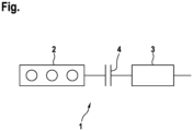
- the figure shows a hybrid drive device 1 for a motor vehicle, which has an internal combustion engine 2 and an electric machine 3.
- separating clutch 4 is arranged between the internal combustion engine 2 and the electric machine 3 and is present, for example, as a multi-plate clutch.
- the hybrid drive device 1 provides at least temporarily a drive torque for driving the motor vehicle.
- the drive torque is provided alone or at least temporarily together by the internal combustion engine 2 and the electric machine 3 in a hybrid operation.
- the internal combustion engine 2 is switched off or stopped at least temporarily during the hybrid operation of the hybrid drive device 1. In particular, it is provided to start the internal combustion engine 2 when a corresponding request quantity is present and to generate at least part of the drive torque by means of the internal combustion engine 2.
- a start attempt is carried out.
- the start attempt begins with the presence of the requirement variable or an at least partial closing of the separating clutch 4 to start the internal combustion engine 2 and ends either with a successful start of the internal combustion engine 2 or with the start attempt being aborted.
- the internal combustion engine 2 is then able to provide the drive torque at least partially independently.
- the synchronous speed is to be understood as meaning a speed of the internal combustion engine which corresponds to a current speed of the electric machine 3.
- the synchronous speed is present, there is no slip on the separating clutch 4, so that the separating clutch 4 can be completely closed and a rigid connection can be established between the internal combustion engine 2 and the electrical machine 3.
- the speed of the internal combustion engine 2 is increased from standstill towards the minimum speed.
- the internal combustion engine 2 is preferably at a standstill or has a speed that is smaller than the minimum speed.
- the separating clutch 4 is at least partially closed.
- the separating clutch 4 is set to a target clutch torque.
- the target clutch torque serves to increase the speed of the internal combustion engine 2 in the direction of the minimum speed and preferably corresponds to a predetermined starting torque, in the presence of which the speed of the internal combustion engine 2 can reach the minimum speed.
- the target clutch torque is increased by further closing of the separating clutch 4 from a first value towards a second value.
- the target clutch torque is increased until the speed of the internal combustion engine 2 has reached a minimum speed or the start attempt is aborted.
- it can be provided to gradually increase the target clutch torque in certain target clutch torque steps. The enlargement takes place in particular periodically, for example at fixed time intervals.
- the actual clutch torque actually transmitted via the separating clutch 4 is determined.
- the actual clutch torque is determined, for example, from a characteristic map of the separating clutch 4 or alternatively calculated from a speed gradient and/or a mass moment of inertia. Based on the determined actual clutch torque, a time course of the actual clutch torque can be formed. From the time course of the actual clutch torque, a characteristic value is determined which corresponds to a maximum value of the actual clutch torque that occurs after the separating clutch 4 has been at least partially closed.
- the characteristic value used is a maximum value of the actual clutch torque that occurs within a certain time window after the separating clutch 4 has been closed and not a maximum value that occurs over the entire starting attempt.
- the characteristic value is a difference from the maximum value, in particular that occurring within the time window Maximum value, and a minimum value of the actual clutch torque occurring between a minimum value of the actual clutch torque occurring before the separating clutch 4 is at least partially closed.
- a course of the speed of the internal combustion engine 2 over time is determined.
- An integral over time is determined from the time course of the speed of the internal combustion engine 2. In particular, measured values of the speed are added up over time.
- the starting attempt is only aborted if a temperature threshold value is exceeded by a temperature of the separating clutch 4.
- the threshold value is set, for example, so that it corresponds to a torque or a characteristic value at which the internal combustion engine 2 can normally be started.
- the separating clutch 4 is opened and an error entry is entered into an error memory. Closing of the separating clutch 4 is subsequently prevented as long as the error entry is entered in the error memory.
- the error entry is deleted from the error memory after a certain period of time has elapsed after the start attempt has been aborted and/or if the temperature of the separating clutch 4 falls below the temperature threshold value over the certain period of time.
- the method according to the invention prevents damage or destruction of the separating clutch 4 in the presence of a sluggish or jamming internal combustion engine 2.
Landscapes
- Engineering & Computer Science (AREA)
- Chemical & Material Sciences (AREA)
- Combustion & Propulsion (AREA)
- Transportation (AREA)
- Mechanical Engineering (AREA)
- Automation & Control Theory (AREA)
- Health & Medical Sciences (AREA)
- Biomedical Technology (AREA)
- General Health & Medical Sciences (AREA)
- Hydraulic Clutches, Magnetic Clutches, Fluid Clutches, And Fluid Joints (AREA)
- Hybrid Electric Vehicles (AREA)
Description
- Die Erfindung betrifft ein Verfahren zum Betreiben einer Hybridantriebseinrichtung für ein Kraftfahrzeug, die eine Brennkraftmaschine und eine elektrische Maschine aufweist, wobei während eines Startversuchs der Brennkraftmaschine eine zwischen der Brennkraftmaschine und der elektrischen Maschine antriebstechnisch angeordnete Trennkupplung durch zumindest teilweises Schließen auf ein Sollkupplungsmoment eingestellt wird. Die Erfindung betrifft weiterhin eine Hybridantriebseinrichtung für ein Kraftfahrzeug.
- Aus dem Stand der Technik ist beispielsweise die Druckschrift
EP 2 689 157 B1 bekannt. Diese betrifft eine Sicherheitskupplung für ein Kraftfahrzeug zur Übertragung eines Antriebsmoments zwischen einer Maschinenwelle, einer elektrischen Maschine und einer wenigstens ein Rad eines Fahrzeugs antreibenden Radantriebswelle. Im störungsfreien Normalbetrieb erfolgt über eine lösbare Formschlusskupplung eine Drehmomentübertragung zwischen der Maschinenwelle und der Radantriebswelle. Bei Auftreten eines einen Grenzwert übersteigenden Drehmoments löst die lösbare Formschlusskupplung aus, sodass eine elastische Kupplungseinrichtung die Drehmomentübertragung wenigstens kurzzeitig übernimmt. - Die Druckschrift
US 2014/0129066 A1 beschreibt eine Steuervorrichtung für ein Hybridfahrzeug, das einen Motor und einen Elektromotor, die jeweils als Antriebsquelle dienen, und eine Kupplung zum selektiven Verbinden des Motors und des Elektromotors miteinander aufweist, wobei die Steuervorrichtung dazu ausgebildet ist, einen Antriebsmodus des Hybridfahrzeugs zwischen einem motorgetriebenem Betrieb, wobei wenigstens der Motor der aus dem Motor und dem Elektromotor bestehenden Antriebsquelle als die Antriebsquelle verwendet wird und die Kupplung in einem vollständig geschlossenen Zustand ist, und einem elektromotorgetriebenen Betrieb, wobei der Elektromotor als die Antriebsquelle verwendet wird und die Kupplung in einem vollständig geöffneten Zustand ist, umzuschalten, wobei die Steuervorrichtung einen kupplungstemperaturberechnenden Teil, der dazu ausgebildet ist, während des motorgetriebenen Betriebs eine bei einem nächsten Schließen der Kupplung zum Umschalten des Antriebsmodus von dem nachfolgenden elektromotorgetriebenen Betrieb zurück in den motorgetriebenen Betrieb vorliegende voraussichtliche Temperatur der Kupplung zu berechnen, und einen Umschaltsteuerteil, der dazu ausgebildet ist, den motorgetriebenen Betrieb fortzusetzen während ein Öffnen der Kupplung unterdrückt wird, wenn die von dem kupplungstemperaturberechnenden Teil berechnete voraussichtliche Temperatur der Kupplung nicht kleiner als ein bestimmter Überhitzungsgrenzwert ist, beinhaltet. - Aus dem Stand der Technik sind weiterhin die Druckschriften
JP 2015 074299 A JP 2010 083426 A - Es ist Aufgabe der Erfindung, ein Verfahren zum Betreiben einer Hybridantriebseinrichtung für ein Kraftfahrzeug vorzuschlagen, welches gegenüber anderen Verfahren Vorteile aufweist, insbesondere eine Beschädigung der Trennkupplung aufgrund einer klemmenden oder schwergängigen Brennkraftmaschine während des Startversuchs vermeidet.
- Dies wird erfindungsgemäß mit dem Verfahren zum Betreiben einer Hybridantriebseinrichtung mit den Merkmalen des Anspruchs 1 erreicht. Dabei ist vorgesehen, dass während des Startversuchs ein über die Trennkupplung tatsächlich übertragenes Istkupplungsmoment sowie eine Drehzahl der Brennkraftmaschine ermittelt werden und bei einem Überschreiten eines Schwellenwerts durch einen von dem Istkupplungsmoment abhängigen Kennwert und einem während des Startversuchs durchgehenden Unterschreiten eines Grenzwerts durch ein Integral der Drehzahl über der Zeit der Startversuch abgebrochen wird.
- Die Hybridantriebseinrichtung dient dem Antreiben des Kraftfahrzeugs, insoweit also dem Bereitstellen eines auf das Antreiben des Kraftfahrzeugs gerichteten Drehmoments. Die Hybridantriebseinrichtung verfügt über die Brennkraftmaschine sowie die elektrische Maschine. Diese sind dazu vorgesehen und ausgebildet, ein von der Hybridantriebseinrichtung geliefertes Antriebsdrehmoment jeweils alleine oder zumindest zeitweise gemeinsam bereitzustellen. Das bedeutet, dass das Antriebsdrehmoment nur von der Brennkraftmaschine und ohne Verwendung der elektrischen Maschine, nur von der elektrischen Maschine und ohne Verwendung der Brennkraftmaschine oder von der Brennkraftmaschine und der elektrischen Maschine gemeinsam bereitgestellt wird.
- Eine hinreichende Versorgung mit elektrischer Energie vorausgesetzt, beispielsweise bei Vorliegen eines hinreichenden Ladestandes eines elektrischen Energiespeichers, kann die elektrische Maschine das Antriebsmoment alleine, also ohne Verwendung der Brennkraftmaschine liefern. Die Brennkraftmaschine kann zugeschaltet werden, um das Antriebsdrehmoment alleine oder durch Zusammenwirken mit der elektrischen Maschine bereitzustellen. Hierzu ist es vorgesehen, die Brennkraftmaschine mittels der elektrischen Maschine zu starten.
- Um die Brennkraftmaschine zu starten, wird der Startversuch durchgeführt. Der Startversuch beginnt bei Vorliegen einer Anforderungsgröße an die Hybridantriebseinrichtung, die den Wunsch nach einem Zuschalten der Brennkraftmaschine signalisiert. Der Startversuch endet entweder mit einem erfolgreichen Start der Brennkraftmaschine oder einem Abbruch des Startversuchs.
- Unter dem Startversuch ist ein Vorgang zu verstehen, bei welchem versucht wird, die Brennkraftmaschine derart einzustellen, dass sie nachfolgend zumindest einen Teil des Antriebsdrehmoments bereitstellen kann beziehungsweise bereitstellt. Während des Startversuchs soll die Drehzahl der Brennkraftmaschine, beispielsweise aus dem Stillstand heraus, auf eine von null verschiedene Drehzahl gebracht werden, insbesondere auf eine Drehzahl, welche zumindest einer Mindestdrehzahl, einer Leerlaufdrehzahl und/oder eine Synchrondrehzahl der Brennkraftmaschine entspricht.
- Die Mindestdrehzahl ist diejenige Drehzahl, ab welcher die Brennkraftmaschine selbsttätig, also ohne einen externen Antrieb wie einen Starter, ihre Drehzahl weiter erhöhen kann. Die Leerlaufdrehzahl ist diejenige Drehzahl, bei welcher die Brennkraftmaschine betrieben wird, wenn sie kein Antriebsdrehmoment bereitstellt, sondern lediglich ihre Drehzahl halten soll. Die Leerlaufdrehzahl ist bevorzugt für eine leisen und/oder vibrationsarmen Lauf der Brennkraftmaschine gewählt. Die Leerlaufdrehzahl ist vorzugsweise größer als die Mindestdrehzahl.
- Unter der Synchrondrehzahl ist eine Drehzahl der Brennkraftmaschine zu verstehen, die einer momentan vorliegenden Drehzahl der elektrischen Maschine entspricht. Bei Vorliegen der Synchrondrehzahl liegt an der Trennkupplung kein Schlupf vor, so dass die Trennkupplung vollständig geschlossen und eine starre Verbindung zwischen der Brennkraftmaschine und der elektrischen Maschine hergestellt werden kann. Die Synchrondrehzahl ist vorzugsweise größer als die Mindestdrehzahl. Sie kann der Leerlaufdrehzahl entsprechen oder größer sein als diese.
- Vorzugsweise endet der Startversuch bei dem Vorliegen der Synchrondrehzahl und mit dem vollständigen Schließen der Trennkupplung.
- Während des Startversuchs wird die Trennkupplung zumindest teilweise geschlossen. Hierbei wird die Trennkupplung auf das Sollkupplungsmoment eingestellt. Das Sollkupplungsmoment dient dem Erhöhen der Drehzahl der Brennkraftmaschine in Richtung der Mindestdrehzahl und entspricht vorzugsweise einem Anschleppmoment, bei dessen Vorliegen die Drehzahl der Brennkraftmaschine die Mindestdrehzahl, die Leerlaufdrehzahl und/oder die Synchrondrehzahl erreichen kann.
- Bei Vorliegen eines Fehlers oder Defekts der Brennkraftmaschine kann eine Situation eintreten, in der die Drehzahl der Brennkraftmaschine die Mindestdrehzahl nicht erreicht oder die Mindestdrehzahl nur kurzfristig erreicht wird und die Drehzahl nachfolgend unter die Mindestdrehzahl fällt.
- Der Fehler beziehungsweise Defekt liegt insbesondere in Form eines mechanischen Defekts vor, zum Beispiel in Form eines Klemmens der Abtriebswelle und/oder anderer drehenden Teile der Brennkraftmaschine. Beispielsweise kann die Fehlfunktion durch eine unzureichende Schmierung der Brennkraftmaschine verursacht werden, was sich in einer Schwergängigkeit der Brennkraftmaschine oder einem sogenannten Kolbenfresser äußert. In jedem Fall handelt es sich bei hierbei um einen Fehler, der das zum Erreichen der Mindestdrehzahl erforderliche Anschleppmoment gegenüber einer fehlerfreien Brennkraftmaschine vergrößert oder ein Erreichen der Mindestdrehzahl unmöglich macht. Somit kann der Startversuch nicht erfolgreich abgeschlossen werden oder, falls die Brennkraftmaschine trotz Vorliegen der fehlerhaften Brennkraftmaschine die Mindestdrehzahl kurzzeitig erreicht, wird er abgeschlossen ohne die Brennkraftmaschine erfolgreich zu starten.
- Dies führt dazu, dass die Trennkupplung während des Startversuchs über einen längeren Zeitraum mit dem Sollkupplungsmoment beaufschlagt wird oder, im Falle des kurzfristigen Erreichens der Mindestdrehzahl durch die Drehzahl der Brennkraftmaschine, fälschlicherweise vollständig geschlossen wird. Hierdurch kann eine Beschädigung der Trennkupplung erfolgen, beispielsweise aufgrund einer hohen thermischen und/oder mechanischen Belastung.
- Zur Vermeidung der Beschädigung der Trennkupplung sieht das erfindungsgemäße Verfahren den Abbruch des Startversuchs vor. Dabei soll der Startversuch abgebrochen werden, falls die Brennkraftmaschine nicht erfolgreich startet und somit die fehlerhafte Brennkraftmaschine vorliegt.
- Das Erkennen des Fehlers beziehungsweise Defekts der Brennkraftmaschine ist nicht trivial. Um die fehlerhafte Brennkraftmaschine zu erkennen, sieht das erfindungsgemäße Verfahren daher wenigstens zwei Bedingungen vor, bei deren Vorliegen der Startversuch abgebrochen wird.
- Die erste Bedingung für den Abbruch des Startversuchs ist erfüllt, wenn der von dem Istkupplungsmoment abhängige Kennwert den Schwellenwert überschreitet. Es wird insoweit darauf geprüft, ob das von der Trennkupplung tatsächlich übertragene Istkupplungsmoment zumindest einem zum Starten einer fehlerfreien Brennkraftmaschine notwendigen Drehmoment entspricht. In anderen Worten wird durch die erste Bedingung eine ordnungsgemäße Funktion der Trennkupplung festgestellt.
- Es könnte nun vorgesehen sein, als zweite Bedingung ein erfolgreiches Starten der Brennkraftmaschine zu erkennen, wenn die Drehzahl der Brennkraftmaschine die Mindestdrehzahl und/oder die Leerlaufdrehzahl erreicht beziehungsweise diese überschreitet. Das Vorliegen der fehlerhaften Brennkraftmaschine kann allerdings dazu führen, dass die Drehzahl der Brennkraftmaschine während des Startversuchs zwar kurzzeitig die Mindestdrehzahl und/oder die Leerlaufdrehzahl erreicht, aufgrund der Fehlfunktion allerdings anschließend wieder unter diese Werte fällt.
- Stattdessen sieht die Erfindung vor, die zweite Bedingung auf das Integral der Drehzahl zu richten. Die zweite Bedingung für den Abbruch des Startversuchs ist erfüllt, wenn das Integral der Drehzahl über der Zeit während des Startversuchs durchgehend den Grenzwert unterschreitet. Schlussendlich wird also auf einen Fehler der Brennkraftmaschine geschlossen, wenn die Drehzahl der Brennkraftmaschine, insbesondere trotz ausreichend großem Istkupplungsmoment, nicht die Mindestdrehzahl erreicht oder die Mindestdrehzahl lediglich kurzzeitig überschreitet. In anderen Wort wird durch die zweite Bedingung festgestellt, ob die Drehbewegung der Brennkraftmaschine in für ihren Start hinreichendem Maß vorliegt.
- Um die erste Bedingung zu überprüfen sieht das erfindungsgemäße Verfahren vor, während des Startversuchs das über die Trennkupplung tatsächlich übertragene Istkupplungsmoment zu ermitteln. Das von der Trennkupplung tatsächlich übertragene Istkupplungsmoment kann beispielsweise mittels eines Kennfelds der Trennkupplung ermittelt werden, insbesondere in Verbindung mit einem Istwert einer Stellgröße der Trennkupplung, beispielsweise einem Anpressdruck. Hierzu kann beispielsweise ein Istwert des Anpressdrucks ermittelt und mit einem aus dem Sollkupplungsmoment ermittelten Sollwert des Anpressdrucks verglichen werden. Zusätzlich oder alternativ kann das Istkupplungsmoment mittels eines Modells berechnet werden, welches beispielsweise auf einer Eingangsseite und einer Ausgangsseite der Trennkupplung vorliegende Drehzahlen sowie Trägheitsmomente der entsprechenden drehenden Komponenten berücksichtig.
- Das ermittelte Istkupplungsmoment liegt in Form eines Verlauf des Istkupplungsmoments über der Zeit vor. Insofern kann zu jedem Zeitpunkt während des Startversuchs ein entsprechender momentaner Wert des Istkupplungsmoments ermittelt werden, der dem tatsächlich übertragenen Istkupplungsmoment entspricht oder dieses zumindest näherungsweise abbildet. Aus dem Istkupplungsmoment oder dem zeitlichen Verlauf des Istkupplungsmoments wird der Kennwert gebildet, dessen Überschreiten des Schwellenwerts die erste Bedingung für den Startabbruch darstellt. Der Kennwert dient dem Erkennen der Funktionsfähigkeit der Trennkupplung. Überschreitet der von dem Istkupplungsmoment abhängige Kennwert den Schwellenwert, so wird von einer Funktionsfähigkeit der Trennkupplung ausgegangen.
- Beispielsweise entspricht der Kennwert dem Istkupplungsmoment. Vorzugsweise handelt es sich jedoch bei dem Kennwert um eine aus dem Verlauf des Istkupplungsmoments ermittelte Größe, die das bei oder unmittelbar nach dem zumindest teilweisen Schließen übertragene Istkupplungsmoment abbildet beziehungsweise näherungsweise diesem entspricht. Der Kennwert kann beispielsweise ein Maximalwert des Istkupplungsmoments, eine Differenz zweier Werte oder ein Gradient des Istkupplungsmoments, jeweils innerhalb eines definierten Zeitfensters sein.
- Um die zweite Bedingung für Abbruch des Startversuchs zu überprüfen, wird zusätzlich zu dem tatsächlich übertragenen Istkupplungsmoment die Drehzahl der Brennkraftmaschine ermittelt. Die Drehzahl der Brennkraftmaschine liegt vorzugsweise ebenfalls in Form eines Verlaufs über der Zeit vor. Aus dem Verlauf der Drehzahl über der Zeit wird das Integral der Drehzahl ermittelt. Insbesondere werden Messwerte der Drehzahl über der Zeit aufsummiert. Gemäß dem erfindungsgemäßen Verfahrens ist es für einen erfolgreichen Start der Brennkraftmaschine nicht ausreichend, die Drehzahl lediglich kurzzeitig auf die Mindestdrehzahl zu erhöhen, vielmehr muss die Drehzahl über einen ausreichend langen Zeitraum von null verschieden sein, um den Grenzwert durch das Integral der Drehzahl zu überschreiten. Durch eine Berücksichtigung des Integrals der Drehzahl erfolgt somit eine zuverlässige Erkennung der Drehbewegung der Brennkraftmaschine.
- Um beide Bedingungen zu erfüllen und in Folge den Startversuch abzubrechen, muss einerseits der von dem Istkupplungsmoment abhängige Kennwert den Schwellenwert überschreiten und andererseits das Integral der Drehzahl während des Startversuchs den Grenzwert durchgehend unterschreiten. Eine derartige Vorgehensweise stellt sicher, dass der Fehler beziehungsweise der Defekt der Brennkraftmaschine während des Startversuchs erkannt wird. Somit wird eine Beschädigung der Trennkupplung zuverlässig vermieden.
- Eine Weiterbildung der Erfindung sieht vor, dass der Startversuch nur bei einem zusätzlichen Überschreiten eines Temperaturschwellenwerts durch eine Temperatur der Trennkupplung abgebrochen wird. Die Temperatur der Trennkupplung wird somit zur Prüfung einer dritten Bedingung für den Abbruch des Startversuchs herangezogen, die zusätzlich zu der ersten Bedingung und der zweiten Bedingung erfüllt sein muss. Dabei ist vorgesehen, den Startversuch abzubrechen, falls die Temperatur der Trennkupplung den Temperaturschwellenwert überschreitet. In anderen Worten wird der Startversuch fortgesetzt, solange die Temperatur der Trennkupplung unterhalb des Temperaturschwellenwerts liegt. Hierdurch wird der Startversuch abgebrochen, bevor die Temperatur der Trennkupplung einen kritischen Wert erreichen kann und eine Beschädigung vermieden.
- Eine Weiterbildung der Erfindung sieht vor, dass zum Abbrechen des Startversuchs die Trennkupplung geöffnet und ein Fehlereintrag in einen Fehlerspeicher eingetragen wird, wobei nachfolgend ein Schließen der Trennkupplung verhindert wird, solange der Fehlereintrag in dem Fehlerspeicher eingetragen ist. Da das Starten der Brennkraftmaschine mittels der elektrischen Maschine erfolgt, wozu die Trennkupplung zumindest teilweise geschlossen wird, wird der Startversuch durch ein Öffnen der Trennkupplung abgebrochen, insbesondere wird die Trennkupplung zum Abbrechen des Startversuchs vollständig geöffnet.
- Gleichzeitig erfolgt der Eintrag des Fehlereintrags in dem Fehlerspeicher, der beispielsweise in einem Steuergerät der Brennkraftmaschine und/oder der Hybridantriebseinrichtung vorliegt. Nach dem Abbrechen des Startversuchs wird von dem Vorliegen der fehlerhaften Brennkraftmaschine ausgegangen. Daher wird nachfolgend das Schließen der Trennkupplung verhindert, solange der Fehlereintrag in dem Fehlerspeicher eingetragen ist. Hierdurch wird ein wiederholtes Schließen der Trennkupplung und die damit verbundene mögliche Beschädigung der Trennkupplung verhindert. Anstelle des Eintragens des Fehlereintrags kann ein Festhalten eines Fehlerzustands erfolgen. Dabei wird der Fehlerzustand bei dem Abbrechen des Startversuchs als aktiv markiert. Somit liegt nach dem Abbrechen des Startversuchs ein als aktiv markierter Fehlerzustand vor. Während des Vorliegens des aktiven Fehlerzustands steht die Brennkraftmaschine nicht zum Bereitstellen des Antriebsdrehmoments zu Verfügung. Der aktive Fehlerzustand kann mit einer Durchführung entsprechender Gegenmaßnahmen verbunden sein, die einen zuverlässigen Betrieb der Hybridantriebseinrichtung ohne eine Verwendung der Brennkraftmaschine ermöglichen.
- Eine Weiterbildung der Erfindung sieht vor, dass nach Ablauf eines bestimmten Zeitraums nach dem Abbrechen des Startversuchs der Fehlereintrag aus dem Fehlerspeicher gelöscht wird. Wie bereits vorstehend erläutert, werden das Schließen der Trennkupplung und somit ein erneuter Startversuch der Brennkraftmaschine verhindert, solange der Fehlereintrag in dem Fehlerspeicher eingetragen ist. Ein erneuter Startversuch ist erst nach einem Löschen des Fehlereintrags aus dem Fehlerspeicher möglich.
- Es ist nun vorgesehen, den Fehlereintrag nach Ablauf des bestimmten Zeitraums nach dem Abbrechen des Startversuchs zu löschen. Somit wird das Schließen der Trennkupplung nach dem Abbrechen des Startversuchs nicht dauerhaft verhindert, sondern lediglich über den bestimmten Zeitraum. Die Länge des bestimmten Zeitraum kann an weitere Bedingungen geknüpft sein, beispielsweise an ein zwischenzeitlich erfolgtes Abschalten der Hybridantriebseinrichtung. Hierdurch wird verhindert, dass nach dem Abbrechen des Startversuchs und dem Ablauf des bestimmten Zeitraums kein erneuter Startversuch mehr möglich ist. Erfolgte bei dem Abbrechen des Startversuchs das Festhalten des Fehlerzustandes, so wird dieser nach Ablauf des bestimmten Zeitraums als passiv markiert. Während des Vorliegens des passiven Fehlerzustands werden die vorstehend genannten Gegenmaßnahmen nicht mehr durchgeführt, sodass ein zuverlässiger Betrieb der Hybridantriebseinrichtung unter Verwendung der Brennkraftmaschine ermöglicht wird.
- Eine Weiterbildung der Erfindung sieht vor, dass nur bei einem Unterschreiten des Temperaturschwellenwerts durch die Temperatur der Trennkupplung über den bestimmten Zeitraum der Fehlereintrag aus dem Fehlerspeicher gelöscht wird. Wie vorstehend erläutert, kann es vorgesehen sein, dass der Startversuch nur bei dem zusätzlichen Überschreiten des Temperaturschwellenwerts durch die Temperatur der Trennkupplung abgebrochen wird. Dementsprechend wird der Fehlereintrag nur dann aus dem Fehlerspeicher gelöscht, wenn die Temperatur der Trennkupplung den Temperaturschwellenwert unterschreitet. Erfolgte bei dem Abbrechen des Startversuchs das Festhalten des Fehlerzustandes, so wird dieser - wie vorstehend erläutert - als passiv markiert.
- Hierdurch wird sichergestellt, dass ein erneuter Startversuch verhindert wird, solange die Temperatur der Trennkupplung oberhalb des Temperaturschwellenwerts vorliegt. In anderen Worten, wird nach dem Abbruch des Startversuch ein erneuter Startversuch verhindert, solange sich die Temperatur der Trennkupplung in einem kritischen Temperaturbereich befindet und somit eine Beschädigung der Trennkupplung aufgrund der fehlerhaften Brennkraftmaschine wahrscheinlicher wird.
- Eine Weiterbildung der Erfindung sieht vor, dass als Kennwert ein nach dem zumindest teilweisen Schließen der Trennkupplung auftretender Maximalwert des Istkupplungsmoments verwendet wird. Wie bereits vorstehend erläutert, stellt der Kennwert eine von dem Istkupplungsmoment abhängige Größe dar. Es ist vorgesehen, den Maximalwert des Istkupplungsmoments als Kennwert zu verwenden, der innerhalb eines Zeitfensters auftritt, das mit dem teilweisen Schließen der Trennkupplung beginnt und zu einem vorbestimmten Zeitpunkt nach dem teilweisen Schließens der Trennkupplung endet. In anderen Worten wird als Kennwert nicht der während des gesamten Startversuchs auftretende Maximalwert des Istkupplungsmoments herangezogen, sondern lediglich der innerhalb des vordefinierten Zeitfensters auftretende Maximalwert des Istkupplungsmoments. Da der Kennwert der Überprüfung der ordnungsgemäßen Funktion der Trennkupplung dient, ist es vorteilhaft diese Überprüfung innerhalb des Zeitfensters durchzuführen. Alternativ kann als Kennwert ein innerhalb des Zeitfensters auftretender Gradient des Istkupplungsmoments verwendet werden. Diese Vorgehensweise ermöglicht eine Überprüfung, ob die Trennkupplung eine für deren ordnungsgemäße Funktion ausreichend schnelle Reaktionsgeschwindigkeit zeigt.
- Eine Weiterbildung der Erfindung sieht vor, dass als Kennwert eine Differenz zwischen dem Maximalwert und einem vor dem teilweisen Schließen der Trennkupplung auftretenden Minimalwert des Istkupplungsmoments verwendet wird. Da das Ermitteln des Istkupplungsmoments mit absoluten und relativen Fehlern behaftet sein kann, sieht die Erfindung vor, zusätzlich zu dem Maximalwert den Minimalwert zu bestimmen und als Kennwert eine Differenz aus diesen Werten zu verwenden. Auf diese Weise werden bei dem Ermitteln des tatsächlich übertragenen Istkupplungsmoments Fehler ausgeglichen und die Verlässlichkeit der Bestimmung des Kennwerts verbessert.
- Eine Weiterbildung der Erfindung sieht vor, dass das Sollkupplungsmoment bei dem Schließen auf einen ersten Wert eingestellt und während des Startversuchs in Richtung eines zweiten Werts vergrößert wird, bis die Drehzahl der Brennkraftmaschine eine Mindestdrehzahl erreicht hat. Während des Startversuchs wird das Sollkupplungsmoment zunächst auf einen ersten Wert eingestellt, insbesondere auf einen vorgegebenen ersten Wert. Anschließend wird das Sollkupplungsmoment erhöht, bis hin zu einem vollständigen Schlie-βen der Trennkupplung und dem Vorliegen einer starren Verbindung zwischen der Brennkraftmaschine und der elektrischen Maschine, vorausgesetzt es erfolgt kein Abbruch des Startversuchs aufgrund der zuvor erläuterten Bedingungen.
- In anderen Worten wird das Sollkupplungsmoment in Richtung des zweiten Werts vergrößert, solange die Drehzahl der Brennkraftmaschine die Mindestdrehzahl nicht erreicht und kein Abbruch des Startversuchs erfolgt. Das Erhöhen kann kontinuierlich oder in diskreten Schritten erfolgen. Hierdurch wird sichergestellt, dass ein zum Starten der Brennkraftmaschine ausreichendes Istkupplungsmoment vorliegt und bei Vorliegen einer fehlerfreien Brennkraftmaschine diese zuverlässig startet.
- Eine Weiterbildung des Verfahrens sieht vor, dass das Vergrößern des Sollkupplungsmoments in bestimmten Sollkupplungsmomentenschritten erfolgt, wobei der Startversuch abgebrochen wird, falls der zweite Wert durch das Sollkupplungsmoment erreicht oder überschritten wird. Bei dem zweiten Wert des Sollkupplungsmoments handelt es sich insbesondere um ein von der Trennkupplung maximal übertragbares Sollkupplungsmoment.
- Somit wird das Sollkupplungsmoment nicht kontinuierlich sondern stufenweise vergrößert. Insbesondere wird der Startversuch abgebrochen, wenn das Sollkupplungsmoment den zweiten Wert erreicht, ohne dass die Drehzahl der Brennkraftmaschine die Mindestdrehzahl erreicht. Hierdurch wird sichergestellt, dass einerseits versucht wird, die Brennkraftmaschine durch das Erhöhen des Sollkupplungsmoments erfolgreich zu starten, andererseits wird eine Beschädigung der Trennkupplung vermieden, da der Startversuch abgebrochen wird, bevor das von der Trennkupplung maximal übertragbares Sollkupplungsmoment überschritten wird.
- Die Erfindung betrifft weiterhin eine Hybridantriebseinrichtung für ein Kraftfahrzeug, insbesondere zur Durchführung des Verfahrens gemäß den Ausführungen im Rahmen dieser Beschreibung, wobei die Hybridantriebseinrichtung eine Brennkraftmaschine und eine elektrische Maschine aufweist und dazu ausgebildet ist, während eines Startversuchs der Brennkraftmaschine eine zwischen der Brennkraftmaschine und der elektrischen Maschine antriebstechnisch angeordnete Trennkupplung durch zumindest teilweises Schließen auf ein Sollkupplungsmoment einzustellen. Dabei ist vorgesehen, dass die Hybridantriebseinrichtung weiter dazu ausgebildet ist, während des Startversuchs der Brennkraftmaschine ein über die Trennkupplung tatsächlich übertragenes Istkupplungsmoment sowie eine Drehzahl der Brennkraftmaschine zu ermitteln, wobei bei einem Überschreiten eines Schwellenwerts durch einen von dem Istkupplungsmoment abhängigen Kennwert und einem während des Startversuchs durchgehenden Unterschreiten eines Grenzwerts durch ein Integral der Drehzahl über der Zeit der Startversuch abgebrochen wird.
- Auf die Vorteile einer derartigen Ausgestaltung der Hybridantriebseinrichtung sowie einer derartigen Vorgehensweise wurde bereits hingewiesen. Sowohl die Hybridantriebseinrichtung als auch das Verfahren zu ihrem Betreiben können gemäß den Ausführungen im Rahmen dieser Beschreibung weitergebildet sein, sodass insoweit auf diese verwiesen wird.
- Die Erfindung wird nachfolgend anhand der in der Zeichnung dargestellten Ausführungsbeispiele näher erläutert, ohne dass eine Beschränkung der Erfindung erfolgt. Dabei zeigt die einzige
- Figur
- eine schematische Darstellung einer Hybridantriebseinrichtung zur Durchführung des Verfahrens gemäß dieser Beschreibung.
- Die Figur zeigt eine Hybridantriebseinrichtung 1 für ein Kraftfahrzeug, die eine Brennkraftmaschine 2 und eine elektrische Maschine 3 aufweist. Eine Trennkupplung 4 ist antriebstechnisch zwischen der Brennkraftmaschine 2 und der elektrischen Maschine 3 angeordnet und liegt beispielsweise als Lamellenkupplung vor. Die Hybridantriebseinrichtung 1 stellt zumindest zeitweise ein Antriebsdrehmoment zum Antreiben des Kraftfahrzeugs bereit. Das Antriebsdrehmoment wird jeweils allein oder in einem Hybridbetrieb zumindest zeitweise gemeinsam von der Brennkraftmaschine 2 und der elektrischen Maschine 3 bereit gestellt.
- Die Brennkraftmaschine 2 wird während des Hybridbetriebs der Hybridantriebseinrichtung 1 zumindest zeitweise abgestellt beziehungsweise gestoppt. Insbesondere ist es vorgesehen, die Brennkraftmaschine 2 bei Vorliegen einer entsprechenden Anforderungsgröße zu starten und zumindest einen Teil des Antriebsdrehmoments mittels der Brennkraftmaschine 2 zu erzeugen.
- Zum Starten der Brennkraftmaschine 2 wird ein Startversuch durchgeführt. Der Startversuch beginnt mit dem Vorliegen der Anforderungsgröße oder einem zumindest teilweisen Schließen der Trennkupplung 4 zum Starten der Brennkraftmaschine 2 und endet entweder mit einem erfolgreichen Start der Brennkraftmaschine 2 oder einem Abbruch des Startversuchs. Im Falle eines erfolgreichen Starts ist die Brennkraftmaschine 2 anschließend in der Lage das Antriebsdrehmoment zumindest teilweise selbstständig bereitzustellen.
- Bei dem erfolgreichen Start der Brennkraftmaschine 2 erreicht diese eine Mindestdrehzahl, eine Leerlaufdrehzahl oder eine Synchrondrehzahl. Unter der Synchrondrehzahl ist eine Drehzahl der Brennkraftmaschine zu verstehen, die einer momentan vorliegenden Drehzahl der elektrischen Maschine 3 entspricht. Bei Vorliegen der Synchrondrehzahl liegt an der Trennkupplung 4 kein Schlupf vor, so dass die Trennkupplung 4 vollständig geschlossen und eine starre Verbindung zwischen der Brennkraftmaschine 2 und der elektrischen Maschine 3 hergestellt werden kann.
- Bei dem Startversuch wird die Drehzahl der Brennkraftmaschine 2 aus dem Stillstand heraus in Richtung der Mindestdrehzahl erhöht. Zu Beginn des Startversuchs liegt die Brennkraftmaschine 2 vorzugsweise in einem Stillstand vor oder weist eine Drehzahl auf, die kleiner ist als die Mindestdrehzahl.
- Während des Startversuchs wird die Trennkupplung 4 zumindest teilweise geschlossen. Hierbei wird die Trennkupplung 4 auf ein Sollkupplungsmoment eingestellt. Das Sollkupplungsmoment dient dem Erhöhen der Drehzahl der Brennkraftmaschine 2 in Richtung der Mindestdrehzahl und entspricht vorzugsweise einem vorgegebenen Anschleppmoment, bei dessen Vorliegen die Drehzahl der Brennkraftmaschine 2 die Mindestdrehzahl erreichen kann.
- Das Sollkupplungsmoment wird durch ein weiteres Schließen der Trennkupplung 4 ausgehend von einem ersten Wert in Richtung eines zweiten Werts vergrößert. Das Vergrößern des Sollkupplungsmoments erfolgt bis die Drehzahl der Brennkraftmaschine 2 eine Mindestdrehzahl erreicht hat oder der Startversuch abgebrochen wird. Insbesondere kann es vorgesehen sein, das Sollkupplungsmoment in bestimmten Sollkupplungsmomentenschritten stufenweise zu vergrößern. Das Vergrößern erfolgt insbesondere periodisch, beispielsweise in festgelegten Zeitabständen.
- Während des Startversuchs wird das über die Trennkupplung 4 tatsächlich übertragene Istkupplungsmoment ermittelt. Das Istkupplungsmoment wird beispielsweise aus einem Kennfeld der Trennkupplung 4 ermittelt oder alternativ aus einem Drehzahlgradienten und/oder einem Massenträgheitsmoment berechnet. Anhand des ermittelten Istkupplungsmoment kann ein zeitlicher Verlauf des Istkupplungsmoment gebildet werden. Aus dem zeitlichen Verlauf des Istkupplungsmoments wird ein Kennwert ermittelt, der einem nach dem zumindest teilweisen Schließen der Trennkupplung 4 auftretenden Maximalwert des Istkupplungsmoments entspricht.
- Vorzugsweise wird als Kennwert ein innerhalb eines bestimmten Zeitfensters nach dem Schließen der Trennkupplung 4 auftretender Maximalwert des Istkupplungsmoments und nicht ein über den gesamten Startversuch auftretender Maximalwert verwendet. Alternativ wird als Kennwert eine Differenz aus dem Maximalwert, insbesondere dem innerhalb des Zeitfensters auftretenden Maximalwerts, und einem zwischen einem vor dem zumindest teilweisen Schließen der Trennkupplung 4 auftretender Minimalwert des Istkupplungsmoments verwendet.
- Zusätzlich wird ein Verlauf der Drehzahl der Brennkraftmaschine 2 über der Zeit ermittelt. Aus dem zeitlichen Verlauf der Drehzahl der Brennkraftmaschine 2 wird ein Integral über der Zeit ermittelt. Insbesondere werden hierzu Messwerte der Drehzahl über der Zeit aufsummiert.
- Es ist vorgesehen, den Startversuch abzubrechen, wenn der Kennwert einen Schwellenwert überschreitet und das Integral der Drehzahl während des Startversuchs durchgehend einen Grenzwert unterschreitet. Zusätzlich kann vorgesehen sein, dass der Startversuch nur bei einem zusätzlichen Überschreiten eines Temperaturschwellenwerts durch eine Temperatur der Trennkupplung 4 abgebrochen wird. Der Schwellenwert wird beispielsweise so festgelegt, dass er einem Drehmoment oder einem Kennwert entspricht, bei welchem die Brennkraftmaschine 2 normalerweise gestartet werden kann.
- Zum Abbrechen des Startversuchs wird die Trennkupplung 4 geöffnet und ein Fehlereintrag in einem Fehlerspeicher eingetragen. Nachfolgend wird ein Schließen der Trennkupplung 4 verhindert, solange der Fehlereintrag in dem Fehlerspeicher eingetragen ist. Der Fehlereintrag wird nach Ablauf eines bestimmten Zeitraums nach dem Abbrechen des Startversuchs aus dem Fehlerspeicher gelöscht und/oder wenn die Temperatur der Trennkupplung 4 den Temperaturschwellenwert über den bestimmten Zeitraum unterschreitet.
- Durch das erfindungsgemäße Verfahren wird bei Vorliegen einer schwergängigen oder klemmenden Brennkraftmaschine 2 eine Beschädigung oder Zerstörung der Trennkupplung 4 vermieden.
-
- 1
- Hybridantriebseinrichtung
- 2
- Brennkraftmaschine
- 3
- Elektrische Maschine
- 4
- Trennkupplung
Claims (10)
- Verfahren zum Betreiben einer Hybridantriebseinrichtung (1) für ein Kraftfahrzeug, die eine Brennkraftmaschine (2) und eine elektrische Maschine (3) aufweist, wobei während eines Startversuchs der Brennkraftmaschine (2) eine zwischen der Brennkraftmaschine (2) und der elektrischen Maschine (3) angeordnete Trennkupplung (4) durch zumindest teilweises Schließen auf ein Sollkupplungsmoment eingestellt wird, dadurch gekennzeichnet, dass während des Startversuchs ein über die Trennkupplung (4) tatsächlich übertragenes Istkupplungsmoment sowie eine Drehzahl der Brennkraftmaschine (2) ermittelt werden und bei einem Überschreiten eines Schwellenwerts durch einen von dem Istkupplungsmoment abhängigen Kennwert und einem während des Startversuchs durchgehenden Unterschreiten eines Grenzwerts durch ein Integral der Drehzahl über der Zeit der Startversuch abgebrochen wird.
- Verfahren nach Anspruch 1, dadurch gekennzeichnet, dass der Startversuch nur bei einem zusätzlichen Überschreiten eines Temperaturschwellenwerts durch eine Temperatur der Trennkupplung (4) abgebrochen wird.
- Verfahren nach einem der vorhergehenden Ansprüche, dadurch gekennzeichnet, dass zum Abbrechen des Startversuchs die Trennkupplung (4) geöffnet und ein Fehlereintrag an dem Fehlerspeicher eingetragen wird, wobei nachfolgend ein Schließen der Trennkupplung (4) verhindert wird, solange der Fehlereintrag in dem Fehlerspeicher eingetragen ist.
- Verfahren nach einem der vorhergehenden Ansprüche, dadurch gekennzeichnet, dass nach Ablauf eines bestimmten Zeitraums nach dem Abbrechen des Startversuchs der Fehlereintrag aus dem Fehlerspeicher gelöscht wird.
- Verfahren nach einem der vorhergehenden Ansprüche, dadurch gekennzeichnet, dass nur bei einem Unterschreiten des Temperaturschwellenwerts durch die Temperatur der Trennkupplung (4) über den bestimmten Zeitraum der Fehlereintrag aus dem Fehlerspeicher gelöscht wird.
- Verfahren nach einem der vorhergehenden Ansprüche, dadurch gekennzeichnet, dass als Kennwert ein nach dem zumindest teilweisen Schließen der Trennkupplung (4) auftretender Maximalwert des Istkupplungsmoments verwendet wird.
- Verfahren nach einem der vorhergehenden Ansprüche, dadurch gekennzeichnet, dass als Kennwert eine Differenz aus dem Maximalwert und einem vor dem teilweisen Schließen der Trennkupplung (4) auftretender Minimalwert des Istkupplungsmoments verwendet wird.
- Verfahren nach einem der vorhergehenden Ansprüche, dadurch gekennzeichnet, dass das Sollkupplungsmoment bei dem Schließen auf einen ersten Wert eingestellt und während des Startversuchs in Richtung eines zweiten Werts vergrößert wird, bis die Drehzahl der Brennkraftmaschine (2) eine Mindestdrehzahl erreicht hat.
- Verfahren nach einem der vorhergehenden Ansprüche, dadurch gekennzeichnet, dass das Vergrößern des Sollkupplungsmoments in bestimmten Sollkupplungsmomentenschritten erfolgt, wobei der Startversuch abgebrochen wird, falls der zweite Wert durch das Sollkupplungsmoment erreicht oder überschritten wird.
- Hybridantriebseinrichtung (1) für ein Kraftfahrzeug, insbesondere zur Durchführung des Verfahrens nach einem oder mehreren der vorhergehenden Ansprüche, wobei die Hybridantriebseinrichtung (1) eine Brennkraftmaschine (2) und eine elektrische Maschine (3) aufweist und dazu ausgebildet ist, während eines Startversuchs der Brennkraftmaschine (2) eine zwischen der Brennkraftmaschine (2) und der elektrischen Maschine (3) antriebstechnisch angeordnete Trennkupplung (4) durch zumindest teilweises Schließen auf ein Sollkupplungsmoment einzustellen, dadurch gekennzeichnet, dass die Hybridantriebseinrichtung (1) weiter dazu ausgebildet ist, während des Startversuchs der Brennkraftmaschine (2) ein über die Trennkupplung (4) tatsächlich übertragenes Istkupplungsmoment sowie eine Drehzahl der Brennkraftmaschine (2) zu ermitteln, wobei bei einem Überschreiten eines Schwellenwerts durch einen von dem Istkupplungsmoment abhängigen Kennwert und einem während des Startversuchs durchgehenden Unterschreitens eines Grenzwerts durch ein Integral der Drehzahl über der Zeit der Startversuch abgebrochen wird.
Applications Claiming Priority (2)
| Application Number | Priority Date | Filing Date | Title |
|---|---|---|---|
| DE102020105592.7A DE102020105592A1 (de) | 2020-03-03 | 2020-03-03 | Verfahren zum Betreiben einer Hybridantriebseinrichtung für ein Kraftfahrzeug sowie entsprechende Hybridantriebseinrichtung |
| PCT/EP2021/053930 WO2021175597A1 (de) | 2020-03-03 | 2021-02-18 | Verfahren zum betreiben einer hybridantriebseinrichtung für ein kraftfahrzeug sowie entsprechende hybridantriebseinrichtung |
Publications (2)
| Publication Number | Publication Date |
|---|---|
| EP4114699A1 EP4114699A1 (de) | 2023-01-11 |
| EP4114699B1 true EP4114699B1 (de) | 2023-11-01 |
Family
ID=74673191
Family Applications (1)
| Application Number | Title | Priority Date | Filing Date |
|---|---|---|---|
| EP21707188.5A Active EP4114699B1 (de) | 2020-03-03 | 2021-02-18 | Verfahren zum betreiben einer hybridantriebseinrichtung für ein kraftfahrzeug sowie entsprechende hybridantriebseinrichtung |
Country Status (5)
| Country | Link |
|---|---|
| US (1) | US11745725B2 (de) |
| EP (1) | EP4114699B1 (de) |
| CN (1) | CN114929534B (de) |
| DE (1) | DE102020105592A1 (de) |
| WO (1) | WO2021175597A1 (de) |
Families Citing this family (1)
| Publication number | Priority date | Publication date | Assignee | Title |
|---|---|---|---|---|
| DE102020205395A1 (de) * | 2020-04-29 | 2021-11-04 | Bayerische Motoren Werke Aktiengesellschaft | Verfahren zum Betrieb eines Kraftfahrzeug Antriebsstranges, sowie elektronische Steuereinheit zur Durchführung des Verfahrens |
Family Cites Families (16)
| Publication number | Priority date | Publication date | Assignee | Title |
|---|---|---|---|---|
| DE3540719A1 (de) | 1984-12-01 | 1986-06-05 | Zahnradfabrik Friedrichshafen Ag, 7990 Friedrichshafen | Einrichtung zum ueberlastschutz fuer reibkupplungen |
| JP2004204747A (ja) * | 2002-12-25 | 2004-07-22 | Mazda Motor Corp | エンジンの自動停止・始動制御装置 |
| JP2006123642A (ja) * | 2004-10-27 | 2006-05-18 | Aisin Aw Co Ltd | ハイブリッド車用駆動装置、その制御方法及び制御装置 |
| EP2232050B1 (de) | 2007-12-11 | 2019-06-12 | GE Hybrid Technologies, LLC | Verfahren und vorrichtung zum starten eines verbrennungsmotors |
| DE102008040830A1 (de) * | 2008-07-29 | 2010-02-04 | Robert Bosch Gmbh | Verfahren und Vorrichtung einer Start-Stopp-Steuerung für eine Brennkraftmaschine |
| JP5158201B2 (ja) * | 2008-07-30 | 2013-03-06 | アイシン・エィ・ダブリュ株式会社 | 駆動装置および車両 |
| JP5212001B2 (ja) | 2008-10-02 | 2013-06-19 | 日産自動車株式会社 | ハイブリッド車両の制御装置及び制御方法 |
| DE102011015024B3 (de) | 2011-03-25 | 2012-04-19 | Audi Ag | Sicherheitskupplung für ein Kraftfahrzeug |
| WO2013137279A1 (ja) * | 2012-03-16 | 2013-09-19 | 日産自動車株式会社 | ハイブリッド駆動電気自動車の駆動制御装置及び駆動制御方法 |
| US9026295B2 (en) * | 2012-11-01 | 2015-05-05 | Toyota Jidosha Kabushiki Kaisha | Control apparatus for hybrid vehicle |
| US9238458B2 (en) | 2013-03-15 | 2016-01-19 | Ford Global Technologies, Llc | Hybrid-electric vehicle engine starting method and system |
| JP6194735B2 (ja) | 2013-10-08 | 2017-09-13 | 日産自動車株式会社 | ハイブリッド車両の制御装置 |
| US9669824B2 (en) * | 2015-11-02 | 2017-06-06 | Ford Global Technologies, Llc | Methods and system for starting an engine |
| CN105644561B (zh) * | 2015-12-25 | 2018-04-03 | 潍柴动力股份有限公司 | 一种amt车辆起步控制方法及系统 |
| US11473544B2 (en) * | 2021-01-05 | 2022-10-18 | Ford Global Technologies, Llc | Methods and system for starting an engine |
| US11995923B2 (en) * | 2021-03-25 | 2024-05-28 | Ford Global Technologies, Llc | Vehicle powertrain control system |
-
2020
- 2020-03-03 DE DE102020105592.7A patent/DE102020105592A1/de not_active Withdrawn
-
2021
- 2021-02-18 WO PCT/EP2021/053930 patent/WO2021175597A1/de not_active Ceased
- 2021-02-18 EP EP21707188.5A patent/EP4114699B1/de active Active
- 2021-02-18 CN CN202180008027.3A patent/CN114929534B/zh active Active
- 2021-02-18 US US17/783,779 patent/US11745725B2/en active Active
Also Published As
| Publication number | Publication date |
|---|---|
| US11745725B2 (en) | 2023-09-05 |
| CN114929534A (zh) | 2022-08-19 |
| WO2021175597A1 (de) | 2021-09-10 |
| CN114929534B (zh) | 2025-08-15 |
| DE102020105592A1 (de) | 2021-09-09 |
| US20230011692A1 (en) | 2023-01-12 |
| EP4114699A1 (de) | 2023-01-11 |
Similar Documents
| Publication | Publication Date | Title |
|---|---|---|
| DE102005021250B4 (de) | Verfahren für den Unterspannungsschutz während des Motoranlassens | |
| AT511612B1 (de) | Verfahren zum starten einer brennkraftmaschine | |
| DE102022001489B3 (de) | Verfahren zum Betrieb eines elektrischen Antriebssystems für ein Kraftfahrzeug | |
| EP3206925B1 (de) | Verfahren zum betreiben einer hybridantriebseinrichtung sowie entsprechende hybridantriebseinrichtung | |
| EP2331378B1 (de) | Verfahren zum diagnostizieren eines fehlerstatus einer antriebsvorrichtung sowie diagnosevorrichtung und antriebssystem | |
| DE102008000904A1 (de) | Verfahren und Vorrichtung zur Steuerung einer elektrischen Maschine eines Hybridantriebs bei erhöhter Verfügbarkeit | |
| WO2017202419A1 (de) | Verfahren zum betrieb eines antriebsstrangs eines hybridfahrzeugs und antriebsstrang eines hybridfahrzeugs | |
| WO2011076485A1 (de) | Verfahren und vorrichtung zur bestimmung eines solldrehmomentes zur ansteuerung einer elektrischen maschine eines kraftfahrzeuges | |
| DE102008042887A1 (de) | Verfahren zur Verfügbarkeitserhöhung bei Hybridfahrzeugen | |
| EP4114699B1 (de) | Verfahren zum betreiben einer hybridantriebseinrichtung für ein kraftfahrzeug sowie entsprechende hybridantriebseinrichtung | |
| DE102011054480B4 (de) | Verfahren und Diagnosevorrichtung zum Diagnostizieren eines Betriebszustands einer Trennkupplung | |
| EP3298306B1 (de) | Verfahren zum betreiben einer elektrisch ansteuerbaren förderpumpe in einem hydraulikkreis | |
| EP3263382B1 (de) | Verfahren zum betreiben einer antriebseinrichtung sowie entsprechende antriebseinrichtung | |
| WO2013152846A1 (de) | Verfahren zum betreiben einer hybridantriebsvorrichtung | |
| DE102008044016B4 (de) | Verfahren zum Erfassen eines sich einstellenden Drehmomentes für einen Hybridantrieb | |
| DE102023207175B3 (de) | Verfahren zur Bestimmung eines Synchronisierungspunktes eines Koppelvorgangs einer Klauenkupplung | |
| WO2008052622A1 (de) | Kraftfahrzeugantrieb | |
| DE102012224214A1 (de) | Steuerungseinrichtung und Verfahren zum Betreiben eines Hydrauliksystems eines Hybridfahrzeugs | |
| WO2017032368A1 (de) | Verfahren zur plausibilisierung eines drehmomentverlaufs zur ermittlung eines tastpunktes einer hybridtrennkupplung im antriebsstrang eines hybridfahrzeuges | |
| DE102014224850B4 (de) | Verfahren zur Erkennung von sicherheitskritischen Betätigungen einer Trennkupplung in einem Hybridmodul eines Antriebsstranges eines Kraftfahrzeuges | |
| DE102016215125A1 (de) | Verfahren zur Steuerung einer Notfalleinrichtung und Klappensteuergerät | |
| DE102017210613B4 (de) | Starteinrichtung für einen Verbrennungsmotor | |
| DE102020202063A1 (de) | Verfahren und Steuergerät zum Betreiben eines Hybridfahrzeugs | |
| DE102018218401A1 (de) | Verfahren und Steuerungssystem zum Betreiben eines Kraftfahrzeugs | |
| DE102008042891A1 (de) | Verfahren zur automatischen Tastpunktadaption |
Legal Events
| Date | Code | Title | Description |
|---|---|---|---|
| STAA | Information on the status of an ep patent application or granted ep patent |
Free format text: STATUS: UNKNOWN |
|
| STAA | Information on the status of an ep patent application or granted ep patent |
Free format text: STATUS: THE INTERNATIONAL PUBLICATION HAS BEEN MADE |
|
| PUAI | Public reference made under article 153(3) epc to a published international application that has entered the european phase |
Free format text: ORIGINAL CODE: 0009012 |
|
| STAA | Information on the status of an ep patent application or granted ep patent |
Free format text: STATUS: REQUEST FOR EXAMINATION WAS MADE |
|
| 17P | Request for examination filed |
Effective date: 20221004 |
|
| AK | Designated contracting states |
Kind code of ref document: A1 Designated state(s): AL AT BE BG CH CY CZ DE DK EE ES FI FR GB GR HR HU IE IS IT LI LT LU LV MC MK MT NL NO PL PT RO RS SE SI SK SM TR |
|
| GRAP | Despatch of communication of intention to grant a patent |
Free format text: ORIGINAL CODE: EPIDOSNIGR1 |
|
| STAA | Information on the status of an ep patent application or granted ep patent |
Free format text: STATUS: GRANT OF PATENT IS INTENDED |
|
| DAV | Request for validation of the european patent (deleted) | ||
| DAX | Request for extension of the european patent (deleted) | ||
| INTG | Intention to grant announced |
Effective date: 20230508 |
|
| P01 | Opt-out of the competence of the unified patent court (upc) registered |
Effective date: 20230529 |
|
| GRAS | Grant fee paid |
Free format text: ORIGINAL CODE: EPIDOSNIGR3 |
|
| GRAA | (expected) grant |
Free format text: ORIGINAL CODE: 0009210 |
|
| STAA | Information on the status of an ep patent application or granted ep patent |
Free format text: STATUS: THE PATENT HAS BEEN GRANTED |
|
| RAP3 | Party data changed (applicant data changed or rights of an application transferred) |
Owner name: AUDI AG |
|
| AK | Designated contracting states |
Kind code of ref document: B1 Designated state(s): AL AT BE BG CH CY CZ DE DK EE ES FI FR GB GR HR HU IE IS IT LI LT LU LV MC MK MT NL NO PL PT RO RS SE SI SK SM TR |
|
| REG | Reference to a national code |
Ref country code: GB Ref legal event code: FG4D Free format text: NOT ENGLISH |
|
| REG | Reference to a national code |
Ref country code: CH Ref legal event code: EP |
|
| REG | Reference to a national code |
Ref country code: DE Ref legal event code: R096 Ref document number: 502021001864 Country of ref document: DE |
|
| REG | Reference to a national code |
Ref country code: IE Ref legal event code: FG4D Free format text: LANGUAGE OF EP DOCUMENT: GERMAN |
|
| REG | Reference to a national code |
Ref country code: LT Ref legal event code: MG9D |
|
| REG | Reference to a national code |
Ref country code: NL Ref legal event code: MP Effective date: 20231101 |
|
| PG25 | Lapsed in a contracting state [announced via postgrant information from national office to epo] |
Ref country code: GR Free format text: LAPSE BECAUSE OF FAILURE TO SUBMIT A TRANSLATION OF THE DESCRIPTION OR TO PAY THE FEE WITHIN THE PRESCRIBED TIME-LIMIT Effective date: 20240202 |
|
| PG25 | Lapsed in a contracting state [announced via postgrant information from national office to epo] |
Ref country code: IS Free format text: LAPSE BECAUSE OF FAILURE TO SUBMIT A TRANSLATION OF THE DESCRIPTION OR TO PAY THE FEE WITHIN THE PRESCRIBED TIME-LIMIT Effective date: 20240301 |
|
| PG25 | Lapsed in a contracting state [announced via postgrant information from national office to epo] |
Ref country code: LT Free format text: LAPSE BECAUSE OF FAILURE TO SUBMIT A TRANSLATION OF THE DESCRIPTION OR TO PAY THE FEE WITHIN THE PRESCRIBED TIME-LIMIT Effective date: 20231101 |
|
| PG25 | Lapsed in a contracting state [announced via postgrant information from national office to epo] |
Ref country code: NL Free format text: LAPSE BECAUSE OF FAILURE TO SUBMIT A TRANSLATION OF THE DESCRIPTION OR TO PAY THE FEE WITHIN THE PRESCRIBED TIME-LIMIT Effective date: 20231101 |
|
| PG25 | Lapsed in a contracting state [announced via postgrant information from national office to epo] |
Ref country code: ES Free format text: LAPSE BECAUSE OF FAILURE TO SUBMIT A TRANSLATION OF THE DESCRIPTION OR TO PAY THE FEE WITHIN THE PRESCRIBED TIME-LIMIT Effective date: 20231101 |
|
| PG25 | Lapsed in a contracting state [announced via postgrant information from national office to epo] |
Ref country code: NL Free format text: LAPSE BECAUSE OF FAILURE TO SUBMIT A TRANSLATION OF THE DESCRIPTION OR TO PAY THE FEE WITHIN THE PRESCRIBED TIME-LIMIT Effective date: 20231101 Ref country code: LT Free format text: LAPSE BECAUSE OF FAILURE TO SUBMIT A TRANSLATION OF THE DESCRIPTION OR TO PAY THE FEE WITHIN THE PRESCRIBED TIME-LIMIT Effective date: 20231101 Ref country code: IS Free format text: LAPSE BECAUSE OF FAILURE TO SUBMIT A TRANSLATION OF THE DESCRIPTION OR TO PAY THE FEE WITHIN THE PRESCRIBED TIME-LIMIT Effective date: 20240301 Ref country code: GR Free format text: LAPSE BECAUSE OF FAILURE TO SUBMIT A TRANSLATION OF THE DESCRIPTION OR TO PAY THE FEE WITHIN THE PRESCRIBED TIME-LIMIT Effective date: 20240202 Ref country code: ES Free format text: LAPSE BECAUSE OF FAILURE TO SUBMIT A TRANSLATION OF THE DESCRIPTION OR TO PAY THE FEE WITHIN THE PRESCRIBED TIME-LIMIT Effective date: 20231101 Ref country code: BG Free format text: LAPSE BECAUSE OF FAILURE TO SUBMIT A TRANSLATION OF THE DESCRIPTION OR TO PAY THE FEE WITHIN THE PRESCRIBED TIME-LIMIT Effective date: 20240201 Ref country code: PT Free format text: LAPSE BECAUSE OF FAILURE TO SUBMIT A TRANSLATION OF THE DESCRIPTION OR TO PAY THE FEE WITHIN THE PRESCRIBED TIME-LIMIT Effective date: 20240301 |
|
| PG25 | Lapsed in a contracting state [announced via postgrant information from national office to epo] |
Ref country code: SE Free format text: LAPSE BECAUSE OF FAILURE TO SUBMIT A TRANSLATION OF THE DESCRIPTION OR TO PAY THE FEE WITHIN THE PRESCRIBED TIME-LIMIT Effective date: 20231101 Ref country code: RS Free format text: LAPSE BECAUSE OF FAILURE TO SUBMIT A TRANSLATION OF THE DESCRIPTION OR TO PAY THE FEE WITHIN THE PRESCRIBED TIME-LIMIT Effective date: 20231101 Ref country code: PL Free format text: LAPSE BECAUSE OF FAILURE TO SUBMIT A TRANSLATION OF THE DESCRIPTION OR TO PAY THE FEE WITHIN THE PRESCRIBED TIME-LIMIT Effective date: 20231101 Ref country code: NO Free format text: LAPSE BECAUSE OF FAILURE TO SUBMIT A TRANSLATION OF THE DESCRIPTION OR TO PAY THE FEE WITHIN THE PRESCRIBED TIME-LIMIT Effective date: 20240201 Ref country code: LV Free format text: LAPSE BECAUSE OF FAILURE TO SUBMIT A TRANSLATION OF THE DESCRIPTION OR TO PAY THE FEE WITHIN THE PRESCRIBED TIME-LIMIT Effective date: 20231101 Ref country code: HR Free format text: LAPSE BECAUSE OF FAILURE TO SUBMIT A TRANSLATION OF THE DESCRIPTION OR TO PAY THE FEE WITHIN THE PRESCRIBED TIME-LIMIT Effective date: 20231101 |
|
| PG25 | Lapsed in a contracting state [announced via postgrant information from national office to epo] |
Ref country code: DK Free format text: LAPSE BECAUSE OF FAILURE TO SUBMIT A TRANSLATION OF THE DESCRIPTION OR TO PAY THE FEE WITHIN THE PRESCRIBED TIME-LIMIT Effective date: 20231101 |
|
| PG25 | Lapsed in a contracting state [announced via postgrant information from national office to epo] |
Ref country code: CZ Free format text: LAPSE BECAUSE OF FAILURE TO SUBMIT A TRANSLATION OF THE DESCRIPTION OR TO PAY THE FEE WITHIN THE PRESCRIBED TIME-LIMIT Effective date: 20231101 |
|
| PG25 | Lapsed in a contracting state [announced via postgrant information from national office to epo] |
Ref country code: SK Free format text: LAPSE BECAUSE OF FAILURE TO SUBMIT A TRANSLATION OF THE DESCRIPTION OR TO PAY THE FEE WITHIN THE PRESCRIBED TIME-LIMIT Effective date: 20231101 |
|
| PG25 | Lapsed in a contracting state [announced via postgrant information from national office to epo] |
Ref country code: SM Free format text: LAPSE BECAUSE OF FAILURE TO SUBMIT A TRANSLATION OF THE DESCRIPTION OR TO PAY THE FEE WITHIN THE PRESCRIBED TIME-LIMIT Effective date: 20231101 Ref country code: SK Free format text: LAPSE BECAUSE OF FAILURE TO SUBMIT A TRANSLATION OF THE DESCRIPTION OR TO PAY THE FEE WITHIN THE PRESCRIBED TIME-LIMIT Effective date: 20231101 Ref country code: IT Free format text: LAPSE BECAUSE OF FAILURE TO SUBMIT A TRANSLATION OF THE DESCRIPTION OR TO PAY THE FEE WITHIN THE PRESCRIBED TIME-LIMIT Effective date: 20231101 Ref country code: EE Free format text: LAPSE BECAUSE OF FAILURE TO SUBMIT A TRANSLATION OF THE DESCRIPTION OR TO PAY THE FEE WITHIN THE PRESCRIBED TIME-LIMIT Effective date: 20231101 Ref country code: DK Free format text: LAPSE BECAUSE OF FAILURE TO SUBMIT A TRANSLATION OF THE DESCRIPTION OR TO PAY THE FEE WITHIN THE PRESCRIBED TIME-LIMIT Effective date: 20231101 Ref country code: CZ Free format text: LAPSE BECAUSE OF FAILURE TO SUBMIT A TRANSLATION OF THE DESCRIPTION OR TO PAY THE FEE WITHIN THE PRESCRIBED TIME-LIMIT Effective date: 20231101 |
|
| REG | Reference to a national code |
Ref country code: DE Ref legal event code: R097 Ref document number: 502021001864 Country of ref document: DE |
|
| PLBE | No opposition filed within time limit |
Free format text: ORIGINAL CODE: 0009261 |
|
| STAA | Information on the status of an ep patent application or granted ep patent |
Free format text: STATUS: NO OPPOSITION FILED WITHIN TIME LIMIT |
|
| PG25 | Lapsed in a contracting state [announced via postgrant information from national office to epo] |
Ref country code: MC Free format text: LAPSE BECAUSE OF FAILURE TO SUBMIT A TRANSLATION OF THE DESCRIPTION OR TO PAY THE FEE WITHIN THE PRESCRIBED TIME-LIMIT Effective date: 20231101 |
|
| REG | Reference to a national code |
Ref country code: CH Ref legal event code: PL |
|
| 26N | No opposition filed |
Effective date: 20240802 |
|
| PG25 | Lapsed in a contracting state [announced via postgrant information from national office to epo] |
Ref country code: LU Free format text: LAPSE BECAUSE OF NON-PAYMENT OF DUE FEES Effective date: 20240218 |
|
| PG25 | Lapsed in a contracting state [announced via postgrant information from national office to epo] |
Ref country code: CH Free format text: LAPSE BECAUSE OF NON-PAYMENT OF DUE FEES Effective date: 20240229 |
|
| PG25 | Lapsed in a contracting state [announced via postgrant information from national office to epo] |
Ref country code: SI Free format text: LAPSE BECAUSE OF FAILURE TO SUBMIT A TRANSLATION OF THE DESCRIPTION OR TO PAY THE FEE WITHIN THE PRESCRIBED TIME-LIMIT Effective date: 20231101 |
|
| PG25 | Lapsed in a contracting state [announced via postgrant information from national office to epo] |
Ref country code: SI Free format text: LAPSE BECAUSE OF FAILURE TO SUBMIT A TRANSLATION OF THE DESCRIPTION OR TO PAY THE FEE WITHIN THE PRESCRIBED TIME-LIMIT Effective date: 20231101 Ref country code: LU Free format text: LAPSE BECAUSE OF NON-PAYMENT OF DUE FEES Effective date: 20240218 Ref country code: CH Free format text: LAPSE BECAUSE OF NON-PAYMENT OF DUE FEES Effective date: 20240229 |
|
| REG | Reference to a national code |
Ref country code: BE Ref legal event code: MM Effective date: 20240229 |
|
| PG25 | Lapsed in a contracting state [announced via postgrant information from national office to epo] |
Ref country code: BE Free format text: LAPSE BECAUSE OF NON-PAYMENT OF DUE FEES Effective date: 20240229 |
|
| PG25 | Lapsed in a contracting state [announced via postgrant information from national office to epo] |
Ref country code: IE Free format text: LAPSE BECAUSE OF NON-PAYMENT OF DUE FEES Effective date: 20240218 |
|
| PG25 | Lapsed in a contracting state [announced via postgrant information from national office to epo] |
Ref country code: IE Free format text: LAPSE BECAUSE OF NON-PAYMENT OF DUE FEES Effective date: 20240218 Ref country code: BE Free format text: LAPSE BECAUSE OF NON-PAYMENT OF DUE FEES Effective date: 20240229 |
|
| PGFP | Annual fee paid to national office [announced via postgrant information from national office to epo] |
Ref country code: AT Payment date: 20250417 Year of fee payment: 5 |
|
| PG25 | Lapsed in a contracting state [announced via postgrant information from national office to epo] |
Ref country code: RO Free format text: LAPSE BECAUSE OF FAILURE TO SUBMIT A TRANSLATION OF THE DESCRIPTION OR TO PAY THE FEE WITHIN THE PRESCRIBED TIME-LIMIT Effective date: 20231101 |
|
| PG25 | Lapsed in a contracting state [announced via postgrant information from national office to epo] |
Ref country code: CY Free format text: LAPSE BECAUSE OF FAILURE TO SUBMIT A TRANSLATION OF THE DESCRIPTION OR TO PAY THE FEE WITHIN THE PRESCRIBED TIME-LIMIT; INVALID AB INITIO Effective date: 20210218 |
|
| PG25 | Lapsed in a contracting state [announced via postgrant information from national office to epo] |
Ref country code: HU Free format text: LAPSE BECAUSE OF FAILURE TO SUBMIT A TRANSLATION OF THE DESCRIPTION OR TO PAY THE FEE WITHIN THE PRESCRIBED TIME-LIMIT; INVALID AB INITIO Effective date: 20210218 |
|
| PG25 | Lapsed in a contracting state [announced via postgrant information from national office to epo] |
Ref country code: FI Free format text: LAPSE BECAUSE OF FAILURE TO SUBMIT A TRANSLATION OF THE DESCRIPTION OR TO PAY THE FEE WITHIN THE PRESCRIBED TIME-LIMIT Effective date: 20231101 |
|
| PG25 | Lapsed in a contracting state [announced via postgrant information from national office to epo] |
Ref country code: TR Free format text: LAPSE BECAUSE OF FAILURE TO SUBMIT A TRANSLATION OF THE DESCRIPTION OR TO PAY THE FEE WITHIN THE PRESCRIBED TIME-LIMIT Effective date: 20231101 |
|
| PGFP | Annual fee paid to national office [announced via postgrant information from national office to epo] |
Ref country code: GB Payment date: 20260219 Year of fee payment: 6 |
|
| PGFP | Annual fee paid to national office [announced via postgrant information from national office to epo] |
Ref country code: DE Payment date: 20260228 Year of fee payment: 6 |
|
| PGFP | Annual fee paid to national office [announced via postgrant information from national office to epo] |
Ref country code: FR Payment date: 20260223 Year of fee payment: 6 |