EP4114698B1 - Fluidventil, ventilanordnung und bremsanlage - Google Patents
Fluidventil, ventilanordnung und bremsanlage Download PDFInfo
- Publication number
- EP4114698B1 EP4114698B1 EP21710444.7A EP21710444A EP4114698B1 EP 4114698 B1 EP4114698 B1 EP 4114698B1 EP 21710444 A EP21710444 A EP 21710444A EP 4114698 B1 EP4114698 B1 EP 4114698B1
- Authority
- EP
- European Patent Office
- Prior art keywords
- pressure
- switching element
- lip
- fluid valve
- sealing lip
- Prior art date
- Legal status (The legal status is an assumption and is not a legal conclusion. Google has not performed a legal analysis and makes no representation as to the accuracy of the status listed.)
- Active
Links
Images




Classifications
-
- B—PERFORMING OPERATIONS; TRANSPORTING
- B60—VEHICLES IN GENERAL
- B60T—VEHICLE BRAKE CONTROL SYSTEMS OR PARTS THEREOF; BRAKE CONTROL SYSTEMS OR PARTS THEREOF, IN GENERAL; ARRANGEMENT OF BRAKING ELEMENTS ON VEHICLES IN GENERAL; PORTABLE DEVICES FOR PREVENTING UNWANTED MOVEMENT OF VEHICLES; VEHICLE MODIFICATIONS TO FACILITATE COOLING OF BRAKES
- B60T15/00—Construction arrangement, or operation of valves incorporated in power brake systems and not covered by groups B60T11/00 or B60T13/00
- B60T15/02—Application and release valves
- B60T15/18—Triple or other relay valves which allow step-wise application or release and which are actuated by brake-pipe pressure variation to connect brake cylinders or equivalent to compressed air or vacuum source or atmosphere
- B60T15/20—Triple or other relay valves which allow step-wise application or release and which are actuated by brake-pipe pressure variation to connect brake cylinders or equivalent to compressed air or vacuum source or atmosphere controlled by two fluid pressures
-
- B—PERFORMING OPERATIONS; TRANSPORTING
- B60—VEHICLES IN GENERAL
- B60T—VEHICLE BRAKE CONTROL SYSTEMS OR PARTS THEREOF; BRAKE CONTROL SYSTEMS OR PARTS THEREOF, IN GENERAL; ARRANGEMENT OF BRAKING ELEMENTS ON VEHICLES IN GENERAL; PORTABLE DEVICES FOR PREVENTING UNWANTED MOVEMENT OF VEHICLES; VEHICLE MODIFICATIONS TO FACILITATE COOLING OF BRAKES
- B60T15/00—Construction arrangement, or operation of valves incorporated in power brake systems and not covered by groups B60T11/00 or B60T13/00
- B60T15/02—Application and release valves
-
- F—MECHANICAL ENGINEERING; LIGHTING; HEATING; WEAPONS; BLASTING
- F16—ENGINEERING ELEMENTS AND UNITS; GENERAL MEASURES FOR PRODUCING AND MAINTAINING EFFECTIVE FUNCTIONING OF MACHINES OR INSTALLATIONS; THERMAL INSULATION IN GENERAL
- F16J—PISTONS; CYLINDERS; SEALINGS
- F16J15/00—Sealings
- F16J15/16—Sealings between relatively-moving surfaces
- F16J15/32—Sealings between relatively-moving surfaces with elastic sealings, e.g. O-rings
- F16J15/3204—Sealings between relatively-moving surfaces with elastic sealings, e.g. O-rings with at least one lip
Definitions
- the invention relates to a fluid valve according to the preamble of claim 1.
- the invention also relates to a pneumatic valve arrangement and a pneumatic brake system for a vehicle, in particular for a trailer vehicle.
- Fluid valves are understood here to mean valves for all flowing media, in particular pneumatic valves, preferably for use in pneumatic brake systems.
- Pneumatic brake systems in trailers with a parking release valve can fulfill various safety functions. For example, a so-called park/save function can be provided, which is intended to avoid a dangerous situation in connection with incorrect operation.
- park/save function can be provided, which is intended to avoid a dangerous situation in connection with incorrect operation.
- the parking release valve should be in the park position. Even if the parking release valve is in its travel position, the trailer vehicle that is not yet coupled is braked because existing spring brakes are then vented and effective.
- the Park/Save function means that the spring brakes are not yet ventilated and released under these conditions. Rather, at least it has to The service brake must be applied once.
- the brake pressure applied acts as control pressure to cancel the Park/Save function.
- the park/save function and a possible constructive solution are shown in the DE 10 2016 005 625 A1 , especially in connection with the Fig. 6 until 11.
- the park/save function can be integrated into a so-called parking release valve or be part of a valve arrangement with which a parking release function is implemented.
- the Fig. 7 the DE 10 2016 005 625 A1 shows a pneumatic circuit diagram Fig. 8 up to 11 a highly integrated parking release valve, matching the pneumatic circuit diagram.
- the park/save function results from the interaction of a control slide 105 with a locking slide 104 and associated seals and flow channels.
- the parking release valve can be designed as a simple slide valve, while the park/save function can be implemented using a valve specifically designed for this purpose.
- EP 3 477 168 A1 discloses a valve with a pressure inlet and a pressure outlet and with a switching element that is movable along an axis between a first stop and a second stop. Furthermore, the valve has a membrane that acts as a check element. The valve has an open position in which the switching element rests against the first stop. The valve also has a blocking position in which the switching element rests against the second stop. The switching element can rest against the membrane in the blocked position: If a pressure at the pressure outlet is higher than a pressure at the pressure inlet, the membrane is pressed against the switching element; However, if the pressure at the pressure inlet is higher than the pressure at the pressure outlet, the membrane lifts off the switching element (non-return function).
- the object of the present invention is to create a fluid valve which is suitable as a parking safety valve or for implementing the park/save function.
- the fluid valve should be as reliable, smooth-running and maintenance-free as possible.
- the fluid valve according to the invention has the features of claim 1.
- the fluid valve is then provided between a pressure inlet and a pressure outlet with a lip seal having a sealing lip, wherein a position of the sealing lip can be changed to change a passage cross section.
- the sealing lip can assume different positions, so that a passage cross section between the pressure inlet and pressure outlet can be adjusted.
- the sealing lip is not moved as a whole. Rather, only part of the sealing lip is angled or bent relative to the lip seal.
- the sealing lip can be made of a correspondingly elastic material, as can the lip seal as a whole.
- the fluid valve is intended in particular for pneumatic brake systems in trailer vehicles, but can also be used for other applications related to flowing media.
- the frictional forces in the fluid valve shown with a switchable lip seal are relatively low.
- the sealing lip rests against a sealing surface in a blocking position and is at a distance from the sealing surface in a passage position.
- the passage cross section is defined by the distance and given geometric conditions.
- the sealing lip has an internal stress which acts on the sealing lip to reduce the passage cross section. This means that the sealing lip strives to assume the position with the smallest passage cross-section without being influenced by other components.
- the sealing lip then lies against a sealing surface.
- the sealing lip extends at an acute angle to the sealing surface and is arranged to be self-retaining, that is, if the pressure at the pressure inlet is greater than at the pressure outlet, the sealing lip is pressed against the sealing surface by the pressure difference and thus maintains the above-mentioned blocking position.
- the position of the sealing lip can be changed by pressing a switching element.
- the switching element indirectly changes the passage cross section.
- the pressure of the switching element preferably counteracts the internal tension of the sealing lip.
- the switching element is used to change the position of the sealing lip and can itself be controlled, for example, by a fluid. By moving the switching element, the pressure of the switching element can be exerted and the sealing lip can be switched, so that either the connection from the pressure inlet to the pressure outlet can be opened and closed or simply the passage cross section can be changed. By changing the passage cross section, the sealing lip can be switched continuously.
- the Actuation of the sealing lip by the switching element can occur indirectly or directly. For example, an additional component can be provided between the switching element and the sealing lip. The switching element then only acts indirectly on the sealing lip.
- the sealing lip is supported on the switching element in a blocking position. In the locked position, the sealing lip then lies on the one hand against the sealing surface and on the other hand is supported by the switching element, preferably by an edge or collar of the switching element.
- the switching element can rest on the sealing lip, wherein the sealing lip can be acted upon by the switching element to increase the passage cross section.
- the switching element acts more strongly on the sealing lip in a pass position than in the blocking position.
- the lip seal can have a lip holder on which the sealing lip is held.
- An angle of the sealing lip to the lip holder can be changed by mechanical pressure from the switching element. The change in angle can also result from deformation of the sealing lip.
- the switching element can be mushroom-shaped with a trunk and roof.
- the lip holder can be cup-shaped with a cup opening and a base, the base having a base opening.
- the trunk can extend into the cup opening and into the bottom opening.
- the roof can then rest against the lip seal in the passage position.
- the lip seal or the roof can be provided with a sealing bead. In this way, the roof seals the cup opening when the lip seal is in the open position.
- the roof can have a circumferential collar which is inclined towards the bottom of the lip holder, whereby the sealing lip extends circumferentially outwards from an edge next to the cup opening, and the sealing lip is acted upon by the collar of the roof in the passage position.
- the collar preferably acts on the sealing lip during the entire actuation of the sealing lip, in particular also in the blocking position.
- the switching element can be acted upon by a return spring in the direction of relieving the sealing lip.
- the return spring acts against the switching element and must also be overcome by pressure at the control connection or pressure output, as well as the internal tension of the sealing lip.
- the fluid valve may have a housing.
- the switching element is movable in the housing against the action of the return spring, and that a widening of the switching element with a minimized passage cross section rests on a shoulder of the housing due to the action of the return spring.
- the return spring, widening and shoulder define an end position of the switching element that can be moved in the housing of the fluid valve.
- the lip holder can be arranged in a fixed position in the housing.
- the lip holder like the sealing lip, is then part of the lip seal.
- the lip holder is intended to be fixed, while the sealing lip is movable or flexible.
- the sealing lip changes its shape, position and/or angle relative to the lip holder.
- the housing can have a cylindrical interior.
- the switching element can be movable in the axial direction.
- the lip seal can also be held in the interior.
- the switching element and lip seal are preferably adapted to the cylindrical shape of the interior.
- the sealing lip when the passage cross-section is closed, can divide the interior into an output volume connected to the pressure outlet and an input volume connected to the pressure inlet. If the passage cross-section is not closed, the output volume and input volume are connected to one another via the passage cross-section.
- a relief volume connected to a relief outlet can be formed between the lip seal and the switching element, the relief volume and the output volume being connected to one another via a flow channel in the switching element at least in a blocking position of the sealing lip.
- a connection from the relief volume to the flow channel in the passage position of the sealing lip can be closed by a seal between the lip seal and the switching element.
- the seal separates the relief volume from the flow channel and the associated output volume. In this way, the flow channel is securely closed in the passage position.
- a control piston which can be moved between an initial position and an actuation position can be present in a housing of the fluid valve, which can be moved out of its initial position by pressure on a control connection and in the actuation position acts on a switching element for actuating the sealing lip.
- the control piston moves into the actuating position, the sealing lip moves into the open position.
- control piston can have a control volume connected to the control connection from one to the pressure output separate the connected output volume.
- control piston is preferably provided with a circumferential seal. By increasing pressure in the control volume, the control piston can be moved to reduce the output volume.
- At least two switching positions can be provided, namely the blocking position and the open position.
- at least four connections can be provided, namely the pressure inlet, the pressure outlet, a relief outlet and a control connection.
- a switching element can be movable in the housing.
- the movable switching element can be provided to selectively open or close the passage cross section from the pressure inlet to the pressure outlet depending on the pressure at the pressure outlet and at the control connection.
- the switching element can have a holding function, the holding function being designed such that the passage cross section is open when the pressure at the control port is above a first limit value, and remains open even when the pressure at the control port falls below the first limit value again but there is a pressure above a second limit value at the pressure outlet.
- the fluid valve for example as a parking safety valve in a pneumatic brake system.
- the limit values mentioned are preferably between 1 and 3.5 bar, in particular between 2 and 3 bar.
- the first and second limits can be identical, but can also differ.
- a pneumatic valve arrangement with a parking release valve has a fluid valve according to one of claims 1 to 18 to solve the problem.
- the fluid valve preferably has the function of a parking safety valve.
- the valve arrangement is preferably intended for a brake system of a vehicle, in particular for a brake system of a trailer vehicle.
- the pressure inlet of the fluid valve can be connected to a supply connection of the valve arrangement that is under supply pressure, with the pressure outlet of the fluid valve being connected to it a connection of the parking release valve is connected and a control connection of the fluid valve is connected to a control connection of the valve arrangement.
- the control connection of the valve arrangement can preferably be acted upon with brake pressure from the pneumatic brake system.
- the supply connection of the valve arrangement receives the supply pressure from a “supply” coupling head, while the brake pressure is supplied via a “brake” coupling head.
- the invention also relates to a pneumatic brake system for a trailer vehicle, with a fluid valve according to one of claims 1 to 19 or with a valve arrangement according to one of claims 20 and 21.
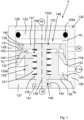
- the fluid valve F has a cylindrical housing 125 with a top wall 126, a bottom wall 127 and a circumferential side wall 128.
- the control connection 4 F is provided in the area of the upper wall 126.
- a control piston 122 is axially movable below the upper wall 126 and is provided with a circumferential seal 128a.
- a lip seal 129 is arranged on the bottom wall 127, which has a cup-shaped lip holder 129a with a cup opening 148 and with a radially directed bottom collar 130 on the bottom side.
- a collar-like sealing lip 132 extends outwards from an upper edge 131 of the cup-shaped lip holder 129a.
- the sealing lip 132 is directed obliquely downwards and lies in the in Fig. 1 shown first switching position/locking position with a lower sealing edge 133 on a sealing surface 134 of the housing 125.
- the sealing surface 134 is provided here on the inside of the side wall 128.
- the housing 125 has the pressure inlet 1-1 F on the side and the pressure outlet 2 F axially above it.
- the sealing surface 134 lies between the pressure inlet 1-1 F and the pressure outlet 2 F.
- the bottom collar 130 is additionally provided with a sealing bead 135 on the radial outside, which rests on the inside on the side wall 128 and/or on the bottom wall 127.
- a circumferential sealing bead 136 is provided on the upper edge 131.
- a T-shaped switching element 123 is arranged between the control piston 122 and the lip seal 129 and has a roof 137 with a trunk 138 underneath.
- the trunk 138 extends from above into the cup opening 148 and through a bottom opening 139 of the lip holder 129a.
- the trunk 138 extends through a bottom opening 140 of the housing 125.
- the trunk 138 is held with a lower widening 141 in the opening 140 which has a shoulder 142.
- the bottom opening 139 and the opening 140 of the housing 125 are arranged coaxially.
- a return spring 121 sits on the trunk 138, pushes the roof 137 with the trunk 138 upwards and is supported in the cup-shaped lip holder 129a, so that the widening 141 rests on the shoulder 142 from below, see the first switching position/locking position in Fig. 1 .
- the widening 141 does not completely close the opening 140, so that pressure equalization via the opening 140 and the subsequent relief outlet 3 F remains possible.
- the roof 137 of the switching element 123 is provided radially on the outside with a downwardly directed collar 143, the lower edge 144 of which supports the sealing lip 132 on the outside or rests against it without pressure.
- the sealing bead 136 points in Fig. 1 a distance from the roof 137.
- An interior 146 of the housing 125 is at least divided into an input volume V e connected to the pressure inlet 1-1 F , an output volume V a connected to the pressure outlet 2 F , and one connected in particular via the bottom opening 139 and the opening 140 to the relief outlet 3 F Relief volume V 3 and a control volume V S connected to the control connection 4 F.
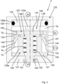
- Fig. 2 shows the fluid valve F in a second switching position, which is also a forced open position.
- Control pressure acts via the control connection 4 F in the control volume V S and on the control piston 122, so that the control piston 122 with a lower extension 122a, which is narrower in the radial direction than the control piston 122, applies pressure to the switching element 123 on the roof 137 and presses it downwards , against the resistance of the return spring 121.
- the collar 143 presses the sealing lip 132 downwards into the passage position shown.
- the lower sealing edge 133 has detached from the sealing surface 134 and a passage 147 has been created from the pressure inlet 1-1 F to the pressure outlet 2 F , so that pressure equalization takes place.
- the first limit value for the pressure at the control port 4 F and the second limit value for the pressure in the output volume V a are preferably between 1 and 3.5 bar, especially between 2 and 3 bar.
- the force of the return spring 121 and the two limit values mentioned are coordinated with one another.
- the sealing lip 132 does not necessarily have to assume a blocking position. It is also possible for the sealing lip 132 to be moved by the switching element 123 simply to achieve passages 147 of different sizes and/or for continuous adjustment of the passage 147. This then results in at least one passage position with a small passage and one passage position with a larger passage.
- the fluid valve F does not necessarily have to have the control piston 122 and the control connection 4 F.
- another type of control or action on the switching element 123 can also be present, such as an electromagnetic actuation such as a solenoid valve or a mechanical button.
- the fluid valve F can be used for all applications involving flowing media. In contrast to conventional slide valves or seat valves, the frictional forces in the fluid valve shown with a switchable lip seal are relatively low.
- the fluid valve shown can be used, for example, in a pneumatic brake system for a trailer vehicle, as is the case, for example DE 10 2016 005 625 A1 , Fig. 6 , is shown.
- a valve arrangement with the function of a parking release valve is shown at the bottom right of the figure, see reference number 23 there.
- a parking safety valve is also part of the valve arrangement, see there above the component with reference number 109.
- An emergency brake valve is provided as an external component, i.e. outside the valve arrangement , see reference number 37 there.
- a fluid valve according to the invention is in the Figures 4 to 10 shown as an example in the context of a specific embodiment of a parking safety valve and its function within a valve arrangement such as that in DE 10 2016 005 625 A1 disclosed valve arrangement.
- the latter can also be described as a valve arrangement with the function of a parking release valve and additional functions.
- Directional information used for explanation such as “top”, “bottom”, “side”, or terms with directional information, such as “bottom opening”, “bottom collar” and others, refer to the Representation in the figures.
- a twisted installation of the parking safety valve 216, 216a is possible. The directional information must then be adjusted accordingly.
- a valve arrangement 210 has a parking release valve 211 in the manner of a 5/3-way valve with an operating unit 212 and connections P1, P2, P3, P4, P5.
- the parking release valve 211 is provided with a control connection PS, via which a control piston 214 arranged in a control volume 213 can be acted upon for adjusting the parking release valve 211.
- valve arrangement 210 Part of the valve arrangement 210 is also an emergency brake valve 215 with connections N1, N2, N3 and control connection NS, in the manner of a 3/2-way valve.
- valve arrangement 210 Also part of the valve arrangement 210 is a parking safety valve 216 with connections 1-1 S , 2 S , 3 S and control inputs 4 Sa and 4 Sb , in the manner of a 3/2-way valve.
- valve arrangement 210 Also part of the valve arrangement 210 is an adjustable check valve 217 with connections VR1, VR2 and a control connection VRS.
- valve arrangement 210 part of the valve arrangement 210 is a simple check valve 218 with connections ER1 and ER2.
- connection designations are also each provided with a circle.
- connection of the valves 211, 215, 216, 217 and 218 with the connections mentioned is Fig. 4 removable. This is of particular importance Interconnection of the parking safety valve 16 with the other valves 211, 215, 217, 218.
- the port 1-1 S is connected to the supply port 1-1 as a pressure inlet.
- the connection 2 S is connected as a pressure output via a node 219 on the one hand to the control connection 4 Sb and on the other hand to the connection P1 of the parking release valve 211.
- the control port 4 Sa is connected via a node 220 to the control port 4 of the valve arrangement 210 and the port N1 of the emergency brake valve 215.
- the control connection VRS is pressurized so that the adjustable check valve 217 is in the check position shown.
- the parking safety valve 216 in Fig. 4 has a holding function. A blocking position is shown. This means that there is no continuity from the pressure inlet 1-1 S to the pressure outlet 2 S.
- the parking safety valve 216 switches to the open position, not shown, when a pressure above a limit value is fed in via the control connection 4 and the associated control connection 4 Sa , which overcomes the effect of a return spring 221.
- the pressure inlet 1-1 S is then connected to the pressure outlet 2 S.
- the holding function is active and the parking safety valve 216 remains in the open position.
- the parking safety valve 216 is used to supply the connection P1 of the parking release valve 211 in the driving position shown with supply pressure via the supply connection 1-1 only if after a pressure loss - for example by uncoupling a trailer vehicle from the towing vehicle - brake pressure was fed in at least once via the control connection 4.
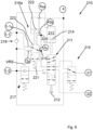
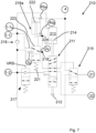
- the Fig. 5 to 7 show the pneumatic circuit diagram Fig. 4 with a slightly modified parking safety valve 216a, namely with a control piston 222 and in three different switching positions. Pressure at control port 4 Sa acts directly on control piston 222.
- the parking safety valve 216a In the first switching position according to Fig. 5 the parking safety valve 216a is in the locked position, like the parking safety valve 216 in Fig. 4 . There is no pressure at the control port 4 Sa , nor at the other control port 4 Sb . It is assumed that there is supply pressure at the supply connection 1-1, as well as at the pressure inlet 1-1 S , for example with an existing connection from the trailer vehicle to the towing vehicle and sufficient supply pressure in the towing vehicle.
- the parking release valve 211 is in the driving position.
- the emergency brake valve 215 does not receive any control pressure.
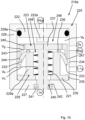
- control piston 222 switches a switching element 223 into the open position against the pressure of the return spring 221 Fig. 6 . Since the second control port 4 Sb is connected to the pressure output 2 S via the node 219 and a further node 224, the switching element 223 remains in the through position, even if there is no longer any pressure at the control port 4 Sa , see Fig. 7 . In addition, the control piston 222 is moved back into the position according to the pressure at the control connection 4 Sb Fig. 5 .
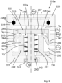
- FIG. 8 to 10 An exemplary embodiment of the parking safety valve 216a is shown in axial section in FIG Fig. 8 to 10 shown, matching the Fig. 5 to 7 and analogous to the Fig. 1 to 3 .
- the parking safety valve 216a corresponds in structure and function to the fluid valve F, apart from the control connection 4 Sb . All features and functions mentioned in connection with the fluid valve F can also be provided for the parking safety valve 216a.
- control piston 222 is axially movable in an upper region, below the control connection 4 Sa , and is provided with a circumferential seal 228a.
- a lip seal 229 is arranged on the bottom wall 227, which has a cup-shaped lip holder 229a with a cup opening 248 and a bottom-side, radially directed bottom collar 230.
- a collar-like sealing lip 232 extends outwards from an upper edge 231 of the lip holder 229a.
- the sealing lip 232 is directed obliquely downwards and lies in the in Fig. 8 shown blocking position and at the same time first switching position with a lower sealing edge 233 on a sealing surface 234 of the housing 225.
- the bottom collar 230 is additionally provided with a sealing bead 235 on the radial outside, which rests on the inside on the side wall 228 and/or on the bottom wall 227.
- a circumferential sealing bead 236 is provided on the upper edge 231.
- the housing 225 has the pressure inlet 1-1S and the pressure outlet 2S on the side.
- the sealing surface 234 lies between pressure inlet 1-1S and pressure outlet 2S .
- the T-shaped switching element 223 is arranged between the control piston 222 and the lip seal 229 and has a roof 237 with a trunk 238 underneath.
- the trunk 238 extends from above into the cup opening 248 and through a bottom opening 239 of the lip holder 229a and a bottom opening 240 of the housing 225 and is held with a lower widening 241 in the opening 240 having a shoulder 242.
- the return spring 221 sits on the trunk 238, pushes the roof 237 upwards with the trunk 238 and is supported in the cup-shaped lip holder 229a, so that the widening 241 rests on the shoulder 242, see locking position in Fig. 8 .
- the widening 241 does not completely close the opening 240, so that pressure equalization via the opening 240 remains possible.
- the roof 237 is provided radially on the outside with a downwardly directed collar 243, the lower edge 244 of which supports the sealing lip 232 on the outside or rests against it without pressure.
- the sealing bead 236 is at a distance from the roof 237.
- An interior 246 of the housing 225 is at least divided into an input volume V e connected to the pressure inlet 1-1 S , an output volume V a connected to the pressure outlet 2 S , a relief volume connected to the relief outlet 3 S via the bottom opening 239 and the opening 240 V 3 and a control volume V S connected to the control connection 4 Sa.
- the relief output 3 S has the particular function of ventilation.
- Fig. 9 shows the parking safety valve 216a in a second switching position, as also in Fig. 6 shown.
- control pressure acts in the control volume V S and on the control piston 222, so that the latter applies pressure to the switching element 223 with a lower extension 222a and presses it downwards on the roof 237, against the resistance of the return spring 221.
- the collar 243 presses the sealing lip 232 downwards into a passage position.
- the lower sealing edge 233 detaches from the sealing surface 234 and a passage 247 is created from the pressure inlet 1-1 S to the pressure outlet 2 S , so that the same pressure is applied in each case.
- the roof 237 comes into contact with the sealing bead 236. Pressure equalization within a trapped volume V g formed thereby between the sealing bead 236, the collar 243 and the sealing lip 232 radially outside the sealing bead 236 is possible through the flow channels 245.
- the pressure at the control port 4 Sa in Fig. 9 and the sufficient pressure in the initial volume V a is preferably between 1 and 3.5 bar, in particular between 2 and 3 bar.
- the friction forces in the parking safety valve shown with a switchable lip seal are relatively low.
- Valve assembly connections 129a Lip holder 1-1 Supply connection 130 Floor collar 1-2 Reservoir connection 131 upper edge 21 Brake pressure connection 132 sealing lip 22 Spring storage connection 133 bottom edge 3 Venting 134 sealing surface 4 Control connection 135 sealing bead 136 sealing bead Fluid valve connections 137 Roof 1-1 F Pressure input 138 tribe 2 F Pressure output 139 Bottom opening (lip seal) 3 F Relief exit 140 opening (housing) 4 F Control connection 141 widening 142 Paragraph Parking safety valve connections 143 collar 1-1 p Pressure input 144 bottom edge 2 p Pressure output 145 Flow channels 3 p Relief exit 146 inner space 4 Sat Control connection 147 passage 4 Sb Control connection 148 Cup opening 121 return spring 210 Valve arrangement 122 control piston 211 Parking release valve 122a appendage 212 Operating unit 123 Switching element 213 Tax volume 125 Housing 214 control piston 126 Upper wall 215 Emergency brake valve 127 floor wall 216 Parking safety valve 128 Side wall 216a Parking safety valve 128a all-round seal 217 adjustable check valve
Landscapes
- Engineering & Computer Science (AREA)
- Mechanical Engineering (AREA)
- Transportation (AREA)
- General Engineering & Computer Science (AREA)
- Physics & Mathematics (AREA)
- Fluid Mechanics (AREA)
- Valves And Accessory Devices For Braking Systems (AREA)
- Safety Valves (AREA)
Description
- Die Erfindung betrifft ein Fluidventil gemäß dem Oberbegriff des Anspruchs 1. Daneben betrifft die Erfindung eine pneumatische Ventilanordnung und eine pneumatische Bremsanlage für ein Fahrzeug, insbesondere für ein Anhängefahrzeug.
- Als Fluidventile werden hier Ventile für alle strömenden Medien verstanden, insbesondere Pneumatikventile, vorzugsweise zur Verwendung in pneumatischen Bremsanlagen. Pneumatische Bremsanlagen in Anhängefahrzeugen mit Parklöseventil können verschiedene Sicherheitsfunktionen erfüllen. Beispielsweise kann eine sogenannte Park/Save-Funktion vorgesehen sein, die eine gefährliche Situation in Verbindung mit einer Fehlbedienung vermeiden soll. Beim Ankoppeln eines Anhängefahrzeugs an ein Zugfahrzeug soll das Parklöseventil in Parkstellung stehen. Selbst wenn sich das Parklöseventil aber in seiner Fahrtstellung befindet, ist das noch nicht angekoppelte Anhängefahrzeug gebremst, da vorhandene Federspeicherbremsen dann entlüftet und wirksam sind. Wird in dieser Situation mit dem Parklöseventil in der Fahrtstellung nun irrtümlich zunächst die Vorratsdruckleitung des Anhängefahrzeugs mit dem Zugfahrzeug verbunden, werden, wenn die Bremsanlage des Anhängefahrzeugs keine Park/Save-Funktion aufweist, die Federspeicherbremsen belüftet und gelöst. Das Anhängefahrzeug kann sich bewegen, obwohl dies zu diesem Zeitpunkt nicht gewünscht ist und Gefahr für Bedienungspersonen besteht. Die Park/Save-Funktion bewirkt demgegenüber, dass die Federspeicherbremsen unter diesen Bedingungen noch nicht belüftet und gelöst werden. Vielmehr muss wenigstens einmal die Betriebsbremse betätigt werden. Der dabei eingesteuerte Bremsdruck wirkt als Steuerdruck für die Aufhebung der Park/Save-Funktion. Die Park/Save-Funktion und eine mögliche konstruktive Lösung sind dargestellt in der
DE 10 2016 005 625 A1 , insbesondere im Zusammenhang mit denFig. 6 bis 11. - Die Park/Save-Funktion kann in ein sogenanntes Parklöseventil integriert oder Bestandteil einer Ventilanordnung sein, mit der eine Parklöse-Funktion realisiert ist. Die
Fig. 7 derDE 10 2016 005 625 A1 zeigt hierzu ein pneumatisches Schaltbild, dieFig. 8 bis 11 ein hoch integriertes Parklöseventil, passend zum pneumatischen Schaltbild. Die Park/Save-Funktion ergibt sich aus dem Zusammenwirken eines Steuerschiebers 105 mit einem Sperrschieber 104 und zugehörigen Dichtungen und Strömungskanälen. - Durch geringere Integration ist ein einfacherer Aufbau der einzelnen Bestandteile möglich. Das Parklöseventil kann als einfaches Schieberventil ausgeführt werden, während die Park/Save-Funktion durch ein eigens hierfür vorgesehenes Ventil realisierbar ist.
-
EP 3 477 168 A1 offenbart ein Ventil mit einem Druckeingang und einem Druckausgang sowie mit einem Schaltelement, das entlang einer Achse zwischen einem ersten Anschlag und einem zweiten Anschlag bewegbar ist. Weiterhin weist das Ventil eine Membran auf, die als Rückschlagelement wirkt. Das Ventil weist eine Durchlasstellung auf, in der das Schaltelement an dem ersten Anschlag anliegt. Das Ventil weist weiterhin eine Sperrstellung auf, in der das Schaltelement an dem zweiten Anschlag anliegt. Das Schaltelement kann in der Sperrstellung an der Membran anliegen: Ist ein Druck am Druckausgang höher als ein Druck am Druckeingang, wird die Membran gegen das Schaltelement gepresst; ist der Druck am Druckeingang dagegen höher als der Druck am Druckausgang, hebt die Membran von dem Schaltelement ab (Rückschlagfunktion). - Aufgabe der vorliegenden Erfindung ist die Schaffung eines Fluidventils, welches als Parksicherheitsventil bzw. zur Realisierung der Park/Save-Funktion geeignet ist. Insbesondere soll das Fluidventil möglichst zuverlässig, leichtgängig und wartungsfrei sein.
- Zur Lösung der Aufgabe weist das erfindungsgemäße Fluidventil die Merkmale des Anspruchs 1 auf. Danach ist das Fluidventil zwischen einem Druckeingang und einem Druckausgang mit einer eine Dichtlippe aufweisenden Lippendichtung versehen, wobei eine Position der Dichtlippe zur Veränderung eines Durchlassquerschnitts veränderbar ist. Erfindungsgemäß kann die Dichtlippe unterschiedliche Positionen einnehmen, sodass ein Durchlassquerschnitt zwischen Druckeingang und Druckausgang einstellbar ist. Vorzugsweise wird die Dichtlippe nicht insgesamt bewegt. Vielmehr wird nur ein Teil der Dichtlippe relativ zur Lippendichtung abgewinkelt oder verbogen. Die Dichtlippe kann hierzu aus entsprechend elastischem Werkstoff hergestellt sein, ebenso die Lippendichtung insgesamt.
- Das Fluidventil ist insbesondere für pneumatische Bremsanlagen in Anhängefahrzeugen vorgesehen, kann aber auch für andere Anwendungen im Zusammenhang mit strömenden Medien eingesetzt werden. Im Gegensatz zu herkömmlichen Schieberventilen oder Sitzventilen sind die Reibungskräfte in dem dargestellten Fluidventil mit schaltbarer Lippendichtung relativ gering.
- Nach einem weiteren Gedanken der Erfindung ist vorgesehen, dass die Dichtlippe in einer Sperrstellung an einer Dichtfläche anliegt und in einer Durchlassstellung einen Abstand zur Dichtfläche aufweist. Durch den Abstand und gegebene geometrische Verhältnisse wird der Durchlassquerschnitt definiert.
- Nach einem weiteren Gedanken der Erfindung kann vorgesehen sein, dass die Dichtlippe eine Eigenspannung aufweist, welche die Dichtlippe zur Verringerung des Durchlassquerschnitts beaufschlagt. Das heißt, ohne Beeinflussung durch andere Bauelemente ist die Dichtlippe bestrebt, die Position mit dem geringsten Durchlassquerschnitt einzunehmen. Insbesondere liegt die Dichtlippe dann an einer Dichtfläche an. Vorteilhafterweise erstreckt sich die Dichtlippe unter einem spitzen Winkel zur Dichtfläche und ist selbsthaltend angeordnet, das heißt, bei größerem Druck am Druckeingang als am Druckausgang wird die Dichtlippe durch die Druckdifferenz gegen die Dichtfläche gedrückt und hält so die oben genannte Sperrstellung.
- Die Position der Dichtlippe ist durch Druck eines Schaltelements veränderbar. Mit dem Schaltelement wird mittelbar der Durchlassquerschnitt verändert. Dabei wirkt der Druck des Schaltelements vorzugsweise der Eigenspannung der Dichtlippe entgegen. Das Schaltelement wird zur Veränderung der Position der Dichtlippe verwendet und kann selbst beispielsweise durch ein Fluid angesteuert werden. Durch Bewegung des Schaltelements kann der Druck des Schaltelements ausgeübt werden und ist die Dichtlippe schaltbar, sodass wahlweise die Verbindung vom Druckeingang zum Druckausgang geöffnet und geschlossen oder einfach nur der Durchlassquerschnitt verändert werden kann. Durch Veränderung des Durchlassquerschnitts ist die Dichtlippe somit stufenlos schaltbar. Die Beaufschlagung der Dichtlippe durch das Schaltelement kann mittelbar oder unmittelbar erfolgen. Beispielsweise kann zwischen Schaltelement und Dichtlippe ein zusätzliches Bauteil vorgesehen sein. Das Schaltelement wirkt dann nur mittelbar auf die Dichtlippe.
- Nach einem weiteren Gedanken der Erfindung kann vorgesehen sein, dass sich die Dichtlippe in einer Sperrstellung am Schaltelement abstützt. Die Dichtlippe liegt dann in Sperrstellung einerseits an der Dichtfläche an und wird andererseits vom Schaltelement abgestützt, vorzugsweise von einem Rand oder Kragen des Schaltelements.
- Nach einem weiteren Gedanken der Erfindung kann das Schaltelement an der Dichtlippe anliegen, wobei die Dichtlippe durch das Schaltelement zur Vergrößerung des Durchlassquerschnitts beaufschlagbar ist. Insbesondere beaufschlagt das Schaltelement die Dichtlippe in einer Durchlassstellung stärker als in der Sperrstellung.
- Nach einem weiteren Gedanken der Erfindung kann die Lippendichtung einen Lippenhalter aufweisen, an dem die Dichtlippe gehalten ist. Ein Winkel der Dichtlippe zum Lippenhalter kann durch mechanischen Druck des Schaltelements änderbar sein. Die Änderung des Winkels kann sich auch durch Verformung der Dichtlippe ergeben.
- Nach einem weiteren Gedanken der Erfindung kann das Schaltelement pilzförmig mit Stamm und Dach ausgebildet sein. Der Lippenhalter kann becherförmig mit einer Becheröffnung und einem Boden ausgebildet sein, wobei der Boden eine Bodenöffnung aufweist. Der Stamm kann in die Becheröffnung hineinreichen bis in die Bodenöffnung. Das Dach kann dann in der Durchlassstellung an der Lippendichtung anliegen. Die Lippendichtung oder das Dach können mit einer Dichtwulst versehen sein. Das Dach dichtet auf diese Weise in der Durchlassstellung der Lippendichtung die Becheröffnung ab.
- Nach einem weiteren Gedanken der Erfindung kann das Dach einen umlaufenden Kragen aufweisen, welcher zum Boden des Lippenhalters geneigt ist, wobei sich die Dichtlippe von einem Rand neben der Becheröffnung umlaufend nach außen erstreckt, und wobei die Dichtlippe in Durchlassstellung vom Kragen des Daches beaufschlagt wird. Vorzugsweise beaufschlagt der Kragen die Dichtlippe während der gesamten Betätigung der Dichtlippe, insbesondere auch in der Sperrstellung.
- Nach einem weiteren Gedanken der Erfindung kann das Schaltelement in Richtung auf eine Entlastung der Dichtlippe durch eine Rückstellfeder beaufschlagt sein. Die Rückstellfeder wirkt gegen das Schaltelement und muss durch Druck am Steueranschluss oder Druckausgang zusätzlich überwunden werden, ebenso wie die Eigenspannung der Dichtlippe.
- Das Fluidventil kann ein Gehäuse aufweisen.
- Nach einem weiteren Gedanken der Erfindung kann vorgesehen sein, dass das Schaltelement in dem Gehäuse gegen die Wirkung der Rückstellfeder bewegbar ist, und dass eine Verbreiterung des Schaltelements bei minimiertem Durchlassquerschnitt durch die Wirkung der Rückstellfeder an einem Absatz des Gehäuses anliegt. Rückstellfeder, Verbreiterung und Absatz definieren eine Endposition des im Gehäuse des Fluidventils bewegbaren Schaltelements.
- Nach einem weiteren Gedanken der Erfindung kann der Lippenhalter in dem Gehäuse fest stehend angeordnet sein. Der Lippenhalter ist dann ebenso wie die Dichtlippe Teil der Lippendichtung. Der Lippenhalter ist feststehend vorgesehen, während die Dichtlippe bewegbar oder flexibel ist. Bei der Veränderung des Durchlassquerschnitts ändert die Dichtlippe ihre Form, ihre Position und/oder ihren Winkel relativ zum Lippenhalter.
- Nach einem weiteren Gedanken der Erfindung kann das Gehäuse einen zylindrischen Innenraum aufweisen. In dem Innenraum kann das Schaltelement in Axialrichtung bewegbar sein. In dem Innenraum kann außerdem die Lippendichtung gehalten sein. Schaltelement und Lippendichtung sind vorzugsweise an die zylindrische Gestalt des Innenraums angepasst.
- Nach einem weiteren Gedanken der Erfindung kann die Dichtlippe bei geschlossenem Durchlassquerschnitt den Innenraum aufteilen in ein mit dem Druckausgang verbundenes Ausgangsvolumen und ein mit dem Druckeingang verbundenes Eingangsvolumen. Bei nicht geschlossenem Durchlassquerschnitt sind Ausgangsvolumen und Eingangsvolumen über den Durchlassquerschnitt miteinander verbunden.
- Nach einem weiteren Gedanken der Erfindung kann zwischen Lippendichtung und Schaltelement ein mit einem Entlastungsausgang verbundenes Entlastungsvolumen gebildet sein, wobei das Entlastungsvolumen und das Ausgangsvolumen über einen Strömungskanal im Schaltelement zumindest in einer Sperrstellung der Dichtlippe miteinander verbunden sind. Dadurch liegt in Sperrstellung im Ausgangsvolumen ein definierter Druck vor, nämlich wie im Entlastungsvolumen, welches mit dem Entlastungsausgang verbunden ist. Der Druck am Entlastungsausgang entspricht typischerweise einem Umgebungsdruck des Fluidventils.
- Nach einem weiteren Gedanken der Erfindung kann eine Verbindung vom Entlastungsvolumen zum Strömungskanal in Durchlassstellung der Dichtlippe verschlossen sein durch eine Dichtung zwischen Lippendichtung und Schaltelement. Durch die Dichtung wird das Entlastungsvolumen vom Strömungskanal und dem damit verbundenen Ausgangsvolumen getrennt. Auf diese Weise ist der Strömungskanal in Durchlassstellung sicher verschlossen.
- Nach einem weiteren Gedanken der Erfindung kann in einem Gehäuse des Fluidventils ein zwischen einer Ausgangsstellung und einer Betätigungsstellung bewegbarer Steuerkolben vorhanden sein, welcher durch Druck an einem Steueranschluss aus seiner Ausgangsstellung bewegbar ist und in der Betätigungsstellung ein Schaltelement zur Betätigung der Dichtlippe beaufschlagt. Mit der Bewegung des Steuerkolbens in die Betätigungsstellung geht die Dichtlippe in Durchlassstellung.
- Nach einem weiteren Gedanken der Erfindung kann der Steuerkolben ein mit dem Steueranschluss verbundenes Steuervolumen von einem mit dem Druckausgang verbundenen Ausgangsvolumen trennen. Vorzugsweise ist der Steuerkolben hierzu mit einer umlaufenden Dichtung versehen. Durch ansteigenden Druck im Steuervolumen ist der Steuerkolben zur Verringerung des Ausgangsvolumens bewegbar.
- Nach einem weiteren Gedanken der Erfindung können wenigstens zwei Schaltstellungen vorgesehen sein, nämlich die Sperrstellung und die Durchlassstellung. Weiterhin können wenigstens vier Anschlüsse vorgesehen sein, nämlich der Druckeingang, der Druckausgang, ein Entlastungsausgang und ein Steueranschluss. Weiterhin kann in dem Gehäuse ein Schaltelement bewegbar sein. Das bewegbare Schaltelement kann dazu vorgesehen sein, den Durchlassquerschnitt vom Druckeingang zum Druckausgang in Abhängigkeit vom Druck am Druckausgang und am Steueranschluss wahlweise zu öffnen oder zu schließen. Das Schaltelement kann eine Haltefunktion aufweisen, wobei die Haltefunktion so ausgestaltet ist, dass der Durchlassquerschnitt geöffnet ist, wenn der Druck am Steueranschluss oberhalb eines ersten Grenzwerts liegt, und auch dann geöffnet bleibt, wenn der Druck am Steueranschluss wieder unter den ersten Grenzwert fällt, dabei aber am Druckausgang ein Druck oberhalb eines zweiten Grenzwerts anliegt. Durch die vorgesehene Haltefunktion können mit dem Fluidventil besondere Funktionen erfüllt werden, beispielsweise als Parksicherheitsventil in einer pneumatischen Bremsanlage. Die genannten Grenzwerte liegen vorzugsweise zwischen 1 und 3,5 bar, insbesondere zwischen 2 und 3 bar. Der erste und der zweite Grenzwert können identisch sein, können sich aber auch unterscheiden.
- Eine pneumatische Ventilanordnung mit einem Parklöseventil weist zur Lösung der Aufgabe ein Fluidventil nach einem der Ansprüche 1 bis 18 auf. Das Fluidventil hat dabei vorzugsweise die Aufgabe eines Parksicherheitsventils. Die Ventilanordnung ist vorzugsweise für eine Bremsanlage eines Fahrzeugs, insbesondere für eine Bremsanlage eines Anhängefahrzeugs, vorgesehen.
- Nach einem weiteren Gedanken der Erfindung kann der Druckeingang des Fluidventils mit einem unter Vorratsdruck stehenden Versorgungsanschluss der Ventilanordnung verbunden sein, wobei der Druckausgang des Fluidventils mit einem Anschluss des Parklöseventils verbunden ist und ein Steueranschluss des Fluidventils mit einem Steueranschluss der Ventilanordnung verbunden ist. Der Steueranschluss der Ventilanordnung ist vorzugsweise mit Bremsdruck aus der pneumatischen Bremsanlage beaufschlagbar. Der Versorgungsanschluss der Ventilanordnung erhält in einem Anhängefahrzeug den Vorratsdruck von einem Kupplungskopf "Vorrat", während der Bremsdruck über einen Kupplungskopf "Bremse" zugeführt wird.
- Gegenstand der Erfindung ist auch eine pneumatische Bremsanlage für ein Anhängefahrzeug, mit einem Fluidventil nach einem der Ansprüche 1 bis 19 oder mit einer Ventilanordnung nach einem der Ansprüche 20 und 21.
- Weitere Merkmale der Erfindung ergeben sich aus der Beschreibung im Übrigen und aus den Patentansprüchen. Vorteilhafte Ausführungsbeispiele der Erfindung werden nachfolgend anhand von Zeichnungen näher erläutert. Es zeigen:
- Fig. 1
- einen Axialschnitt durch ein Fluidventil in einer ersten Schaltstellung, nämlich in einer Sperrstellung,
- Fig. 2
- einen der
Fig. 1 entsprechende Axialschnitt in einer zweiten Schaltstellung, nämlich in einer Durchlassstellung, - Fig. 3
- einen der
Fig. 1 entsprechenden Axialschnitt in einer dritten Schaltstellung, nämlich in einer selbsthaltenden Durchlassstellung, - Fig. 4
- ein pneumatisches Schaltbild einer Ventilanordnung mit einem Parklöseventil, einem Parksicherheitsventil, einem schaltbaren Rückschlagventil und einem Notbremsventil,
- Fig. 5
- ein gegenüber
Fig. 4 abgewandeltes pneumatisches Schaltbild mit der Ventilanordnung in derselben ersten Schaltstellung, - Fig. 6
- ein der
Fig. 5 entsprechendes pneumatisches Schaltbild mit der Ventilanordnung in einer zweiten Schaltstellung, - Fig. 7
- ein der
Fig. 5 entsprechendes pneumatisches Schaltbild mit der Ventilanordnung in einer dritten Schaltstellung, - Fig. 8
- einen Axialschnitt durch ein Parksicherheitsventil in der ersten Schaltstellung gemäß
Fig. 5 , - Fig. 9
- einen der
Fig. 8 entsprechenden Axialschnitt mit dem Parksicherheitsventil in der zweiten Schaltstellung gemäßFig. 6 , - Fig. 10
- einen der
Fig. 8 entsprechenden Axialschnitt mit dem Parksicherheitsventil in der dritten Schaltstellung gemäßFig. 7 . - Ein in den
Fig. 1 bis 3 dargestelltes Fluidventil F ist vorzugsweise ein 3/2-WegeVentil, kann für hydraulische oder pneumatische oder gemischte Anwendungen vorgesehen sein und weist mindestens zwei Schaltstellungen und mindestens drei Anschlüsse für Eingänge und Ausgänge auf. Zusätzlich ist hier wenigstens ein Steueranschluss vorgesehen. Die Anschlüsse bzw. Eingänge/Ausgänge sind mit einer in der Fluidtechnik üblichen Bezifferung und zusätzlich mit einem Index F versehen: - 1-1F
- Druckeingang
- 2F
- Druckausgang
- 3F
- Entlastungsausgang
- 4F
- Steueranschluss
- Zur Verdeutlichung und zur Unterscheidung von weiteren Bezugsziffern sind die zuvor genannten Ziffern in den Figuren jeweils mit einem Umkreis versehen.
- Details des Fluidventils F werden anhand der in den Figuren dargestellten Ausrichtung erläutert. Dabei verwendete Richtungsangaben, wie "oben", "unten", "seitlich", oder Begriffe mit Richtungsangaben beziehen sich auf die Darstellung in den Figuren. Eine demgegenüber verdrehte Anordnung des Fluidventils F ist möglich. Die Richtungsangaben sind dann entsprechend anzupassen.
- Das Fluidventil F weist ein zylindrisches Gehäuse 125 mit Oberwand 126, Bodenwand 127 und umlaufender Seitenwand 128 auf. Der Steueranschluss 4F ist im Bereich der Oberwand 126 vorgesehen. Im Gehäuse 125 ist unterhalb der Oberwand 126 ein Steuerkolben 122 axial bewegbar und mit einer umlaufenden Dichtung 128a versehen.
- Auf der Bodenwand 127 ist eine Lippendichtung 129 angeordnet, welche einen becherförmigen Lippenhalter 129a mit einer Becheröffnung 148 und mit einem bodenseitigen, radial gerichteten Bodenkragen 130 aufweist. Von einem oberen Rand 131 des becherförmigen Lippenhalters 129a erstreckt sich nach außen eine kragenartige Dichtlippe 132. Die Dichtlippe 132 ist schräg abwärts gerichtet und liegt in der in
Fig. 1 gezeigten ersten Schaltstellung/Sperrstellung mit einem unteren Dichtrand 133 an einer Dichtfläche 134 des Gehäuses 125 an. Die Dichtfläche 134 ist hier innen an der Seitenwand 128 vorgesehen. - Das Gehäuse 125 weist seitlich den Druckeingang 1-1F und axial darüber den Druckausgang 2F auf. Die Dichtfläche 134 liegt zwischen dem Druckeingang 1-1F und dem Druckausgang 2F.
- Der Bodenkragen 130 ist radial außen zusätzlich mit einer Dichtwulst 135 versehen, die innen an der Seitenwand 128 und/oder an der Bodenwand 127 anliegt. Auf dem oberen Rand 131 ist eine umlaufende Dichtwulst 136 vorgesehen.
- Zwischen dem Steuerkolben 122 und der Lippendichtung 129 ist ein hier T-förmig ausgebildetes Schaltelement 123 angeordnet, welches ein Dach 137 mit darunter stehendem Stamm 138 aufweist. Der Stamm 138 erstreckt sich von oben in die Becheröffnung 148 hinein und durch eine Bodenöffnung 139 des Lippenhalters 129a hindurch. Zugleich erstreckt sich der Stamm 138 durch eine bodenseitige Öffnung 140 des Gehäuses 125 hindurch. Dabei ist der Stamm 138 mit einer unteren Verbreiterung 141 in der einen Absatz 142 aufweisenden Öffnung 140 gehalten. Die Bodenöffnung 139 und die Öffnung 140 des Gehäuses 125 sind koaxial angeordnet.
- Eine Rückstellfeder 121 sitzt auf dem Stamm 138, drückt das Dach 137 mit dem Stamm 138 nach oben und stützt sich dabei in dem becherförmigen Lippenhalter 129a ab, sodass die Verbreiterung 141 von unten am Absatz 142 anliegt, siehe die erste Schaltstellung/Sperrstellung in
Fig. 1 . Dabei verschließt die Verbreiterung 141 die Öffnung 140 nicht vollständig, sodass ein Druckausgleich über die Öffnung 140 und den daran anschließenden Entlastungsausgang 3F möglich bleibt. - Das Dach 137 des Schaltelements 123 ist radial außen mit einem abwärts gerichteten Kragen 143 versehen, dessen unterer Rand 144 die Dichtlippe 132 außen abstützt oder ohne Druck an dieser anliegt. Die Dichtwulst 136 weist in
Fig. 1 einen Abstand zum Dach 137 auf. Im Dach 137 befinden sich Strömungskanäle 145, sodass ein Raum zwischen Dichtwulst 136 und Kragen 143 belüftbar ist. - Ein Innenraum 146 des Gehäuses 125 ist zumindest unterteilt in ein mit dem Druckeingang 1-1F verbundenes Eingangsvolumen Ve, ein mit dem Druckausgang 2F verbundenes Ausgangsvolumen Va, ein insbesondere über die Bodenöffnung 139 und die Öffnung 140 mit dem Entlastungsausgang 3F verbundenes Entlastungsvolumen V3 und ein mit dem Steueranschluss 4F verbundenes Steuervolumen VS.
-
Fig. 2 zeigt das Fluidventil F in einer zweiten Schaltstellung, die zugleich eine erzwungene Durchlassstellung ist. Über den Steueranschluss 4F wirkt Steuerdruck im Steuervolumen VS und auf den Steuerkolben 122, sodass der Steuerkolben 122 mit einem unteren Fortsatz 122a, welcher in Radialrichtung schmaler ist als der Steuerkolben 122, das Schaltelement 123 durch Druck auf das Dach 137 beaufschlagt und abwärts drückt, gegen den Widerstand der Rückstellfeder 121. Dabei drückt der Kragen 143 die Dichtlippe 132 abwärts in die gezeigte Durchlassstellung. Der untere Dichtrand 133 hat sich von der Dichtfläche 134 gelöst und es ist ein Durchlass 147 vom Druckeingang 1-1F zum Druckausgang 2F entstanden, sodass ein Druckausgleich stattfindet. Zugleich kommt das Dach 137 zur Anlage an der Dichtwulst 136. Ein Druckausgleich innerhalb eines dadurch gebildeten gefangenen Volumens Vg zwischen der Dichtwulst 136, dem Kragen 143 und der Dichtlippe 132 radial außerhalb der Dichtwulst 136 ist möglich durch die Strömungskanäle 145. - Ausgehend von der zweiten Schaltstellung in
Fig. 2 wird anschließend über den Steueranschluss 4F kein Steuerdruck mehr zugeführt. Es kommt zu der inFig. 3 gezeigten dritten Schaltstellung. Auch dabei handelt es sich um eine Durchlassstellung, jedoch ohne Beaufschlagung des Schaltelements 123 durch den Steuerkolben 122. Durch den im Ausgangsvolumen Va vorherrschenden Druck wirkt auch eine Kraft auf das Schaltelement 123 in Abwärtsrichtung, sodass die Dichtlippe 132 in Durchlassstellung bleibt und der Durchlass 147 offen gehalten wird. Außerdem wird der Steuerkolben 122 aufwärts gedrückt in Richtung auf den Steueranschluss 4F und in die Position wie in denFig. 1 und3 dargestellt, also bis zur Anlage an der Oberwand 126. - Zusammengefasst sind folgende Zustände in den
Fig. 1 bis 3 gezeigt: - in Fig. 1
- die Sperrstellung von Dichtlippe 132 und Schaltelement 123 und eine Ausgangsstellung des Steuerkolbens 122, ohne Druck am Steueranschluss 4F,
- in Fig. 2
- die erzwungene Durchlassstellung von Dichtlippe 132 und Schaltelement 123 und eine Betätigungsstellung des Steuerkolbens 122 bei Druck am Steueranschluss 4F oberhalb eines ersten Grenzwerts,
- in Fig. 3
- die selbsthaltende Durchlassstellung von Dichtlippe 132 und Schaltelement 123 und die Ausgangsstellung des Steuerkolbens 122 nach Druckrückgang am Steueranschluss 4F, bei Druck im Ausgangsvolumen Va oberhalb eines zweiten Grenzwerts.
- Der erste Grenzwert für den Druck am Steueranschluss 4F und der zweite Grenzwert für den Druck im Ausgangsvolumen Va liegen vorzugsweise zwischen 1 und 3,5 bar, insbesondere zwischen 2 und 3 bar. Die Kraft der Rückstellfeder 121 und die beiden genannten Grenzwerte sind aufeinander abgestimmt.
- Anders als in
Fig. 1 dargestellt, muss die Dichtlippe 132 nicht zwingend eine Sperrstellung einnehmen. Möglich ist auch eine Bewegung der Dichtlippe 132 durch das Schaltelement 123 lediglich zur Erzielung unterschiedlich großer Durchlässe 147 und/oder zur stufenlosen Verstellung des Durchlasses 147. Es ergeben sich dann zumindest eine Durchlassstellung mit kleinem Durchlass und eine Durchlassstellung mit demgegenüber größerem Durchlass. - Ebenfalls abweichend von der Darstellung in den Figuren muss das Fluidventil F nicht zwingend den Steuerkolben 122 und den Steueranschluss 4F aufweisen. Stattdessen kann auch eine andere Art der Steuerung oder Beaufschlagung des Schaltelements 123 vorhanden sein, etwa eine elektromagnetische Betätigung wie bei einem Magnetventil oder ein mechanischer Taster. Wichtig sind Lippendichtung 129, Schaltelement 123, Druckeingang 1-1F, Druckausgang 2F, Entlastungsausgang 3F und vorzugsweise die Rückstellfeder 121 oder ein anderes Rückstellelement und irgendeine Art der Betätigung des Schaltelements 123.
- Das Fluidventil F kann für alle Anwendungen im Zusammenhang mit strömenden Medien eingesetzt werden. Im Gegensatz zu herkömmlichen Schieberventilen oder Sitzventilen sind die Reibungskräfte in dem dargestellten Fluidventil mit schaltbarer Lippendichtung relativ gering.
- Das dargestellte Fluidventil kann beispielsweise Einsatz finden in einem pneumatischen Bremssystem für ein Anhängefahrzeug, wie es beispielsweise in der
DE 10 2016 005 625 A1 ,Fig. 6 , dargestellt ist. Rechts unten in der Figur ist eine Ventilanordnung mit der Funktion eines Parklöseventils dargestellt, siehe dort Bezugsziffer 23. Bestandteil der Ventilanordnung ist auch ein Parksicherheitsventil, siehe dort oberhalb des Bauteils mit der Bezugsziffer 109. Als externes Bauteil, also außerhalb der Ventilanordnung ist ein Notbremsventil vorgesehen, siehe dort Bezugsziffer 37. - Ohne dass dadurch eine Beschränkung der Erfindung bewirkt werden soll, ist ein erfindungsgemäßes Fluidventil in den
Figuren 4 bis 10 beispielhaft dargestellt im Kontext einer konkreten Ausgestaltung eines Parksicherheitsventils und dessen Funktion innerhalb einer Ventilanordnung wie beispielsweise der inDE 10 2016 005 625 A1 offenbarten Ventilanordnung. Letztere ist auch beschreibbar als Ventilanordnung mit der Funktion eines Parklöseventils und Zusatzfunktionen. - Wie für die Darstellung des Fluidventils F gilt auch im Folgenden: Zur Erläuterung verwendete Richtungsangaben, wie "oben", "unten", "seitlich", oder Begriffe mit Richtungsangaben, wie "Bodenöffnung", "Bodenkragen" und andere, beziehen sich auf die Darstellung in den Figuren. Ein demgegenüber verdrehter Einbau des Parksicherheitsventils 216, 216a ist möglich. Die Richtungsangaben sind dann entsprechend anzupassen.
- Eine Ventilanordnung 210 weist ein Parklöseventil 211 nach Art eines 5/3-WegeVentils mit Bedienungseinheit 212 und Anschlüssen P1, P2, P3, P4, P5 auf. Außerdem ist das Parklöseventil 211 mit einem Steueranschluss PS versehen, über den ein in einem Steuervolumen 213 angeordneter Steuerkolben 214 zum Verstellen des Parklöseventils 211 beaufschlagbar ist.
- Bestandteil der Ventilanordnung 210 ist weiterhin ein Notbremsventil 215 mit Anschlüssen N1, N2, N3 und Steueranschluss NS, nach Art eines 3/2-WegeVentils.
- Weiterhin Bestandteil der Ventilanordnung 210 ist ein Parksicherheitsventil 216 mit Anschlüssen 1-1S, 2S, 3S und Steuereingängen 4Sa und 4Sb, nach Art eines 3/2-Wege-Ventils.
- Weiterhin Bestandteil der Ventilanordnung 210 ist ein verstellbares Rückschlagventil 217 mit Anschlüssen VR1, VR2 und einem Steueranschluss VRS.
- Schließlich ist Bestandteil der Ventilanordnung 210 noch ein einfaches Rückschlagventil 218 mit Anschlüssen ER1 und ER2.
- Die Ventilanordnung 210 ist in die nicht näher gezeigte pneumatische Bremsanlage eines Anhängefahrzeugs eingebunden, ähnlich wie in der
DE 10 2016 005 625 A1 dargestellt. In pneumatischen Schaltbildern sind Eingänge und Ausgänge pneumatischer Elemente üblicherweise mit genormten Bezeichnungen versehen. Dies ist auch in den Figuren so dargestellt. Die entsprechenden Anschlüsse der Ventilanordnung 210 lauten - 1-1
- Versorgungsanschluss,
- 1-2
- Vorratsbehälteranschluss,
- 21
- Bremsdruckanschluss,
- 22
- Federspeicheranschluss,
- 3
- Entlüftungsanschluss,
- 4
- Steueranschluss
- Zusätzlich sind in den Figuren auch die Anschlüsse des Parksicherheitsventils 216 in Anlehnung an die genormten Bezeichnungen beziffert, nämlich
- Anschluss 1-1S
- Druckeingang,
- Anschluss 2S
- Druckausgang,
- Anschluss 3S
- Entlastungsausgang,
- Anschluss 4Sa
- Steueranschluss,
- Anschluss 4Sb
- Steueranschluss.
- Zur Verdeutlichung sind auch diese Anschlussbezeichnungen jeweils mit einem Umkreis versehen.
- Die Verschaltung der Ventile 211, 215, 216, 217 und 218 mit den genannten Anschlüssen ist
Fig. 4 entnehmbar. Von besonderer Bedeutung ist die Verschaltung des Parksicherheitsventils 16 mit den übrigen Ventilen 211, 215, 217, 218. - Der Anschluss 1-1S ist als Druckeingang mit dem Versorgungsanschluss 1-1 verbunden. Der Anschluss 2S ist als Druckausgang über einen Knoten 219 einerseits mit dem Steueranschluss 4Sb und andererseits mit dem Anschluss P1 des Parklöseventils 211 verbunden. In der gezeigten Fahrstellung des Parklöseventils 211 besteht eine Verbindung vom Anschluss P1 zum Anschluss P4 und von dort zum Steueranschluss NS des Notbremsventils 215.
- Der Steueranschluss 4Sa ist über einen Knoten 220 mit dem Steueranschluss 4 der Ventilanordnung 210 und dem Anschluss N1 des Notbremsventils 215 verbunden. In der in
Fig. 4 gezeigten Fahrstellung liegt am Versorgungsanschluss 1-1 und am Vorratsbehälteranschluss 1-2 ausreichend Druck an, sodass im Steuervolumen 213 Druck anliegt und das Parklöseventil 211 nicht in eine Lösestellung fallen kann. Außerdem ist der Steueranschluss VRS mit Druck beaufschlagt, sodass das verstellbare Rückschlagventil 217 in der gezeigten Rückschlagstellung steht. - Das Parksicherheitsventil 216 in
Fig. 4 weist eine Haltefunktion auf. Gezeigt ist eine Sperrstellung. Das heißt, es besteht kein Durchgang vom Druckeingang 1-1S zum Druckausgang 2S. Das Parksicherheitsventil 216 schaltet in die nicht gezeigte Durchlassstellung, wenn über den Steueranschluss 4 und den damit verbundenen Steueranschluss 4Sa ein Druck oberhalb eines Grenzwerts eingespeist wird, der die Wirkung einer Rückstellfeder 221 überwindet. Anschließend ist der Druckeingang 1-1S mit dem Druckausgang 2S verbunden. Solange am mit dem Versorgungsanschluss 1-1 verbundenen Druckeingang 1-1S und damit auch am Druckausgang 2S ausreichend Druck oberhalb eines zweiten Grenzwerts anliegt, ist die Haltefunktion aktiv und das Parksicherheitsventil 216 bleibt in Durchlassstellung. - Das Parksicherheitsventil 216 wird dazu genutzt, den Anschluss P1 des Parklöseventils 211 in der gezeigten Fahrstellung nur dann mit Vorratsdruck über den Versorgungsanschluss 1-1 zu versorgen, wenn nach einem Druckverlust - etwa durch Abkoppeln eines Anhängefahrzeugs vom Zugfahrzeug - wenigstens einmal über den Steueranschluss 4 Bremsdruck eingespeist wurde.
- Die
Fig. 5 bis 7 zeigen das pneumatische Schaltbild ausFig. 4 mit leicht abgewandeltem Parksicherheitsventil 216a, nämlich mit einem Steuerkolben 222 und in drei verschiedenen Schaltstellungen. Druck am Steueranschluss 4Sa wirkt direkt auf den Steuerkolben 222. - In der ersten Schaltstellung gemäß
Fig. 5 befindet sich das Parksicherheitsventil 216a in Sperrstellung, wie das Parksicherheitsventil 216 inFig. 4 . Am Steueranschluss 4Sa liegt kein Druck an, auch nicht am weiteren Steueranschluss 4Sb. Es wird davon ausgegangen, dass am Versorgungsanschluss 1-1 Vorratsdruck anliegt, ebenso am Druckeingang 1-1S, beispielsweise bei bestehender Verbindung vom Anhängefahrzeug zum Zugfahrzeug und ausreichendem Vorratsdruck im Zugfahrzeug. Das Parklöseventil 211 befindet sich in Fahrstellung. Das Notbremsventil 215 erhält keinen Steuerdruck. - Bei ausreichend Druck am Steueranschluss 4Sa schaltet der Steuerkolben 222 ein Schaltelement 223 gegen den Druck der Rückstellfeder 221 in die Durchlassstellung gemäß
Fig. 6 . Da der zweite Steueranschluss 4Sb über den Knoten 219 und einen weiteren Knoten 224 mit dem Druckausgang 2S verbunden ist, bleibt das Schaltelement 223 in Durchgangsstellung, auch wenn am Steueranschluss 4Sa kein Druck mehr anliegt, sieheFig. 7 . Außerdem ist dort der Steuerkolben 222 durch den Druck am Steueranschluss 4Sb zurückbewegt in die Stellung gemäßFig. 5 . - Ein Ausführungsbeispiel für das Parksicherheitsventil 216a ist im Axialschnitt in den
Fig. 8 bis 10 dargestellt, passend zu denFig. 5 bis 7 und analog zu denFig. 1 bis 3 . Das Parksicherheitsventil 216a entspricht in Aufbau und Funktion dem Fluidventil F, abgesehen vom Steueranschluss 4Sb. Alle im Zusammenhang mit dem Fluidventil F erwähnten Merkmale und Funktionen können auch für das Parksicherheitsventil 216a vorgesehen sein. - In einem zylindrischen Gehäuse 225 mit Oberwand 226, Bodenwand 227 und umlaufender Seitenwand 228 ist in einem oberen Bereich, unterhalb des Steueranschlusses 4Sa der Steuerkolben 222 axial bewegbar und mit einer umlaufenden Dichtung 228a versehen.
- Auf der Bodenwand 227 ist eine Lippendichtung 229 angeordnet, welche einen becherförmigen Lippenhalter 229a mit einer Becheröffnung 248 und einem bodenseitigen, radial gerichteten Bodenkragen 230 aufweist. Von einem oberen Rand 231 des Lippenhalters 229a erstreckt sich nach außen eine kragenartige Dichtlippe 232. Die Dichtlippe 232 ist schräg abwärts gerichtet und liegt in der in
Fig. 8 gezeigten Sperrstellung und zugleich ersten Schaltstellung mit einem unteren Dichtrand 233 an einer Dichtfläche 234 des Gehäuses 225 an. - Der Bodenkragen 230 ist radial außen zusätzlich mit einer Dichtwulst 235 versehen, die innen an der Seitenwand 228 und/oder an der Bodenwand 227 anliegt. Auf dem oberen Rand 231 ist eine umlaufende Dichtwulst 236 vorgesehen.
- Das Gehäuse 225 weist seitlich den Druckeingang 1-1S und den Druckausgang 2S auf. Die Dichtfläche 234 liegt zwischen Druckeingang 1-1S und Druckausgang 2S.
- Zwischen Steuerkolben 222 und Lippendichtung 229 ist das hier T-förmig ausgebildete Schaltelement 223 angeordnet und weist ein Dach 237 mit darunter stehendem Stamm 238 auf. Der Stamm 238 erstreckt sich von oben in die Becheröffnung 248 hinein und durch eine Bodenöffnung 239 des Lippenhalters 229a und eine bodenseitige Öffnung 240 des Gehäuses 225 hindurch und ist mit einer unteren Verbreiterung 241 in der einen Absatz 242 aufweisenden Öffnung 240 gehalten.
- Die Rückstellfeder 221 sitzt auf dem Stamm 238, drückt das Dach 237 mit dem Stamm 238 nach oben und stützt sich dabei in dem becherförmigen Lippenhalter 229a ab, sodass die Verbreiterung 241 am Absatz 242 anliegt, siehe Sperrstellung in
Fig. 8 . Dabei verschließt die Verbreiterung 241 die Öffnung 240 nicht vollständig, so dass ein Druckausgleich über die Öffnung 240 möglich bleibt. - Das Dach 237 ist radial außen mit einem abwärts gerichteten Kragen 243 versehen, dessen unterer Rand 244 die Dichtlippe 232 außen abstützt oder ohne Druck an dieser anliegt. Die Dichtwulst 236 weist einen Abstand zum Dach 237 auf. Im Dach 237 befinden sich Strömungskanäle 245, sodass ein Raum zwischen Dichtwulst 236 und Kragen 243 belüftbar ist.
- Ein Innenraum 246 des Gehäuses 225 ist zumindest unterteilt in ein mit dem Druckeingang 1-1S verbundenes Eingangsvolumen Ve, ein mit dem Druckausgang 2S verbundenes Ausgangsvolumen Va, ein über die Bodenöffnung 239 und die Öffnung 240 mit dem Entlastungsausgang 3S verbundenes Entlastungsvolumen V3 und ein mit dem Steueranschluss 4Sa verbundenes Steuervolumen VS. Der Entlastungsausgang 3S hat insbesondere die Funktion einer Entlüftung.
-
Fig. 9 zeigt das Parksicherheitsventil 216a in einer zweiten Schaltstellung, wie auch inFig. 6 dargestellt. Über den Steueranschluss 4Sa wirkt Steuerdruck im Steuervolumen VS und auf den Steuerkolben 222, sodass letzterer mit einem unteren Fortsatz 222a das Schaltelement 223 durch Druck auf das Dach 237 beaufschlagt und abwärts drückt, gegen den Widerstand der Rückstellfeder 221. Dabei drückt der Kragen 243 die Dichtlippe 232 abwärts in eine Durchlassstellung. Der untere Dichtrand 233 löst sich von der Dichtfläche 234 und es entsteht ein Durchlass 247 vom Druckeingang 1-1S zum Druckausgang 2S, so dass jeweils der gleiche Druck anliegt. Zugleich kommt das Dach 237 zur Anlage an der Dichtwulst 236. Ein Druckausgleich innerhalb eines dadurch gebildeten gefangenen Volumens Vg zwischen der Dichtwulst 236, dem Kragen 243 und der Dichtlippe 232 radial außerhalb der Dichtwulst 236 ist möglich durch die Strömungskanäle 245. - Ausgehend von der Schaltstellung in
Fig. 9 wird anschließend über den Steueranschluss 4Sa kein Steuerdruck mehr zugeführt. Es kommt zu der inFig. 10 gezeigten dritten Schaltstellung. Durch den im Ausgangsvolumen Va vorherrschenden Druck wirkt auch eine Kraft auf das Schaltelement 223 in Abwärtsrichtung, sodass die Dichtlippe 232 in Durchlassstellung bleibt und der Durchlass 247 offengehalten wird. Außerdem wird der Steuerkolben 222 aufwärts gedrückt in Richtung auf den Steueranschluss 4Sa und in eine Position wie inFig. 8 dargestellt. - Zusammengefasst sind folgende Zustände in den
Fig. 8 bis 10 gezeigt: - in Fig. 8
- Sperrstellung von Dichtlippe 232 und Schaltelement 223 und Ausgangsstellung des Steuerkolbens 222,
- in Fig. 9
- Durchlassstellung von Dichtlippe 232 und Schaltelement 223 und Betätigungsstellung des Steuerkolbens 222 bei Druck am Steueranschluss 4Sa,
- in Fig. 10
- Durchlassstellung von Dichtlippe 232 und Schaltelement 223 und Ausgangsstellung des Steuerkolbens 222 nach Druckrückgang am Steueranschluss 4Sa aber ausreichendem Druck im Ausgangsvolumen Va.
- Der Druck am Steueranschluss 4Sa in
Fig. 9 und der ausreichende Druck im Ausgangsvolumen Va liegt vorzugsweise zwischen 1 und 3,5 bar, insbesondere zwischen 2 und 3 bar. - Das anhand der Ausführungsbeispiele erläuterte Parksicherheitsventil 216, 216a, welches insbesondere für pneumatische Bremsanlagen in Anhängefahrzeugen vorgesehen ist, kann - wie beschrieben - auch für andere Anwendungen im Zusammenhang mit strömenden Medien eingesetzt werden. Im Gegensatz zu herkömmlichen Schieberventilen oder Sitzventilen sind die Reibungskräfte in dem dargestellten Parksicherheitsventil mit schaltbarer Lippendichtung relativ gering.
Bezugszeichenliste Anschlüsse der Ventilanordnung 129a Lippenhalter 1-1 Versorgungsanschluss 130 Bodenkragen 1-2 Vorratsbehälteranschluss 131 oberer Rand 21 Bremsdruckanschluss 132 Dichtlippe 22 Federspeicheranschluss 133 unterer Rand 3 Entlüftung 134 Dichtfläche 4 Steueranschluss 135 Dichtwulst 136 Dichtwulst Anschlüsse des Fluidventils 137 Dach 1-1F Druckeingang 138 Stamm 2F Druckausgang 139 Bodenöffnung (Lippendichtung) 3F Entlastungsausgang 140 Öffnung (Gehäuse) 4F Steueranschluss 141 Verbreiterung 142 Absatz Anschlüsse des Parksicherheitsventils 143 Kragen 1-1S Druckeingang 144 unterer Rand 2S Druckausgang 145 Strömungskanäle 3S Entlastungsausgang 146 Innenraum 4Sa Steueranschluss 147 Durchlass 4Sb Steueranschluss 148 Becheröffnung 121 Rückstellfeder 210 Ventilanordnung 122 Steuerkolben 211 Parklöseventil 122a Fortsatz 212 Bedienungseinheit 123 Schaltelement 213 Steuervolumen 125 Gehäuse 214 Steuerkolben 126 Oberwand 215 Notbremsventil 127 Bodenwand 216 Parksicherheitsventil 128 Seitenwand 216a Parksicherheitsventil 128a umlaufende Dichtung 217 verstellbares Rückschlagventil 129 Lippendichtung 218 einfaches Rückschlagventil 219 Knoten 244 unterer Rand 220 Knoten 245 Strömungskanäle 221 Rückstellfeder 246 Innenraum 222 Steuerkolben 247 Durchlass 222a Fortsatz 248 Becheröffnung 223 Schaltelement 224 Knoten ER1 Anschluss 225 Gehäuse ER2 Anschluss 226 Oberwand F Fluidventil 227 Bodenwand N1 Anschluss 228 Seitenwand N2 Anschluss 228a umlaufende Dichtung N3 Anschluss 229 Lippendichtung NS Steueranschluss 229a Lippenhalter P1 Anschluss 230 Bodenkragen P2 Anschluss 231 oberer Rand P3 Anschluss 232 Dichtlippe P4 Anschluss 233 unterer Dichtrand P5 Anschluss 234 Dichtfläche PS Steueranschluss 235 Dichtwulst Va Ausgangsvolumen 236 Dichtwulst Ve Eingangsvolumen 237 Dach Vg gefangenes Volumen 238 Stamm VS Steuervolumen 239 Bodenöffnung (Lippendichtung) V3 Entlastungsvolumen 240 Öffnung (Gehäuse) VR1 Anschluss 241 Verbreiterung VR2 Anschluss 242 Absatz VRS Steueranschluss 243 Kragen
Claims (21)
- Fluidventil (F, 216, 216a) mit einer eine Dichtlippe (132, 232) aufweisenden Lippendichtung (129, 229) zwischen einem Druckeingang (1-1F, 1-1s) und einem Druckausgang (2F, 2s), wobei die Position der Dichtlippe (132, 232) zur Veränderung eines Durchlassquerschnitts (147, 247) veränderbar ist, dadurch gekennzeichnet, dass die Position der Dichtlippe (132, 232) durch Druck eines Schaltelements (123, 223) veränderbar ist und mit dem Schaltelement (123, 223) mittelbar der Durchlassquerschnitt (147, 247) verändert wird.
- Fluidventil nach Anspruch 1, dadurch gekennzeichnet, dass die Dichtlippe (132, 232) in einer Sperrstellung an einer Dichtfläche (134, 234) anliegt und so den Durchlassquerschnitt (147, 247) verschließt und dass die Dichtlippe (132, 232) in einer Durchlassstellung einen Abstand zu der Dichtfläche (134, 234) aufweist.
- Fluidventil nach Anspruch 1 oder 2, dadurch gekennzeichnet, dass die Dichtlippe (132, 232) eine Eigenspannung aufweist, welche die Dichtlippe (132, 232) zur Verringerung des Durchlassquerschnitts (147, 247) beaufschlagt.
- Fluidventil nach einem der vorhergehenden Ansprüche, dadurch gekennzeichnet, dass die Dichtlippe (132, 232) in einer Sperrstellung an dem Schaltelement (123, 223) abgestützt ist.
- Fluidventil nach einem der vorhergehenden Ansprüche, dadurch gekennzeichnet, dass das Schaltelement (123, 223) an der Dichtlippe (132, 232) anliegt und dass die Dichtlippe (132, 232) durch das Schaltelement (123, 223) zur Vergrößerung des Durchlassquerschnitts (147, 247) beaufschlagbar ist.
- Fluidventil nach einem der vorhergehenden Ansprüche, dadurch gekennzeichnet, dass die Lippendichtung (129, 229) einen Lippenhalter (129a, 229a) aufweist, an dem die Dichtlippe (132, 232) gehalten ist, und dass ein Winkel der Dichtlippe (132, 232) zu dem Lippenhalter (129a, 229a) durch Druck des Schaltelements (123, 223) änderbar ist.
- Fluidventil nach Anspruch 6, dadurch gekennzeichnet, dass das Schaltelement (123, 223) pilzförmig mit Stamm (138, 238) und Dach (137, 237) ausgebildet ist und dass der Lippenhalter (129a, 229a) becherförmig mit einer Becheröffnung (148, 248) und einem Boden (130, 230) ausgebildet ist, wobei der Boden (130, 230) eine Bodenöffnung (139, 239) aufweist und der Stamm (138, 238) in die Becheröffnung (148, 248) hineinreicht bis in die Bodenöffnung (139, 239), und wobei das Dach (137, 237) in der oder einer Durchlassstellung an der Lippendichtung (129, 229) anliegt.
- Fluidventil nach Anspruch 7, dadurch gekennzeichnet, dass das Dach (137, 237) einen umlaufenden Kragen (143, 243) aufweist, welcher zum Boden (130, 230) des Lippenhalters (129a, 229a) geneigt ist, dass sich die Dichtlippe (132, 232) von einem Rand (131, 231) neben der Becheröffnung (148, 248) umlaufend nach außen erstreckt, und dass die Dichtlippe (132, 232) in der Durchlassstellung vom Kragen (143, 243) beaufschlagt wird.
- Fluidventil nach einem der vorhergehenden Ansprüche, dadurch gekennzeichnet, dass das Schaltelement (123, 223) in Richtung auf eine Entlastung der Dichtlippe (132, 232) durch eine Rückstellfeder (121, 221) beaufschlagt ist.
- Fluidventil nach Anspruch 9, dadurch gekennzeichnet, dass das Schaltelement (123, 223) in einem Gehäuse (125, 225) gegen die Wirkung der Rückstellfeder (121, 221) bewegbar ist, und dass eine Verbreiterung (141, 241) des Schaltelements (123, 223) bei minimiertem Durchlassquerschnitt (147, 247) durch die Wirkung der Rückstellfeder (121, 221) an einem Absatz (142, 242) des Gehäuses (125, 225) anliegt.
- Fluidventil nach einem der Ansprüche 1 bis 10, dadurch gekennzeichnet, dass die Dichtlippe (132, 232) an einem oder dem Lippenhalter (129a, 229a) gehalten ist, wobei der Lippenhalter (129a, 229a) in einem Gehäuse (125, 225) feststehend angeordnet ist.
- Fluidventil nach einem der vorhergehenden Ansprüche, dadurch gekennzeichnet, dass ein oder das Gehäuse (125, 225) einen zylindrischen Innenraum (146, 246) aufweist, in dem das Schaltelement (123, 223) in Axialrichtung bewegbar und die Lippendichtung (129, 229) gehalten ist.
- Fluidventil nach Anspruch 12, dadurch gekennzeichnet, dass die Dichtlippe (132, 232) bei geschlossenem Durchlassquerschnitt (147, 247) den Innenraum (146, 246) aufteilt in ein mit dem Druckausgang (2F, 2s) verbundenes Ausgangsvolumen (Va) und ein mit dem Druckeingang (1-1F, 1-1s) verbundenes Eingangsvolumen (Ve).
- Fluidventil nach Anspruch 13, dadurch gekennzeichnet, dass zwischen der Lippendichtung (129, 229) und dem Schaltelement (123, 223) ein mit einem Entlastungsausgang (3F, 3s) verbundenes Entlastungsvolumen (Vs) gebildet ist, und dass das Entlastungsvolumen (Vs) und das Ausgangsvolumen (Va) über einen Strömungskanal (145, 245) im Schaltelement (123, 223) zumindest in der oder einer Sperrstellung der Dichtlippe (132, 232) miteinander verbunden sind.
- Fluidventil nach Anspruch 14, dadurch gekennzeichnet, dass eine Verbindung vom Entlastungsvolumen (Vs) zum Strömungskanal (145, 245) in der oder einer Durchlassstellung der Dichtlippe (132, 232) verschlossen ist durch eine Dichtung (136, 236) zwischen der Lippendichtung (129, 229) und dem Schaltelement (123, 223).
- Fluidventil nach einem der Ansprüche 1 bis 15, gekennzeichnet durch einen in dem oder einem Gehäuse (125, 225) zwischen einer Ausgangsstellung und einer Betätigungsstellung bewegbaren Steuerkolben (122, 222), welcher durch Druck an einem Steueranschluss (4F, 4Sa) aus der Ausgangsstellung bewegbar ist und in der Betätigungsstellung das oder ein Schaltelement (123, 223) zur Betätigung der Dichtlippe (132, 232) beaufschlagt.
- Fluidventil nach Anspruch 16, dadurch gekennzeichnet, dass der Steuerkolben (222) ein mit dem Steueranschluss (4F, 4Sa) verbundenes Steuervolumen (Vs) von dem oder einem mit dem Druckausgang (2F, 2s) verbundenen Ausgangsvolumen (Va) trennt.
- Fluidventil nach einem der Ansprüche 1 bis 17, gekennzeichnet durch wenigstens zwei Schaltstellungen, nämlich eine Sperrstellung und die oder eine Durchlassstellung, und mit wenigstens vier Anschlüssen, nämlich dem Druckeingang (1-1F, 1-1s), dem Druckausgang (2F, 2s), einem Entlastungsausgang (3F, 3s) und dem oder einem Steueranschluss (4F, 4sa), mit dem oder einem in dem oder einem Gehäuse (125, 225) bewegbaren Schaltelement (123, 223) zum wahlweisen Öffnen oder Schließen des Durchlassquerschnitts (147, 247) vom Druckeingang (1-1F, 1-1S) zum Druckausgang (2F, 2s) in Abhängigkeit von einem Druck an dem Druckausgang (2F, 2s) und einem Druck an dem Steueranschluss (4F, 4sa), und mit einer Haltefunktion des Schaltelements (123, 223), derart, dass der Durchlassquerschnitt (147, 247) bei Anliegen eines Drucks am Steueranschluss (4F, 4Sa), der oberhalb eines ersten Grenzwerts liegt, geöffnet ist und auch dann geöffnet bleibt, wenn der Druck an dem Steueranschluss (4F, 4sa) wieder unter den ersten Grenzwert fällt, dabei aber an dem Druckausgang (2F, 2s) ein Druck oberhalb eines zweiten Grenzwerts anliegt.
- Pneumatische Ventilanordnung (210) mit einem Parklöseventil (211) und einem Fluidventil (F, 216, 216a) nach einem der Ansprüche 1 bis 18.
- Pneumatische Ventilanordnung (210) nach Anspruch 19, dadurch gekennzeichnet, dass der Druckeingang (1-1F, 1-1s) des Fluidventils (F, 216, 216a) mit einem unter einem Vorratsdruck stehenden Versorgungsanschluss (1-1) der Ventilanordnung (210) verbunden ist, dass der Druckausgang (2F, 2s) des Fluidventils (F, 216, 216a) mit einem Anschluss (P1) des Parklöseventils (211) verbunden ist, und der oder ein Steueranschluss (4F, 4Sa) des Fluidventils (F, 216, 216a) mit einem Steueranschluss (4) der Ventilanordnung (210) verbunden ist.
- Pneumatische Bremsanlage für ein Fahrzeug, insbesondere für ein Anhängefahrzeug, mit einem Fluidventil (F, 216, 216a) nach einem der Ansprüche 1 bis 18 oder mit einer Ventilanordnung (210) nach einem der Ansprüche 19 und 20.
Applications Claiming Priority (2)
| Application Number | Priority Date | Filing Date | Title |
|---|---|---|---|
| DE102020106212.5A DE102020106212A1 (de) | 2020-03-06 | 2020-03-06 | Fluidventil, Ventilanordnung und Bremsanlage |
| PCT/EP2021/055562 WO2021176040A1 (de) | 2020-03-06 | 2021-03-05 | Fluidventil, ventilanordnung und bremsanlage |
Publications (2)
| Publication Number | Publication Date |
|---|---|
| EP4114698A1 EP4114698A1 (de) | 2023-01-11 |
| EP4114698B1 true EP4114698B1 (de) | 2024-01-31 |
Family
ID=74859913
Family Applications (1)
| Application Number | Title | Priority Date | Filing Date |
|---|---|---|---|
| EP21710444.7A Active EP4114698B1 (de) | 2020-03-06 | 2021-03-05 | Fluidventil, ventilanordnung und bremsanlage |
Country Status (5)
| Country | Link |
|---|---|
| US (1) | US20230001910A1 (de) |
| EP (1) | EP4114698B1 (de) |
| CN (1) | CN115135545B (de) |
| DE (1) | DE102020106212A1 (de) |
| WO (1) | WO2021176040A1 (de) |
Family Cites Families (56)
| Publication number | Priority date | Publication date | Assignee | Title |
|---|---|---|---|---|
| US465013A (en) * | 1891-12-15 | Francois fernand bourdil | ||
| US3125380A (en) * | 1964-03-17 | Quick release pneumatic control valve | ||
| US2495880A (en) * | 1944-01-22 | 1950-01-31 | Alexander S Volpin | Slush pump valve |
| US2536836A (en) * | 1947-05-05 | 1951-01-02 | Leonard C Bowling | Valve |
| US3064619A (en) * | 1960-03-11 | 1962-11-20 | Gen Precision Inc | Acoustic generator and shock wave radiator |
| US3224815A (en) * | 1963-11-13 | 1965-12-21 | Berg Mfg & Sales Co | Brake control valve and system |
| US3761051A (en) * | 1969-11-26 | 1973-09-25 | Sahlin Eng Co Inc | Industrial air valve with valve body having flexible sealing lip |
| US3624802A (en) * | 1970-06-29 | 1971-11-30 | Grove Valve & Regulator Co | Floating stem seal assembly |
| US3952766A (en) * | 1974-08-13 | 1976-04-27 | Jh Industries, Inc. | Backflow preventer |
| CH623905A5 (de) | 1977-06-24 | 1981-06-30 | Fischer Ag Georg | |
| US4317456A (en) * | 1980-03-10 | 1982-03-02 | Becton, Dickinson And Company | Multiple sample needle with anti-backflow valve |
| US4332249A (en) * | 1980-08-01 | 1982-06-01 | Sherwood Medical Industries, Inc. | Filter and valve assembly for hypodermic syringe |
| US4550749A (en) * | 1984-03-12 | 1985-11-05 | C. R. Bard, Inc. | Adjustable check valve |
| FR2597186B1 (fr) * | 1986-04-14 | 1990-01-12 | Europ Propulsion | Soupape ou vanne fonctionnant sans frottement |
| DE3615002A1 (de) * | 1986-05-02 | 1987-11-05 | Wabco Westinghouse Fahrzeug | Einrichtung zum steuern des bremsdruckes |
| US4749003A (en) * | 1987-01-22 | 1988-06-07 | Filtertek, Inc. | Center flow check valve |
| US5048751A (en) * | 1990-04-16 | 1991-09-17 | Outboard Marine Corporation | Pressure and temperature relief valve and diaphragm valve |
| US5203872A (en) * | 1991-03-21 | 1993-04-20 | Borg-Warner Automotive Electronic & Mechanical Systems Corporation | Secondary air control and check valves |
| US5360413A (en) * | 1991-12-06 | 1994-11-01 | Filtertek, Inc. | Needleless access device |
| US5421366A (en) * | 1994-06-06 | 1995-06-06 | Borg-Warner Automotive, Inc. | Solenoid operated air control and check valve |
| US5518026A (en) * | 1994-09-30 | 1996-05-21 | G. T. Products, Inc. | Filler neck butterfly check valve |
| US5660205A (en) * | 1994-12-15 | 1997-08-26 | Epstein; Alan B. | One-way valve |
| DE19525557A1 (de) * | 1995-07-13 | 1997-01-16 | Knf Flodos Ag | Dosierpumpe |
| US5647398A (en) * | 1996-02-06 | 1997-07-15 | Parker-Hannifin Corporation | Fluid coupler for use in the transfer of liquefied gases |
| DE69737595T2 (de) * | 1996-07-19 | 2008-01-03 | Chaffee, Robert B., Boston | Ventil für einen aufblasbaren körper |
| US5878798A (en) * | 1997-02-28 | 1999-03-09 | Eastman Kodak Company | Valve system |
| US5971024A (en) * | 1999-01-20 | 1999-10-26 | Penny; William H. | Method and apparatus for controlling fluid flow |
| DE10103275B4 (de) * | 2001-01-25 | 2006-06-22 | Busak + Shamban Deutschland Gmbh | Dichtungsventilanordnung |
| US6550493B2 (en) * | 2001-06-13 | 2003-04-22 | Baxter International Inc. | Vacuum demand valve |
| US6651955B2 (en) * | 2001-07-30 | 2003-11-25 | Hewlett-Packard Development Company, L.P. | Elastomeric valve, and methods |
| CN1147407C (zh) * | 2002-03-07 | 2004-04-28 | 张应彪 | 改进的汽车后轮制动阀 |
| US6848471B2 (en) * | 2002-09-09 | 2005-02-01 | Hercules Valve Inc. | In-line check valve |
| JP4428501B2 (ja) * | 2002-09-13 | 2010-03-10 | 株式会社テイエルブイ | 逆止弁 |
| DE10311502B4 (de) * | 2003-03-15 | 2005-09-08 | Neoperl Gmbh | Einbauteil zum Einsetzen in eine Gas- oder Flüssigkeitsleitung |
| DE10322876A1 (de) * | 2003-05-21 | 2004-12-16 | Daimlerchrysler Ag | Sitzventil mit Dichtungselement |
| JP4269260B2 (ja) * | 2003-06-05 | 2009-05-27 | 三浦工業株式会社 | バルブ |
| US9623855B2 (en) * | 2004-01-08 | 2017-04-18 | New York Air Brake Llc | Parking brake system including a brake cylinder |
| US20060096643A1 (en) * | 2004-11-10 | 2006-05-11 | Mccarty Michael W | Seal assembly for a fluid pressure control device |
| ATE511045T1 (de) * | 2006-03-15 | 2011-06-15 | Norgren Gmbh | Kipphebel-membranventil |
| WO2007112569A1 (en) * | 2006-04-03 | 2007-10-11 | John Lawrence Coulson | Hermetic sealing and adjustable valve control, flow regulating, self venting, closure apparatus |
| US9016319B2 (en) * | 2007-08-22 | 2015-04-28 | Societe Bic | Relief valves for fuel cell systems |
| DE102009032313A1 (de) * | 2009-07-09 | 2011-01-13 | Wabco Gmbh | Anhängersteuerventil für eine Druckluftbremsanlage |
| JP6282112B2 (ja) * | 2010-04-05 | 2018-02-21 | ダニエル ピーワイ | 懸案の屈曲可能リングを備える無菌コネクタ及び方法 |
| DE202011102934U1 (de) * | 2011-06-28 | 2012-10-10 | Pipe-Systems Gmbh | Ventileinheit zur Belüftungs- oder Rückstromsteuerung |
| DE102012108538A1 (de) * | 2012-09-12 | 2014-03-13 | Knorr-Bremse Systeme für Schienenfahrzeuge GmbH | Druckregelventil mit integrierter Druckausgleichsfunktion und Rückschlagventilfunktion |
| DE102013015972A1 (de) * | 2013-09-25 | 2015-03-26 | Wabco Gmbh | Elektronisch-pneumatische Bremsanlage, beispielsweise für einen Lastkraftwagen oder Lastzug |
| CN203543935U (zh) * | 2013-09-26 | 2014-04-16 | 浙江科力车辆控制系统有限公司 | 一种轻量化继动阀 |
| DE102016005625A1 (de) | 2016-05-07 | 2017-11-09 | Wabco Gmbh | Park-Löse-Ventil für ein Anhängefahrzeug |
| DE102016008215A1 (de) * | 2016-07-06 | 2018-01-11 | Wabco Europe Bvba | Park-Löse-Ventil für ein Anhängefahrzeug |
| FR3054609A1 (fr) * | 2016-07-29 | 2018-02-02 | Plastic Omnium Advanced Innovation & Res | Regulateur de debit de ventilation pour un reservoir pressurise de vehicule. |
| US10247318B2 (en) * | 2016-08-04 | 2019-04-02 | The Boeing Company | Stacked disk check valve |
| CN109720327B (zh) * | 2017-10-20 | 2022-08-02 | 株式会社万都 | 止回阀 |
| DE102017010136A1 (de) * | 2017-10-28 | 2019-05-02 | Wabco Gmbh | Ventil und pneumatische Bremsanlage |
| DE102018123724A1 (de) * | 2018-09-26 | 2020-03-26 | Johnson Electric Germany GmbH & Co. KG | Dichtungssystem für ein Ventil |
| US11415094B2 (en) * | 2019-04-30 | 2022-08-16 | Delphi Technologies Ip Limited | Fuel pressure regulator |
| US11248719B2 (en) * | 2020-04-07 | 2022-02-15 | Carefusion 303, Inc. | Check valve with secondary backflow seal |
-
2020
- 2020-03-06 DE DE102020106212.5A patent/DE102020106212A1/de not_active Withdrawn
-
2021
- 2021-03-05 CN CN202180016320.4A patent/CN115135545B/zh not_active Expired - Fee Related
- 2021-03-05 WO PCT/EP2021/055562 patent/WO2021176040A1/de not_active Ceased
- 2021-03-05 EP EP21710444.7A patent/EP4114698B1/de active Active
-
2022
- 2022-08-29 US US17/898,135 patent/US20230001910A1/en not_active Abandoned
Also Published As
| Publication number | Publication date |
|---|---|
| CN115135545B (zh) | 2024-08-23 |
| WO2021176040A1 (de) | 2021-09-10 |
| DE102020106212A1 (de) | 2021-09-09 |
| EP4114698A1 (de) | 2023-01-11 |
| CN115135545A (zh) | 2022-09-30 |
| US20230001910A1 (en) | 2023-01-05 |
Similar Documents
| Publication | Publication Date | Title |
|---|---|---|
| EP3556620B1 (de) | Steuerventil einer druckluftanlage | |
| DE1580148C3 (de) | Druckreduzierventil fur hydrau hsche Fahrzeug Bremsanlagen | |
| EP3481687B1 (de) | Park-löse-ventil für ein anhängefahrzeug | |
| EP3228512A1 (de) | Park-löse-ventil für ein anhängefahrzeug | |
| DE102014017801A1 (de) | Druckbegrenzungsventil | |
| EP3724044B1 (de) | Pneumatische ventilanordnung für ein anhängefahrzeug | |
| EP0223935B1 (de) | Zweikreisig ansteuerbares Bremsdruck-Steuerventil | |
| EP2501968B1 (de) | Mehrstufig schaltbare vorgesteuerte ventilanordnung | |
| DE3722306C2 (de) | ||
| EP4114698B1 (de) | Fluidventil, ventilanordnung und bremsanlage | |
| DE102016005625A1 (de) | Park-Löse-Ventil für ein Anhängefahrzeug | |
| DE2527775A1 (de) | Mehrkreisschutzventil fuer pneumatische bremsanlagen an kraftfahrzeugen | |
| DE102010044632B4 (de) | Vorgesteuertes Mehrwegeventil | |
| DE3333888A1 (de) | Niveauregelventil | |
| DE19626323B4 (de) | Sicherheitsventileinrichtung | |
| EP0312718B1 (de) | Zweikreisig ansteuerbares Bremsdruck-Steuerventil | |
| DE2019650A1 (de) | Wegeventil fuer druckmittelbetaetigte Logikschaltungen | |
| EP0151988B1 (de) | Zweikreis-Bremsventil | |
| DE19944808C1 (de) | Druckbegrenzungs- und Drucksicherungsventil für Druckluftbremsanlagen von Kraftfahrzeugen | |
| EP0600178A2 (de) | Anhänger-Steuerventil | |
| EP0422345B1 (de) | Umschaltventil für Fahrzeuge | |
| EP0510326B1 (de) | Ventileinrichtung | |
| DE3934243C1 (en) | Relay valve actuatable via two circuits - has movements spring between two control pistons, supported by spring plate on pistons | |
| WO2018006991A1 (de) | Park-löse-ventil für ein anhängefahrzeug | |
| DE3813417C2 (de) |
Legal Events
| Date | Code | Title | Description |
|---|---|---|---|
| STAA | Information on the status of an ep patent application or granted ep patent |
Free format text: STATUS: UNKNOWN |
|
| STAA | Information on the status of an ep patent application or granted ep patent |
Free format text: STATUS: THE INTERNATIONAL PUBLICATION HAS BEEN MADE |
|
| PUAI | Public reference made under article 153(3) epc to a published international application that has entered the european phase |
Free format text: ORIGINAL CODE: 0009012 |
|
| STAA | Information on the status of an ep patent application or granted ep patent |
Free format text: STATUS: REQUEST FOR EXAMINATION WAS MADE |
|
| 17P | Request for examination filed |
Effective date: 20221006 |
|
| AK | Designated contracting states |
Kind code of ref document: A1 Designated state(s): AL AT BE BG CH CY CZ DE DK EE ES FI FR GB GR HR HU IE IS IT LI LT LU LV MC MK MT NL NO PL PT RO RS SE SI SK SM TR |
|
| DAV | Request for validation of the european patent (deleted) | ||
| DAX | Request for extension of the european patent (deleted) | ||
| GRAP | Despatch of communication of intention to grant a patent |
Free format text: ORIGINAL CODE: EPIDOSNIGR1 |
|
| STAA | Information on the status of an ep patent application or granted ep patent |
Free format text: STATUS: GRANT OF PATENT IS INTENDED |
|
| GRAJ | Information related to disapproval of communication of intention to grant by the applicant or resumption of examination proceedings by the epo deleted |
Free format text: ORIGINAL CODE: EPIDOSDIGR1 |
|
| STAA | Information on the status of an ep patent application or granted ep patent |
Free format text: STATUS: REQUEST FOR EXAMINATION WAS MADE |
|
| INTG | Intention to grant announced |
Effective date: 20230904 |
|
| INTC | Intention to grant announced (deleted) | ||
| GRAP | Despatch of communication of intention to grant a patent |
Free format text: ORIGINAL CODE: EPIDOSNIGR1 |
|
| STAA | Information on the status of an ep patent application or granted ep patent |
Free format text: STATUS: GRANT OF PATENT IS INTENDED |
|
| GRAS | Grant fee paid |
Free format text: ORIGINAL CODE: EPIDOSNIGR3 |
|
| INTG | Intention to grant announced |
Effective date: 20231122 |
|
| GRAA | (expected) grant |
Free format text: ORIGINAL CODE: 0009210 |
|
| STAA | Information on the status of an ep patent application or granted ep patent |
Free format text: STATUS: THE PATENT HAS BEEN GRANTED |
|
| AK | Designated contracting states |
Kind code of ref document: B1 Designated state(s): AL AT BE BG CH CY CZ DE DK EE ES FI FR GB GR HR HU IE IS IT LI LT LU LV MC MK MT NL NO PL PT RO RS SE SI SK SM TR |
|
| REG | Reference to a national code |
Ref country code: GB Ref legal event code: FG4D Free format text: NOT ENGLISH Ref country code: CH Ref legal event code: EP |
|
| REG | Reference to a national code |
Ref country code: DE Ref legal event code: R096 Ref document number: 502021002590 Country of ref document: DE |
|
| REG | Reference to a national code |
Ref country code: IE Ref legal event code: FG4D Free format text: LANGUAGE OF EP DOCUMENT: GERMAN |
|
| REG | Reference to a national code |
Ref country code: LT Ref legal event code: MG9D |
|
| PGFP | Annual fee paid to national office [announced via postgrant information from national office to epo] |
Ref country code: FR Payment date: 20240123 Year of fee payment: 4 |
|
| REG | Reference to a national code |
Ref country code: NL Ref legal event code: MP Effective date: 20240131 |
|
| PG25 | Lapsed in a contracting state [announced via postgrant information from national office to epo] |
Ref country code: IS Free format text: LAPSE BECAUSE OF FAILURE TO SUBMIT A TRANSLATION OF THE DESCRIPTION OR TO PAY THE FEE WITHIN THE PRESCRIBED TIME-LIMIT Effective date: 20240531 |
|
| PG25 | Lapsed in a contracting state [announced via postgrant information from national office to epo] |
Ref country code: LT Free format text: LAPSE BECAUSE OF FAILURE TO SUBMIT A TRANSLATION OF THE DESCRIPTION OR TO PAY THE FEE WITHIN THE PRESCRIBED TIME-LIMIT Effective date: 20240131 |
|
| PG25 | Lapsed in a contracting state [announced via postgrant information from national office to epo] |
Ref country code: GR Free format text: LAPSE BECAUSE OF FAILURE TO SUBMIT A TRANSLATION OF THE DESCRIPTION OR TO PAY THE FEE WITHIN THE PRESCRIBED TIME-LIMIT Effective date: 20240501 |
|
| PG25 | Lapsed in a contracting state [announced via postgrant information from national office to epo] |
Ref country code: HR Free format text: LAPSE BECAUSE OF FAILURE TO SUBMIT A TRANSLATION OF THE DESCRIPTION OR TO PAY THE FEE WITHIN THE PRESCRIBED TIME-LIMIT Effective date: 20240131 Ref country code: RS Free format text: LAPSE BECAUSE OF FAILURE TO SUBMIT A TRANSLATION OF THE DESCRIPTION OR TO PAY THE FEE WITHIN THE PRESCRIBED TIME-LIMIT Effective date: 20240430 Ref country code: NL Free format text: LAPSE BECAUSE OF FAILURE TO SUBMIT A TRANSLATION OF THE DESCRIPTION OR TO PAY THE FEE WITHIN THE PRESCRIBED TIME-LIMIT Effective date: 20240131 |
|
| PG25 | Lapsed in a contracting state [announced via postgrant information from national office to epo] |
Ref country code: ES Free format text: LAPSE BECAUSE OF FAILURE TO SUBMIT A TRANSLATION OF THE DESCRIPTION OR TO PAY THE FEE WITHIN THE PRESCRIBED TIME-LIMIT Effective date: 20240131 |
|
| PG25 | Lapsed in a contracting state [announced via postgrant information from national office to epo] |
Ref country code: RS Free format text: LAPSE BECAUSE OF FAILURE TO SUBMIT A TRANSLATION OF THE DESCRIPTION OR TO PAY THE FEE WITHIN THE PRESCRIBED TIME-LIMIT Effective date: 20240430 Ref country code: NO Free format text: LAPSE BECAUSE OF FAILURE TO SUBMIT A TRANSLATION OF THE DESCRIPTION OR TO PAY THE FEE WITHIN THE PRESCRIBED TIME-LIMIT Effective date: 20240430 Ref country code: NL Free format text: LAPSE BECAUSE OF FAILURE TO SUBMIT A TRANSLATION OF THE DESCRIPTION OR TO PAY THE FEE WITHIN THE PRESCRIBED TIME-LIMIT Effective date: 20240131 Ref country code: LT Free format text: LAPSE BECAUSE OF FAILURE TO SUBMIT A TRANSLATION OF THE DESCRIPTION OR TO PAY THE FEE WITHIN THE PRESCRIBED TIME-LIMIT Effective date: 20240131 Ref country code: IS Free format text: LAPSE BECAUSE OF FAILURE TO SUBMIT A TRANSLATION OF THE DESCRIPTION OR TO PAY THE FEE WITHIN THE PRESCRIBED TIME-LIMIT Effective date: 20240531 Ref country code: HR Free format text: LAPSE BECAUSE OF FAILURE TO SUBMIT A TRANSLATION OF THE DESCRIPTION OR TO PAY THE FEE WITHIN THE PRESCRIBED TIME-LIMIT Effective date: 20240131 Ref country code: GR Free format text: LAPSE BECAUSE OF FAILURE TO SUBMIT A TRANSLATION OF THE DESCRIPTION OR TO PAY THE FEE WITHIN THE PRESCRIBED TIME-LIMIT Effective date: 20240501 Ref country code: FI Free format text: LAPSE BECAUSE OF FAILURE TO SUBMIT A TRANSLATION OF THE DESCRIPTION OR TO PAY THE FEE WITHIN THE PRESCRIBED TIME-LIMIT Effective date: 20240131 Ref country code: ES Free format text: LAPSE BECAUSE OF FAILURE TO SUBMIT A TRANSLATION OF THE DESCRIPTION OR TO PAY THE FEE WITHIN THE PRESCRIBED TIME-LIMIT Effective date: 20240131 Ref country code: BG Free format text: LAPSE BECAUSE OF FAILURE TO SUBMIT A TRANSLATION OF THE DESCRIPTION OR TO PAY THE FEE WITHIN THE PRESCRIBED TIME-LIMIT Effective date: 20240131 |
|
| PG25 | Lapsed in a contracting state [announced via postgrant information from national office to epo] |
Ref country code: PT Free format text: LAPSE BECAUSE OF FAILURE TO SUBMIT A TRANSLATION OF THE DESCRIPTION OR TO PAY THE FEE WITHIN THE PRESCRIBED TIME-LIMIT Effective date: 20240531 Ref country code: PL Free format text: LAPSE BECAUSE OF FAILURE TO SUBMIT A TRANSLATION OF THE DESCRIPTION OR TO PAY THE FEE WITHIN THE PRESCRIBED TIME-LIMIT Effective date: 20240131 |
|
| PG25 | Lapsed in a contracting state [announced via postgrant information from national office to epo] |
Ref country code: SE Free format text: LAPSE BECAUSE OF FAILURE TO SUBMIT A TRANSLATION OF THE DESCRIPTION OR TO PAY THE FEE WITHIN THE PRESCRIBED TIME-LIMIT Effective date: 20240131 Ref country code: PT Free format text: LAPSE BECAUSE OF FAILURE TO SUBMIT A TRANSLATION OF THE DESCRIPTION OR TO PAY THE FEE WITHIN THE PRESCRIBED TIME-LIMIT Effective date: 20240531 Ref country code: PL Free format text: LAPSE BECAUSE OF FAILURE TO SUBMIT A TRANSLATION OF THE DESCRIPTION OR TO PAY THE FEE WITHIN THE PRESCRIBED TIME-LIMIT Effective date: 20240131 Ref country code: LV Free format text: LAPSE BECAUSE OF FAILURE TO SUBMIT A TRANSLATION OF THE DESCRIPTION OR TO PAY THE FEE WITHIN THE PRESCRIBED TIME-LIMIT Effective date: 20240131 |
|
| PG25 | Lapsed in a contracting state [announced via postgrant information from national office to epo] |
Ref country code: DK Free format text: LAPSE BECAUSE OF FAILURE TO SUBMIT A TRANSLATION OF THE DESCRIPTION OR TO PAY THE FEE WITHIN THE PRESCRIBED TIME-LIMIT Effective date: 20240131 |
|
| PG25 | Lapsed in a contracting state [announced via postgrant information from national office to epo] |
Ref country code: SM Free format text: LAPSE BECAUSE OF FAILURE TO SUBMIT A TRANSLATION OF THE DESCRIPTION OR TO PAY THE FEE WITHIN THE PRESCRIBED TIME-LIMIT Effective date: 20240131 |
|
| PG25 | Lapsed in a contracting state [announced via postgrant information from national office to epo] |
Ref country code: EE Free format text: LAPSE BECAUSE OF FAILURE TO SUBMIT A TRANSLATION OF THE DESCRIPTION OR TO PAY THE FEE WITHIN THE PRESCRIBED TIME-LIMIT Effective date: 20240131 Ref country code: CZ Free format text: LAPSE BECAUSE OF FAILURE TO SUBMIT A TRANSLATION OF THE DESCRIPTION OR TO PAY THE FEE WITHIN THE PRESCRIBED TIME-LIMIT Effective date: 20240131 |
|
| PG25 | Lapsed in a contracting state [announced via postgrant information from national office to epo] |
Ref country code: SK Free format text: LAPSE BECAUSE OF FAILURE TO SUBMIT A TRANSLATION OF THE DESCRIPTION OR TO PAY THE FEE WITHIN THE PRESCRIBED TIME-LIMIT Effective date: 20240131 |
|
| PG25 | Lapsed in a contracting state [announced via postgrant information from national office to epo] |
Ref country code: SM Free format text: LAPSE BECAUSE OF FAILURE TO SUBMIT A TRANSLATION OF THE DESCRIPTION OR TO PAY THE FEE WITHIN THE PRESCRIBED TIME-LIMIT Effective date: 20240131 Ref country code: SK Free format text: LAPSE BECAUSE OF FAILURE TO SUBMIT A TRANSLATION OF THE DESCRIPTION OR TO PAY THE FEE WITHIN THE PRESCRIBED TIME-LIMIT Effective date: 20240131 Ref country code: RO Free format text: LAPSE BECAUSE OF FAILURE TO SUBMIT A TRANSLATION OF THE DESCRIPTION OR TO PAY THE FEE WITHIN THE PRESCRIBED TIME-LIMIT Effective date: 20240131 Ref country code: EE Free format text: LAPSE BECAUSE OF FAILURE TO SUBMIT A TRANSLATION OF THE DESCRIPTION OR TO PAY THE FEE WITHIN THE PRESCRIBED TIME-LIMIT Effective date: 20240131 Ref country code: DK Free format text: LAPSE BECAUSE OF FAILURE TO SUBMIT A TRANSLATION OF THE DESCRIPTION OR TO PAY THE FEE WITHIN THE PRESCRIBED TIME-LIMIT Effective date: 20240131 Ref country code: CZ Free format text: LAPSE BECAUSE OF FAILURE TO SUBMIT A TRANSLATION OF THE DESCRIPTION OR TO PAY THE FEE WITHIN THE PRESCRIBED TIME-LIMIT Effective date: 20240131 |
|
| REG | Reference to a national code |
Ref country code: CH Ref legal event code: PL |
|
| REG | Reference to a national code |
Ref country code: DE Ref legal event code: R097 Ref document number: 502021002590 Country of ref document: DE |
|
| PG25 | Lapsed in a contracting state [announced via postgrant information from national office to epo] |
Ref country code: LU Free format text: LAPSE BECAUSE OF NON-PAYMENT OF DUE FEES Effective date: 20240305 |
|
| PG25 | Lapsed in a contracting state [announced via postgrant information from national office to epo] |
Ref country code: MC Free format text: LAPSE BECAUSE OF FAILURE TO SUBMIT A TRANSLATION OF THE DESCRIPTION OR TO PAY THE FEE WITHIN THE PRESCRIBED TIME-LIMIT Effective date: 20240131 |
|
| PG25 | Lapsed in a contracting state [announced via postgrant information from national office to epo] |
Ref country code: MC Free format text: LAPSE BECAUSE OF FAILURE TO SUBMIT A TRANSLATION OF THE DESCRIPTION OR TO PAY THE FEE WITHIN THE PRESCRIBED TIME-LIMIT Effective date: 20240131 Ref country code: LU Free format text: LAPSE BECAUSE OF NON-PAYMENT OF DUE FEES Effective date: 20240305 |
|
| PG25 | Lapsed in a contracting state [announced via postgrant information from national office to epo] |
Ref country code: IT Free format text: LAPSE BECAUSE OF FAILURE TO SUBMIT A TRANSLATION OF THE DESCRIPTION OR TO PAY THE FEE WITHIN THE PRESCRIBED TIME-LIMIT Effective date: 20240131 |
|
| PLBE | No opposition filed within time limit |
Free format text: ORIGINAL CODE: 0009261 |
|
| STAA | Information on the status of an ep patent application or granted ep patent |
Free format text: STATUS: NO OPPOSITION FILED WITHIN TIME LIMIT |
|
| REG | Reference to a national code |
Ref country code: BE Ref legal event code: MM Effective date: 20240331 |
|
| PG25 | Lapsed in a contracting state [announced via postgrant information from national office to epo] |
Ref country code: IT Free format text: LAPSE BECAUSE OF FAILURE TO SUBMIT A TRANSLATION OF THE DESCRIPTION OR TO PAY THE FEE WITHIN THE PRESCRIBED TIME-LIMIT Effective date: 20240131 |
|
| 26N | No opposition filed |
Effective date: 20241101 |
|
| PG25 | Lapsed in a contracting state [announced via postgrant information from national office to epo] |
Ref country code: BE Free format text: LAPSE BECAUSE OF NON-PAYMENT OF DUE FEES Effective date: 20240331 |
|
| PG25 | Lapsed in a contracting state [announced via postgrant information from national office to epo] |
Ref country code: IE Free format text: LAPSE BECAUSE OF NON-PAYMENT OF DUE FEES Effective date: 20240305 |
|
| PG25 | Lapsed in a contracting state [announced via postgrant information from national office to epo] |
Ref country code: IE Free format text: LAPSE BECAUSE OF NON-PAYMENT OF DUE FEES Effective date: 20240305 Ref country code: BE Free format text: LAPSE BECAUSE OF NON-PAYMENT OF DUE FEES Effective date: 20240331 Ref country code: CH Free format text: LAPSE BECAUSE OF NON-PAYMENT OF DUE FEES Effective date: 20240331 |
|
| PG25 | Lapsed in a contracting state [announced via postgrant information from national office to epo] |
Ref country code: SI Free format text: LAPSE BECAUSE OF FAILURE TO SUBMIT A TRANSLATION OF THE DESCRIPTION OR TO PAY THE FEE WITHIN THE PRESCRIBED TIME-LIMIT Effective date: 20240131 |
|
| PGFP | Annual fee paid to national office [announced via postgrant information from national office to epo] |
Ref country code: AT Payment date: 20250417 Year of fee payment: 5 |
|
| PG25 | Lapsed in a contracting state [announced via postgrant information from national office to epo] |
Ref country code: CY Free format text: LAPSE BECAUSE OF FAILURE TO SUBMIT A TRANSLATION OF THE DESCRIPTION OR TO PAY THE FEE WITHIN THE PRESCRIBED TIME-LIMIT; INVALID AB INITIO Effective date: 20210305 |
|
| PG25 | Lapsed in a contracting state [announced via postgrant information from national office to epo] |
Ref country code: HU Free format text: LAPSE BECAUSE OF FAILURE TO SUBMIT A TRANSLATION OF THE DESCRIPTION OR TO PAY THE FEE WITHIN THE PRESCRIBED TIME-LIMIT; INVALID AB INITIO Effective date: 20210305 |
|
| PG25 | Lapsed in a contracting state [announced via postgrant information from national office to epo] |
Ref country code: TR Free format text: LAPSE BECAUSE OF FAILURE TO SUBMIT A TRANSLATION OF THE DESCRIPTION OR TO PAY THE FEE WITHIN THE PRESCRIBED TIME-LIMIT Effective date: 20240131 |
|
| PG25 | Lapsed in a contracting state [announced via postgrant information from national office to epo] |
Ref country code: FR Free format text: LAPSE BECAUSE OF NON-PAYMENT OF DUE FEES Effective date: 20250331 |
|
| PGFP | Annual fee paid to national office [announced via postgrant information from national office to epo] |
Ref country code: GB Payment date: 20260106 Year of fee payment: 6 |
|
| PGFP | Annual fee paid to national office [announced via postgrant information from national office to epo] |
Ref country code: DE Payment date: 20260102 Year of fee payment: 6 |