EP4114696B1 - Bremsanlage mit redundanter parkbremsenansteuerung - Google Patents
Bremsanlage mit redundanter parkbremsenansteuerung Download PDFInfo
- Publication number
- EP4114696B1 EP4114696B1 EP21712418.9A EP21712418A EP4114696B1 EP 4114696 B1 EP4114696 B1 EP 4114696B1 EP 21712418 A EP21712418 A EP 21712418A EP 4114696 B1 EP4114696 B1 EP 4114696B1
- Authority
- EP
- European Patent Office
- Prior art keywords
- parking brake
- control device
- control unit
- braking system
- arbitration unit
- Prior art date
- Legal status (The legal status is an assumption and is not a legal conclusion. Google has not performed a legal analysis and makes no representation as to the accuracy of the status listed.)
- Active
Links
Images


Classifications
-
- B—PERFORMING OPERATIONS; TRANSPORTING
- B60—VEHICLES IN GENERAL
- B60T—VEHICLE BRAKE CONTROL SYSTEMS OR PARTS THEREOF; BRAKE CONTROL SYSTEMS OR PARTS THEREOF, IN GENERAL; ARRANGEMENT OF BRAKING ELEMENTS ON VEHICLES IN GENERAL; PORTABLE DEVICES FOR PREVENTING UNWANTED MOVEMENT OF VEHICLES; VEHICLE MODIFICATIONS TO FACILITATE COOLING OF BRAKES
- B60T13/00—Transmitting braking action from initiating means to ultimate brake actuator with power assistance or drive; Brake systems incorporating such transmitting means, e.g. air-pressure brake systems
- B60T13/74—Transmitting braking action from initiating means to ultimate brake actuator with power assistance or drive; Brake systems incorporating such transmitting means, e.g. air-pressure brake systems with electrical assistance or drive
-
- B—PERFORMING OPERATIONS; TRANSPORTING
- B60—VEHICLES IN GENERAL
- B60T—VEHICLE BRAKE CONTROL SYSTEMS OR PARTS THEREOF; BRAKE CONTROL SYSTEMS OR PARTS THEREOF, IN GENERAL; ARRANGEMENT OF BRAKING ELEMENTS ON VEHICLES IN GENERAL; PORTABLE DEVICES FOR PREVENTING UNWANTED MOVEMENT OF VEHICLES; VEHICLE MODIFICATIONS TO FACILITATE COOLING OF BRAKES
- B60T13/00—Transmitting braking action from initiating means to ultimate brake actuator with power assistance or drive; Brake systems incorporating such transmitting means, e.g. air-pressure brake systems
- B60T13/74—Transmitting braking action from initiating means to ultimate brake actuator with power assistance or drive; Brake systems incorporating such transmitting means, e.g. air-pressure brake systems with electrical assistance or drive
- B60T13/741—Transmitting braking action from initiating means to ultimate brake actuator with power assistance or drive; Brake systems incorporating such transmitting means, e.g. air-pressure brake systems with electrical assistance or drive acting on an ultimate actuator
-
- B—PERFORMING OPERATIONS; TRANSPORTING
- B60—VEHICLES IN GENERAL
- B60T—VEHICLE BRAKE CONTROL SYSTEMS OR PARTS THEREOF; BRAKE CONTROL SYSTEMS OR PARTS THEREOF, IN GENERAL; ARRANGEMENT OF BRAKING ELEMENTS ON VEHICLES IN GENERAL; PORTABLE DEVICES FOR PREVENTING UNWANTED MOVEMENT OF VEHICLES; VEHICLE MODIFICATIONS TO FACILITATE COOLING OF BRAKES
- B60T17/00—Component parts, details, or accessories of power brake systems not covered by groups B60T8/00, B60T13/00 or B60T15/00, or presenting other characteristic features
- B60T17/18—Safety devices; Monitoring
- B60T17/22—Devices for monitoring or checking brake systems; Signal devices
-
- B—PERFORMING OPERATIONS; TRANSPORTING
- B60—VEHICLES IN GENERAL
- B60T—VEHICLE BRAKE CONTROL SYSTEMS OR PARTS THEREOF; BRAKE CONTROL SYSTEMS OR PARTS THEREOF, IN GENERAL; ARRANGEMENT OF BRAKING ELEMENTS ON VEHICLES IN GENERAL; PORTABLE DEVICES FOR PREVENTING UNWANTED MOVEMENT OF VEHICLES; VEHICLE MODIFICATIONS TO FACILITATE COOLING OF BRAKES
- B60T17/00—Component parts, details, or accessories of power brake systems not covered by groups B60T8/00, B60T13/00 or B60T15/00, or presenting other characteristic features
- B60T17/18—Safety devices; Monitoring
- B60T17/22—Devices for monitoring or checking brake systems; Signal devices
- B60T17/221—Procedure or apparatus for checking or keeping in a correct functioning condition of brake systems
-
- B—PERFORMING OPERATIONS; TRANSPORTING
- B60—VEHICLES IN GENERAL
- B60T—VEHICLE BRAKE CONTROL SYSTEMS OR PARTS THEREOF; BRAKE CONTROL SYSTEMS OR PARTS THEREOF, IN GENERAL; ARRANGEMENT OF BRAKING ELEMENTS ON VEHICLES IN GENERAL; PORTABLE DEVICES FOR PREVENTING UNWANTED MOVEMENT OF VEHICLES; VEHICLE MODIFICATIONS TO FACILITATE COOLING OF BRAKES
- B60T7/00—Brake-action initiating means
- B60T7/02—Brake-action initiating means for personal initiation
- B60T7/04—Brake-action initiating means for personal initiation foot actuated
- B60T7/045—Brake-action initiating means for personal initiation foot actuated with locking and release means, e.g. providing parking brake application
-
- B—PERFORMING OPERATIONS; TRANSPORTING
- B60—VEHICLES IN GENERAL
- B60T—VEHICLE BRAKE CONTROL SYSTEMS OR PARTS THEREOF; BRAKE CONTROL SYSTEMS OR PARTS THEREOF, IN GENERAL; ARRANGEMENT OF BRAKING ELEMENTS ON VEHICLES IN GENERAL; PORTABLE DEVICES FOR PREVENTING UNWANTED MOVEMENT OF VEHICLES; VEHICLE MODIFICATIONS TO FACILITATE COOLING OF BRAKES
- B60T7/00—Brake-action initiating means
- B60T7/02—Brake-action initiating means for personal initiation
- B60T7/08—Brake-action initiating means for personal initiation hand actuated
-
- B—PERFORMING OPERATIONS; TRANSPORTING
- B60—VEHICLES IN GENERAL
- B60T—VEHICLE BRAKE CONTROL SYSTEMS OR PARTS THEREOF; BRAKE CONTROL SYSTEMS OR PARTS THEREOF, IN GENERAL; ARRANGEMENT OF BRAKING ELEMENTS ON VEHICLES IN GENERAL; PORTABLE DEVICES FOR PREVENTING UNWANTED MOVEMENT OF VEHICLES; VEHICLE MODIFICATIONS TO FACILITATE COOLING OF BRAKES
- B60T7/00—Brake-action initiating means
- B60T7/12—Brake-action initiating means for automatic initiation; for initiation not subject to will of driver or passenger
- B60T7/122—Brake-action initiating means for automatic initiation; for initiation not subject to will of driver or passenger for locking of reverse movement
-
- B—PERFORMING OPERATIONS; TRANSPORTING
- B60—VEHICLES IN GENERAL
- B60T—VEHICLE BRAKE CONTROL SYSTEMS OR PARTS THEREOF; BRAKE CONTROL SYSTEMS OR PARTS THEREOF, IN GENERAL; ARRANGEMENT OF BRAKING ELEMENTS ON VEHICLES IN GENERAL; PORTABLE DEVICES FOR PREVENTING UNWANTED MOVEMENT OF VEHICLES; VEHICLE MODIFICATIONS TO FACILITATE COOLING OF BRAKES
- B60T8/00—Arrangements for adjusting wheel-braking force to meet varying vehicular or ground-surface conditions, e.g. limiting or varying distribution of braking force
- B60T8/32—Arrangements for adjusting wheel-braking force to meet varying vehicular or ground-surface conditions, e.g. limiting or varying distribution of braking force responsive to a speed condition, e.g. acceleration or deceleration
- B60T8/88—Arrangements for adjusting wheel-braking force to meet varying vehicular or ground-surface conditions, e.g. limiting or varying distribution of braking force responsive to a speed condition, e.g. acceleration or deceleration with failure responsive means, i.e. means for detecting and indicating faulty operation of the speed responsive control means
- B60T8/885—Arrangements for adjusting wheel-braking force to meet varying vehicular or ground-surface conditions, e.g. limiting or varying distribution of braking force responsive to a speed condition, e.g. acceleration or deceleration with failure responsive means, i.e. means for detecting and indicating faulty operation of the speed responsive control means using electrical circuitry
-
- B—PERFORMING OPERATIONS; TRANSPORTING
- B60—VEHICLES IN GENERAL
- B60T—VEHICLE BRAKE CONTROL SYSTEMS OR PARTS THEREOF; BRAKE CONTROL SYSTEMS OR PARTS THEREOF, IN GENERAL; ARRANGEMENT OF BRAKING ELEMENTS ON VEHICLES IN GENERAL; PORTABLE DEVICES FOR PREVENTING UNWANTED MOVEMENT OF VEHICLES; VEHICLE MODIFICATIONS TO FACILITATE COOLING OF BRAKES
- B60T2201/00—Particular use of vehicle brake systems; Special systems using also the brakes; Special software modules within the brake system controller
- B60T2201/04—Hill descent control
-
- B—PERFORMING OPERATIONS; TRANSPORTING
- B60—VEHICLES IN GENERAL
- B60T—VEHICLE BRAKE CONTROL SYSTEMS OR PARTS THEREOF; BRAKE CONTROL SYSTEMS OR PARTS THEREOF, IN GENERAL; ARRANGEMENT OF BRAKING ELEMENTS ON VEHICLES IN GENERAL; PORTABLE DEVICES FOR PREVENTING UNWANTED MOVEMENT OF VEHICLES; VEHICLE MODIFICATIONS TO FACILITATE COOLING OF BRAKES
- B60T2201/00—Particular use of vehicle brake systems; Special systems using also the brakes; Special software modules within the brake system controller
- B60T2201/06—Hill holder; Start aid systems on inclined road
-
- B—PERFORMING OPERATIONS; TRANSPORTING
- B60—VEHICLES IN GENERAL
- B60T—VEHICLE BRAKE CONTROL SYSTEMS OR PARTS THEREOF; BRAKE CONTROL SYSTEMS OR PARTS THEREOF, IN GENERAL; ARRANGEMENT OF BRAKING ELEMENTS ON VEHICLES IN GENERAL; PORTABLE DEVICES FOR PREVENTING UNWANTED MOVEMENT OF VEHICLES; VEHICLE MODIFICATIONS TO FACILITATE COOLING OF BRAKES
- B60T2240/00—Monitoring, detecting wheel/tyre behaviour; counteracting thereof
-
- B—PERFORMING OPERATIONS; TRANSPORTING
- B60—VEHICLES IN GENERAL
- B60T—VEHICLE BRAKE CONTROL SYSTEMS OR PARTS THEREOF; BRAKE CONTROL SYSTEMS OR PARTS THEREOF, IN GENERAL; ARRANGEMENT OF BRAKING ELEMENTS ON VEHICLES IN GENERAL; PORTABLE DEVICES FOR PREVENTING UNWANTED MOVEMENT OF VEHICLES; VEHICLE MODIFICATIONS TO FACILITATE COOLING OF BRAKES
- B60T2270/00—Further aspects of brake control systems not otherwise provided for
- B60T2270/40—Failsafe aspects of brake control systems
- B60T2270/402—Back-up
-
- B—PERFORMING OPERATIONS; TRANSPORTING
- B60—VEHICLES IN GENERAL
- B60T—VEHICLE BRAKE CONTROL SYSTEMS OR PARTS THEREOF; BRAKE CONTROL SYSTEMS OR PARTS THEREOF, IN GENERAL; ARRANGEMENT OF BRAKING ELEMENTS ON VEHICLES IN GENERAL; PORTABLE DEVICES FOR PREVENTING UNWANTED MOVEMENT OF VEHICLES; VEHICLE MODIFICATIONS TO FACILITATE COOLING OF BRAKES
- B60T2270/00—Further aspects of brake control systems not otherwise provided for
- B60T2270/40—Failsafe aspects of brake control systems
- B60T2270/406—Test-mode; Self-diagnosis
-
- B—PERFORMING OPERATIONS; TRANSPORTING
- B60—VEHICLES IN GENERAL
- B60T—VEHICLE BRAKE CONTROL SYSTEMS OR PARTS THEREOF; BRAKE CONTROL SYSTEMS OR PARTS THEREOF, IN GENERAL; ARRANGEMENT OF BRAKING ELEMENTS ON VEHICLES IN GENERAL; PORTABLE DEVICES FOR PREVENTING UNWANTED MOVEMENT OF VEHICLES; VEHICLE MODIFICATIONS TO FACILITATE COOLING OF BRAKES
- B60T2270/00—Further aspects of brake control systems not otherwise provided for
- B60T2270/40—Failsafe aspects of brake control systems
- B60T2270/408—Hierarchical failure detection
-
- B—PERFORMING OPERATIONS; TRANSPORTING
- B60—VEHICLES IN GENERAL
- B60T—VEHICLE BRAKE CONTROL SYSTEMS OR PARTS THEREOF; BRAKE CONTROL SYSTEMS OR PARTS THEREOF, IN GENERAL; ARRANGEMENT OF BRAKING ELEMENTS ON VEHICLES IN GENERAL; PORTABLE DEVICES FOR PREVENTING UNWANTED MOVEMENT OF VEHICLES; VEHICLE MODIFICATIONS TO FACILITATE COOLING OF BRAKES
- B60T2270/00—Further aspects of brake control systems not otherwise provided for
- B60T2270/40—Failsafe aspects of brake control systems
- B60T2270/413—Plausibility monitoring, cross check, redundancy
-
- B—PERFORMING OPERATIONS; TRANSPORTING
- B60—VEHICLES IN GENERAL
- B60Y—INDEXING SCHEME RELATING TO ASPECTS CROSS-CUTTING VEHICLE TECHNOLOGY
- B60Y2400/00—Special features of vehicle units
- B60Y2400/81—Braking systems
Definitions
- the invention relates to a brake system for a motor vehicle comprising a first parking brake actuator and a second parking brake actuator and a first control unit and a second control unit.
- Braking systems often have two control units for a hydraulic service brake, with the first control unit implementing the control for pressure build-up in the hydraulic service brake in error-free operation and the second control unit implementing a stability program (ESC).
- first control unit implementing the control for pressure build-up in the hydraulic service brake in error-free operation
- second control unit implementing a stability program (ESC).
- ESC stability program
- two separate control units are also used, with all functions being implemented in a first control unit and the second control unit providing reduced functionality in the event of a fault.
- a different distribution of functionality across two control units is also possible.
- the two parking brake actuators are typically arranged on the wheels of a vehicle axle, for example the rear axle, and are controlled either by the first control unit or by the second control unit.
- a transmission pawl is used in addition to the parking brake, which can keep the vehicle permanently stationary. If a single component of the parking brake actuator control unit fails, such as the microprocessor, the power supply or the driver, both parking brake calipers are no longer available. However, the vehicle is still safely held stationary by the transmission pawl. However, the costs for such a transmission pawl are exceptionally high. In particular, as vehicles become more electrified, transmissions are being adapted to the requirements of the electric motors used, whereby eliminating the transmission pawl can save significant costs across the entire system.
- a hydraulic motor vehicle brake system which has electrical redundancy by means of two functional units including control units.
- the two disclosed parking brakes EPB1 and EPB2 can be controlled redundantly by both control units.
- the motor vehicle brake system can carry out stability control functions, brake booster functions and basic braking functions, in which the actuators of the parking brakes are also used.
- the DE 10 2016 015 544 A1 also discloses a redundant brake system with two parking brake actuators.
- the ECU there has two processor units 202, 204, but the ECU only has one common driver circuit.
- the ECU has a multiplexer for selective control of the parking brake actuators by the two processors.
- a hydraulic vehicle brake system with redundancy is known.
- the control of two parking brake actuators is distributed across two control units.
- the parking brake actuators are controlled in the event of a malfunction in order to be able to map control functions.
- a driver for controlling at least the first and/or the second parking brake actuator is provided on the first control unit and the second control unit.
- the first driver of the first control unit is designed at least to control the first parking brake actuator and the second driver of the second control unit is designed to control the second Parking brake actuator.
- the first and the second parking brake actuator are therefore controllably connected to the respective drivers of the associated control unit(s) and the driver is configured to control at least one parking brake actuator.
- the first control unit can be set up to build up the brake pressure of a hydraulic service brake.
- the second control unit can be set up to take over the control of building up the brake pressure of the hydraulic service brake if a fault occurs in the first control unit.
- the first control unit further comprises a first arbitration unit which is designed to receive first parking brake request data and to determine from the received first parking brake request data whether a parking brake action should be carried out.
- Parking brake request data can be data which is important for applying and/or releasing the parking brake.
- Typical parking brake request data is a signal from a parking brake switch, an external actuation signal, vehicle speed data from wheel speed sensors or from other sources, sensor data for opening the door, the state of the vehicle key (e.g. key-out), ignition status, accelerator pedal position and many more.
- the second control unit has a second arbitration unit, which is also set up to receive parking brake request data and to determine from the received parking brake request data whether a parking brake action should be carried out.
- This second parking brake request data of the second arbitration unit can be selected from the same group of data as the first parking brake request data, wherein the second parking brake request data of the second arbitration unit can be at least partially identical or different to the first parking brake request data of the first arbitration unit.
- the result of the second arbitration unit is fed to the first arbitration unit on the input side as part of its parking brake request data and the result of the first Arbitration unit is transmitted to the driver of the first and/or second control unit for controlling the first and/or second parking brake actuator.
- a parking brake switch is provided, the switching state of which is supplied to the first arbitration unit and/or the second arbitration unit as part of the first and/or second parking brake request data.
- the parking brake switch can be designed as a double switch, for example.
- a mechanically actuable element is internally coupled to two electrical switches, each of which is connected to an arbitration unit in order to supply a signal to the latter.
- the two internal electrical switches can be designed to be galvanically isolated.
- the driver of the first control unit is only set up to control the first parking brake actuator and the driver of the second control unit is only set up to control the second parking brake actuator.
- the result of the first arbitration unit is transmitted to the driver of the first and second control units for controlling the first and second parking brake actuators, so that both drivers can control their correspondingly assigned parking brake actuators according to the result of the first arbitration unit. If one of the control units fails, the controllability of the parking brake actuator connected to another control unit. Since only one parking brake actuator is available, this leads to a reduced slope holding capacity, but this is sufficient to meet the legal requirements and standards, so that in this case too, the transmission pawl can be omitted. This design is a particularly cost-effective variant, since only the minimum number of control lines is required.
- the drivers of the first control unit and the second control unit are each set up to control the first and second parking brake actuators. Both parking brake actuators are thus controlled by both control units. If one control unit fails, the controllability of the two parking brake actuators is retained. This leads to full slope holding capability as long as one of the parking brake actuators has not failed. This means that the vehicle can be held safely even on steep slopes in the event of a fault. This embodiment is therefore a particularly safe variant.
- both control units determine the state of the respective assigned parking brake actuators and transmit the determined state to the other control unit.
- the states can include clamped, released, unknown or other states.
- the states of the two parking brake actuators can be combined into an overall state in the first and/or second control unit.
- the parking brake functions and any associated driver information messages can thus react accordingly. For example, flashing warning lights for errors or permanently lit indicator lights for successful application of both electronic brake calipers can be activated.
- the first control unit and the second control unit are connected to one another via a separate communication line and/or via a vehicle bus and the control units set up to communicate via this communication line.
- a separate communication line is independent of a vehicle bus. This ensures that the two control units can exchange all the information necessary for proper operation.
- the first control unit and the second control unit exchange availability information, in particular with each other, with the second control unit assuming that the first control unit has failed if the availability information does not indicate availability and/or no availability information is received. Since the control units are thus aware of the availability of the other control unit, they can react accordingly if one control unit fails.
- the second arbitration unit is designed to transmit the result of the arbitration to the driver of the second control unit for controlling the at least one parking brake actuator if the first control unit fails. If the second control unit does not receive any availability information from the first control unit or is informed by the first control unit that the first control unit is not available, the second control unit controls the parking brake actuators connected there directly via its own driver. The second control unit can thus reliably control at least one parking brake actuator even if the first control unit fails completely.
- the second control unit can be connected to an additional redundant switch, an alternative human-machine interface, such as an alternative switch that the driver can operate via the on-board computer, the data from which is fed to the second arbitration unit as second parking brake request data.
- an automatic condition can be implemented in the arbitration unit, which, for example, applies the parking brake when the ignition is deactivated or releases the parking brake when driving off.
- At least one parking brake actuator is controllably connected to the first and second control units.
- the first and second control units are then set up to transfer the authorization to control the parking brake actuator, which is controllably connected to the first and second control units, by exchanging a token.
- the token can then be transferred as soon as an error is detected in the first control unit, in the control path or in one of the two parking brake actuators.
- the control unit with the token controls the parking brake actuators as if it were the only control unit in the network. This prevents both control units from wanting to access a parking brake actuator at the same time and possibly making contradictory control attempts.
- the first and/or the second control unit is/are set up to control the parking brake actuator only when the control unit itself has the token and the other control unit does not have the token. This ensures that only one of the two control units can be active at any time, while the other control unit cannot carry out any activity. In particular, possible overlaps when transferring the token are thus avoided, since access can only take place once the token has been fully transferred. This prevents a short circuit from occurring, for example, when there is a command to apply the parking brake (apply request) from the first control unit and a simultaneous command to release it (release request) from the second control unit.
- the first or the second control unit receives the token which authorizes the activation of the parking brake actuator, which is controllably connected to the first and the second control unit.
- the other control unit does not receive a token. This means that from the beginning clearly defines which of the control units is allowed to access the parking brake actuators.
- wheel speed sensors are provided, each of which is assigned to one of the four wheels of the motor vehicle, with the first or second control unit receiving data from all four wheel speed sensors and the other control unit receiving data from only two wheel speed sensors.
- the wheel speed sensors can be used to determine when the motor vehicle is at a standstill in order to only apply the parking brake when the vehicle is at a standstill. This avoids a dangerous situation arising from incorrect activation of the parking brakes while driving. Due to the redundant control of the parking brakes, it is sufficient if only two of the four speed sensors are available for the second control unit, since in the rare case of a control unit failure, a standstill determination using two wheel speed sensors is sufficient.
- a multiplexer is provided for the data from two wheel speed sensors, which, in the error-free case, feeds the data from the two wheel speed sensors to the control unit, which receives data from all four wheel speed sensors, and only if this control unit fails does it feed the data from the two wheel speed sensors to the control unit, which receives data from only two wheel speed sensors.
- the control unit which is responsible for controlling the parking brake actuators, therefore always has at least information about two wheel speed sensors, so that the standstill of the vehicle can be verified.
- the second control unit 3 also has a redundant hydraulic control 8, with which the hydraulic braking device 6 can be controlled in the event of failure of the first control unit 2. In error-free operation, the redundant hydraulic control 8 is inactive.
- a communication line 7 connects the first control unit 2 and the second control unit 3 to ensure secure communication between the two control units 2, 3.
- At least one of the two electronic parking brake actuators 4, 5 can always be controlled. This ensures at least a small slope holding capability.
- FIG. 2 shows an alternative embodiment of the invention. Similar components are given the same reference numerals as in the first embodiment of the Fig. 1
- the first control unit 2, which is designed to control the hydraulic brake unit 6, is designed to control both parking brakes with the associated parking brake actuators 4, 5 and is controllably connected to them.
- the second control unit 3 is also connected to both electronic parking brakes with the associated parking brake actuators 4, 5 and is designed to control the two parking brake actuators 4, 5.
- a communication line 7 is provided, which enables the exchange of information between the first control unit 2 and the second control unit 3.
- the communication line 7 is designed as a separate communication line 7, but can also be designed as a vehicle bus, for example.
- the second control unit 3 is in turn suitable for controlling 8 the hydraulic brake unit 6 for redundancy reasons. In this embodiment, even if one of the two control units 2, 3 fails, both parking brake actuators 4, 5 are fully operational, so that full slope holding capability can be provided.
- Figure 3 shows schematically the structure of the two control units 2, 3 and the corresponding communication paths.
- a second arbitration unit 10 is provided in the second control unit 3, which determines, based on the parking brake request data 11b provided, whether an EPB request (Electronic Parking Brake Request) is required, i.e. whether activation of the parking brake actuators 4, 5 is required. At least the signal of a parking brake switch (SAR - Static Apply Release) and a possible external parking brake command (XAR - External Apply Release) are fed to the second arbitration unit 10 as parking brake request data 11b. The result of the second arbitration 12 is sent via the communication line 7 to the first control unit 2, and fed there to the first arbitration unit 9 as part of its parking brake request data 11a.
- SAR - Static Apply Release a parking brake switch
- XAR - External Apply Release a possible external parking brake command
- the first arbitration unit 9 is also supplied with at least the signal of a parking brake switch (SAR) and a possible external parking brake command (XAR) as parking brake request data 11a. However, it is also possible to supply the signal of the parking brake switch and/or a possible external parking brake command to only one of the two arbitration units 9, 10, since in this case too, all parking brake request data 11 are taken into account in any case due to the series connection of the two arbitration units 9, 10.
- the first arbitration unit 9 determines from all parking brake request data 11a including the result 12 of the second arbitration whether an EPB request is required. This result is transmitted to the first driver 14 of the first control unit 2, which forms a mechatronic subsystem for controlling parking brake actuators. The result is also transmitted to the second driver 15 of the second control unit 3, which also forms a mechatronic subsystem for controlling parking brake actuators
- the first driver 14 is only connected to the first parking brake actuator 4 via a control line 17 and the second driver 15 is only connected to the second parking brake actuator 5 via a control line 18.
- the cross connections 19, 20 do not exist in this embodiment.
- the determined EPB request is thus executed on both electronic parking brake actuators 4, 5.
- the system remains at least partially functional.
- the first control unit 2 does not receive a result 12 from the second arbitration unit 10 via the communication line 7.
- the first arbitration unit 9 can, based on the remaining Parking brake request data 11a perform an arbitration.
- the result 13 of the arbitration can be transmitted at least to the driver 14 for controlling the first parking brake actuator 4.
- the first control unit 2 informs the second control unit 3 via the communication line 7. This can take place either by an explicit message or by not sending availability information.
- the second control unit 3 assumes that the first control unit 2 has failed if it does not receive any availability information from the first control unit 2 via the communication line 7.
- the second control unit 3 also carries out an arbitration in the second arbitration unit 10 based on the parking brake request data 11b and does not transmit this result 12 of the arbitration to the first control unit 2, but rather passes the result directly to the driver 15 as a redundant parking brake control 16.
- the driver 15 can then control at least the second parking brake actuator 5 via the control line 18. In this case too, at least a reduced hand-holding capability is ensured.
- the first control unit 2 is connected to the first driver 14 via a control line 19 and is also connected to the second electronic parking brake and the associated parking brake actuator 5.
- the second control unit 3 is connected to its driver 15 via a control line 20 and is also connected to the first parking brake actuator 4. This means that each parking brake actuator 4, 5 can be controlled by both control units 2, 3, so that even if one of the two control units 4, 5 fails, both parking brake actuators 4, 5 are available.
- a parking brake actuator 4, 5 In order to prevent a parking brake actuator 4, 5 from being controlled simultaneously by two drivers 14, 15, in particular from being controlled in contradiction, it is provided that only one of the two control units 2, 3 is authorized to actually control the electronic parking brake actuators 4, 5.
- a parking brake actuator 4, 5 In the case of contradictory control, a parking brake actuator 4, 5 would otherwise be controlled via the first driver 14 with a first polarity and via the second driver 15 with opposite polarity. This would connect the two poles of the power supply directly to each other, causing a short circuit. Such a short circuit could damage both control units at the same time and thus lead to a double failure.
- the authorization is implemented using an exchangeable token.
- the token can be checked at the output of the first arbitration unit 9, and the first arbitration unit 9 can only transmit the result 13 of the arbitration to the first driver 14 if the first control unit 2 itself has the token. If, however, the second control unit 3 has the token, the first arbitration unit 9 can only transmit the result 13 of the arbitration to the second driver 15 of the second control unit 3. Alternatively, the result 13 of the arbitration can always be transmitted by the arbitration unit 9 to both drivers 14, 15 of the first control unit 2 or the second control unit 3. A check as to whether the own control unit is in possession of the token then only takes place in the driver 14, 15 itself.
- the driver 14, 15 controls the parking brake actuators 4, 5 via the control line 17, 18, 19, 20 only if its own control unit has the token.
- Figure 4 shows the transfer of the token in a time diagram as an example.
- a token state 21, 22 is implemented as a binary variable, which indicates whether the respective control unit has the token.
- the token state 21, 22 can therefore only assume the values '0' or '1'.
- the first control unit 2 has the token and the token state 21 therefore has the value '1'.
- the second control unit 3 does not have a token and the token state 22 therefore has the value '0'.
- the first control unit 2 detects an error and therefore passes the token to the second control unit 3.
- the first control unit 2 sets its own token state 21 to '0' and sends a corresponding message to the second control unit 3 via the communication line 7.
- the second control unit 3 receives the corresponding message via the communication line 7 and sets its own token state to '1'.
- the first control unit 2 determines that it is functioning correctly again and takes over the token.
- the first control unit 2 therefore sets its own token state 21 to '1' and sends a corresponding message to the second control unit 3 via the communication channel 7.
- the second control unit 3 receives the corresponding message and sets its own token state 22 to '0'.
- both the token state 21 of the first control unit 2 and the token state 22 of the second control unit 3 have the value '1' for a short period of time.
- a driver 14, 15 can only access the parking brake actuators 4, 5 if its own control unit 2, 3 has the token, ie the token state 21, 22 has the value '1' and the token state 21, 22 of the other control unit 2, 3 has the value '0'. In the period between t 3 and t 4 , none of the drivers can therefore access the parking brake actuators 4, 5.
- Wheel speed sensor data 23 are used for this purpose. In order to be able to determine that the vehicle is stationary in both the first control unit and the second control unit 3, two wheel speed sensor data 23 are distributed via a multiplexer 24. A corresponding architecture is described in Figure 5 , in which the wheel speed sensor data of two wheels of the vehicle are transmitted directly to the first control unit 2 and the wheel speed sensor data 23 of the remaining two wheels of the vehicle are transmitted directly to the second control unit 3.
- the second control unit 3 has a multiplexer 24, which can transmit the signal of the two wheel speed sensors either to the corresponding computing unit of the second control unit 3 or communicates with the first control unit 2.
- the multiplexer 24 can have a direct connection (hard-wired) to the first control unit 2.
- the signals of the wheel speed sensors are then present at the first control unit 2 as if the wheel speed sensors were connected directly to the first control unit 2.
- the multiplexer 24 is designed in such a way that in the currentless case, i.e. when the own control unit 2, 3 has a defect, forwards the wheel speed data to the other control unit 2, 3.
- FIG. 6 An alternative embodiment is in Figure 6 , in which the wheel speed signals of all four wheels first arrive at the first control unit 2. Two wheel speed sensors are in turn forwarded to the second control unit 2 via the multiplexer 24.
- all four wheel speed sensor data are made available to the first control unit 2 in the error-free case, since in the error-free case this is the one that actually controls the parking brake actuators 4, 5.
- two wheel speed sensor data 23 are still available to the second control unit 3 in order to determine whether the vehicle is at a standstill.
- the braking system according to the invention ensures that even in the event of a failure of one of the control units, at least a reduced hand-holding capability is available, so that a gear pawl is no longer necessary and can therefore be omitted. This ensures that there is always a "single point of decision" to rule out possible control errors.
Landscapes
- Engineering & Computer Science (AREA)
- Transportation (AREA)
- Mechanical Engineering (AREA)
- Regulating Braking Force (AREA)
- Valves And Accessory Devices For Braking Systems (AREA)
Description
- Die Erfindung betrifft eine Bremsanlage für ein Kraftfahrzeug aufweisend einen ersten Parkbremsaktuator und einen zweiten Parkbremsaktuator und ein erstes Steuergerät und ein zweites Steuergerät.
- Bremsanlagen weisen häufig zwei Steuergeräte für eine hydraulische Betriebsbremse auf, wobei auf dem ersten Steuergerät im fehlerfreien Betrieb die Ansteuerung zum Druckaufbau in der hydraulischen Betriebsbremse implementiert ist und auf dem zweiten Steuergerät ein Stabilitätsprogramm (ESC) implementiert ist. In hoch redundanten Systemen, wie Sie für autonomes Fahren benötigt werden, werden ebenfalls zwei getrennte Steuergeräte verwendet, wobei in einem ersten Steuergerät alle Funktionen implementiert sind, und das zweite Steuergerät eine reduzierte Funktionalität für den Fehlerfall bereithält. Auch eine andere Verteilung von Funktionalitäten auf zwei Steuergeräte ist möglich.
- Die beiden Parkbremsaktuatoren sind typischerweise an den Rädern einer Fahrzeugachse, beispielsweise der Hinterachse, angeordnet und werden entweder vom ersten Steuergerät oder vom zweiten Steuergerät angesteuert.
- Nach heutigem Stand der Technik wird neben der Parkbremse auch eine Getriebesperrklinke genutzt, welche das Fahrzeug dauerhaft im Stillstand halten kann. Bei Ausfall eines einzelnen Bauteils des Steuergeräts der Parkbremsaktuatoren, wie des Mikroprozessors, der Stromversorgung oder des Treibers, sind beide Parkbremssättel nicht mehr verfügbar. Jedoch wird das Fahrzeug durch die Getriebeklinke noch sicher im Stillstand gehalten. Die Kosten für eine solche Getriebeklinke sind jedoch außergewöhnlich hoch. Insbesondere im Zuge der Elektrifizierung der Fahrzeuge werden Getriebe auf die Anforderungen der verwendeten Elektromotoren angepasst, wobei durch einen Entfall der Getriebeklinke signifikante Kosten im gesamten Verbund gespart werden können.
- Ein einfacher Entfall der Getriebeklinke ist aus obigen Gründen jedoch nicht bevorzugt, da bei Ausfall der Parkbremssättel, das Fahrzeug unkontrolliert wegrollen könnte.
- Aus der
WO 2019/197555 A1 ist eine hydraulische Kraftfahrzeugbremsanlage bekannt, welche mittels zweier Funktionseinheiten samt Steuergeräten eine elektrische Redundanz aufweist. Die zwei offenbarten Parkbremsen EPB1 und EPB2 können redundant von beiden Steuergeräten angesteuert werden. Die Kraftfahrzeugbremsanlage kann Stabilitätsregelfunktionen, Bremskraftverstärkerfunktionen und Basisbremsfunktionen ausführen, bei denen auch die Aktuatoren der Parkbremsen genutzt werden. - Die
DE 10 2016 015 544 A1 offenbart ebenfalls ein redundantes Bremssystem mit zwei Parkbremsaktuatoren. Die dortige ECU weist zwei Prozessoreinheiten 202, 204 auf, die ECU besitzt jedoch nur eine gemeinsame Treiberschaltung. Zur wahlweisen Ansteuerung der Parkbremsaktuatoren durch die beiden Prozessoren, weist die ECU einen Multiplexer auf. - Auch aus der
DE 10 2017 003 650 A1 ist eine hydraulische Kraftfahrzeugbremsanlage mit Redundanz bekannt. Die Ansteuerung von zwei Parkbremsaktuatoren ist auf zwei Steuergeräte verteilt. Die Parkbremsaktuatoren werden bei Funktionsausfall angesteuert, um Regelfunktionen abbilden zu können. - Es ist somit Aufgabe der vorliegenden Erfindung, eine Bremsanlage zu schaffen, welche ohne das Vorsehen einer Getriebeklinke das unkontrollierte Wegrollen des Fahrzeugs redundant und somit sicher verhindert.
- Die Aufgabe wird gelöst durch eine Bremsanlage gemäß Anspruch 1, wobei auf dem ersten Steuergerät und dem zweiten Steuergerät jeweils ein Treiber zur Ansteuerung zumindest des ersten und/oder des zweiten Parkbremsaktuators vorgesehen ist. Insbesondere ist der erste Treiber des ersten Steuergeräts zumindest zum Ansteuern des ersten Parkbremsaktuators ausgebildet und der zweite Treiber des zweiten Steuergeräts zur Ansteuerung des zweiten Parkbremsaktuators. Der erste und der zweite Parkbremsaktuator sind daher ansteuerbar mit den jeweiligen Treibern des oder der zugeordneten Steuergeräte verbunden und der Treiber dazu eingerichtet, den zumindest einen Parkbremsaktuator anzusteuern.
- Die erste Steuereinheit kann dabei im fehlerfreien Fall zum Bremsdruckaufbau einer hydraulische Betriebsbremse eingerichtet sein. Die zweite Steuereinheit kann dazu eingerichtet sein, bei Auftreten eines Fehlers in der ersten Steuereinheit, die Ansteuerung zum Bremsdruckaufbau der hydraulischen Betriebsbremse zu übernehmen.
- Das erste Steuergerät weist weiter eine erste Arbitrierungseinheit auf, welche dazu eingerichtet ist erste Parkbremsanforderungsdaten zu empfangen und aus den empfangenen ersten Parkbremsanforderungsdaten zu ermitteln, ob eine Parkbremsaktion durchgeführt werden soll. Parkbremsanforderungsdaten können Daten sein, welche für das Anspannen und/oder Lösen der Parkbremse von Bedeutung sind. Typische Parkbremsanforderungsdaten sind ein Signal eines Parkbremsschalters, ein externes Betätigungssignal, Fahrzeuggeschwindigkeitsdaten von Raddrehzahlsensoren oder aus anderen Quellen, Sensordaten zur Türöffnung, der Zustand des Fahrzeugschlüssels (bspw. Key-Out), Zündungsstatus, Gaspedalstellung und viele mehr.
- Das zweite Steuergerät weist eine zweite Arbitrierungseinheit auf, welche ebenfalls dazu eingerichtet ist Parkbremsanforderungsdaten zu empfangen und aus den empfangenen Parkbremsanforderungsdaten zu ermitteln, ob eine Parkbremsaktion durchgeführt werden soll. Diese zweiten Parkbremsanforderungsdaten der zweiten Arbitrierungseinheit können aus der gleichen Gruppe von Daten ausgewählt sein wie die ersten Parkbremsanforderungsdaten, wobei die zweiten Parkbremsanforderungsdaten der zweiten Arbitrierungseinheit zumindest teilweise identisch oder unterschiedlich zu den ersten Parkbremsanforderungsdaten der ersten Arbitrierungseinheit sein können. Das Ergebnis der zweiten Arbitrierungseinheit wird der ersten Arbitrierungseinheit eingangsseitig als Teil derer Parkbremsanforderungsdaten zugeführt und das Ergebnis der ersten Arbitrierungseinheit wird an den Treiber des ersten und/oder des zweiten Steuergeräts zur Ansteuerung des ersten und/oder des zweiten Parkbremsaktuators übermittelt. Durch die Aufteilung der Ansteuerung des ersten und des zweiten Parkbremsaktuators auf zwei Steuergeräte wird eine Redundanz hergestellt. Bei Ausfall eines Steuergeräts ist immer zumindest noch ein Parkbremsaktuator einsatzfähig und kann das Wegrollen des Kraftfahrzeugs verhindern. So ist eine Getriebeklinke nicht weiter nötig, wodurch Kosteneinsparungen realisiert werden können. Durch die unabhängigen Arbitrierungseinheiten des ersten und des zweiten Steuergeräts, welche erfindungsgemäß nacheinander geschaltet sind, ergibt sich trotz der Aufteilung auf die zwei Steuergeräte ein einziger Entscheidungspunkt (single point of decision). Somit werden Steuerungsfehler, welche durch widersprüchliche Ansteuerung entstehen können, gänzlich ausgeschlossen und die Verfügbarkeit des Gesamtsystems erhöht.
- In einer bevorzugten Ausführungsform der Erfindung ist ein Parkbremsschalter vorgesehen, dessen Schaltzustand als Teil der ersten und/oder zweiten Parkbremsanforderungsdaten der ersten Arbitrierungseinheit und/oder der zweiten Arbitrierungseinheit zugeführt wird. Um den Schaltzustand beiden Arbitrierungseinheiten zuzuführen, kann der Parkbremsschalter beispielsweise als Doppelschalter ausgeführt sein. Dabei ist ein mechanisch betätigbares Element intern mit zwei elektrischen Schaltern gekoppelt, welche jeweils, zur Zuführung eines Signals an eine Arbitrierungseinheit, mit dieser verbunden sind. Die beiden internen elektrischen Schalter können dabei galvanisch getrennt ausgeführt sein. In einer weiteren bevorzugten Ausführungsform der Erfindung ist der Treiber des ersten Steuergeräts nur zur Ansteuerung des ersten Parkbremsaktuators eingerichtet und der Treiber des zweiten Steuergeräts ist nur zur Ansteuerung des zweiten Parkbremsaktuators eingerichtet. In diesem Fall wird das Ergebnis der ersten Arbitrierungseinheit an den Treiber des ersten und des zweiten Steuergeräts zur Ansteuerung des ersten und des zweiten Parkbremsaktuators übermittelt, sodass beide Treiber ihre entsprechend zugeordneten Parkbremsaktuatoren entsprechend des Ergebnisses der ersten Arbitrierungseinheit ansteuern können. Bei Ausfall eines der Steuergeräte bleibt somit die Stellfähigkeit des an dem anderen Steuergerät angeschlossenen Parkbremsaktuators verfügbar. Da nur noch ein Parkbremsaktuator verfügbar ist, führt dies zwar zu einer reduzierten Hanghaltefähigkeit, welche jedoch ausreichend ist, um die gesetzlichen Anforderungen und Normen zu erfüllen, sodass auch in diesem Fall ein Getriebeklinkenentfall stattfinden kann. Diese Ausführungsform bildet eine besonders kostengünstige Variante, da nur die minimalste Anzahl an Steuerleitungen benötigt wird.
- In einer alternativen Ausführung der Erfindung sind die Treiber des ersten Steuergeräts und des zweiten Steuergeräts jeweils zur Ansteuerung des ersten und des zweiten Parkbremsaktuators eingerichtet. Beide Parkbremsaktuatoren werden somit jeweils von beiden Steuergeräten angesteuert. Bei Ausfall eines Steuergeräts bleibt somit die Stellfähigkeit der beiden Parkbremsaktuatoren erhalten. Dies führt zu einer vollen Hanghaltefähigkeit, solange nicht einer der Parkbremsaktuatoren selbst ausgefallen ist. Somit kann das Fahrzeug selbst im Fehlerfall auch an steilen Hängen sicher gehalten werden. Diese Ausführungsform bildet daher eine besonders sichere Variante.
- In einer weiteren bevorzugten Ausführungsform der Erfindung bestimmen beide Steuergeräte den Zustand der jeweils zugeordneten Parkbremsaktuatoren und übermitteln den bestimmten Zustand dem jeweils anderen Steuergerät. Die Zustände können dabei angespannt (clamped), gelöst (released), unbekannt (unknown) oder andere Zustände umfassen. Dabei können insbesondere im ersten und/oder zweiten Steuergerät die Zustände der beiden Parkbremsaktuatoren zu einem Gesamtzustand kombiniert werden. Somit können die Parkbremsfunktionen und etwaige zugeordnete Fahrerinformationsmeldungen entsprechend reagieren. Beispielsweise können blinkende Warnlampen für Fehler oder permanent leuchtende Kontrollleuchten für erfolgreiches Zuspannen beider elektronischer Bremssättel aktiviert werden.
- Bei einer weiteren bevorzugten Ausführungsform der Erfindung sind das erste Steuergerät und das zweite Steuergerät über eine separate Kommunikationsleitung und/oder über einen Fahrzeugbus miteinander verbunden und die Steuergeräte dazu eingerichtet über diese Kommunikationsleitung zu kommunizieren. Eine separate Kommunikationsleitung ist dabei unabhängig von einem Fahrzeugbus. Dadurch wird sichergestellt, dass die beiden Steuergeräte alle für den einwandfreien Betrieb notwendigen Informationen miteinander austauschen können.
- In einer besonders bevorzugten Ausführungsform tauschen das erste Steuergerät und das zweite Steuergerät, insbesondere gegenseitig, Verfügbarkeitsinformationen aus, wobei das zweite Steuergerät von einem Ausfall des ersten Steuergeräts ausgeht, wenn die Verfügbarkeitsinformation keine Verfügbarkeit anzeigt und/oder keine Verfügbarkeitsinformationen empfangen werden. Da die Steuergeräte somit über die Verfügbarkeit des jeweils anderen Steuergeräts Bescheid wissen, könne diese bei Ausfall eines Steuergeräts entsprechend reagieren.
- In einer besonders bevorzugten Ausführungsform der Erfindung ist die zweite Arbitrierungseinheit dazu eingerichtet, bei Ausfall des ersten Steuergeräts das Ergebnis der Arbitrierung an den Treiber des zweiten Steuergeräts zur Ansteuerung des zumindest einen Parkbremsaktuators zu übermitteln. Wenn das zweite Steuergerät keine Verfügbarkeitsinformationen des ersten Steuergeräts erhält oder von diesem angezeigt bekommt, dass das erste Steuergerät nicht verfügbar ist, so steuert das zweite Steuergerät über den eigenen Treiber direkt die dort angeschlossenen Parkbremsaktuatoren an. Somit kann das zweite Steuergerät auch bei völligem Ausfall des ersten Steuergeräts zuverlässig zumindest einen Parkbremsaktuator ansteuern. Das zweite Steuergerät kann mit einem zusätzlichen redundanten Schalter, einer alternativen Menschmaschineschnittstelle, wie beispielsweise einem alternativen Schalter, den der Fahrer über den Bordcomputer bedienen kann, verbunden sein, deren Daten als zweite Parkbremsanforderungsdaten der zweiten Arbitrierungseinheit zugeführt werden. Außerdem kann eine automatische Bedingung in der Arbitrierungseinheit implementiert sein, welche beispielsweise bei deaktivierter Zündung die Parkbremse anzieht oder beim Losfahren die Parkbremse löst.
- In einer bevorzugten Ausführungsform der Erfindung ist zumindest ein Parkbremsaktuator mit dem ersten und dem zweiten Steuergerät ansteuerbar verbunden. Erstes und zweites Steuergerät sind dann dazu eingerichtet die Berechtigung zur Ansteuerung des Parkbremsaktuators, der mit dem ersten und dem zweiten Steuergerät ansteuerbar verbunden ist, durch Austausch eines Tokens zu übergeben. Eine Übergabe des Tokens kann dann stattfinden sobald ein Fehler in dem ersten Steuergerät, im Ansteuerpfad oder in einem der beiden Parkbremsaktuatoren festgestellt wird. Das Steuergerät mit dem Token steuert die Parkbremsaktuatoren so an, als sei es das einzige Steuergerät im Verbund. Damit wird vermieden, dass beide Steuergeräte gleichzeitig auf einen Parkbremsaktuator zugreifen möchten und dabei gegebenenfalls widersprüchliche Ansteuerversuche unternehmen.
in einer bevorzugten Ausführungsform der Erfindung ist das erste und/oder das zweite Steuergerät dazu eingerichtet, nur dann den Parkbremsaktuator anzusteuern, wenn das Steuergerät selbst das Token besitzt und das andere Steuergerät das Token nicht besitzt. Somit ist sichergestellt, dass immer nur eines der beiden Steuergeräte aktiv sein kann, während das andere Steuergerät keine Aktivität ausführen kann. Insbesondere mögliche Überschneidungen bei der Übergabe des Tokens werden somit vermieden, da der Zugriff erst erfolgen kann, sobald die Übergabe des Tokens vollständig abgeschlossen ist. Dies verhindert, dass beispielsweise bei einem Befehl zum Festziehen der Parkbremse (Apply-Request) durch das erste Steuergerät und einem gleichzeitigen Befehl zum Lösen (Release-Request) durch das zweite Steuergerät ein Kurzschluss auftreten könnte. - In einer besonders bevorzugten Ausführungsform der Erfindung erhält bei einem Einschaltvorgang, beispielsweise dem Hochfahren der Steuergeräte nach Einschalten der Zündung des Kraftfahrzeugs, das erste oder das zweite Steuergerät das Token, welches zur Ansteuerung des Parkbremsaktuators, der mit dem ersten und dem zweiten Steuergerät ansteuerbar verbunden ist, berechtigt. Das andere Steuergerät erhält entsprechend kein Token. Somit ist von Beginn an klar definiert, welches der Steuergeräte auf die Parkbremsaktuatoren zugreifen darf.
- In einer bevorzugten Ausführungsform der Erfindung sind vier Raddrehzahlsensoren vorgesehen, die jeweils einem von vier Rädern des Kraftfahrzeugs zugeordnet sind, wobei das erste oder das zweite Steuergerät Daten von allen vier Raddrehzahlsensoren erhält und das andere Steuergerät Daten von nur zwei Raddrehzahlsensoren erhält. Die Raddrehzahlsensoren können zur Stillstandsbestimmung des Kraftfahrzeugs genutzt werden, um die Parkbremse nur dann anzuziehen, wenn sich das Fahrzeug im Stillstand befindet. Somit wird vermieden, dass durch ein fehlerhaftes aktivieren der Parkbremsen während der Fahrt eine Gefahrensituation entsteht. Durch die redundante Steuerung der Parkbremsen genügt es, wenn für das zweite Steuergerät nur zwei der vier Drehzahlsensoren zur Verfügung stehen, da für den seltenen Ausfall eines Steuergeräts eine Stillstandsbestimmung mittels zwei Raddrehzahlsensoren ausreichend ist.
- In einer besonders bevorzugten Ausführungsform der Erfindung ist dazu ein Multiplexer für die Daten von zwei Raddrehzahlsensoren vorgesehen, welcher im fehlerfreien Fall die Daten der zwei Raddrehzahlsensoren dem Steuergerät zuführt, welches Daten von allen vier Raddrehzahlsensoren erhält, und nur bei Ausfall dieses Steuergeräts die Daten der zwei Raddrehzahlsensoren dem Steuergerät zuführt, welches Daten von nur zwei Raddrehzahlsensoren erhält. Somit liegen dem Steuergerät, welches für die Ansteuerung der Parkbremsaktuatoren zuständig ist, immer zumindest Informationen über zwei Raddrehzahlsensoren vor, sodass der Stillstand des Fahrzeugs verifiziert werden kann.
- In einer weiteren besonders bevorzugten Ausführungsform der Erfindung sind die zwei Raddrehzahlsensoren des Multiplexers diagonal zueinander angeordneten Rädern zugeordnet. Durch eine solche Verteilung der überprüften Räder, kann besonders sicher der Fahrzeugstillstand nachgewiesen werden.
- Die Aufgabe wird außerdem gelöst durch ein erfindungsgemäßes Verfahren zur Regelung einer Bremsanlage gemäß Anspruch 15, mit zwei Parkbremsaktuatoren und zwei Steuergeräten, wobei eine erste Arbitrierungseinheit des ersten Steuergeräts erste Parkbremsanforderungsdaten empfängt und aus den empfangenen ersten Parkbremsanforderungsdaten ermittelt, ob eine Parkbremsaktion durchgeführt werden soll, und eine zweite Arbitrierungseinheit des zweiten Steuergeräts Parkbremsanforderungsdaten empfängt und aus den empfangenen zweiten Parkbremsanforderungsdaten ermittelt, ob eine Parkbremsaktion durchgeführt werden soll, wobei das Ergebnis der zweiten Arbitrierungseinheit der ersten Arbitrierungseinheit eingangsseitig als erste Parkbremsanforderungsdaten zugeführt wird und wobei das Ergebnis der ersten Arbitrierungseinheit an einen Treiber des ersten und/oder des zweiten Steuergeräts zur Ansteuerung der Parkbremsaktuatoren übermittelt wird.
- Die vorstehend für die erfindungsgemäße Bremsanlage beschriebenen bevorzugten Ausführungsformen bilden entsprechend auch für das erfindungsgemäße Verfahren bevorzugte Ausführungsformen.
- Weitere Merkmale, Vorteile und Anwendungsmöglichen der Erfindung ergeben sich auch durch die nachfolgende Beschreibung von Ausführungsbeispielen und der Zeichnungen. Dabei gehören alle beschriebenen und/oder bildlich dargestellten Merkmale sowohl einzeln als auch in beliebiger Kombination zum Gegenstad der Erfindung, auch unabhängig von ihrer Zusammenfassung in den Ansprüchen oder deren Rückbezügen.
-
Figur 1 zeigt eine schematische Darstellung einer ersten Ausführungsform der Erfindung, -
Figur 2 zeigt eine schematische Darstellung einer zweiten Ausführungsform der Erfindung, -
Figur 3 zeigt eine schematische Darstellung der Kommunikationspfade der Ausführungsform derFigur 1 und Figur 2 , -
Figur 4 zeigt ein Diagramm eines erfindungsgemäßen Tokenaustauschs, -
Figur 5 zeigt die Verteilung der Raddrehzahlsensorsignale einer Ausführungsform der Erfindung, -
Figur 6 zeigt die Verteilung der Raddrehzahlsensorensignale einer weiteren Ausführungsform der Erfindung, - In der in
Figur 1 dargestellten Ausführungsform der Erfindung ist ein erstes Steuergerät 2 als Hauptsteuergerät (Main ECU) ausgeführt, welches die Ansteuerung einer hydraulischen Bremseinheit 6 übernimmt, die als Betriebsbremse eines Kraftfahrzeugs ausgebildet ist. Das erste Steuergerät 2 kann insbesondere Befehle zum Druckaufbau in der hydraulischen Bremseinheit 6 geben. Das erste Steuergerät 2 ist darüber hinaus zum Ansteuern einer ersten elektronischen Parkbremse (EPB) mit einem entsprechenden Parkbremsaktuator 4 eingerichtet und mit dieser verbunden. Das erste Steuergerät 2 weist keine direkte Verbindung zu der zweiten elektronischen Parkbremse auf, um diese anzusteuern. - Das zweite Steuergerät 3 (Secondary ECU) ist zum Ansteuern einer zweiten elektronischen Parkbremse mit dem entsprechenden Parkbremsaktuator 5 eingerichtet und mit dieser verbunden. Das zweite Steuergerät 3 weist keine direkte Verbindung zu der ersten elektronischen Parkbremse auf, um diese anzusteuern.
- Das zweite Steuergerät 3 weist darüber hinaus eine redundante Hydraulikansteuerung 8 auf, mit der bei Ausfall der ersten Steuereinheit 2 die hydraulische Bremseinrichtung 6 angesteuert werden kann. Im fehlerfreien Betrieb ist die redundante Hydrauliksteuerung 8 inaktiv.
- Eine Kommunikationsleitung 7 verbindet das erste Steuergerät 2 und das zweite Steuergerät 3, um eine sichere Kommunikation zwischen den beiden Steuergeräten 2, 3 zu garantieren.
- Bei Ausfall eines der Steuergeräte 2, 3 kann daher zumindest immer einer der beiden elektronischen Parkbremsaktuatoren 4, 5 angesteuert werden. Somit wird zumindest eine geringe Hanghaltefähigkeit sichergestellt.
-
Figur 2 zeigt eine alternative Ausführungsform der Erfindung. Gleichartige Bauteile sind dabei mit den gleichen Bezugszeichen wie in der ersten Ausführungsform derFig. 1 versehen. Das erste Steuergerät 2, welches zur Steuerung der hydraulischen Bremseinheit 6 eingerichtet ist, ist zur Ansteuerung beider Parkbremsen mit den zugehörigen Parkbremsaktuatoren 4, 5 eingerichtet und mit diesen ansteuerbar verbunden. Auch das zweite Steuergerät 3 ist mit beiden elektronischen Parkbremsen mit den zugehörigen Parkbremsaktuatoren 4, 5 verbunden und dazu eingerichtet die beiden Parkbremsaktuatoren 4, 5 anzusteuern. Auch in dieser Ausführungsform ist eine Kommunikationsleitung 7 vorgesehen, welche den Informationsaustausch zwischen dem ersten Steuergerät 2 und dem zweiten Steuergerät 3 ermöglicht. Die Kommunikationsleitung 7 ist als separate Kommunikationsleitung 7 ausgeführt, kann jedoch auch beispielsweise als Fahrzeugbus ausgeführt sein. Das zweite Steuergerät 3 ist wiederum aus Redundanzgründen zur Ansteuerung 8 der hydraulischen Bremseinheit 6 geeignet. In dieser Ausführungsform sind auch bei Ausfall eines der beiden Steuergeräte 2, 3 beide Parkbremsaktuatoren 4, 5 voll einsatzbereit, sodass eine volle Hanghaltefähigkeit bereitgestellt werden kann. -
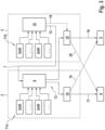
Figur 3 zeigt schematisch den Aufbau der beiden Steuergeräte 2, 3 und der entsprechenden Kommunikationspfade. - In dem zweiten Steuergerät 3 ist eine zweite Arbitrierungseinheit 10 vorgesehen, welche basierend auf den zur Verfügung gestellten Parkbremsanforderungsdaten 11b ermittelt, ob ein EPB-Request (Electronic Parking Brake Request) erforderlich ist, das heißt, ob eine Ansteuerung der Parkbremsaktuatoren 4, 5 erforderlich ist. Als Parkbremsanforderungsdaten 11b werden der zweiten Arbitrierungseinheit 10 zumindest das Signal eines Parkbremsschalters (SAR - Static Apply Release) und ein möglicher externer Parkbremsbefehl (XAR - External Apply Release) zugeführt. Das Ergebnis der zweiten Arbitrierung 12 wird über die Kommunikationsleitung 7 an das erste Steuergerät 2 übermittelt, und dort der ersten Arbitrierungseinheit 9 als Teil derer Parkbremsanforderungsdaten 11a zugeführt.
- Auch der ersten Arbitrierungseinheit 9 werden als Parkbremsanforderungsdaten 11a darüber hinaus zumindest das Signal eines Parkbremsschalters (SAR) und ein möglicher externer Parkbremsbefehl (XAR) zugeführt. Es ist jedoch auch möglich, das Signal des Parkbremsschalters und/oder einen möglichen externen Parkbremsbefehl jeweils nur einer der beiden Arbitrierungseinheiten 9, 10 zuzuführen, da auch in diesem Fall, durch die Hintereinanderschaltung der beiden Arbitrierungseinheiten 9, 10 auf jeden Fall alle Parkbremsanforderungsdaten 11 in Betracht gezogen werden. Die erste Arbitrierungseinheit 9 ermittelt aus sämtlichen Parkbremsanforderungsdaten 11a inklusive des Ergebnisses 12 der zweiten Arbitrierung ob ein EPB-Request erforderlich ist. Dieses Ergebnis wird an den ersten Treiber 14 des ersten Steuergeräts 2 übertragen, welcher ein mechatronisches Subsystem zur Ansteuerung von Parkbremsaktuatoren bildet. Das Ergebnis wird außerdem an den zweiten Treiber 15 des zweiten Steuergeräts 3 übertragen, welcher ebenfalls ein mechatronisches Subsystem zur Ansteuerung von Parkbremsaktuatoren bildet
- In der ersten Ausführungsform der
Figur 1 ist der erste Treiber 14 lediglich über eine Steuerleitung 17 mit dem ersten Parkbremsaktuator 4 verbunden und der zweite Treiber 15 lediglich über eine Steuerleitung 18 mit dem zweiten Parkbremsaktuator 5 verbunden. Die Querverbindungen 19, 20 existieren in dieser Ausführungsform nicht. - Das ermittelte EPB-Request wird somit auf beiden elektronischen Parkbremsaktuatoren 4, 5 ausgeführt.
- Tritt ein Fehler in einem der beiden Steuergeräte 2, 3 auf, so bleibt das System zumindest teilweise funktionsfähig. Bei einem totalen Ausfall des zweiten Steuergeräts 3 empfängt das erste Steuergerät 2 kein Ergebnis 12 der zweiten Arbitrierungseinheit 10 über die Kommunikationsleitung 7. Die erste Arbitrierungseinheit 9 kann jedoch basierend auf den übrigen Parkbremsanforderungsdaten 11a eine Arbitrierung durchführen. Das Ergebnis 13 der Arbitrierung kann auch in diesem Fall zumindest an den Treiber 14 zur Ansteuerung des ersten Parkbremsaktuators 4 übermittelt werden.
- Fällt hingegen das erste Steuergerät 2 aus, so teilt das erste Steuergerät 2 dies dem zweiten Steuergerät 3 über die Kommunikationsleitung 7 mit. Dies kann entweder durch eine explizite Mitteilung stattfinden, oder durch Nichtversenden einer Verfügbarkeitsinformation. Das zweite Steuergerät 3 geht von einem Ausfall des ersten Steuergeräts 2 aus, wenn es keine Verfügbarkeitsinformationen des ersten Steuergeräts 2 über die Kommunikationsleitung 7 erhält. In diesem Fall führt das zweite Steuergerät 3 ebenfalls eine Arbitrierung in der zweiten Arbitrierungseinheit 10 basierend auf den Parkbremsanforderungsdaten 11b durch und übermittelt dieses Ergebnis 12 der Arbitrierung jedoch nicht an das erste Steuergerät 2, sondern gibt das Ergebnis direkt als redundante Parkbremsansteuerung 16 an den Treiber 15 weiter. Der Treiber 15 kann dann zumindest den zweiten Parkbremsaktuator 5 über die Steuerleitung 18 ansteuern. Auch in diesem Fall wird zumindest eine reduzierte Handhaltefähigkeit sichergestellt.
- In der Ausführungsform der
Figur 2 ist das erste Steuergerät 2 mit dem ersten Treiber 14 über eine Steuerleitung 19 zusätzlich mit der zweiten elektronischen Parkbremse und dem zugehörigen Parkbremsaktuator 5 verbunden. Das zweite Steuergerät 3 ist mit dessen Treiber 15 über eine Steuerleitung 20 zusätzlich mit dem ersten Parkbremsaktuator 4 verbunden. Somit kann jeder Parkbremsaktuator 4, 5 von beiden Steuergeräten 2, 3 angesteuert werden, sodass auch bei Ausfall eines der beiden Steuergeräte 4, 5 beide Parkbremsaktuatoren 4, 5 zur Verfügung stehen. - Um zu verhindern, dass ein Parkbremsaktuator 4, 5 gleichzeitig von zwei Treibern 14, 15 angesteuert wird, insbesondere widersprüchlich angesteuert wird, ist vorgesehen, dass nur eines der beiden Steuergeräte 2, 3 die Berechtigung zum tatsächlichen Ansteuern der elektronischen Parkbremsaktuatoren 4, 5 erhält. Bei einer widersprüchlichen Ansteuerung würde ansonsten ein Parkbremsaktuator 4, 5 über den ersten Treiber 14 mit einer ersten Polarität angesteuert werden und über den zweiten Treiber 15 mit entgegengesetzter Polarität. Dadurch würden die beiden Pole der Spannungsversorgung direkt miteinander verbunden werden, wodurch ein Kurzschluss entstünde. Ein solcher Kurzschluss könnte beide Steuergerät gleichzeitig beschädigen und dadurch zu einem Doppelausfall führen. Die Berechtigung wird dabei durch ein austauschbares Token realisiert.
- Die Überprüfung des Tokens kann dabei bereits am Ausgang der ersten Arbitrierungseinheit 9 erfolgen, und die erste Arbitrierungseinheit 9 das Ergebnis 13 der Arbitrierung lediglich an den ersten Treiber 14 übermitteln, wenn das erste Steuergerät 2 selbst das Token besitzt. Besitzt hingegen das zweite Steuergerät 3 das Token, so kann die erste Arbitrierungseinheit 9 das Ergebnis der Arbitrierung 13 lediglich an den zweiten Treiber 15 des zweiten Steuergeräts 3 übermitteln. Alternativ kann das Ergebnis 13 der Arbitrierung von der Arbitrierungseinheit 9 immer an beide Treiber 14, 15 des ersten Steuergeräts 2 bzw. des zweiten Steuergeräts 3 übermittelt werden. Eine Überprüfung, ob das eigene Steuergerät in Besitz des Tokens ist, findet dann erst im Treiber 14, 15 selbst statt. Der Treiber 14, 15 steuert entsprechend die Parkbremsaktuatoren 4, 5 über die Steuerleitung 17, 18, 19, 20 nur dann an, wenn das eigene Steuergerät das Token besitzt.
-
Figur 4 zeigt beispielhaft die Übergabe des Tokens in einem Zeitdiagramm. Sowohl in dem ersten Steuergerät 2 als auch in dem zweiten Steuergerät 3 sind jeweils ein Tokenzustand 21, 22 als binäre Variable implementiert, welche anzeigt, ob das jeweilige Steuergerät das Token besitzt. Der Tokenzustand 21, 22 kann demnach nur die Werte '0' oder '1' annehmen. Zu Beginn bis zum Zeitpunkt t1 besitzt das erste Steuergerät 2 den Token und der Tokenzustand 21 hat demnach den Wert '1'. Das zweite Steuergerät 3 besitzt keinen Token und der Tokenzustand 22 hat daher den Wert ,0'. Zu einem Zeitpunkt t1 stellt das erste Steuergerät 2 einen Fehler fest und übergibt daher das Token an das zweite Steuergerät 3. Dazu setzt das erste Steuergerät 2 den eigenen Tokenzustand 21 auf '0' und sendet eine entsprechende Nachricht über die Kommunikationsleitung 7 an das zweite Steuergerät 3. Zu einem Zeitpunkt t2 empfängt das zweite Steuergerät 3 die entsprechende Nachricht über die Kommunikationsleitung 7 und setzt den eigenen Tokenzustand auf '1'. - Zu einem Zeitpunkt t3 stellt das erste Steuergerät 2 fest, dass es wieder fehlerfrei funktioniert und übernimmt das Token. Das erste Steuergerät 2 setzt daher den eigenen Tokenzustand 21 auf '1' und sendet über den Kommunikationskanal 7 eine entsprechende Nachricht an das zweite Steuergerät 3. Zu einem Zeitpunkt t4 empfängt das zweite Steuergerät 3 die entsprechende Nachricht und setzt den eigenen Tokenzustand 22 auf ,0'. Zwischen dem Zeitpunkt t3 und t4 haben für eine kurze Zeitspanne sowohl der Tokenzustand 21 des ersten Steuergeräts 2 als auch der Tokenzustand 22 des zweiten Steuergeräts 3 den Wert ,1'. Um in diesem Zeitraum einen doppelten Zugriff auf die Parkbremsaktuatoren 4, 5 zu vermeiden, kann ein Treiber 14, 15 nur auf die Parkbremsaktuatoren 4, 5 zugreifen, wenn das eigene Steuergerät 2, 3 den Token hat, d. h. der Tokenzustand 21, 22 den Wert '1' aufweist und der Tokenzustand 21, 22 des jeweils anderen Steuergeräts 2, 3 den Wert ,0' hat. Im Zeitraum zwischen t3 und t4 kann somit keines der Treiber auf die Parkbremsaktuatoren 4, 5 zugreifen.
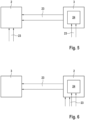
- Um zu vermeiden, dass Parkbremsaktuatoren bei fahrendem Fahrzeug aktiviert werden und somit eine Gefahrensituation hervorrufen können, wird vor dem Anziehen der Parkbremsaktuatoren 4, 5 überprüft, ob sich das Fahrzeug im Stillstand befindet. Dazu werden Raddrehzahlsensordaten 23 verwendet. Um sowohl im ersten Steuergerät als auch im zweiten Steuergerät 3 den Fahrzeugstillstand feststellen zu können, werden zwei Raddrehzahlsensordaten 23 über einen Multiplexer 24 verteilt. Eine entsprechende Architektur ist in
Figur 5 dargestellt, bei der die Raddrehzahlsensordaten zweier Räder des Fahrzeugs direkt an das erste Steuergerät 2 übermittelt werden und die Raddrehzahlsensordaten 23 der übrigen zwei Räder des Fahrzeugs werden direkt an das zweite Steuergerät 3 übermittelt. Das zweite Steuergerät 3 weist einen Multiplexer 24 auf, welcher das Signal der zwei Raddrehzahlsensoren entweder an die entsprechende Recheneinheit des zweiten Steuergeräts 3 übermitteln kann oder an das erste Steuergerät 2 kommuniziert. Dazu kann der Multiplexer 24 eine direkte Verbindung (hard-wired) an das erste Steuergerät 2 aufweisen. An dem ersten Steuergerät 2 liegen dann die Signale der Raddrehzahlsensoren so an, als seien die Raddrehzahlsensoren direkt an das erste Steuergerät 2 angeschlossen. Der Multiplexer 24 ist derart ausgebildet, dass er im stromlosen Fall, also wenn das eigene Steuergerät 2, 3 einen Defekt aufweist, die Raddrehzahldaten an das andere Steuergerät 2, 3 weiterleitet. - Eine alternative Ausführungsform ist in
Figur 6 dargestellt, bei der die Raddrehzahlsignale aller vier Räder zuerst bei dem ersten Steuergerät 2 ankommen. Zwei Raddrehzahlsensoren werden wiederum über den Multiplexer 24 an das zweite Steuergerät 2 weitergeleitet. - In beiden Varianten werden im fehlerfreien Fall dem ersten Steuergerät 2 alle vier Raddrehzahlsensordaten zur Verfügung gestellt, da dieses im fehlerfreien Fall die die eigentliche Ansteuerung der Parkbremsaktuatoren 4, 5 durchführt. Für den selten auftretenden Fehlerfall steht dem zweiten Steuergerät 3 noch zwei Raddrehzahlsensordaten 23 zur Verfügung, um den Stillstand des Fahrzeugs festzustellen.
- Durch die erfindungsgemäße Bremsanlage wird sichergestellt, dass auch im Falle des Ausfalls eines der Steuergeräte zumindest eine reduzierte Handhaltefähigkeit zur Verfügung steht, sodass eine Getriebeklinke nicht mehr nötig ist und daher entfallen kann. Dabei ist sichergestellt, dass es immer einen "single point of decision" gibt, um mögliche Steuerfehler auszuschließen.
-
- 1
- Bremsanlage
- 2
- Erstes Steuergerät
- 3
- Zweites Steuergerät
- 4
- Erstes Parkbremsaktuator
- 5
- Zweiter Parkbremsaktuator
- 6
- Hydraulische Bremseinheit
- 7
- Kommunikationspfad
- 8
- Redundante Hydrauliksteuerung
- 9
- Erste Arbitrierungseinheit
- 10
- Zweite Arbitrierungseinheit
- 11
- a, b erste und zweite Parkbremsanforderungsdaten
- 12
- Arbitrierungsergebnis erste Arbitrierungseinheit
- 13
- Arbitrierungsergebnis zweite Arbitrierungseinheit
- 14
- Erster Treiber
- 15
- Zweiter Treiber
- 16
- Redundante Parkbremsansteuerung
- 17
- Steuerleitung erster Treiber zu erster Parkbremse
- 18
- Steuerleitung zweiter Treiber zu zweiter Parkbremse
- 19
- Steuerleitung erster Treiber zu zweiter Parkbremse
- 20
- Steuerleitung zweiter Treiber zu erster Parkbremse
- 21
- Tokenzustand erstes Steuergerät
- 22
- Tokenzustand zweites Steuergerät
- 23
- Drehzahlsensordaten
- 24
- Multiplexer
- t1
- Zeitpunkt Abgabe Token
- t2
- Zeitpunkt Annahme Token
- t3
- Zeitpunkt Übernahme Token
- t4
- Zeitpunkt Übergabe Token
Claims (15)
- Bremsanlage für ein Kraftfahrzeug aufweisend einen ersten Parkbremsaktuator (4) und einen zweiten Parkbremsaktuator (5) undein erstes Steuergerät (2) und ein zweites Steuergerät (3), welche jeweils einen Treiber (14, 15) zur Ansteuerung zumindest des ersten und/oder des zweiten Parkbremsaktuators (4, 5) aufweisen,wobei das erste Steuergerät (2) eine erste Arbitrierungseinheit (9) aufweist, welche dazu eingerichtet ist erste Parkbremsanforderungsdaten (11a) zu empfangen und aus den empfangenen Parkbremsanforderungsdaten (11a) zu ermitteln, ob eine Parkbremsaktion durchgeführt werden soll,wobei das zweite Steuergerät (3) eine zweite Arbitrierungseinheit (10) aufweist, welche dazu eingerichtet ist zweite Parkbremsanforderungsdaten (11b) zu empfangen und aus den empfangenen Parkbremsanforderungsdaten (11b) zu ermitteln, ob eine Parkbremsaktion durchgeführt werden soll,wobei ein Ergebnis der zweiten Arbitrierungseinheit (10) der ersten Arbitrierungseinheit (9) eingangsseitig als Teil der ersten Parkbremsanforderungsdaten (11a) zugeführt wird undwobei ein Ergebnis der ersten Arbitrierungseinheit (9) an den Treiber (14, 15) des ersten und/oder des zweiten Steuergeräts (2, 3) zur Ansteuerung des ersten und/oderdes zweiten Parkbremsaktuators (4, 5) übermittelt wird.
- Bremsanlage nach Anspruch 1, dadurch gekennzeichnet, dass ein Parkbremsschalter vorgesehen ist, dessen Schaltzustand als Teil der ersten und/oder zweiten Parkbremsanforderungsdaten (11a, 11b) der ersten Arbitrierungseinheit (9) und/oder der zweiten Arbitrierungseinheit (10) zugeführt wird.
- Bremsanlage nach Anspruch 1 oder 2, dadurch gekennzeichnet, dass der Treiber (14) des ersten Steuergeräts (2) nur zur Ansteuerung des ersten Parkbremsaktuators (4) eingerichtet ist und der Treiber (15) des zweiten Steuergeräts (3) nur zur Ansteuerung des zweiten Parkbremsaktuators (5) eingerichtet ist.
- Bremsanlage nach Anspruch 1 oder 2, dadurch gekennzeichnet, dass die Treiber (14, 15) des ersten Steuergeräts (2) und des zweiten Steuergeräts (3) jeweils zur Ansteuerung des ersten und des zweiten Parkbremsaktuators (4, 5) eingerichtet sind.
- Bremsanlage nach einem der vorhergehenden Ansprüche, dadurch gekennzeichnet, dass beide Steuergeräte (2, 3) den Zustand der jeweils zugeordneten Parkbremsaktuatoren (4, 5) bestimmen und den bestimmten Zustand dem jeweils anderen Steuergerät (3, 2) übermitteln, wobei insbesondere im ersten und/oder zweiten Steuergerät (2, 3) die Zustände der beiden Parkbremsaktuatoren (4, 5) zu einem Gesamtzustand kombiniert werden.
- Bremsanlage nach einem der vorhergehenden Ansprüche, dadurch gekennzeichnet, dass das erste Steuergerät (2) und das zweite Steuergerät (3) über eine separate Kommunikationsleitung (7) und/oder über einen Fahrzeugbus miteinander kommunizieren.
- Bremsanlage nach einem der vorhergehenden Ansprüche, dadurch gekennzeichnet, dass das erste Steuergerät (2) und das zweite Steuergerät (3), insbesondere gegenseitig, Verfügbarkeitsinformationen (21, 22) austauschen, wobei das zweite Steuergerät (3) von einem Ausfall des ersten Steuergeräts (2) ausgeht, wenn die Verfügbarkeitsinformation (21, 22) keine Verfügbarkeit anzeigt und/oder keine Verfügbarkeitsinformationen (21, 22) empfangen werden.
- Bremsanlage nach einem der vorhergehenden Ansprüche, dadurch gekennzeichnet, dass die zweite Arbitrierungseinheit (10) dazu eingerichtet ist, bei Ausfall des ersten Steuergeräts (2) das Ergebnis der Arbitrierung an den Treiber (15) des zweiten Steuergeräts (3) zur Ansteuerung des zumindest einen Parkbremsaktuators (5) zu übermitteln.
- Bremsanlage nach einem der vorhergehenden Ansprüche, dadurch gekennzeichnet, dass zumindest ein Parkbremsaktuator (4, 5) mit dem ersten und dem zweiten Steuergerät (2, 3) ansteuerbar verbunden ist, wobei erstes und zweites Steuergerät (2, 3) dazu eingerichtet sind, die Berechtigung zur Ansteuerung des Parkbremsaktuators (4, 5), der mit dem ersten und dem zweiten Steuergerät (2, 3) ansteuerbar verbunden ist, durch Austausch eines Tokens (21, 22) zu übergeben.
- Bremsanlage nach Anspruch 9, dadurch gekennzeichnet, dass bei einem Einschaltvorgang das erste oder das zweite Steuergerät (2, 3) das Token (21, 22) erhält, welches zur Ansteuerung des Parkbremsaktuators (4, 5) der mit dem ersten und dem zweiten Steuergerät (2, 3) ansteuerbar verbunden ist berechtigt, und das andere Steuergerät (3, 2) kein Token (21, 22) erhält.
- Bremsanlage nach Anspruch 9 oder 10, dadurch gekennzeichnet, dass das erste und/oder das zweite Steuergerät (2, 3) dazu eingerichtet sind, nur dann den Parkbremsaktuator (4, 5) anzusteuern, wenn das Steuergerät (2, 3) selbst das Token (21, 22) besitzt und das andere Steuergerät (3, 2) das Token (21, 22) nicht besitzt.
- Bremsanlage nach einem der vorhergehenden Ansprüche, dadurch gekennzeichnet, dass vier Raddrehzahlsensoren (23) vorgesehen sind, die jeweils einem von vier Rädern des Kraftfahrzeugs zugeordnet sind, wobei das erste oder das zweite Steuergerät (2, 3) Daten von allen vier Raddrehzahlsensoren (23) erhält und das andere Steuergerät Daten von nur zwei Raddrehzahlsensoren (23) erhält.
- Bremsanlage nach Anspruch 12, dadurch gekennzeichnet, dass das ein Multiplexer (24) für die Daten von zwei Raddrehzahlsensoren (23) vorgesehen ist, welcher im fehlerfreien Fall die Daten der zwei Raddrehzahlsensoren (23) dem Steuergerät (2, 3) zuführt, welches Daten von allen vier Raddrehzahlsensoren (23) erhält, und nur bei Ausfall dieses Steuergeräts (2, 3) die Daten der zwei Raddrehzahlsensoren (23) dem Steuergerät (2, 3) zuführt, welches Daten von nur zwei Raddrehzahlsensoren (23) erhält.
- Bremsanlage nach Anspruch 13, dadurch gekennzeichnet, dass das die zwei Raddrehzahlsensoren (23) des Multiplexers (24) diagonal zueinander angeordneten Rädern zugeordnet sind.
- Verfahren zur Regelung einer Bremsanlage (1) mit zwei Parkbremsaktuatoren (4, 5) und zwei Steuergeräten (2, 3), wobei eine erste Arbitrierungseinheit (9) des ersten Steuergeräts (2) erste Parkbremsanforderungsdaten (11a) empfängt und aus den empfangenen ersten Parkbremsanforderungsdaten (11a) ermittelt, ob eine Parkbremsaktion durchgeführt werden soll,und eine zweite Arbitrierungseinheit (10) des zweiten Steuergeräts (3) zweite Parkbremsanforderungsdaten (11b) empfängt und aus den empfangenen zweiten Parkbremsanforderungsdaten (11b) ermittelt, ob eine Parkbremsaktion durchgeführt werden soll,wobei ein Ergebnis der zweiten Arbitrierungseinheit (10) der ersten Arbitrierungseinheit (9) eingangsseitig als Teil der ersten Parkbremsanforderungsdaten (11a) zugeführt wird undwobei ein Ergebnis der ersten Arbitrierungseinheit (9) an einen Treiber (14, 15) des ersten und/oder des zweiten Steuergeräts (2, 3) zur Ansteuerung des ersten und/oderdes zweiten Parkbremsaktuators (4, 5) übermittelt wird.
Applications Claiming Priority (2)
| Application Number | Priority Date | Filing Date | Title |
|---|---|---|---|
| DE102020202919.9A DE102020202919A1 (de) | 2020-03-06 | 2020-03-06 | Bremsanlage mit redundanter Parkbremsenansteuerung |
| PCT/DE2021/200026 WO2021175385A1 (de) | 2020-03-06 | 2021-03-01 | Bremsanlage mit redundanter parkbremsenansteuerung |
Publications (2)
| Publication Number | Publication Date |
|---|---|
| EP4114696A1 EP4114696A1 (de) | 2023-01-11 |
| EP4114696B1 true EP4114696B1 (de) | 2025-02-26 |
Family
ID=74884776
Family Applications (1)
| Application Number | Title | Priority Date | Filing Date |
|---|---|---|---|
| EP21712418.9A Active EP4114696B1 (de) | 2020-03-06 | 2021-03-01 | Bremsanlage mit redundanter parkbremsenansteuerung |
Country Status (6)
| Country | Link |
|---|---|
| US (1) | US20230126121A1 (de) |
| EP (1) | EP4114696B1 (de) |
| KR (1) | KR102769990B1 (de) |
| CN (1) | CN115210119B (de) |
| DE (1) | DE102020202919A1 (de) |
| WO (1) | WO2021175385A1 (de) |
Families Citing this family (8)
| Publication number | Priority date | Publication date | Assignee | Title |
|---|---|---|---|---|
| DE102020202920A1 (de) * | 2020-03-06 | 2021-09-09 | Continental Teves Ag & Co. Ohg | Bremsanlage mit redundanter Parkbremsfunktion |
| KR102794446B1 (ko) | 2020-12-17 | 2025-04-14 | 에이치엘만도 주식회사 | 전자식 주차 브레이크 시스템의 모터 구동회로 |
| CN113696876A (zh) * | 2021-09-23 | 2021-11-26 | 广州小鹏汽车科技有限公司 | 车辆驻车控制方法、控制装置、控制系统及车辆 |
| DE102022206480A1 (de) * | 2022-06-28 | 2023-12-28 | Zf Friedrichshafen Ag | Steuern einer Parkbremse für ein Kraftfahrzeug |
| DE102022209494A1 (de) * | 2022-09-12 | 2024-03-14 | Robert Bosch Gesellschaft mit beschränkter Haftung | Verfahren zum Betreiben eines Steuergeräts für ein Parkbremsensystem |
| US12434677B2 (en) | 2023-08-29 | 2025-10-07 | Bendix Commercial Vehicle Systems Llc | Redundant parking brake apparatus for a vehicle and method of operating the same |
| DE102024109516A1 (de) * | 2024-04-05 | 2025-10-09 | Kb Intellectual Property Gmbh & Co. Kg | Vorrichtung und Verfahren zum Bereitstellen von Sensordaten |
| JP2026067131A (ja) * | 2024-10-08 | 2026-04-20 | 株式会社アドヴィックス | 制動制御システム |
Citations (1)
| Publication number | Priority date | Publication date | Assignee | Title |
|---|---|---|---|---|
| EP3529117B1 (de) * | 2016-10-20 | 2020-12-02 | ZF Active Safety GmbH | System mit getrennten steuereinheiten für die stelleinheiten einer elektrischen parkbremse |
Family Cites Families (29)
| Publication number | Priority date | Publication date | Assignee | Title |
|---|---|---|---|---|
| DE19521175C1 (de) | 1995-06-10 | 1996-07-11 | Continental Ag | Elektrisch regelbares Bremssystem |
| US6213567B1 (en) * | 1998-02-02 | 2001-04-10 | Siemens Aktiengesellschaft | Brake system for a motor vehicle and method for transmitting data in an electrically controlled brake system for a motor vehicle |
| DE10006656C1 (de) | 2000-02-15 | 2001-06-07 | Siemens Ag | Feststellbremsanlage für Kraftfahrzeuge |
| DE10118263A1 (de) | 2001-04-12 | 2002-10-17 | Bosch Gmbh Robert | Elektronisches Steuersystem, insbesondere für eine Fahrzeugbremsanlage |
| DE102004017544A1 (de) | 2003-04-11 | 2004-10-21 | Asmo Co., Ltd., Kosai | Elektrisches Feststellbremssystem |
| DE102007029632A1 (de) * | 2006-06-27 | 2008-01-10 | Continental Teves Ag & Co. Ohg | Feststellbremsanlage für Kraftfahrzeuge |
| DE102006053617A1 (de) * | 2006-11-14 | 2008-05-15 | Siemens Ag | System zur Aktorsteuerung, insbesondere Bremssystem |
| DE102007036259A1 (de) * | 2007-08-02 | 2009-02-05 | Robert Bosch Gmbh | Bremssystem für ein Fahrzeug und ein Verfahren zum Betreiben eines Bremssystems für ein Fahrzeug |
| GB0802212D0 (en) * | 2008-02-06 | 2008-03-12 | Meritor Heavy Vehicle Braking | A brake system and method |
| DE102011084534A1 (de) * | 2010-10-18 | 2012-04-19 | Continental Teves Ag & Co. Ohg | Fehlersichere Parkbremse für Kraftfahrzeuge |
| DE102012212329A1 (de) * | 2012-07-13 | 2014-04-03 | Continental Teves Ag & Co. Ohg | Verfahren zum Sicherstellen einer Bremswirkung |
| DE102014006613A1 (de) * | 2014-05-08 | 2015-11-12 | Wabco Gmbh | Steuergerät für ein druckluftbetriebenes Bremssystem, Bremssystem mit derartigem Steuergerät sowie Fahrzeug mit derartigem Bremssystem |
| US10286891B2 (en) * | 2014-07-11 | 2019-05-14 | Ford Global Technologies, Llc | Vehicle parking system failure management |
| US9776607B2 (en) | 2015-01-28 | 2017-10-03 | Continental Automotive Systems, Inc. | Fault-tolerant redundant by-wire brake system |
| CN106926833A (zh) * | 2015-12-30 | 2017-07-07 | 大陆泰密克汽车系统(上海)有限公司 | 一种液压辅助驻车制动系统及具有该系统的车辆 |
| DE102016210984A1 (de) * | 2016-06-20 | 2017-12-21 | Robert Bosch Gmbh | Verfahren zum Betreiben eines Steuergeräts |
| DE102016015544A1 (de) * | 2016-12-27 | 2018-06-28 | Lucas Automotive Gmbh | Kraftfahrzeug-Steuergerät für eine elektrische Parkbremse |
| US10239531B2 (en) * | 2017-01-10 | 2019-03-26 | GM Global Technology Operations LLC | Fault-tolerant automotive braking system |
| DE102017001657A1 (de) * | 2017-02-21 | 2018-08-23 | Lucas Automotive Gmbh | Zugriffsgeschützte Ansteuerung eines Aktuators einer elektrischen Parkbremse |
| DE102017204157A1 (de) * | 2017-03-14 | 2018-09-20 | Bayerische Motoren Werke Aktiengesellschaft | Bremsregelsystem einer elektrohydraulischen Bremsanlage |
| DE102017003650A1 (de) * | 2017-04-13 | 2018-10-18 | Lucas Automotive Gmbh | Hydraulische Kraftfahrzeug-Bremsanlage und Steuergerätesystem hierfür |
| WO2018192717A1 (de) * | 2017-04-19 | 2018-10-25 | Robert Bosch Gmbh | Fahrzeug-feststellbremse |
| DE102017209314A1 (de) * | 2017-06-01 | 2018-12-06 | Robert Bosch Gmbh | Verfahren zum Betreiben einer Feststellbremse und Steuereinheit zum Betreiben einer Feststellbremse |
| CN107757593A (zh) * | 2017-09-22 | 2018-03-06 | 芜湖伯特利汽车安全系统股份有限公司 | 一种具有冗余驻车功能的电子驻车控制系统及其控制方法 |
| CN207416810U (zh) * | 2017-11-16 | 2018-05-29 | 湖北航天技术研究院特种车辆技术中心 | 车辆驻车控制设备以及用于车辆驻车的安全保护装置 |
| DE102018002990B4 (de) * | 2018-04-12 | 2025-10-09 | Zf Active Safety Gmbh | Hydraulische Kraftfahrzeug-Bremsanlage und Verfahren zum Betreiben derselben |
| CN209870362U (zh) * | 2019-02-03 | 2019-12-31 | 上海蔚来汽车有限公司 | 电子驻车系统、包括该电子驻车系统的车辆 |
| KR102173984B1 (ko) * | 2019-06-27 | 2020-11-05 | 현대모비스 주식회사 | 자율주행 차량의 브레이크 제어 장치 |
| US11488404B2 (en) * | 2019-10-14 | 2022-11-01 | Ford Global Technologies, Llc | Session unique access token for communications with a vehicle |
-
2020
- 2020-03-06 DE DE102020202919.9A patent/DE102020202919A1/de active Pending
-
2021
- 2021-03-01 KR KR1020227026932A patent/KR102769990B1/ko active Active
- 2021-03-01 US US17/905,507 patent/US20230126121A1/en active Pending
- 2021-03-01 EP EP21712418.9A patent/EP4114696B1/de active Active
- 2021-03-01 CN CN202180017652.4A patent/CN115210119B/zh active Active
- 2021-03-01 WO PCT/DE2021/200026 patent/WO2021175385A1/de not_active Ceased
Patent Citations (1)
| Publication number | Priority date | Publication date | Assignee | Title |
|---|---|---|---|---|
| EP3529117B1 (de) * | 2016-10-20 | 2020-12-02 | ZF Active Safety GmbH | System mit getrennten steuereinheiten für die stelleinheiten einer elektrischen parkbremse |
Also Published As
| Publication number | Publication date |
|---|---|
| CN115210119A (zh) | 2022-10-18 |
| DE102020202919A1 (de) | 2021-09-09 |
| KR102769990B1 (ko) | 2025-02-18 |
| EP4114696A1 (de) | 2023-01-11 |
| CN115210119B (zh) | 2024-09-06 |
| KR20220119493A (ko) | 2022-08-29 |
| WO2021175385A1 (de) | 2021-09-10 |
| US20230126121A1 (en) | 2023-04-27 |
Similar Documents
| Publication | Publication Date | Title |
|---|---|---|
| EP4114697B1 (de) | Bremsanlage mit redundanter parkbremsfunktion | |
| EP4114696A1 (de) | Bremsanlage mit redundanter parkbremsenansteuerung | |
| EP2183136B1 (de) | Bremssystem für ein fahrzeug und ein verfahren zum betreiben eines bremssystems für ein fahrzeug | |
| EP2229302B2 (de) | Bremsanlage für ein fahrzeug sowie bremspedaleinrichtung für eine derartige bremsanlage | |
| DE102017222484B4 (de) | Verfahren und Vorrichtung für eine hochverfügbare automatische Parkbremse | |
| EP3265350B1 (de) | Steuergerät und verfahren für ein kraftfahrzeugbremssystem | |
| DE102008024180A1 (de) | Kombinierte Bremsanlage, insbesondere für Kraftfahrzeuge | |
| EP1819567B2 (de) | Elektromechanische Feststell-Bremsanlage und elektronisches System zum betreiben derselben | |
| DE102017217856A1 (de) | Bremssystem für ein Kraftfahrzeug und Verfahren zum Betreiben eines Bremssystems | |
| DE102013020177A1 (de) | Kraftfahrzeug | |
| DE10144797A1 (de) | Verfahren sowie Regel- und Steuerungssystem zur Einstellung autonomer Fahrfunktionen in einem Fahrzeug | |
| EP2038150A1 (de) | Feststellbremsanlage für kraftfahrzeuge | |
| EP3583008B1 (de) | Verfahren und fahrzeugsteuergerät für ein autonomes fahrzeug und fahrzeug | |
| EP2183133A1 (de) | Feststellbremsanlage und verfahren zum betreiben einer solchen | |
| DE102020107548A1 (de) | Kraftfahrzeug und Verfahren zum Betreiben eines Kraftfahrzeugs | |
| EP0830998B1 (de) | Elektrische Bremsanlage und Verfahren zum Betreiben einer elektrischen Bremsanlage | |
| DE102012219533A1 (de) | Bremsanlage für Kraftfahrzeuge | |
| DE102018001866A1 (de) | Verfahren zum automatischen Abbremsen eines sich während eines automatischen fahrerlosen Parkvorganges bewegenden Fahrzeuges | |
| DE102018125308A1 (de) | Feststellbremse eines zweispurigen Fahrzeuges und Verfahren zum Betreiben einer Festellbremse | |
| DE102021209798B4 (de) | Steuerungssystem für eine elektromechanische Aktivierung einer Bremswirkung bei einem Fahrzeug sowie Fahrzeug | |
| WO2023198257A1 (de) | Bremssystem und verfahren zum betreiben eines bremssystems | |
| DE102022106986A1 (de) | Verfahren zum Betrieb eines Bremssystems eines Fahrzeugs und Fahrzeugsteuerungssystem zum Steuern autonomer Parkvorgänge | |
| DE102021209799A1 (de) | Steuerungssystem für eine elektromechanische Aktivierung einer Bremswirkung bei einem Fahrzeug, Fahrzeug, Verfahren sowie Computerprogrammprodukt | |
| EP1743820B1 (de) | Steuervorrichtung zum Ansteuern eines Stellantriebs | |
| DE102023203065A1 (de) | Verfahren zur Steuerung einer Parkbremseinrichtung einer elektrohydraulischen Bremsanlage und elektrohydraulische Bremsanlage |
Legal Events
| Date | Code | Title | Description |
|---|---|---|---|
| STAA | Information on the status of an ep patent application or granted ep patent |
Free format text: STATUS: UNKNOWN |
|
| STAA | Information on the status of an ep patent application or granted ep patent |
Free format text: STATUS: THE INTERNATIONAL PUBLICATION HAS BEEN MADE |
|
| PUAI | Public reference made under article 153(3) epc to a published international application that has entered the european phase |
Free format text: ORIGINAL CODE: 0009012 |
|
| STAA | Information on the status of an ep patent application or granted ep patent |
Free format text: STATUS: REQUEST FOR EXAMINATION WAS MADE |
|
| 17P | Request for examination filed |
Effective date: 20221006 |
|
| AK | Designated contracting states |
Kind code of ref document: A1 Designated state(s): AL AT BE BG CH CY CZ DE DK EE ES FI FR GB GR HR HU IE IS IT LI LT LU LV MC MK MT NL NO PL PT RO RS SE SI SK SM TR |
|
| DAV | Request for validation of the european patent (deleted) | ||
| DAX | Request for extension of the european patent (deleted) | ||
| RAP3 | Party data changed (applicant data changed or rights of an application transferred) |
Owner name: CONTINENTAL AUTOMOTIVE TECHNOLOGIES GMBH |
|
| GRAP | Despatch of communication of intention to grant a patent |
Free format text: ORIGINAL CODE: EPIDOSNIGR1 |
|
| STAA | Information on the status of an ep patent application or granted ep patent |
Free format text: STATUS: GRANT OF PATENT IS INTENDED |
|
| INTG | Intention to grant announced |
Effective date: 20241014 |
|
| GRAS | Grant fee paid |
Free format text: ORIGINAL CODE: EPIDOSNIGR3 |
|
| GRAA | (expected) grant |
Free format text: ORIGINAL CODE: 0009210 |
|
| STAA | Information on the status of an ep patent application or granted ep patent |
Free format text: STATUS: THE PATENT HAS BEEN GRANTED |
|
| AK | Designated contracting states |
Kind code of ref document: B1 Designated state(s): AL AT BE BG CH CY CZ DE DK EE ES FI FR GB GR HR HU IE IS IT LI LT LU LV MC MK MT NL NO PL PT RO RS SE SI SK SM TR |
|
| REG | Reference to a national code |
Ref country code: GB Ref legal event code: FG4D Free format text: NOT ENGLISH |
|
| REG | Reference to a national code |
Ref country code: CH Ref legal event code: EP |
|
| REG | Reference to a national code |
Ref country code: DE Ref legal event code: R096 Ref document number: 502021006784 Country of ref document: DE |
|
| REG | Reference to a national code |
Ref country code: IE Ref legal event code: FG4D Free format text: LANGUAGE OF EP DOCUMENT: GERMAN |
|
| PGFP | Annual fee paid to national office [announced via postgrant information from national office to epo] |
Ref country code: DE Payment date: 20250331 Year of fee payment: 5 |
|
| PGFP | Annual fee paid to national office [announced via postgrant information from national office to epo] |
Ref country code: AT Payment date: 20250417 Year of fee payment: 5 |
|
| REG | Reference to a national code |
Ref country code: NL Ref legal event code: MP Effective date: 20250226 |
|
| PG25 | Lapsed in a contracting state [announced via postgrant information from national office to epo] |
Ref country code: RS Free format text: LAPSE BECAUSE OF FAILURE TO SUBMIT A TRANSLATION OF THE DESCRIPTION OR TO PAY THE FEE WITHIN THE PRESCRIBED TIME-LIMIT Effective date: 20250526 |
|
| PG25 | Lapsed in a contracting state [announced via postgrant information from national office to epo] |
Ref country code: FI Free format text: LAPSE BECAUSE OF FAILURE TO SUBMIT A TRANSLATION OF THE DESCRIPTION OR TO PAY THE FEE WITHIN THE PRESCRIBED TIME-LIMIT Effective date: 20250226 |
|
| PG25 | Lapsed in a contracting state [announced via postgrant information from national office to epo] |
Ref country code: PL Free format text: LAPSE BECAUSE OF FAILURE TO SUBMIT A TRANSLATION OF THE DESCRIPTION OR TO PAY THE FEE WITHIN THE PRESCRIBED TIME-LIMIT Effective date: 20250226 |
|
| PG25 | Lapsed in a contracting state [announced via postgrant information from national office to epo] |
Ref country code: ES Free format text: LAPSE BECAUSE OF FAILURE TO SUBMIT A TRANSLATION OF THE DESCRIPTION OR TO PAY THE FEE WITHIN THE PRESCRIBED TIME-LIMIT Effective date: 20250226 |
|
| REG | Reference to a national code |
Ref country code: LT Ref legal event code: MG9D |
|
| PG25 | Lapsed in a contracting state [announced via postgrant information from national office to epo] |
Ref country code: NO Free format text: LAPSE BECAUSE OF FAILURE TO SUBMIT A TRANSLATION OF THE DESCRIPTION OR TO PAY THE FEE WITHIN THE PRESCRIBED TIME-LIMIT Effective date: 20250526 Ref country code: IS Free format text: LAPSE BECAUSE OF FAILURE TO SUBMIT A TRANSLATION OF THE DESCRIPTION OR TO PAY THE FEE WITHIN THE PRESCRIBED TIME-LIMIT Effective date: 20250626 |
|
| PG25 | Lapsed in a contracting state [announced via postgrant information from national office to epo] |
Ref country code: NL Free format text: LAPSE BECAUSE OF FAILURE TO SUBMIT A TRANSLATION OF THE DESCRIPTION OR TO PAY THE FEE WITHIN THE PRESCRIBED TIME-LIMIT Effective date: 20250226 |
|
| PG25 | Lapsed in a contracting state [announced via postgrant information from national office to epo] |
Ref country code: HR Free format text: LAPSE BECAUSE OF FAILURE TO SUBMIT A TRANSLATION OF THE DESCRIPTION OR TO PAY THE FEE WITHIN THE PRESCRIBED TIME-LIMIT Effective date: 20250226 |
|
| PG25 | Lapsed in a contracting state [announced via postgrant information from national office to epo] |
Ref country code: PT Free format text: LAPSE BECAUSE OF FAILURE TO SUBMIT A TRANSLATION OF THE DESCRIPTION OR TO PAY THE FEE WITHIN THE PRESCRIBED TIME-LIMIT Effective date: 20250626 Ref country code: LV Free format text: LAPSE BECAUSE OF FAILURE TO SUBMIT A TRANSLATION OF THE DESCRIPTION OR TO PAY THE FEE WITHIN THE PRESCRIBED TIME-LIMIT Effective date: 20250226 |
|
| PG25 | Lapsed in a contracting state [announced via postgrant information from national office to epo] |
Ref country code: BG Free format text: LAPSE BECAUSE OF FAILURE TO SUBMIT A TRANSLATION OF THE DESCRIPTION OR TO PAY THE FEE WITHIN THE PRESCRIBED TIME-LIMIT Effective date: 20250226 Ref country code: GR Free format text: LAPSE BECAUSE OF FAILURE TO SUBMIT A TRANSLATION OF THE DESCRIPTION OR TO PAY THE FEE WITHIN THE PRESCRIBED TIME-LIMIT Effective date: 20250527 |
|
| PG25 | Lapsed in a contracting state [announced via postgrant information from national office to epo] |
Ref country code: SE Free format text: LAPSE BECAUSE OF FAILURE TO SUBMIT A TRANSLATION OF THE DESCRIPTION OR TO PAY THE FEE WITHIN THE PRESCRIBED TIME-LIMIT Effective date: 20250226 |
|
| PG25 | Lapsed in a contracting state [announced via postgrant information from national office to epo] |
Ref country code: SM Free format text: LAPSE BECAUSE OF FAILURE TO SUBMIT A TRANSLATION OF THE DESCRIPTION OR TO PAY THE FEE WITHIN THE PRESCRIBED TIME-LIMIT Effective date: 20250226 |
|
| PG25 | Lapsed in a contracting state [announced via postgrant information from national office to epo] |
Ref country code: DK Free format text: LAPSE BECAUSE OF FAILURE TO SUBMIT A TRANSLATION OF THE DESCRIPTION OR TO PAY THE FEE WITHIN THE PRESCRIBED TIME-LIMIT Effective date: 20250226 |
|
| PG25 | Lapsed in a contracting state [announced via postgrant information from national office to epo] |
Ref country code: IT Free format text: LAPSE BECAUSE OF FAILURE TO SUBMIT A TRANSLATION OF THE DESCRIPTION OR TO PAY THE FEE WITHIN THE PRESCRIBED TIME-LIMIT Effective date: 20250226 |
|
| PG25 | Lapsed in a contracting state [announced via postgrant information from national office to epo] |
Ref country code: EE Free format text: LAPSE BECAUSE OF FAILURE TO SUBMIT A TRANSLATION OF THE DESCRIPTION OR TO PAY THE FEE WITHIN THE PRESCRIBED TIME-LIMIT Effective date: 20250226 Ref country code: CZ Free format text: LAPSE BECAUSE OF FAILURE TO SUBMIT A TRANSLATION OF THE DESCRIPTION OR TO PAY THE FEE WITHIN THE PRESCRIBED TIME-LIMIT Effective date: 20250226 |
|
| REG | Reference to a national code |
Ref country code: CH Ref legal event code: W10 Free format text: ST27 STATUS EVENT CODE: U-0-0-W10-W00 (AS PROVIDED BY THE NATIONAL OFFICE) Effective date: 20251022 |
|
| REG | Reference to a national code |
Ref country code: CH Ref legal event code: H13 Free format text: ST27 STATUS EVENT CODE: U-0-0-H10-H13 (AS PROVIDED BY THE NATIONAL OFFICE) Effective date: 20251023 |
|
| PG25 | Lapsed in a contracting state [announced via postgrant information from national office to epo] |
Ref country code: RO Free format text: LAPSE BECAUSE OF FAILURE TO SUBMIT A TRANSLATION OF THE DESCRIPTION OR TO PAY THE FEE WITHIN THE PRESCRIBED TIME-LIMIT Effective date: 20250226 |
|
| PG25 | Lapsed in a contracting state [announced via postgrant information from national office to epo] |
Ref country code: SK Free format text: LAPSE BECAUSE OF FAILURE TO SUBMIT A TRANSLATION OF THE DESCRIPTION OR TO PAY THE FEE WITHIN THE PRESCRIBED TIME-LIMIT Effective date: 20250226 |
|
| PG25 | Lapsed in a contracting state [announced via postgrant information from national office to epo] |
Ref country code: LU Free format text: LAPSE BECAUSE OF NON-PAYMENT OF DUE FEES Effective date: 20250301 |
|
| RAP4 | Party data changed (patent owner data changed or rights of a patent transferred) |
Owner name: AUMOVIO GERMANY GMBH |
|
| REG | Reference to a national code |
Ref country code: DE Ref legal event code: R097 Ref document number: 502021006784 Country of ref document: DE |
|
| REG | Reference to a national code |
Ref country code: BE Ref legal event code: MM Effective date: 20250331 |
|
| PG25 | Lapsed in a contracting state [announced via postgrant information from national office to epo] |
Ref country code: MC Free format text: LAPSE BECAUSE OF FAILURE TO SUBMIT A TRANSLATION OF THE DESCRIPTION OR TO PAY THE FEE WITHIN THE PRESCRIBED TIME-LIMIT Effective date: 20250226 |
|
| PLBE | No opposition filed within time limit |
Free format text: ORIGINAL CODE: 0009261 |
|
| STAA | Information on the status of an ep patent application or granted ep patent |
Free format text: STATUS: NO OPPOSITION FILED WITHIN TIME LIMIT |
|
| PG25 | Lapsed in a contracting state [announced via postgrant information from national office to epo] |
Ref country code: BE Free format text: LAPSE BECAUSE OF NON-PAYMENT OF DUE FEES Effective date: 20250331 |
|
| PG25 | Lapsed in a contracting state [announced via postgrant information from national office to epo] |
Ref country code: CH Free format text: LAPSE BECAUSE OF NON-PAYMENT OF DUE FEES Effective date: 20250331 |
|
| PG25 | Lapsed in a contracting state [announced via postgrant information from national office to epo] |
Ref country code: IE Free format text: LAPSE BECAUSE OF NON-PAYMENT OF DUE FEES Effective date: 20250301 |
|
| REG | Reference to a national code |
Ref country code: DE Ref legal event code: R081 Ref document number: 502021006784 Country of ref document: DE Owner name: AUMOVIO GERMANY GMBH, DE Free format text: FORMER OWNER: CONTINENTAL AUTOMOTIVE TECHNOLOGIES GMBH, 30175 HANNOVER, DE |
|
| GBPC | Gb: european patent ceased through non-payment of renewal fee |
Effective date: 20250526 |
|
| 26N | No opposition filed |
Effective date: 20251127 |
|
| PG25 | Lapsed in a contracting state [announced via postgrant information from national office to epo] |
Ref country code: GB Free format text: LAPSE BECAUSE OF NON-PAYMENT OF DUE FEES Effective date: 20250526 |
|
| PGFP | Annual fee paid to national office [announced via postgrant information from national office to epo] |
Ref country code: FR Payment date: 20260323 Year of fee payment: 6 |