EP4113786A1 - Verfahren, gerät und ladegerät - Google Patents
Verfahren, gerät und ladegerät Download PDFInfo
- Publication number
- EP4113786A1 EP4113786A1 EP22181016.1A EP22181016A EP4113786A1 EP 4113786 A1 EP4113786 A1 EP 4113786A1 EP 22181016 A EP22181016 A EP 22181016A EP 4113786 A1 EP4113786 A1 EP 4113786A1
- Authority
- EP
- European Patent Office
- Prior art keywords
- voltage
- charging
- charger
- converter
- state
- Prior art date
- Legal status (The legal status is an assumption and is not a legal conclusion. Google has not performed a legal analysis and makes no representation as to the accuracy of the status listed.)
- Pending
Links
Images




Classifications
-
- H—ELECTRICITY
- H04—ELECTRIC COMMUNICATION TECHNIQUE
- H04R—LOUDSPEAKERS, MICROPHONES, GRAMOPHONE PICK-UPS OR LIKE ACOUSTIC ELECTROMECHANICAL TRANSDUCERS; ELECTRIC HEARING AIDS; PUBLIC ADDRESS SYSTEMS
- H04R25/00—Electric hearing aids
- H04R25/30—Monitoring or testing of hearing aids, e.g. functioning, settings, battery power
-
- H—ELECTRICITY
- H02—GENERATION; CONVERSION OR DISTRIBUTION OF ELECTRIC POWER
- H02J—ELECTRIC POWER NETWORKS; CIRCUIT ARRANGEMENTS OR SYSTEMS FOR SUPPLYING OR DISTRIBUTING ELECTRIC POWER; SYSTEMS FOR STORING ELECTRIC ENERGY
- H02J7/00—Circuit arrangements for charging or discharging batteries or for supplying loads from batteries
-
- H—ELECTRICITY
- H02—GENERATION; CONVERSION OR DISTRIBUTION OF ELECTRIC POWER
- H02J—ELECTRIC POWER NETWORKS; CIRCUIT ARRANGEMENTS OR SYSTEMS FOR SUPPLYING OR DISTRIBUTING ELECTRIC POWER; SYSTEMS FOR STORING ELECTRIC ENERGY
- H02J50/00—Circuit arrangements or systems for wireless supply or distribution of electric power
- H02J50/10—Circuit arrangements or systems for wireless supply or distribution of electric power using inductive coupling
-
- H—ELECTRICITY
- H02—GENERATION; CONVERSION OR DISTRIBUTION OF ELECTRIC POWER
- H02J—ELECTRIC POWER NETWORKS; CIRCUIT ARRANGEMENTS OR SYSTEMS FOR SUPPLYING OR DISTRIBUTING ELECTRIC POWER; SYSTEMS FOR STORING ELECTRIC ENERGY
- H02J50/00—Circuit arrangements or systems for wireless supply or distribution of electric power
- H02J50/80—Circuit arrangements or systems for wireless supply or distribution of electric power involving the exchange of data, concerning supply or distribution of electric power, between transmitting devices and receiving devices
-
- H—ELECTRICITY
- H02—GENERATION; CONVERSION OR DISTRIBUTION OF ELECTRIC POWER
- H02J—ELECTRIC POWER NETWORKS; CIRCUIT ARRANGEMENTS OR SYSTEMS FOR SUPPLYING OR DISTRIBUTING ELECTRIC POWER; SYSTEMS FOR STORING ELECTRIC ENERGY
- H02J7/00—Circuit arrangements for charging or discharging batteries or for supplying loads from batteries
- H02J7/40—Circuit arrangements for charging or discharging batteries or for supplying loads from batteries characterised by the exchange of charge or discharge related data
-
- H—ELECTRICITY
- H02—GENERATION; CONVERSION OR DISTRIBUTION OF ELECTRIC POWER
- H02J—ELECTRIC POWER NETWORKS; CIRCUIT ARRANGEMENTS OR SYSTEMS FOR SUPPLYING OR DISTRIBUTING ELECTRIC POWER; SYSTEMS FOR STORING ELECTRIC ENERGY
- H02J7/00—Circuit arrangements for charging or discharging batteries or for supplying loads from batteries
- H02J7/40—Circuit arrangements for charging or discharging batteries or for supplying loads from batteries characterised by the exchange of charge or discharge related data
- H02J7/42—Circuit arrangements for charging or discharging batteries or for supplying loads from batteries characterised by the exchange of charge or discharge related data with electronic devices having internal batteries, e.g. mobile phones
-
- H—ELECTRICITY
- H02—GENERATION; CONVERSION OR DISTRIBUTION OF ELECTRIC POWER
- H02J—ELECTRIC POWER NETWORKS; CIRCUIT ARRANGEMENTS OR SYSTEMS FOR SUPPLYING OR DISTRIBUTING ELECTRIC POWER; SYSTEMS FOR STORING ELECTRIC ENERGY
- H02J7/00—Circuit arrangements for charging or discharging batteries or for supplying loads from batteries
- H02J7/485—Circuit arrangements for charging or discharging batteries or for supplying loads from batteries with provisions for charging different types of batteries
-
- H—ELECTRICITY
- H02—GENERATION; CONVERSION OR DISTRIBUTION OF ELECTRIC POWER
- H02J—ELECTRIC POWER NETWORKS; CIRCUIT ARRANGEMENTS OR SYSTEMS FOR SUPPLYING OR DISTRIBUTING ELECTRIC POWER; SYSTEMS FOR STORING ELECTRIC ENERGY
- H02J7/00—Circuit arrangements for charging or discharging batteries or for supplying loads from batteries
- H02J7/50—Circuit arrangements for charging or discharging batteries or for supplying loads from batteries acting upon multiple batteries simultaneously or sequentially
-
- H—ELECTRICITY
- H02—GENERATION; CONVERSION OR DISTRIBUTION OF ELECTRIC POWER
- H02J—ELECTRIC POWER NETWORKS; CIRCUIT ARRANGEMENTS OR SYSTEMS FOR SUPPLYING OR DISTRIBUTING ELECTRIC POWER; SYSTEMS FOR STORING ELECTRIC ENERGY
- H02J7/00—Circuit arrangements for charging or discharging batteries or for supplying loads from batteries
- H02J7/60—Circuit arrangements for charging or discharging batteries or for supplying loads from batteries including safety or protection arrangements
- H02J7/62—Circuit arrangements for charging or discharging batteries or for supplying loads from batteries including safety or protection arrangements against overcurrent
-
- H—ELECTRICITY
- H02—GENERATION; CONVERSION OR DISTRIBUTION OF ELECTRIC POWER
- H02J—ELECTRIC POWER NETWORKS; CIRCUIT ARRANGEMENTS OR SYSTEMS FOR SUPPLYING OR DISTRIBUTING ELECTRIC POWER; SYSTEMS FOR STORING ELECTRIC ENERGY
- H02J7/00—Circuit arrangements for charging or discharging batteries or for supplying loads from batteries
- H02J7/60—Circuit arrangements for charging or discharging batteries or for supplying loads from batteries including safety or protection arrangements
- H02J7/64—Circuit arrangements for charging or discharging batteries or for supplying loads from batteries including safety or protection arrangements against overvoltage
-
- H—ELECTRICITY
- H02—GENERATION; CONVERSION OR DISTRIBUTION OF ELECTRIC POWER
- H02J—ELECTRIC POWER NETWORKS; CIRCUIT ARRANGEMENTS OR SYSTEMS FOR SUPPLYING OR DISTRIBUTING ELECTRIC POWER; SYSTEMS FOR STORING ELECTRIC ENERGY
- H02J7/00—Circuit arrangements for charging or discharging batteries or for supplying loads from batteries
- H02J7/60—Circuit arrangements for charging or discharging batteries or for supplying loads from batteries including safety or protection arrangements
- H02J7/663—Circuit arrangements for charging or discharging batteries or for supplying loads from batteries including safety or protection arrangements using battery or load disconnect circuits
-
- H—ELECTRICITY
- H02—GENERATION; CONVERSION OR DISTRIBUTION OF ELECTRIC POWER
- H02J—ELECTRIC POWER NETWORKS; CIRCUIT ARRANGEMENTS OR SYSTEMS FOR SUPPLYING OR DISTRIBUTING ELECTRIC POWER; SYSTEMS FOR STORING ELECTRIC ENERGY
- H02J7/00—Circuit arrangements for charging or discharging batteries or for supplying loads from batteries
- H02J7/90—Regulation of charging or discharging current or voltage
-
- H—ELECTRICITY
- H02—GENERATION; CONVERSION OR DISTRIBUTION OF ELECTRIC POWER
- H02J—ELECTRIC POWER NETWORKS; CIRCUIT ARRANGEMENTS OR SYSTEMS FOR SUPPLYING OR DISTRIBUTING ELECTRIC POWER; SYSTEMS FOR STORING ELECTRIC ENERGY
- H02J7/00—Circuit arrangements for charging or discharging batteries or for supplying loads from batteries
- H02J7/90—Regulation of charging or discharging current or voltage
- H02J7/96—Regulation of charging or discharging current or voltage in response to battery voltage
-
- H—ELECTRICITY
- H04—ELECTRIC COMMUNICATION TECHNIQUE
- H04R—LOUDSPEAKERS, MICROPHONES, GRAMOPHONE PICK-UPS OR LIKE ACOUSTIC ELECTROMECHANICAL TRANSDUCERS; ELECTRIC HEARING AIDS; PUBLIC ADDRESS SYSTEMS
- H04R25/00—Electric hearing aids
- H04R25/55—Electric hearing aids using an external connection, either wireless or wired
- H04R25/554—Electric hearing aids using an external connection, either wireless or wired using a wireless connection, e.g. between microphone and amplifier or using Tcoils
-
- H—ELECTRICITY
- H04—ELECTRIC COMMUNICATION TECHNIQUE
- H04R—LOUDSPEAKERS, MICROPHONES, GRAMOPHONE PICK-UPS OR LIKE ACOUSTIC ELECTROMECHANICAL TRANSDUCERS; ELECTRIC HEARING AIDS; PUBLIC ADDRESS SYSTEMS
- H04R2225/00—Details of deaf aids covered by H04R25/00, not provided for in any of its subgroups
- H04R2225/31—Aspects of the use of accumulators in hearing aids, e.g. rechargeable batteries or fuel cells
Definitions
- the invention relates to a method, a device and a charger.
- “device” is understood to mean a mobile device, the device is therefore generally transportable and has its own energy store for supplying energy.
- the device is regularly assigned to a single user and, if necessary, even individually tailored to this user.
- the energy store is usually a secondary cell (e.g. lithium battery), which can be charged by connecting the mobile device to a charger.
- the device is connected to the charger in a contact-based or wireless manner in order to transfer energy from the charger to the device and then to charge the device, more precisely its energy store, with this energy.
- a specific example of a device is a hearing device, which is used to care for a user who has a hearing deficit.
- the hearing device has a microphone that picks up sound from the environment and generates an electrical input signal.
- This is supplied to a signal processing system of the hearing aid for modification.
- the modification takes place in particular using an individual audiogram of the user, so that an individual hearing deficit of the user is compensated.
- the signal processing outputs an electrical output signal, which is then converted back into sound via a receiver of the hearing aid and is output to the user.
- other input and/or output converters are also possible instead of the microphone and the receiver.
- the hearing device is binaural or monaural, ie for use on both sides or just one side of the user's head.
- devices are headphones, headsets, wearables, smartphones, and similar devices.
- the device During charging, the device is in a charging state. After charging, and although the device is still connected to the charger, the device typically turns on and enters a discharge state, or the charger continues to transfer energy to prevent a transition to the discharge state. In both cases, energy is disadvantageously consumed.
- a device is connected to a charging device and wireless charging takes place in a charging state, in that energy is transmitted wirelessly to a receiving module of the device using a transmission module of the charging device.
- the device is switched off and is in the charging state.
- the device has a charging connection, to which a charging voltage V cc is applied for charging, which can be set with the charging device.
- the device also has a switching connection for switching the device on and off.
- the charging port and the switch port are preferably ports of a power management module (also referred to as PMIC) of the device.
- the energy management module accepts the charging voltage and uses it to charge an energy store, eg a lithium battery, of the device.
- the device also has a discharge state in which energy is consumed, namely by one or more consumers of the device.
- the energy management module controls the provision of energy for the consumers from the device's energy store.
- the device thus receives energy from the charger, in the discharging state the device consumes energy.
- the device is necessarily connected to the charger, in the discharging state, the device is either disconnected from the charger or connected to it.
- the device is switched on is understood to mean that the consumers are supplied with energy, in particular by means of the energy management module, and "the device is switched off” is then understood to mean that the consumers are not supplied with energy, although the energy management module can continue to consume energy.
- the discharge state the device is also switched on due to the principle. When it is described below that the device is "turned off”, it is understood that firstly, if the device is switched on, “is switched off”, and secondly, if the device is already switched off, “remains switched off”.
- the device also has a switch which is connected to the switching terminal and which can be switched with the charging voltage by setting the charging voltage to an intermediate voltage.
- the switch is part of a switch-off circuit of the device.
- the charger adjusts the charging voltage to the intermediate voltage so that the switch is switched and the device enters an off state in which the device is switched off.
- the device is (ie is or remains) switched off by means of the charger, in that the charger adjusts the charging voltage to the intermediate voltage, so that the switch is switched and the device changes to an off state.
- This ie the setting of the intermediate voltage and the subsequent change to the off state, takes place in particular when charging is terminated or interrupted, but can in principle also take place generally in the event of a fault, for example when the energy store overheats or overvoltages/overcurrents.
- the charger thus initiates a switch of the device to the off state, in which the device then - unlike in the discharge state - no longer consumes any energy.
- the charger uses the option of setting the charging voltage variably.
- the automatic switch-off thus advantageously saves energy after charging, since the device is switched off and therefore does not change to the discharging state.
- the device is a mobile device and therefore generally transportable.
- the device is regularly assigned to a single user and, if necessary, even individually tailored to this user.
- the energy store is usually a secondary cell (e.g. lithium battery), which can be charged by connecting the device to the charger.
- the device is preferably a hearing device, which is used to supply a user who has/have a hearing deficit.
- the hearing device has a microphone that picks up sound from the environment and generates an electrical input signal. This is supplied to a signal processing system of the hearing aid for modification. The modification takes place in particular using an individual audiogram of the user, so that an individual hearing deficit of the user is compensated.
- the signal processing outputs an electrical output signal, which is then converted back into sound via a receiver of the hearing aid and is output to the user.
- other input and/or output converters are also possible instead of the microphone and the receiver.
- the hearing device is binaural or monaural, ie for use on both sides or just one side of the user's head. Input converters (e.g. microphone), output converters (e.g. earpiece), signal processing are consumers of the device.
- the device is a headphone, headset, wearable, smartphone or the like.
- the device is connected to the charging device and suitably inserted, used or placed on it for this purpose.
- the charger is designed as a charging cradle with a recess into which the device can be inserted.
- the charger has a lid to close the charger, covering the cavity so that the device is entirely enclosed within the charger.
- the recess is expediently shaped in such a way that the device is held therein in an arrangement that is as defined as possible relative to the charging cradle.
- the energy store Depending on the charge of the energy store, i.e. how fully charged the energy store is, it provides a voltage V bat for one or more loads, which may also be transformed beforehand with a transformation unit, e.g. in the energy management module, so that this then generates a voltage V out to consumers. Typically, the greater the charge, the greater this voltage.
- the device is charged by the charger with a charging voltage V cc (ie “charging input voltage”), the charging voltage being the voltage that is present in the device for charging the energy store. The energy store is then charged until the desired charge or voltage is reached.
- V cc ie "charging input voltage”
- a charging threshold voltage V chg,thres (ie “charging threshold voltage”) is suitably specified, which is compared with the charging voltage in order to determine when charging takes place and when not. Charging is preferably ended when the charging voltage falls below the charging threshold voltage.
- the charging threshold voltage is, for example, a permanently specified voltage.
- an automatic switch-off In order to turn off the device (ie the device turns off or remains off) after it has been fully charged, an automatic switch-off (ie "automatic switch-off") is advantageous.
- the automatic switch-off is carried out by the device itself, but is not initiated by it itself, but from the charger, so that the automatic switch-off is more precisely an "externally initiated automatic switch-off".
- the charger determines when to turn off the device and then sends an off signal to the device to turn it off.
- the switch-off signal means that the intermediate voltage is present in the device. Without an automatic switch-off, the device would be switched on continuously even after charging and energy would be consumed, in particular at least by the energy management module for its operation.
- one specification requires that a BLE (Bluetooth Low Energy) function of the device is turned off and thus the device does not operate in a pairing mode or an offering mode as long as the device is connected to the charger and as long as there is no explicit user input to turn it on of the BLE function.
- the pairing mode the specification therefore requires that the device should not be able to be paired with another device while it is connected to the charger.
- the offer mode the specification then requires that the device should not emit a ready signal (indicating its readiness for pairing) to other devices while connected to the charger.
- a first such scenario is a power failure in which an energy supply of the charger is interrupted.
- a second scenario is removing a power cable of the charger, where the cable connects the charger to a power grid, eg via a domestic socket. The second scenario is basically similar to the first scenario.
- a third scenario is that an energy store of a portable charger is completely discharged, so that the charger can no longer provide energy for charging the device. In all of these scenarios, no more energy is transferred to the device and therefore the device typically enters the discharge state. As a result, the device is on instead of off. Accordingly, energy-consuming functions, such as the BLE function, are also switched on.
- the charging connection is an electrical contact, for example a contact pin, via which the device is connected to the charging device for charging and is therefore also galvanically coupled in the case of contact-based charging.
- the charging voltage is present at the charging connection, so the charging connection is generally a power contact.
- the switching connection is also designed as a contact pin, for example. In particular, the switching connection is pulled up with a pull-up resistor. A switch that can be actuated manually is expediently connected between the switching connection and ground for manually switching off the device.
- the device then has the above-mentioned switch-off circuit with switch, which uses the charging connection and the switching connection, for automatic switching off by means of the charging device.
- the switch is preferably a transistor, with a gate, source and drain, ie with corresponding connections.
- the terms gate, drain and source are used here and below for designation of the three terminals of the transistor is used. However, the statements generally apply to any switch with three terminals, which are functionally equivalent to the gate, source and drain of a transistor.
- the gate of the transistor is pulled up to the charge voltage with the charge terminal and with a resistor of the turn-off circuit.
- the resistor connects the gate to the source and to ground.
- the drain and source of the transistor are connected to the switching terminal and to ground, respectively.
- an additional operating state for the device is advantageously realized with the automatic switch-off, namely the off state in which the device is connected to the charging device but is switched off and thus neither consumes energy itself nor receives energy from the charger.
- the device is switched off in the charging state, but still receives energy (in particular for operating the energy management module), and switched on in the discharging state and consumes energy.
- the device also has a waiting state (i.e. "idle state"), so that a total of four operating states are possible, which in particular are mutually exclusive.
- the device preferably changes from the discharging state, the off state or the waiting state to the charging state when the charging voltage is at least equal to the charging threshold voltage. As long as the charging voltage is at least equal to the charging threshold voltage, the state of charge remains active.
- the device changes from charging state to waiting state when the charging voltage is lower than the charging threshold voltage.
- the device changes from the waiting state to the discharging state when the charging voltage is lower than a reset voltage V rst and in addition in particular when a time has also elapsed which is longer than a discharging time t disc .
- the reset voltage is, for example, a permanently specified voltage and in particular a parameter of the energy management module.
- the reset voltage is used in particular to ensure the operation of the To stop the energy management module and to initialize it to a predefined standard state by applying a voltage to the energy management module which corresponds at least to the reset voltage. This initialization then enables proper operation subsequently.
- the reset voltage is also used in particular to determine when to switch from the waiting state to the discharge state.
- the discharge time is, for example, a fixed predetermined time of a few seconds.
- the device changes from the discharging state to the waiting state when the charging voltage is less than the charging threshold voltage and greater than the reset voltage, and from the waiting state to the charging state when the charging voltage is at least the charging threshold voltage. As long as the charge voltage is less than the charge threshold voltage, the wait state remains active.
- the automatic switching off ie a change to the off state, is now realized by setting the charging voltage at the charging connection to an intermediate voltage which is a gate-source threshold voltage V gs-thres of the transistor and expediently between the reset voltage and a minimum gate-source threshold voltage, ie a minimum value for the gate-source threshold voltage.
- the gate-source threshold voltage is the voltage required to switch (in particular turn on) the transistor and is in particular in a range between the minimum gate-source threshold voltage (the voltage which is at least required to switch the transistor) and a gate -Maximum source threshold voltage (the maximum voltage that is possible to switch the transistor).
- the reset voltage is greater than the gate-source threshold voltage actually used, but the maximum gate-source threshold voltage may be greater than the reset voltage.
- the transistor expediently has the greatest possible difference between the minimum gate-source threshold voltage and the maximum gate-source threshold voltage. For example, the maximum gate-source threshold voltage is 20V.
- the device will enter the discharging state.
- the discharge state is initially active as long as the charging voltage is lower than the minimum gate-source threshold voltage.
- the device then enters the off-state when the charging voltage is less than the reset voltage and greater than the charging threshold voltage, and in addition in particular when a time (during which the intermediate voltage is held) has elapsed, which is longer than one Switch port active time t sca .
- the transistor is switched and the switching connection is pulled to ground.
- the device briefly enters the discharge state and from there into the off state, especially after the switching terminal active time.
- the switching connection active time is, for example, a fixed predetermined time of, for example, a few seconds.
- a change to the off state is preferably only possible starting from the discharge state.
- the device changes from the off state to the charging state when the charging voltage is at least equal to the charging threshold voltage.
- the device has a switch, e.g. a button, button, slide switch or the like.
- the solution described for automatically switching off the device is easily possible with contact-based charging, since there is a galvanic connection via which the intermediate voltage can be set in a simple manner. Since the charging voltage is provided directly by the charger, the intermediate voltage can be easily adjusted accordingly. In the case of a charger for wireless charging, however, this is not readily possible since the charging voltage is not provided directly by the charger, but is merely induced in the device and thus in the charger by means of the transmitter module itself is not necessarily present.
- the charger without an automatic switch-off, the charger must continuously transfer energy to the device in order to prevent the discharge state from being activated, and if the energy supply is interrupted, the device would regularly be automatically put into the discharge state, possibly with an activated wait state in between, as described above.
- a starting point of the present invention is now, in particular, to implement the off state as described specifically for a charging device for wireless charging, that is to say not in a contact-based manner but wirelessly.
- the previous statements apply to both contact-based and wireless charging.
- the energy is transferred from the charger to the device using a transmitter module in the charger and a receiver module in the device.
- energy is preferably transmitted by means of a magnetic field, which is generated with a transmitting coil of the transmitting module and which is received with a receiving coil of the receiving module.
- the transmission module is controlled in such a way that the intermediate voltage is induced in the device.
- An important advantage of the present invention is in particular that the device is switched off wirelessly with the charger.
- the charging voltage is adjusted to the intermediate voltage with the magnetic field of the charger, so that the device switches to the off state.
- a wireless automatic switch-off is thus implemented by means of a magnetic field.
- the magnetic field otherwise used for charging thus also represents the switch-off signal, which is sent from the charger to the device, when controlled accordingly.
- the device and the charger are suitably designed.
- the magnetic field in the charger which generally induces the charging voltage in the device, is changed in such a way that the intermediate voltage is generated.
- the off state is automatically activated when the device is fully charged or the charger is no longer providing energy (see the various scenarios above), so that the device is then switched off and is not consuming any energy.
- the wireless automatic Switching off is also advantageous because, compared to contact-based automatic switching off, this allows the device and the charging device to be arranged more freely relative to one another, at least within the limits in which energy can still be transferred for charging.
- the charger and the wireless charging device together form a wireless charging system.
- the device also has the already mentioned receiving module and one or more consumers.
- the loads are operated with energy from the energy store in the discharge state. Examples of loads are a BLE module that provides a BLE function, a signal processing unit or electroacoustic loads, e.g. an earpiece or a microphone.
- the receiving module provides the charging voltage and outputs it to the energy management module.
- the receiving module is designed to receive energy from the charging device, which correspondingly has the already mentioned transmission module for sending the energy.
- the transmission module has a transmission coil for transmitting energy
- the reception module has a reception coil analogously for receiving the energy.
- the transmitter coil is generally powered by a power source from the charger.
- the receiving module expediently has wiring for the receiving coil in order to generate the charging voltage.
- the wiring has, for example, a tuning capacitor, a smoothing capacitor and a Schottky diode.
- the charging voltage V cc is typically dependent on a large number of parameters, in particular the current I tx to the transmitter coil, the respective inductance of the transmitter coil Ltx and the receiver coil L rx , a transmission frequency f , which is used to transmit the energy using the magnetic field, and a coupling factor k.
- the coupling factor in turn depends in particular on the distance and the angle of inclination between the transmitting coil and the receiving coil, ie generally on the spatial arrangement of the charging device and the device when charging. The smaller the distance and the smaller the tilt angle, the larger the coupling factor.
- the general rule for the charging voltage is: V cc ⁇ 2 ⁇ ⁇ f k ⁇ (L tx L rx ) I tx . This makes it particularly clear that the charging voltage that is actually present in the device depends on a number of parameters (transmission frequency, inductance of the transmitter coil, current for operating the transmitter coil) of the charger and can be manipulated accordingly by the latter.
- the switch-off circuit for the wireless automatic switch-off is basically designed as for the contact-based automatic switch-off.
- the switch-off circuit has a switch, preferably a transistor, which is switched (in particular switched on) by the intermediate voltage.
- the transistor of the turn-off circuit is preferably a MOSFET.
- the resistance connecting the gate and source of the transistor is suitably of high value, for example 100 k ⁇ and generally preferably between 10 k ⁇ and 1 M ⁇ .
- the gate is pulled up to the charging voltage from the receiving module.
- the drain is connected to the switching terminal of the power management module and the source is connected to ground. In this way, as already described, four operating states are made possible, including the off state.
- the charging device suitably also has a converter and an oscillator for wireless energy transfer.
- the oscillator generates a current to operate the transmitter coil and is therefore a current source.
- the transmitter coil and the oscillator then form the transmitter module.
- the oscillator is, for example, an inverter or power amplifier and generally generates a current (ie alternating current) for generating the magnetic field with the transmitter module.
- the converter on the other hand, generates a converter voltage to operate the oscillator. The converter thus influences the current with which the transmission coil is operated.
- the charging voltage and thus specifically also the intermediate voltage is thus adjusted by means of the converter voltage.
- the converter is preferably a step-down converter (also referred to as a step-down converter or "buck converter”), which is designed to convert an input voltage into an output voltage that is reduced in comparison, namely the converter voltage.
- the converter is in particular connected or connectable to an energy source for the charger, for example with an energy store of the charger or with a power grid outside of the charger.
- the charging voltage increases linearly with an increasing coupling factor on the one hand and with an increasing current to the transmitter coil on the other.
- These two relationships namely between charging voltage and coupling factor on the one hand and between charging voltage and current on the other hand, are advantageously used in the present case in order to control the charging voltage in the device using the current to the transmitter coil in the charger when the coupling factor is known, and thus to activate the off state in a targeted manner.
- the converter voltage from the converter in the charger controls the oscillator, which in turn controls the current to the transmitter coil.
- the current to the transmission coil can first be adjusted and then ultimately also the charging voltage in the device, which can also be adjusted to the intermediate voltage in this way.
- the device's off state is then activated externally by the charger by suitably controlling the converter and setting its converter voltage.
- the relationship between the converter voltage V dd and the charging voltage V cc is as described above by V cc ⁇ 2 ⁇ ⁇ f ⁇ k ⁇ ⁇ (L tx ⁇ L rx ) ⁇ I tx , where the current I tx is a function of the converter voltage V dd as described , suitably the current is proportional to the converter voltage.
- the converter voltage that is to be set in order to generate a specific charging voltage and in particular the intermediate voltage is dependent on the coupling factor between the transmitting module and the receiving module and can vary in principle.
- the inductances and the transmission frequency are known for a given charging system due to the principle involved.
- the transmission frequency is preferably between 3 MHz and 30 MHz and is 13.56 MHz, for example.
- the converter voltage and thus also the current are therefore set in order to generate the intermediate voltage, by first determining the coupling factor and then using this to determine that converter voltage which is required is used to generate the intermediate voltage.
- the coupling factor is suitably also determined via the relationship between the charging voltage and the current/converter voltage, but now with a known pair of values for the charging voltage V cc and the current I tx . Since the charging voltage is not known to the charger, communication between the charger and the device is advantageous for determining the coupling factor.
- the device sends the last charging voltage that was still present during charging (more precisely: its value) to the charger. This last charging voltage still present is also referred to as the "final charging voltage". In particular, the final charge voltage is greater than the reset voltage and the gate-source threshold voltage.
- the charger stores the current (more precisely: its value) that is used to operate the transmitter coil at the time of the final charging voltage, ie the last current that was still present during charging, which is analogously referred to as the final current.
- the final charge voltage is sent over a data link between the device and the charger.
- the device and the charging device each have a communication unit, for example an antenna and a suitable circuit for the antenna, for sending and/or receiving data, specifically the final charging voltage.
- the charger receives the final charging voltage, whereupon the coupling factor is then determined in combination with the final current, in particular using the relationship mentioned.
- the converter voltage of the converter is then determined with the intended intermediate voltage and the coupling factor. Since the intermediate voltage is in a voltage range between the reset voltage and the minimum gate-source threshold voltage, this also applies to the converter voltage then a suitable voltage range, from which the converter voltage is then selected, eg simply the mean value of the voltage range.
- the setting of the converter voltage thus preferably includes the following four steps: In a first step, a final current and a final charging voltage are determined. Then, in a second step, the coupling factor is determined based on the final current and the final charging voltage. Then, in a third step, the converter voltage required for this is determined using the coupling factor and the intended intermediate voltage. Finally, this converter voltage is adjusted in a fourth step.
- the relationship used to determine the coupling factor and the converter voltage is stored in a memory of the charging device, for example as a function or as a table.
- the relationship V cc ⁇ 2 ⁇ ⁇ f ⁇ k ⁇ ⁇ (L tx ⁇ L rx ) ⁇ I tx (V dd ) is stored for this as a parameterized function bundle.
- the charging voltage is stored in particular as a function of the coupling factor and is parameterized with the current, resulting in a corresponding function bundle.
- the charging voltage is stored in particular as a function of the converter voltage and parameterized with the coupling factor, so that a corresponding function bundle results.
- the final charging voltage is 7.6 V, for example, and the associated final current is 0.5 A, for example.
- the converter voltage is then set to 0.2 V, for example, so that the corresponding intermediate voltage results in the device and the device switches to the off state, initiated wirelessly by the charger.
- a respective transistor is only suitable, in particular, if its gate-source threshold voltage is lower than the reset voltage, at least in some areas; other transistors, on the other hand, are unsuitable for the switch-off circuit.
- a suitable transistor has a minimum gate-source threshold voltage of less than 2 V, e.g. 1.4 V or 0.7 V.
- the reset voltage defines an upper limit for the converter voltage for all distances, because this must not exceed the value that causes the reset voltage to be exceeded in the device (for the sake of simplicity, we speak of the distance here, but the statements generally apply to the coupling constant).
- the upper limit for the converter voltage is 0.69 V, for example. If this cannot be maintained, automatic switch-off may not be possible for certain distances.
- the distance between the transmitting coil and the receiving coil is suitably between 1 mm and 10 mm for charging. In order to enable automatic turn-off for all distances, the charge voltage must be above the gate-source threshold voltage at each distance. For those distances for which this condition is not met, automatic switching off is not possible.
- the distance between the transmitting coil and the receiving coil is 4 mm.
- the device first switches to charging status and is being charged.
- the converter voltage of the converter is then set to 0.6 V for automatic switch-off.
- the charging voltage in the device is thus set to an intermediate voltage of 1.5 V.
- the device first switches to the discharge state and a few seconds later begins to consume energy, for which the energy management module provides a voltage of e.g. 1.3 V to the consumers. Then the device switches to the off state. After a few seconds (e.g. ⁇ 6 s), the converter voltage is then set to 0 V in order to switch off the converter.
- the charger can now be switched off altogether and disconnected from the device, the device then remains in the off state without switching back to the discharge state, even though the charging voltage is then 0 V.
- the coupling factor is expediently determined for automatically switching off the device, the actual spatial arrangement of the device and charging device is also automatically taken into account, so that switching off is advantageously largely independent of this arrangement. A high degree of freedom in the arrangement is thus possible without compromising the automatic switch-off function.
- the automatic switch-off is initiated by the charger using its magnetic field.
- automatic Switching off wirelessly ie without a galvanic connection between device and charger
- automatic switch-off is initially more complicated because the intermediate voltage cannot simply be set by the charger, as this is only generated indirectly via the magnetic field and is also dependent on the coupling constant.
- the solution described here for wireless automatic switch-off therefore differs from the solution for contact-based automatic switch-off in particular on the one hand by the design of the charger, specifically its hardware in general and its converter and communication unit in particular, and on the other hand by the design of the device, especially its switch the turn-off circuit.
- the charging device is initially designed for wireless charging and preferably not for contact-based charging.
- a contact module with corresponding electrical contacts, e.g. contact pins or pogo pins, for the transmission of energy is not necessary and is preferably absent.
- the charging device has a transmission module for energy transfer and also a communication unit for data exchange with the device.
- the antenna of the communication unit is, for example, spiral and/or helix-shaped and designed as a wire or conductor track.
- the device and the charging device therefore each preferably have a communication unit for exchanging data.
- the communication unit of the charger forms a communication system for data exchange with the communication unit of the device.
- the communication system is used in particular at least to transmit data, in particular relating to the charging voltage, from the device to the charging device.
- the communication system can be bidirectional or only monodirectional from the device to the charger.
- the communication system is preferably wireless and uses an appropriate communication protocol, for example magnetic induction in a communication frequency band in the MHz range for the transmission of data.
- the transmission of data occurs either within (ie "in-band”) of the communication frequency band, eg by means of amplitude modulation, or outside (ie “out-of-band”) of the communication frequency band, eg by means of frequency modulation or phase shift keying (ie “phase-shift keying”).
- the data is modulated in particular by the device for transmission (also referred to as “load modulation”).
- the charger receives the data and in particular demodulates it (also referred to as "load demodulation").
- the charging device suitably has a demodulator circuit for demodulation.
- the current in the transmission module is also determined with the demodulator circuit, more precisely the current through the transmission coil, which is integrated into the demodulator circuit for this purpose.
- the demodulator circuit suitably has a capacitor at which the current results as a ratio of a maximum object detection voltage of the demodulator circuit and its impedance at the transmission frequency of the transmission coil.
- LDO low dropout regulator
- buck converter a buck converter in the case of a contact-based automatic switch-off and outputs a voltage between the reset voltage and the minimum gate-source threshold voltage as the converter voltage in order to turn off the device.
- this voltage range for the converter voltage is not necessarily applicable to wireless automatic switch-off, since in this case a lower converter voltage is typically required for switch-off.
- the conversion voltage of the converter is an input voltage for the oscillator.
- the oscillator is in particular a power amplifier.
- the converter voltage is a DC voltage and the oscillator then converts the converter voltage into an AC voltage to produce the current for the transmitter coil in AC accordingly.
- the oscillator also amplifies the converter voltage of the converter, so that in the device ultimately results in a correspondingly larger charging voltage, especially when the receiving coil has more turns than the transmitting coil. If the charging voltage is too high, especially higher than the reset voltage, then the device changes to the charging state or the waiting state, but not to the off state, which is now no longer accessible.
- the converter voltage of the converter is therefore significantly lower in the case of wireless automatic switch-off than in the case of contact-bound automatic switch-off and is suitably in the millivolt range, ie in particular at least 1 mV and in any case less than 0.6 V.
- the converter is typically not able to generate a converter voltage below a converter-internal feedback reference voltage (“feedback reference voltage”), which is regularly at least 0.6 V. Therefore, in a preferred embodiment, the charging device has a voltage reference circuit in addition to the converter, in order to generate a converter voltage overall below the feedback reference voltage of the converter.
- the voltage reference circuit has a reference voltage which is external to the converter and is connected to a feedback connection of the converter. The external reference voltage is greater than the internal feedback reference voltage.
- the voltage reference circuit is then designed and connected to the converter in such a way that the converter voltage V dd results from the difference between the internal feedback reference voltage V fb on the one hand and the difference between the external reference voltage V ref and the internal feedback weighted with a suitable resistance ratio R1/R2 of two resistors -Reference voltage V fb on the other hand.
- V dd V fb - R1 * (V ref - V fb )/R2.
- the two resistors form a voltage divider, with two end points to which an output of the converter on the one hand and the external reference voltage on the other hand are connected, and with a middle point between the two resistors to which the feedback connection is connected.
- the switch of the switch-off circuit of the device is - as described above - preferably a transistor, especially a MOSFET. With regard to the voltages involved, this is preferably designed as described below.
- the Gate-source maximum threshold voltage is suitably as large as possible to avoid damage if charging voltage is too high accidentally or in case of failure. For example, it is possible that the charging voltage fluctuates when charging starts and is not yet stable, or that the charging voltage overshoots due to external interference.
- the gate-source maximum threshold voltage suitably corresponds to at least the maximum possible charging voltage.
- the gate-source threshold voltage which is also referred to in particular as the switch-on voltage, is also of importance.
- the gate-source threshold voltage is suitably lower than the reset voltage, allowing the device to go into the discharge state and from there to the off state.
- the greater the voltage range between the minimum gate-source threshold voltage and the reset voltage the greater the number of different spatial arrangements (distance and angle of inclination) of the device and charger relative to one another that automatic switch-off is possible. Therefore, a gate-source threshold voltage that is as low as possible is preferred.
- the charge voltage must drop to an intermediate voltage in the voltage range between the minimum gate-source threshold voltage and the reset voltage.
- the voltage range between the minimum gate-source threshold voltage and the reset voltage preferably has a width of at least 1 V.
- the charger comprises a control unit to which the communication unit and the converter are connected.
- the converter is adjusted by means of the control unit, namely based on the data which was received by means of the communication unit.
- the charger expediently has an emergency energy store so that if the power supply to the charger is interrupted (cf. above scenarios), the intermediate voltage can still be set and the switch-off signal generated for this purpose and thus the device still switched to the switch off state. If the power supply to the charger is interrupted, there is spontaneously no more energy available to operate the charger, so that it can no longer generate a switch-off signal for the device. Due to the emergency energy store, however, an energy source is available apart from the regular energy supply by cable or energy store, which at least briefly still provides enough energy to generate the switch-off signal.
- the emergency energy store is in particular designed separately from an energy store, which may be present in the charger for charging the device.
- the emergency energy store is correspondingly small.
- the emergency energy storage is suitably a battery or a supercapacitor.
- the switch-off circuit in combination with the communication system implements an advantageous method in which, initiated by the charger, the device is switched off automatically and wirelessly, in particular at the end of charging the energy store of the device and generally when the energy transmission from the charger to the device is interrupted Device.
- the method preferably has one or more of the following steps, preferably in the order mentioned.
- the device sends data to the charger, preferably on a recurring basis.
- the data is analyzed, eg by the control unit. If the data are modulated, they are demodulated beforehand in the second step, for example using the demodulator circuit described.
- the converter is adjusted based on the data, in particular from the control unit.
- DAC digital analog converter
- PWM pulse width modulation
- the converter then outputs a converter voltage to the oscillator and thereby controls it.
- the oscillator emits a current with which the transmitter coil is then operated. The current is thus set indirectly by the converter in the fourth step.
- the transmitter coil generates a magnetic field depending on the current.
- the magnetic field is received by the receiving coil, which generates a charging voltage depending on it generated in the device, so that overall the charger induces a charging voltage in the device.
- a seventh step the device is then switched off if the charging voltage is in the voltage range between the reset voltage and the minimum gate-source threshold voltage, ie if the charging voltage is an intermediate voltage as described. If an intermediate voltage is present, the device changes to the off state in the seventh step and is then switched off.
- the device preferably only changes to the off state when, as described, a time has also elapsed that is longer than a switching connection active time.
- the automatic switch-off takes place depending on the data that the device sends to the charger.
- the converter is switched off, preferably a certain time, for example 10 s, after the device has switched to the off state. This prevents the converter from consuming any more energy.
- the data then contain at least the final charging voltage, which is determined in connection with the final current and is also used in combination with this, in particular by the control unit, to determine a suitable converter voltage and then set the converter in accordance with the above statements.
- events other than the end of charging are basically also suitable for initiating the automatic switch-off, e.g. if the temperature of the energy storage device exceeds a limit temperature (overheating), if the voltage or current at the energy storage device exceeds a corresponding limit value (overvoltage/overcurrent), generally at an error in the energy storage device (error), or similar events.
- the control unit then infers one or more of these events when the control unit analyzes the data and then controls the converter accordingly to initiate the automatic switch-off.
- a device 2 and a charger 4 are shown, which are suitable for carrying out the method described here.
- the device 2 is connected to the charging device 4 and wireless charging takes place in a charge state LZ, in that energy is transmitted wirelessly to a receiving module 8 of the device 2 using a transmitting module 6 of the charging device 4 .
- Device 2 is in 1 is an example of a binaural hearing aid with two individual devices, so that there are two receiving modules 8, which are supplied by the transmitting module 6 of the charger.
- an equivalent circuit diagram for the device 2 and the charger 4 is shown in 3 then again another representation of the device 2 and the charger 4. In 4 only the device 2 is shown.
- the 2 , 3 and 4 are opposite the 1 simplified in that only one receiving module 8 and one transmitting module 6 are shown, ie only one of the individual devices.
- the following statements generally apply regardless of the number of transmitter modules 6 and receiver modules 8, i.e. depending on the design of the device 2 and the charger 4, one or more receiver modules 8 can be present and, independently of this, one or more transmitter modules 6.
- the device 2 When charging, the device 2 is switched off and is in the charge state LZ.
- the device 2 has a charging connection 10 to which a charging voltage V cc is applied for charging, which can be set with the charging device 4 .
- the device 2 also has a switching connection 12 for switching on and off.
- the charging connection 10 and the switching connection 12 are here connections of an energy management module 14 (also referred to as PMIC), which receives the charging voltage V cc and thus charges an energy store 16 of the device 2 .
- PMIC energy management module
- the device 2 also has a discharge state EZ, in which energy is consumed, namely by one or more consumers 18.
- the energy management module 14 controls the provision of energy for the consumers 18 from the energy store 16.
- the device receives 2 thus energy from the charger 4, in the discharge state EZ the device consumes 2 energy.
- the device 2 is switched on is understood to mean that the consumers 18 are supplied with energy by means of the energy management module 14, and "the device 2 is switched off” is then understood to mean that the consumers 18 are not supplied with energy, although the energy management module can 14 continue to consume energy.
- the discharge state EZ the device 2 is also switched on in principle. If it is described below that the device 2 "is switched off”, this means that the device 2 firstly, if it is switched on, “is switched off”, and secondly, if the device 2 is already switched off, “remains switched off”.
- the device 2 also has a switch 20 which is connected to the switching terminal 12 and which can be switched with the charging voltage V cc by setting the charging voltage V cc to an intermediate voltage.
- the switch 20 is part of a switch-off circuit 22.
- the device 2 is now switched off by means of the charger 4 by setting the charging voltage V cc to the intermediate voltage, so that the switch 20 is switched and the device 2 is in an off state AZ changes.
- the charger 4 thus sets the intermediate voltage, whereupon the device 2 switches to the off state AZ. This occurs, for example, when charging is terminated or interrupted, but can also generally occur in the event of a fault, for example if the energy storage device 16 overheats or overvoltages/overcurrents is transferred.
- the charging device 4 thus initiates a change of the device 2 into the off state AZ, in which the device 2 then—in contrast to the discharge state EZ—consumes no more energy.
- the charger 4 uses the possibility of setting the charging voltage V cc variably.
- the device 2 shown here as an example is a hearing device which is used to supply a user who has a hearing deficit.
- the hearing device has a microphone 24 (here two microphones 24 per individual device), which picks up sound from the environment and generates an electrical input signal. For modification, this is fed to a signal processing system, not shown explicitly, which as a result emits an electrical output signal which is then converted back into sound via an earpiece 26 of the hearing aid and is output to the user.
- a signal processing system not shown explicitly, which as a result emits an electrical output signal which is then converted back into sound via an earpiece 26 of the hearing aid and is output to the user.
- the microphone 24 and the receiver 26 other input and/or output converters are also possible, depending on the type of hearing device.
- the hearing device is binaural here, alternatively monaural.
- the microphones 24, the earphones 26 and the signal processing are each consumers 18 of the device 2.
- the device 2 is a headphone, headset, wearable, smartphone or the like.
- the device 2 is connected to the charging device 4 and for this purpose, for example, as in 1 shown inserted into this.
- the charger 4 shown here is designed as a charging cradle for this purpose, with a recess 28 into which the device 2 can be inserted.
- the charging device 4 optionally has a cover 30 .
- the recess is expediently shaped in such a way that the device is held therein in an arrangement that is as defined as possible relative to the charging cradle.
- the energy store 16 Depending on what charge the energy store 16 has, it provides the consumers 18 with a voltage V bat , which is optionally transformed beforehand with a transformation unit 32 . Typically, the greater the charge, the greater this voltage V bat .
- the device 2 is charged by the charging device 4 with a charging voltage V cc , which is the voltage that is present in the device 2 for charging the energy store 16 .
- the energy store 16 is then charged until the desired charge or voltage V bat is reached.
- a charging threshold voltage V chg,thres is specified, which is compared with the charging voltage V cc in order to determine when charging takes place and when not. In the present case, charging is terminated when the charging voltage V cc falls below the charging threshold voltage V chg,thres .
- the charging threshold voltage V chg,thres is a permanently specified voltage, for example.
- the automatic switch-off is performed by the device 2 itself, but not initiated by it itself, but by the charger 4, which determines when the device 2 should be switched off and then sends a switch-off signal to the device 2 so that it is switched off.
- the switch-off signal means that the intermediate voltage is present in device 2.
- the device 2 In general, it is desirable to turn off the device 2 after charging while it is still connected to the charger 4 .
- the device 2 should not be put into the state of discharge EZ and thus remain switched on, but rather the device 2 should be switched off.
- the charging connection 10 of the energy management module 14 is used to realize the automatic switch-off and thereby switch off the device 2 after charging.
- the charging voltage V cc is present at the charging connection 10 .
- the switching connection 12 is pulled up with a pull-up resistor, and a switch that can be actuated manually is connected between the switching connection and ground 34 for manually switching off the device 2 .
- the device 2 has the already mentioned switch-off circuit 22 with switch 20 for automatic switching off by means of the charging device 4, which uses the charging connection 10 and the switching connection 12 in an analogous manner.
- the switch 20 is a transistor here, specifically a MOSFET, with gate 36, source 38 and drain 40, ie with corresponding connections.
- the gate 36 is connected to the charge terminal 10 and pulled up with a resistor 42 to the charge voltage Vcc .
- Resistor 42 connects gate 36 to source 38 and ground 34. Drain 40 and source 38 are connected to switching terminal 12 and ground 34, respectively.
- the device 2 In the now realized off state AZ, the device 2 is connected to the charger 4, but it is switched off and does not consume energy itself, nor does it receive energy from the charger 4. In contrast, the device 2 is switched off in the charge state LZ, but still receives energy Operation of the energy management module 14, and turned on in the discharge state EZ and consumes energy accordingly.
- the device 2 in the example shown has a waiting state WZ, so that a total of four Operating states AZ, EZ, LZ, WZ are possible, which also exclude each other.
- the device 2 changes from the discharge state EZ, from the off state AZ or from the wait state WZ to the charge state LZ when the charge voltage V cc corresponds at least to the charge threshold voltage V chg,thres . As long as the charging voltage V cc corresponds at least to the charging threshold voltage V chg,thres , the state of charge LZ remains active.
- the device 2 changes from the charging state LZ to the waiting state WZ when the charging voltage V cc is lower than the charging threshold voltage V chg,thres .
- the device 2 changes from the waiting state WZ to the discharging state EZ when the charging voltage V cc is lower than a reset voltage V rst and additionally when a time t has elapsed which is longer than a discharging time t disc .
- the reset voltage V rst is here a fixed predetermined voltage and a parameter of the energy management module 14 and is used to stop its operation and to initialize it to a predefined default state. In the present case, the reset voltage V rst is also used to determine when there is a change from the waiting state WZ to the discharge state EZ.
- the discharging time t disc is, for example, a fixed predetermined time of a few seconds.
- device 2 changes from the discharge state EZ to the wait state WZ when the charge voltage V cc is lower than the charge threshold voltage V chg,thres and greater than the reset voltage V rst , and from the wait state WZ to the charge state LZ when the charge voltage V cc is at least equal to the charging threshold voltage V chg,thres .
- the wait state WZ remains active.
- the automatic switch-off ie a change to the off-state AZ, is realized by setting the charging voltage V cc at the charging terminal 10 to an intermediate voltage, which is a gate-source threshold voltage V gs-thres of the transistor and between the reset -voltage Vrst and a minimum gate-source threshold voltage V gs- thres,min , ie a minimum value for the gate-source threshold voltage V gs-thres .
- the gate-source threshold voltage V gs-thres is the voltage required to switch the transistor and ranges between the minimum gate-source threshold voltage V gs-thres,min and a maximum gate-source threshold voltage V gs-thres,max .
- the reset voltage Vrst is greater than the actually used gate-source threshold voltage V gs-thres , but the maximum gate-source threshold voltage V gs-thres,max can be greater than the reset voltage V rst .
- the device 2 Due to the gate-source minimum threshold voltage V gs-thres,min on the one hand and the reset voltage V rst on the other hand, a voltage range is now spanned for the intermediate voltage, which is used for switching to the off state AZ. If the charging voltage V cc is lower than the reset voltage V rst , the device 2 changes to the discharge state EZ. In principle, the discharge state EZ is initially active as long as the charging voltage V cc is lower than the gate-source minimum threshold voltage V gs-thres,min .
- the device 2 then switches to the off-state AZ when the charging voltage V cc is lower than the reset voltage Vrst and higher than the charging threshold voltage V chg,thres , and here additionally, albeit a time (during which the intermediate voltage is maintained is) has elapsed, which is longer than a switch port active time t sca .
- the transistor is switched on and the switching connection 12 is pulled to ground 34.
- the device 2 briefly changes to the discharge state EZ and from there, after the switching connection active time t sca , to the off state AZ.
- the switching connection active time t sca is, for example, a fixed predetermined time of, for example, a few seconds. In the present case, a change to the off state AZ is only possible starting from the discharge state EZ.
- Switching on the device 2 and specifically a change from the off state AZ to the discharge state EZ is initially possible via the charge state LZ.
- the device 2 changes from the off state AZ to the charging state LZ when the charging voltage V cc corresponds at least to the charging threshold voltage V chg,thres .
- the user can switch from the off state AZ by manually switching on the device 2 possible.
- the device 2 has a switch that is not explicitly shown (eg as already described above).
- the charger 4 and the wireless charging device 2 together form a wireless charging system.
- the receiving module 8 provides the charging voltage V cc and outputs it to the energy management module 14 .
- the transmission coil 44 in the transmission module 6 is generally operated with a power source from the charger 4 .
- the receiving module 8 also has wiring for the receiving coil 46 in order to generate the charging voltage V cc .
- the wiring here has a tuning capacitor 48 , a smoothing capacitor 50 and a Schottky diode 52 .
- the charging voltage V cc depends on a large number of parameters, in particular on the current I tx to the transmission coil 44 and the respective inductance of the transmission coil Ltx and the receiving coil L rx , a transmission frequency f, which is used to transmit the energy by means of the magnetic field M, and a coupling factor k.
- the coupling factor k in turn depends in particular on the distance A and the angle of inclination between the transmitting coil 44 and the receiving coil 46, ie generally on the spatial arrangement of the charging device 4 and the device 2 during charging. The smaller the distance A and the smaller the angle of inclination, the larger the coupling factor k.
- the charging device 4 also has a converter 54 and an oscillator 56 for wireless energy transfer. This is in detail in 6 shown.
- the oscillator 56 generates the current I tx for operating the transmission coil 44 and is therefore a current source.
- the transmitter coil 44 and the oscillator 56 then form the transmitter module 6.
- the converter 54 generates a converter voltage V dd to operate the oscillator 56.
- the converter 54 thus influences the current I tx with which the transmitter coil 44 is operated.
- the charging voltage V cc and thus also the intermediate voltage are thus set by means of the converter voltage V dd .
- the charging voltage V cc increases with an increasing coupling factor k and, on the other hand, with an increasing current ltx to the transmitter coil 44.
- These two relationships namely between the charging voltage V cc and the coupling factor k on the one hand and between charging voltage V cc and current I tx on the other hand are used here to control the charging voltage V cc by means of the current I tx when the coupling factor k is known and thus specifically activate the off state AZ.
- the off state AZ of the device 2 is then activated externally by the charger 4 by suitably controlling the converter 54 and setting its converter voltage V dd .
- V cc The relationship between converter voltage V dd and charging voltage V cc is as described above by V cc ⁇ 2 ⁇ ⁇ f ⁇ k ⁇ ⁇ (L tx ⁇ L rx ) ⁇ I tx , where the current I tx is a function of the converter voltage V dd as described .
- the converter voltage V dd which is to be set in order to generate a specific charging voltage V cc and the intermediate voltage, depends on the coupling factor K and can therefore vary in principle.
- the inductances L tx , L rx and the transmission frequency f are known for a given combination of device 2 and charger 4 .
- the converter voltage V dd and thus also the current I tx are now set to generate the intermediate voltage by first determining the coupling factor K and then using this to determine the converter voltage V dd required to generate the intermediate voltage.
- the coupling factor k is determined via the relationship between the charging voltage V cc and the current I tx /converter voltage V dd , using a known pair of values for the charging voltage V cc and the current I tx . Since the charging voltage V cc is not known to the charger 4, communication takes place between the charger 4 and the device 2 to determine the coupling factor k. At the end of charging, the device 2 sends the last charging voltage V cc that was still present during charging (more precisely : its value) to the charger 4. This last charging voltage V cc that was still present is also referred to as the "final charging voltage" V cc .
- the charger 4 stores the current I tx (more precisely: its value) which is used to operate the transmitter coil 44 at the time of the final charging voltage V cc , i.e. the last current I tx that was still present during charging, which is analogously stored as the final current I tx is denoted.
- the final charging voltage V cc is sent between the device 2 and the charger 4 via a data connection.
- the device 2 and the charging device 4 each have a communication unit 58, 60, for example an antenna and a suitable circuit for the antenna, for sending and/or receiving data, specifically the final charging voltage V cc .
- the charging device 4 receives the final charging voltage V cc , whereupon the coupling factor k is then determined in combination with the final current I tx , namely via the relationship mentioned and, for example, as in FIG 7 shown.
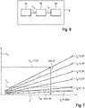
- the converter voltage V dd of the converter 54 is then determined with the intended intermediate voltage and the coupling factor k. Since the intermediate voltage is in a voltage range between the reset voltage V rst and the minimum gate-source threshold voltage V gs-thres,min , the result is as in FIG 8 Also shown is a suitable voltage range 62 for the converter voltage V dd , from which this is then selected, e.g. simply the mean value of the voltage range 62.
- the setting of the converter voltage V dd described here thus includes the in 9 shown four steps S101 - S104:
- a first step S101 a final current I tx and a final charging voltage V cc are determined.
- the coupling factor k is determined on the basis of the final current I st and the final charge voltage V cc .
- the converter voltage V dd required for this purpose is determined using the coupling factor k and the intended intermediate voltage, which converter voltage is finally set in a fourth step S104.
- the relationship used to determine the coupling factor k and the converter voltage V dd is, for example, as in FIGS 7 and 8th each shown as a parameterized bundle of functions.
- the charging voltage V cc is stored as a function of the coupling factor k and parameterized with the current I tx , resulting in a corresponding function bundle.
- the converter voltage V dd for example, as in 8 shown, the charging voltage V cc is stored as a function of the converter voltage V dd and parameterized with the coupling factor k, resulting in a corresponding function bundle.
- the final charging voltage V cc is 7.6 V
- the associated final current I tx is 0.5 A.
- the reset voltage V rst is 2 V and the minimum gate-source threshold voltage V gs-thres,min is 1 V, then for the intended intermediate voltage a voltage range between 1 V and 2 V.
- the converter voltage V dd is then set to 0.2 V, for example, so that the corresponding intermediate voltage results in the device 2 and the device 2 switches to the off state AZ.
- the gate-source threshold voltage V gs-thres must be lower than the reset voltage V rst at least in some areas.
- a suitable transistor then has a minimum gate-source threshold voltage V gs-thres,min of less than 2 V, for example 1.4 V or 0.7 V.
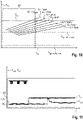
- the reset voltage V rst defines an upper limit for the converter voltage V dd for all distances A (distance A is mentioned here for the sake of simplicity, but the explanations apply generally to the coupling constant k). With the mentioned reset voltage V rst of 2 V, the upper limit for the converter voltage V dd is 0.69 V, for example. If this cannot be maintained, automatic switch-off may not be possible for some distances A. this is in 10 illustrated. For example, distance A is between 1 mm and 10 mm (in 10 the charging voltage V cc is shown as a function of the converter voltage V dd for different distances A from 1 mm to 7 mm in 1 mm increments).
- the charging voltage V cc In order to enable automatic turn-off for all distances A, the charging voltage V cc must be above the gate-source threshold voltage V gs-thres at each distance A. For those distances A for which this condition is not met, automatic switching off is not possible. From this it is clear that a transistor with as low as possible a minimum gate-source threshold voltage V gs-thres,min enables automatic turn-off for a significantly larger range of distances A. In the above example with a transistor with a minimum gate-source threshold voltage V gs-thres,min of 0.685 V, the voltage range is 64, which is available for the converter voltage V dd to provide a suitable intermediate voltage for automatic switch-off for all distances A to generate only 0.005 V.
- a lower converter voltage V dd may then be sufficient no longer off for automatic shutdown is at a distance A of 5 mm or more.
- the voltage range 66 available for the converter voltage V dd is for all distances A a suitable intermediate voltage for automatic turn-off to generate, approx. 0.2 V. This means that automatic switching off in the entire range from 1 mm to 10 mm is possible without any problems.
- the 11 and 12 each show an oscilloscope measurement in an example application.
- the charging voltage V cc and the voltage V out which is output by the energy management module 14 to the consumers 18, are shown as a function of the time t.
- the distance A between the transmitting coil 44 and the receiving coil 46 is 4 mm here.
- the device 2 first changes to the charge state LZ and is charged. To switch off automatically, proceed as in 11 As shown, the conversion voltage V dd of the converter 54 is set to 0.6V.
- the charging voltage V cc in the device 2 is thus set to an intermediate voltage of 1.5V.
- the device 2 first changes to the discharge state EZ and a few seconds later begins to consume energy, for which purpose the energy management module 14 provides the consumers 18 with a voltage V out of 1.3 V, for example.
- the device 2 then switches to the off state AZ, which then changes to 12 is active. After a few seconds (e.g. ⁇ 6 s), the converter voltage V dd is then set to 0 V in order to switch off the converter 54, so that then, as in FIG 12 shown the charging voltage V cc is 0V.
- the charger 4 can now be switched off altogether and separated from the device 2, the device 2 then remaining in the off state AZ without changing back to the discharge state EZ, although the charging voltage V cc is then 0 V.
- the device 2 and the charging device 4 each have a 58, 60 communication unit for exchanging data.
- the communication unit 60 of the charging device 4 forms a communication system for data exchange with the communication unit 58 of the device 2 .
- the communication system is used to transmit data relating to the charging voltage V cc from the device 2 the charger 4 to transmit.
- the communication system can be bidirectional or only monodirectional from the device 2 to the charging device 4.
- the communication system is wireless here and uses a corresponding communication protocol, for example magnetic induction.
- the data are modulated by device 2 for transmission.
- the charger 4 receives the data and demodulates them.
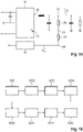
- the charging device 4 has a demodulator circuit 68, for example as in 13 shown. With the demodulator circuit 68 shown there, the current I tx in the transmission module 6 is also determined, more precisely the current I tx through the transmission coil 44, which is integrated into the demodulator circuit 68 for this purpose.
- the demodulator circuit 68 has a capacitor 70 at which the current I tx results as the ratio of a maximum object detection voltage V OD of the demodulator circuit 68 and its impedance at the transmission frequency f of the transmission coil 44 .
- the converter 54 outputs a voltage between the reset voltage Vrst and the minimum gate-source threshold voltage V gs-thres,min in the case of a contact-based automatic switch-off as the converter voltage V dd in order to switch off the device 2 .
- this voltage range for the converter voltage V dd is not necessarily applicable to wireless automatic switch-off, since in this case a lower converter voltage V dd is required for switch-off.
- the converter voltage V dd of the converter 54 is an input voltage for the oscillator 56, which amplifies the converter voltage V dd , so that a correspondingly larger charging voltage V cc ultimately results in the device 2, especially if the receiving coil 46 has more turns than the transmitter coil 44 has.
- the converter voltage V dd is therefore significantly lower in the case of wireless automatic switch-off than in the case of contact-bound automatic switch-off and is, for example, in the millivolt range.
- Converter 54 is typically unable to generate a converter voltage V dd below a feedback reference voltage V fb internal to converter 54, which is regularly at least is 0.6V.
- the charging device 4 shown here therefore has a voltage reference circuit 72 in addition to the converter 54 in order to generate a converter voltage V dd below the feedback reference voltage V fb of the converter 54 overall.
- An embodiment of such a voltage reference circuit 72 is in 14 and has a reference voltage V ref external to the converter 54 which is connected to a feedback terminal 74 of the converter 54 .
- the external reference voltage V ref is greater than the internal feedback reference voltage V fb .
- the two resistors 76, 78 form a voltage divider, with two end points 80 to which an output 82 of the converter 54 on the one hand and the external reference voltage V ref on the other hand are connected, and with a middle point 84 between the two resistors 76, 78 to which the feedback port 74 is connected.
- the charger 4 also has a control unit 86 to which the communication unit 58 and the converter 54 are connected.
- the converter 54 is adjusted by means of the control unit 86, namely based on the data which were received by means of the communication unit 58.
- the charging device 4 also has an emergency energy store 88 in order to set the intermediate voltage and to generate the switch-off signal for this purpose if the energy supply to the charging device 4 is interrupted.
- control unit 86 is designed to carry out one or more of the steps of the method described here.
- the device 2 also has a control unit 90 which, in one embodiment, is designed to carry out one or more of the steps of the method described here.
- the switch-off circuit 22 in combination with the communication system implements a method in which, initiated by the charger 4, the device 2 is automatically switched off wirelessly, specifically at the end of charging the energy store 16 of the device 2 and generally when the energy transmission is interrupted from the charger 4 to the device 2.
- the method has, for example, one or more of the 15 steps shown, preferably in the order listed.
- a first step S201 the device sends 2 data to the charger 4, for example, on a recurring basis.
- the data is analyzed, for example by the control unit 86. If the data are modulated, they are previously demodulated in the second step S202, for example using the demodulator circuit 68 described.
- a third step S203 the converter 54 is adjusted based on the data, for example from the control unit 86.
- the control unit 86 adjusts the converter 54 with a DAC signal or a PWM signal, for example.
- the converter 54 then outputs a converter voltage V dd to the oscillator 56 and thereby controls it.
- the oscillator 56 outputs a current I tx with which the transmission coil 44 is then operated.
- the current I tx is thus set indirectly by the converter 54 in the fourth step S204.
- the transmitting coil 44 generates a magnetic field M depending on the current I tx .
- a sixth step S206 the magnetic field M is received by the receiving coil 46, which generates a charging voltage V cc in the device 2 depending on it, so that the charger 4 in the device 2 a charging voltage V cc induced.
- the device 2 is then switched off if the charging voltage V cc is in the voltage range between the reset voltage V rst and the minimum gate-source threshold voltage V gs-thres,min , ie if the charging voltage V cc is an intermediate voltage such as is described. If an intermediate voltage is present, the device 2 changes to the off state AZ in the seventh step S207 and is then switched off.
- the device 2 optionally only changes to the off state AZ if, as described, a time t has also elapsed, which is longer than a switching connection active time t sca .
- the automatic switch-off takes place depending on the data that device 2 sends to charger 4 .
- Converter 54 off preferably a certain time t, for example 10 s, after the device 2 has changed to the off state AZ.
- the data then contain at least the final charging voltage V cc , which is determined in connection with the final current I tx and is also used in combination with this, in particular by the control unit 88, to determine a converter voltage V dd and to set the converter.
- events other than the end of charging are also suitable for initiating the automatic switch-off, for example when a temperature of the energy store 16 exceeds a limit temperature (overheating), when the voltage or current at the energy store 16 exceeds a corresponding limit value (overvoltage/overcurrent), generally in the event of an error in the energy store 16 (error), or similar events.
- the controller 86 then infers one or more of these events when the controller 86 analyzes the data, and then controls the converter 54 accordingly to initiate the automatic power off.
Landscapes
- Engineering & Computer Science (AREA)
- Power Engineering (AREA)
- Computer Networks & Wireless Communication (AREA)
- Health & Medical Sciences (AREA)
- General Health & Medical Sciences (AREA)
- Otolaryngology (AREA)
- Neurosurgery (AREA)
- Physics & Mathematics (AREA)
- Acoustics & Sound (AREA)
- Signal Processing (AREA)
- Charge And Discharge Circuits For Batteries Or The Like (AREA)
Abstract
Description
- Die Erfindung betrifft ein Verfahren, ein Gerät und ein Ladegerät.
- Unter "Gerät" wird vorliegend ein mobiles Gerät verstanden, das Gerät ist somit allgemein transportabel und verfügt über einen eigenen Energiespeicher zur Energieversorgung. Das Gerät ist regelmäßig einem einzelnen Nutzer zugeordnet und gegebenenfalls sogar individuell auf diesen abgestimmt. Der Energiespeicher ist regelmäßig eine Sekundärzelle (z.B. Lithium-Akku), welche durch Verbinden des mobilen Geräts mit einem Ladegerät aufladbar ist. Hierzu wird das Gerät mit dem Ladegerät kontaktgebunden oder drahtlos verbunden, um Energie vom Ladegerät an das Gerät zu übertragen und mit dieser Energie dann das Gerät, genauer dessen Energiespeicher, zu laden.
- Ein spezielles Beispiel für ein Gerät ist ein Hörgerät, welches zur Versorgung eines Nutzers dient, welcher/welche ein Hördefizit aufweist. Hierzu weist das Hörgerät ein Mikrofon auf, welches Schall aus der Umgebung aufnimmt und ein elektrisches Eingangssignal erzeugt. Dieses wird zur Modifikation einer Signalverarbeitung des Hörgeräts zugeführt. Die Modifikation erfolgt insbesondere anhand eines individuellen Audiogramms des Nutzers, sodass ein individuelles Hördefizit des Nutzers ausgeglichen wird. Die Signalverarbeitung gibt als Ergebnis ein elektrisches Ausgangssignal aus, welches dann über einen Hörer des Hörgeräts wieder in Schall umgewandelt wird und an den Nutzer ausgegeben wird. Anstelle des Mikrofons und des Hörers sind je nach Hörgerätetyp auch andere Eingangs- und/oder Ausgangswandler möglich. Das Hörgerät ist binaural oder monaural ausgebildet, d.h. zur Verwendung auf beiden Seiten beziehungsweise lediglich einer Seite des Kopfes des Nutzers.
- Andere Beispiele für Geräte sind Kopfhörer, Headsets, Wearables, Smartphones und ähnliche Geräte.
- Während des Ladens ist das Gerät in einem Ladezustand. Nach dem Laden und obwohl das Gerät noch mit dem Ladegerät verbunden ist, wird das Gerät typischerweise eingeschaltet und wechselt in einen Entladezustand oder das Ladegerät überträgt weiterhin Energie, um ein Umschalten in den Entladezustand zu verhindern. In beiden Fällen wird nachteilig Energie verbraucht.
- Vor diesem Hintergrund ist es eine Aufgabe der Erfindung, den Energieverbrauch nach dem Laden zu reduzieren. Hierzu sollen ein geeignetes Verfahren, ein Gerät sowie ein Ladegerät angegeben werden.
- Die Aufgabe wird erfindungsgemäß gelöst durch ein Verfahren mit den Merkmalen gemäß Anspruch 1, ein Gerät mit den Merkmalen gemäß Anspruch 13 und ein Ladegerät mit den Merkmalen gemäß Anspruch 15. Vorteilhafte Ausgestaltungen, Weiterbildungen und Varianten sind Gegenstand der Unteransprüche. Die Ausführungen im Zusammenhang mit dem Verfahren gelten sinngemäß auch für das Gerät und das Ladegerät sowie umgekehrt. Sofern nachfolgend Schritte des Verfahrens beschrieben sind, ergeben sich vorteilhafte Ausgestaltungen für das Gerät und das Ladegerät jeweils dadurch, dass diese ausgebildet einen oder mehrere der Schritte durchzuführen, insbesondere mittels einer jeweiligen Steuereinheit in dem Gerät beziehungsweise Ladegerät.
- Bei dem Verfahren ist ein Gerät mit einem Ladegerät verbunden und in einem Ladezustand erfolgt ein drahtloses Laden, indem mit einem Sendemodul des Ladegeräts an ein Empfangsmodul des Geräts drahtlos Energie übertragen wird. Beim Laden ist das Gerät ausgeschaltet und befindet sich in dem Ladezustand. Das Gerät weist einen Ladeanschluss auf, an welchem zum Laden eine Ladespannung Vcc anliegt, welche mit dem Ladegerät einstellbar ist. Weiter weist das Gerät einen Schaltanschluss auf, zum Ein- und Ausschalten des Geräts. Der Ladeanschluss und der Schaltanschluss sind vorzugsweise Anschlüsse eines Energiemanagementmoduls (auch als PMIC bezeichnet) des Geräts. Das Energiemanagementmodul nimmt die Ladespannung entgegen und lädt damit einen Energiespeicher, z.B. Lithium-Akku, des Geräts.
- Das Gerät weist auch einen Entladezustand auf, in welchem Energie verbraucht wird, nämlich von einem oder mehreren Verbrauchern des Geräts. Im Entladezustand steuert das Energiemanagementmodul die Bereitstellung von Energie für die Verbraucher aus dem Energiespeicher des Geräts. Im Ladezustand empfängt das Gerät somit Energie vom Ladegerät, im Entladezustand verbraucht das Gerät Energie. Im Ladezustand ist das Gerät notwendigerweise mit dem Ladegerät verbunden, im Entladezustand ist das Gerät entweder vom Ladegerät getrennt oder mit diesem verbunden. Unter "das Gerät ist eingeschaltet" wird verstanden, dass die Verbraucher insbesondere mittels des Energiemanagementmoduls mit Energie versorgt werden, unter "das Gerät ist ausgeschaltet" wird dann verstanden, dass die Verbraucher nicht mit Energie versorgt werden, gleichwohl kann das Energiemanagementmodul weiterhin Energie verbrauchen. Im Entladezustand ist das Gerät prinzipbedingt auch eingeschaltet. Sofern nachfolgend beschrieben wird, dass das Gerät "ausgeschaltet wird", wird darunter verstanden, dass das Gerät erstens, falls es eingeschaltet ist, "ausgeschaltet wird", und zweitens, falls das Gerät bereits ausgeschaltet ist, "ausgeschaltet bleibt".
- Das Gerät weist außerdem einen Schalter auf, welcher mit dem Schaltanschluss verbunden ist und welcher mit der Ladespannung schaltbar ist, indem die Ladespannung auf eine Zwischenspannung eingestellt wird. Der Schalter ist insbesondere ein Teil einer Ausschalt-Schaltung des Geräts. Das Ladegerät stellt die Ladespannung auf die Zwischenspannung ein, sodass der Schalter geschaltet wird und das Gerät in einen Aus-Zustand wechselt, in welchem das Gerät ausgeschaltet ist. Darunter wird insbesondere verstanden: Das Gerät wird (d.h. wird oder bleibt) mittels des Ladegeräts ausgeschaltet, indem das Ladegerät die Ladespannung auf die Zwischenspannung einstellt, sodass der Schalter geschaltet wird und das Gerät in einen Aus-Zustand wechselt. Dies, d.h. das Einstellen der Zwischenspannung und der darauffolgende Wechsel in den Aus-Zustand, erfolgt insbesondere beim Beenden oder Unterbrechen des Ladens, kann aber grundsätzlich auch allgemein in einem Fehlerfall erfolgen, z.B. bei Überhitzung oder Überspannung/Überstrom des Energiespeichers. Damit wird mit dem Ladegerät ein automatisches Ausschalten realisiert, sobald keine Energie mehr an das Gerät übertragen wird. Das Ladegerät initiiert damit einen Wechsel des Geräts in den Aus-Zustand, in welchem das Gerät dann - anders als im Entladezustand - keine Energie mehr verbraucht. Hierbei nutzt das Ladegerät die Möglichkeit, die Ladespannung variabel einzustellen. Durch das automatische Ausschalten wird somit nach dem Laden vorteilhaft Energie gespart, da das Gerät ausgeschaltet wird und somit gerade nicht in den Entladezustand wechselt.
- Das Gerät ist ein mobiles Gerät und somit allgemein transportabel. Das Gerät ist regelmäßig einem einzelnen Nutzer zugeordnet und gegebenenfalls sogar individuell auf diesen abgestimmt. Der Energiespeicher ist regelmäßig eine Sekundärzelle (z.B. Lithium-Akku), welche durch Verbinden des Geräts mit dem Ladegerät aufladbar ist.
- Bevorzugterweise ist das Gerät ein Hörgerät, welches zur Versorgung eines Nutzers dient, welcher/welche ein Hördefizit aufweist. Hierzu weist das Hörgerät ein Mikrofon auf, welches Schall aus der Umgebung aufnimmt und ein elektrisches Eingangssignal erzeugt. Dieses wird zur Modifikation einer Signalverarbeitung des Hörgeräts zugeführt. Die Modifikation erfolgt insbesondere anhand eines individuellen Audiogramms des Nutzers, sodass ein individuelles Hördefizit des Nutzers ausgeglichen wird. Die Signalverarbeitung gibt als Ergebnis ein elektrisches Ausgangssignal aus, welches dann über einen Hörer des Hörgeräts wieder in Schall umgewandelt wird und an den Nutzer ausgegeben wird. Anstelle des Mikrofons und des Hörers sind je nach Hörgerätetyp auch andere Eingangs- und/oder Ausgangswandler möglich. Das Hörgerät ist binaural oder monaural ausgebildet, d.h. zur Verwendung auf beiden Seiten beziehungsweise lediglich einer Seite des Kopfes des Nutzers. Eingangswandler (z.B. Mikrofon), Ausgangswandler (z.B. Hörer), Signalverarbeitung sind Verbraucher des Geräts.
- Alternativ ist das Gerät ein Kopfhörer, Headset, Wearable, Smartphone oder dergleichen.
- Zum Laden wird das Gerät mit dem Ladegerät verbunden und hierzu geeigneterweise in dieses eingelegt, eingesetzt oder auf dieses aufgelegt. Beispielsweise ist das Ladegerät als Ladeschale ausgebildet, mit einer Vertiefung, in welche das Gerät einlegbar ist. Optional weist das Ladegerät einen Deckel auf, um das Ladegerät zu verschließen und dabei die Vertiefung zu verdecken, sodass das Gerät insgesamt im Inneren des Ladegeräts eingeschlossen ist. Die Vertiefung ist zweckmäßigerweise derart geformt, dass das Gerät darin in einer möglichst definierten Anordnung relativ zur Ladeschale gehalten ist.
- Je nachdem, welche Ladung der Energiespeicher aufweist, d.h. wie voll der Energiespeicher geladen ist, stellt dieser für einen oder mehrere Verbraucher eine Spannung Vbat bereit, welche gegebenenfalls zuvor noch mit einer Transformationseinheit transformiert wird, z.B. im Energiemanagementmodul, sodass dieses dann eine Spannung Vout an die Verbraucher ausgibt. Je größer die Ladung, desto größer ist diese Spannung typischerweise. Das Gerät wird vom Ladegerät mit einer Ladespannung Vcc (d.h. "charging input voltage") geladen, wobei die Ladespannung diejenige Spannung ist, welche im Gerät zum Laden des Energiespeichers vorliegt. Der Energiespeicher wird dann solange geladen, bis die gewünschte Ladung oder Spannung erreicht ist. Hierzu wird geeigneterweise eine Ladeschwellenspannung Vchg,thres (d.h. "charging threshold voltage") vorgegeben, welche mit der Ladespannung verglichen wird, um festzulegen, wann geladen wird und wann nicht. Vorzugsweise wird das Laden dann beendet, wenn die Ladespannung die Ladeschwellenspannung unterschreitet. Die Ladeschwellenspannung ist beispielsweise eine fest vorgegebene Spannung.
- Um das Gerät auszuschalten (d.h. das Gerät wird oder bleibt ausgeschaltet), nachdem dieses vollständig aufgeladen wurde, ist ein automatisches Ausschalten (d.h. "automatic switch-off") vorteilhaft. Das automatische Ausschalten wird dabei vorliegend zwar vom Gerät selbst durchgeführt, von diesem jedoch nicht selbst initiiert, sondern vom Ladegerät, sodass das automatische Ausschalten genauer gesagt ein "extern veranlasstes, automatisches Ausschalten" ist. Das Ladegerät bestimmt, wann das Gerät ausgeschaltet werden soll und sendet dann ein Ausschaltsignal an das Gerät, sodass dieses ausgeschaltet wird. Vorliegend führt das Ausschaltsignal dazu, dass im Gerät die Zwischenspannung vorliegt. Ohne ein automatisches Ausschalten würde fortlaufend auch nach dem Laden das Gerät eingeschaltet und Energie verbraucht, insbesondere wenigstens vom Energiemanagementmodul zu dessen Betrieb. Selbst wenn der hierbei verwendete Strom typischerweise lediglich gering ist, so wird dennoch vom Gerät Energie verbraucht. Diese Energie wird weiterhin gegebenenfalls auch dem Ladegerät entnommen, während dieses nach dem eigentlichen Laden noch mit dem Gerät verbunden ist. Speziell bei einem portablen Ladegerät mit einem eigenen Energiespeicher würde dieser Energiespeicher fortlaufend vom Gerät entladen, insbesondere, um das Gerät daran zu hindern, sich einzuschalten und in den Entladezustand zu wechseln. Außerdem existieren regelmäßig Spezifikationen, welche sicherstellen sollen, dass ein Gerät mit anderen Geräten kompatibel ist. Eine solche Spezifikation ist beispielsweise "Made for iPhone/iPod/iPad", kurz MFi. Beispielsweise fordert eine Spezifikation, dass eine BLE-Funktion (BLE = Bluetooth Low Energy) des Geräts ausgeschaltet ist und das Gerät somit nicht in einem Kopplungsmodus oder einem Anbietemodus betrieben wird, solange das Gerät mit dem Ladegerät verbunden ist und solange keine explizite Nutzereingabe zum Einschalten der BLE-Funktion erfolgt. Hinsichtlich des Kopplungsmodus fordert die Spezifikation demnach, dass das Gerät, während dieses mit dem Ladegerät verbunden ist, nicht mit einem anderen Gerät koppelbar sein soll. Hinsichtlich des Anbietemodus fordert die Spezifikation dann, dass das Gerät, während dieses mit dem Ladegerät verbunden ist, kein Bereitschaftssignal (zum Anzeigen der eigenen Bereitschaft zur Kopplung) an andere Geräte aussenden soll.
- Einige Szenarien führen jedoch möglicherweise dazu, dass das Gerät nach dem Laden, aber noch während dieses Gerät mit dem Ladegerät verbunden ist, eingeschaltet wird oder ist und somit im Entladezustand betrieben wird, in welchem dann entgegen der Spezifikation auch die BLE-Funktion eingeschaltet ist. Ein erstes solches Szenario ist ein Stromausfall, bei welchem eine Energieversorgung des Ladegeräts unterbrochen wird. Ein zweites Szenario ist ein Entfernen eines Stromkabels des Ladegeräts, wobei das Kabel das Ladegerät mit einem Stromnetz verbindet, z.B. über eine Haushaltssteckdose. Das zweite Szenario ist im Grunde ähnlich dem ersten Szenario. Ein drittes Szenario ist, dass ein Energiespeicher eines portablen Ladegeräts vollständig entladen ist, sodass das Ladegerät keine Energie mehr zum Laden für das Gerät zur Verfügung stellen kann. In all diesen Szenarien wird keine Energie mehr an das Gerät übertragen und daher das Gerät typischerweise in den Entladezustand versetzt. Als Folge davon ist das Gerät eingeschaltet, anstatt ausgeschaltet. Entsprechend sind dann auch energieverbrauchende Funktionen, wie z.B. die BLE-Funktion eingeschaltet.
- Allgemein, speziell jedoch wegen der Spezifikation wie beschrieben, ist es somit wünschenswert, nach dem Laden das Gerät auszuschalten, solange dieses noch mit dem Ladegerät verbunden ist. Das Gerät soll beim Beenden des Ladezustands möglichst nicht in den Entladezustand versetzt und eingeschaltet werden, sondern das Gerät soll ausgeschaltet werden.
- Zur Erfüllung der Spezifikation ist es vorteilhaft, den Ladeanschluss des Energiemanagementmoduls des Geräts zu verwenden, um ein automatisches Ausschalten zu realisieren und dadurch das Gerät nach dem Laden auszuschalten. Der Ladeanschluss ist ein elektrischer Kontakt, z.B. ein Kontaktpin, über welchen das Gerät mit dem Ladegerät zum Laden verbunden ist und somit beim kontaktgebundenen Laden auch galvanisch gekoppelt ist. Am Ladeanschluss liegt die Ladespannung an, der Ladeanschluss ist somit allgemein ein Leistungskontakt. Auch der Schaltanschluss ist z.B. als Kontaktpin ausgebildet. Der Schaltanschluss ist insbesondere mit einem Pull-Up-Widerstand hochgezogen. Zwischen dem Schaltanschluss und Masse ist zum manuellen Ausschalten des Geräts zweckmäßigerweise ein Schalter angeschlossen, welcher manuell betätigbar ist. Zum automatischen Ausschalten mittels des Ladegeräts weist das Gerät unabhängig davon dann die bereits genannte Ausschalt-Schaltung mit Schalter auf, welche den Ladeanschluss und den Schaltanschluss nutzt. Der Schalter ist vorzugsweise ein Transistor, mit Gate, Source und Drain, d.h. mit entsprechenden Anschlüssen. Die Begriffe Gate, Drain und Source werden hier und nachfolgend zur Bezeichnung der drei Anschlüsse des Transistors verwendet. Die Ausführungen gelten jedoch ganz allgemein für jeden Schalter mit drei Anschlüssen, welche Gate, Source und Drain eines Transistors funktional gleichwertig sind. Das Gate des Transistors ist mit dem Ladeanschluss und mit einem Widerstand der Ausschalt-Schaltung auf die Ladespannung hochgezogen. Der Widerstand verbindet das Gate mit der Source und mit Masse. Der Drain und die Source des Transistors sind mit dem Schaltanschluss beziehungsweise mit Masse verbunden.
- Ganz allgemein und speziell mittels der Ausschalt-Schaltung wie oben beschrieben, ist mit dem automatischen Ausschalten vorteilhaft ein zusätzlicher Betriebszustand für das Gerät realisiert, nämlich der Aus-Zustand, in welchem das Gerät zwar an das Ladegerät angeschlossen ist, dabei jedoch ausgeschaltet ist und damit weder selbst Energie verbraucht, noch Energie vom Ladegerät empfängt. Demgegenüber ist das Gerät im Ladezustand ausgeschaltet, empfängt dabei aber noch Energie (insbesondere zum Betrieb des Energiemanagementmoduls), und im Entladezustand eingeschaltet und verbraucht Energie. Zum Wechseln zwischen dem Ladezustand und dem Entladezustand (in beiden Richtungen) weist das Gerät zusätzlich insbesondere noch einen Wartezustand (d.h. "idle state") auf, sodass insgesamt vier Betriebszustände möglich sind, welche sich insbesondere auch gegenseitig ausschließen.
- Das Gerät wechselt vorzugsweise dann vom Entladezustand, vom Aus-Zustand oder vom Wartezustand in den Ladezustand, wenn die Ladespannung wenigstens der Ladeschwellenspannung entspricht. Solange die Ladespannung wenigstens der Ladeschwellenspannung entspricht bleibt der Ladezustand aktiv. Das Gerät wechselt vom Ladezustand in den Wartezustand, wenn die Ladespannung geringer ist als die Ladeschwellenspannung. Das Gerät wechselt vom Wartezustand in den Entladezustand, wenn die Ladespannung geringer ist als eine Reset-Spannung Vrst und zusätzlich insbesondere, wenn auch eine Zeit verstrichen ist, welche länger ist als eine Entladezeit tdisc. Die Reset-Spannung ist beispielsweise eine fest vorgegebene Spannung und insbesondere ein Parameter des Energiemanagementmoduls. Die Reset-Spannung dient insbesondere dazu, den Betrieb des Energiemanagementmoduls zu stoppen und dieses auf einen vordefinierten Standardzustand zu initialisieren, indem am Energiemanagementmodul eine Spannung angelegt wird, welche wenigstens der Reset-Spannung entspricht. Diese Initialisierung ermöglicht dann nachfolgend einen ordnungsgemäßen Betrieb. Die Reset-Spannung wird vorliegend insbesondere auch genutzt, um festzulegen, wann vom Wartezustand in den Entladezustand gewechselt wird. Die Entladezeit ist beispielsweise eine fest vorgegebene Zeit von wenigen Sekunden. Umgekehrt wechselt das Gerät vom Entladezustand in den Wartezustand, wenn die Ladespannung geringer ist als die Ladeschwellenspannung und größer als die Reset-Spannung, und vom Wartezustand in den Ladezustand, wenn die Ladespannung wenigstens der Ladeschwellenspannung entspricht. Solange die Ladespannung geringer ist als die Ladeschwellenspannung, bleibt der Wartezustand aktiv.
- Das automatische Ausschalten, d.h. ein Wechsel in den Aus-Zustand, ist nun dadurch realisiert, dass die Ladespannung am Ladeanschluss auf eine Zwischenspannung eingestellt wird, welche eine Gate-Source-Schwellenspannung Vgs-thres des Transistors ist und zweckmäßigerweise zwischen der Reset-Spannung und einer Gate-Source-Mindestschwellenspannung, d.h. einem Mindestwert für die Gate-Source-Schwellenspannung, liegt. Die Gate-Source-Schwellenspannung ist diejenige Spannung, welche zum Schalten (insbesondere Einschalten) des Transistors erforderlich ist und liegt insbesondere in einem Bereich zwischen der Gate-Source-Mindestschwellenspannung (diejenige Spannung, welche wenigstens zum Schalten des Transistors nötig ist) und einer Gate-Source-Maximalschwellenspannung (diejenige Spannung, welche höchstens zum Schalten des Transistors möglich ist). Die Reset-Spannung ist insbesondere größer als die tatsächlich genutzte Gate-Source-Schwellenspannung, die Gate-Source-Maximalschwellenspannung kann jedoch größer sein als die Reset-Spannung. Zweckmäßigerweise weist der Transistor eine möglichst große Differenz zwischen der Gate-Source-Mindestschwellenspannung und der Gate-Source-Maximalschwellenspannung auf. Die Gate-Source-Maximalschwellenspannung beträgt beispielsweise 20 V.
- Durch die Gate-Source-Mindestschwellenspannung einerseits und die Reset-Spannung andererseits ist nun für die Zwischenspannung ein Spannungsbereich aufgespannt, welcher zum Wechseln in den Aus-Zustand genutzt wird. Wenn die Ladespannung geringer ist als die Reset-Spannung, wechselt das Gerät in den Entladezustand. Grundsätzlich ist zunächst der Entladezustand solange aktiv, wie die Ladespannung geringer ist als die Gate-Source-Mindestschwellenspannung. Das Gerät wechselt dann in den Aus-Zustand, wenn die Ladespannung geringer ist als die Reset-Spannung und größer als die Ladeschwellenspannung, und zusätzlich insbesondere, wenn auch eine Zeit (während welcher die Zwischenspannung gehalten wird) verstrichen ist, welche länger ist als eine Schaltanschluss-Aktiv-Zeit tsca. Entsprechend wird dann, sobald am Gate des Transistors die Zwischenspannung erreicht ist, der Transistor geschaltet und der Schaltanschluss auf Masse gezogen. Das Gerät wechselt kurzzeitig in den Entladezustand und von dort aus in den Aus-Zustand, insbesondere nach der Schaltanschluss-Aktiv-Zeit. Die Schaltanschluss-Aktiv-Zeit ist beispielsweise eine fest vorgegebene Zeit von z.B. wenigen Sekunden. Ein Wechsel in den Aus-Zustand ist vorzugsweise ausschließlich ausgehend vom Entladezustand möglich.
- Ein Einschalten des Geräts und speziell ein Wechsel vom Aus-Zustand in den Entladezustand, ist zunächst über den Ladezustand möglich. In einer geeigneten Ausgestaltung wechselt das Gerät vom Aus-Zustand in den Ladezustand, wenn die Ladespannung wenigstens der Ladeschwellenspannung entspricht. Alternativ oder zusätzlich ist ein Wechsel aus dem Aus-Zustand durch ein manuelles Einschalten des Geräts durch den Nutzers möglich. Hierfür weist das Gerät insbesondere einen Schalter auf, z.B. einen Knopf, Taster, Schiebeschalter oder Vergleichbares.
- Die beschriebene Lösung zum automatischen Ausschalten des Geräts ist bei einem kontaktgebundenen Laden ohne weiteres möglich, da hierbei eine galvanische Verbindung besteht, über welche die Zwischenspannung auf einfache Weise einstellbar ist. Da die Ladespannung unmittelbar vom Ladegerät bereitgestellt wird, ist die Zwischenspannung entsprechend einfach einstellbar. Bei einem Ladegerät zum drahtlosen Laden ist dies jedoch nicht ohne weiteres möglich, da die Ladespannung nicht direkt vom Ladegerät bereitgestellt wird, sondern von diesem mittels des Sendemoduls lediglich im Gerät induziert wird und somit im Ladegerät selbst nicht unbedingt vorliegt. Ohne ein automatisches Ausschalten muss das Ladegerät jedoch fortlaufend Energie an das Gerät übertragen, um ein Aktivieren des Entladezustands zu verhindern und bei einer Unterbrechung der Energiezufuhr würde das Gerät regelmäßig automatisch in den Entladezustand versetzt, gegebenenfalls mit dazwischen aktiviertem Wartezustand wie oben beschrieben. Ein Ausgangspunkt der vorliegenden Erfindung ist nun insbesondere, den Aus-Zustand wie beschrieben speziell für ein Ladegerät zum drahtlosen Laden zu realisieren, also gerade nicht kontaktgebunden, sondern drahtlos. Die bisherigen Ausführungen gelten sowohl für ein kontaktgebundenes wie auch für ein drahtloses Laden. Bei einem Ladegerät zum drahtlosen Laden erfolgt der Energietransfer vom Ladegerät zum Gerät mittels einem Sendemodul im Ladegerät und einem Empfangsmodul im Gerät.
- Beim Laden erfolgt eine Energieübertragung vorzugsweise mittels eines Magnetfelds, welches mit einer Sendespule des Sendemoduls erzeugt wird und welches mit einer Empfangsspule des Empfangsmoduls empfangen wird. Um dann bei einem drahtlosen Ladegerät die Ladespannung auf die Zwischenspannung einzustellen, wird entsprechend das Sendemodul derart angesteuert, dass im Gerät die Zwischenspannung induziert wird. Ein wichtiger Vorteil der vorliegenden Erfindung ist insbesondere, dass mit dem Ladegerät das Gerät drahtlos ausgeschaltet wird. Hierzu wird mit dem Magnetfeld des Ladegeräts die Ladespannung auf die Zwischenspannung eingestellt, sodass das Gerät in den Aus-Zustand wechselt. Damit ist ein drahtloses automatisches Ausschalten mittels eines Magnetfelds realisiert. Das ansonsten zum Laden verwendete Magnetfeld stellt somit bei entsprechender Ansteuerung zugleich das Ausschaltsignal dar, welches vom Ladegerät an das Gerät gesendet wird. Hierzu sind das Gerät und das Ladegerät entsprechend geeignet ausgebildet. Insbesondere wird im Ladegerät das Magnetfeld, welches allgemein im Gerät die Ladespannung induziert, derart geändert, dass die Zwischenspannung erzeugt wird. Der Aus-Zustand wird insbesondere dann automatisch aktiviert, wenn das Gerät vollständig geladen ist oder das Ladegerät keine Energie mehr bereitstellt (siehe die diversen Szenarien weiter oben), sodass das Gerät dann ausgeschaltet ist und keine Energie verbraucht. Das drahtlose automatische Ausschalten ist weiterhin vorteilhaft, da dadurch im Vergleich zu einem kontaktgebundenen automatischen Ausschalten eine freiere räumliche Anordnung des Geräts und des Ladegeräts relativ zueinander möglich ist, zumindest innerhalb der Grenzen, in welchen noch eine Energieübertragung zum Laden möglich ist.
- Das Ladegerät und das Gerät zum drahtlosen Laden bilden zusammen ein drahtloses Ladesystem. Das Gerät weist insbesondere zusätzlich zum Energiemanagementmodul und dem Energiespeicher noch das bereits erwähnte Empfangsmodul auf sowie einen oder mehrere Verbraucher. Die Verbraucher werden im Entladezustand mit Energie aus dem Energiespeicher betrieben, Beispiele für Verbraucher sind ein BLE-Modul, welches eine BLE-Funktion bereitstellt, eine Signalverarbeitungseinheit oder elektroakustische Verbraucher, z.B. ein Hörer oder ein Mikrofon. Das Empfangsmodul stellt die Ladespannung bereit und gibt diese an das Energiemanagementmodul aus. Das Empfangsmodul ist ausgebildet zum Empfangen von Energie vom Ladegerät, welches entsprechend zum Senden der Energie das bereits erwähnte Sendemodul aufweist. Geeigneterweise weist das Sendemodul zum Senden von Energie eine Sendespule auf und das Empfangsmodul weist analog zum Empfangen der Energie eine Empfangsspule auf. Die Sendespule wird allgemein mit einer Stromquelle des Ladegeräts betrieben. Das Empfangsmodul weist zweckmäßigerweise eine Beschaltung für die Empfangsspule auf, um die Ladespannung zu erzeugen. Die Beschaltung weist beispielsweise einen Abstimmkondensator, einen Glättungskondensator und eine Schottky-Diode auf.
- Die Ladespannung Vcc ist typischerweise von einer Vielzahl an Parametern abhängig, insbesondere vom Strom Itx zur Sendespule, der jeweiligen Induktivität der Sendespule Ltx und der Empfangsspule Lrx, einer Übertragungsfrequenz f , welche zur Übertragung der Energie mittels des Magnetfelds genutzt wird, und einem Kopplungsfaktor k. Der Kopplungsfaktor wiederum ist insbesondere abhängig vom Abstand und vom Neigungswinkel zwischen der Sendespule und der Empfangsspule, d.h. allgemein von der räumlichen Anordnung des Ladegeräts und des Geräts beim Laden. Je geringerer der Abstand und je geringer der Neigungswinkel, desto größer der Kopplungsfaktor. Für die Ladespannung gilt allgemein: Vcc ∝ 2π · f · k · √(Ltx · Lrx) · Itx. Daraus wird speziell deutlich, dass die Ladespannung, welche tatsächlich im Gerät vorliegt, von einigen Parametern (Übertragungsfrequenz, Induktivität der Sendespule, Strom zum Betrieb der Sendespule) des Ladegeräts abhängt und entsprechend von diesem manipulierbar ist.
- Die Ausschalt-Schaltung für das drahtlose automatische Ausschalten ist grundsätzlich wie für das kontaktgebundene automatische Ausschalten ausgebildet. Mit anderen Worten: die Ausschalt-Schaltung weist einen Schalter auf, vorzugsweise einen Transistor, welcher durch die Zwischenspannung, geschaltet (insbesondere eingeschaltet) wird. Der Transistor der Ausschalt-Schaltung ist bevorzugterweise ein MOSFET. Der Widerstand, welcher Gate und Source des Transistors verbindet, weist geeigneterweise einen hohen Wert auf, z.B. 100 kΩ und allgemein bevorzugterweise zwischen 10 kΩ und 1 MΩ. Das Gate ist auf die Ladespannung vom Empfangsmodul hochgezogen. Der Drain ist mit dem Schaltanschluss des Energiemanagementmoduls verbunden, die Source mit Masse. Auf diese Weise werden wie bereits beschrieben vier Betriebszustände ermöglichst, unter anderem der Aus-Zustand.
- Das Ladegerät weist zum drahtlosen Energietransfer geeigneterweise noch einen Umwandler und einen Oszillator auf. Der Oszillator erzeugt einen Strom zum Betrieb der Sendespule und ist demnach eine Stromquelle. Die Sendespule und der Oszillator bilden dann das Sendemodul. Der Oszillator ist beispielsweise ein Wechselrichter oder Leistungsverstärker und erzeugt allgemein einen Strom (d.h. Wechselstrom) zur Erzeugung des Magnetfelds mit dem Sendemodul. Der Umwandler hingegen erzeugt eine Wandlerspannung, zum Betrieb des Oszillators. Der Umwandler beeinflusst somit den Strom, mit welchem die Sendespule betrieben wird. Die Ladespannung und damit speziell auch die Zwischenspannung wird somit mittels der Wandlerspannung eingestellt. Bevorzugterweise ist der Umwandler ein Abwärtswandler (auch als Tiefsetzsteller oder "buck converter" bezeichnet), welcher ausgebildet ist, eine Eingangsspannung in eine demgegenüber reduzierte Ausgangsspannung, nämlich die Wandlerspannung umzuwandeln. Der Umwandler ist insbesondere mit einer Energiequelle für das Ladegerät verbunden oder verbindbar, z.B. mit einem Energiespeicher des Ladegeräts oder mit einem Stromnetz außerhalb des Ladegeräts.
- Für feste Werte der Induktivitäten von Sendespule und Empfangsspule und der Übertragungsfrequenz steigt die Ladespannung insbesondere jeweils linear einerseits mit steigendem Kopplungsfaktor sowie andererseits mit steigendem Strom zur Sendespule. Diese beiden Zusammenhänge, nämlich zwischen Ladespannung und Kopplungsfaktor einerseits und zwischen Ladespannung und Strom andererseits, werden vorliegend vorteilhaft genutzt, um bei bekanntem Kopplungsfaktor die Ladespannung im Gerät mittels des Stroms zur Sendespule im Ladegerät zu steuern und damit gezielt den Aus-Zustand zu aktivieren. Die Wandlerspannung des Umwandlers im Ladegerät steuert den Oszillator, welcher wiederum den Strom zur Sendespule steuert. Mit dem Umwandler und dessen Wandlerspannung ist somit zunächst der Strom zur Sendespule einstellbar und dann letztendlich auch die Ladespannung im Gerät, welche auf diese Weise auch auf die Zwischenspannung einstellbar ist. Der Aus-Zustand des Geräts wird dann extern vom Ladegerät durch eine geeignete Steuerung des Umwandlers und Einstellen von dessen Wandlerspannung aktiviert. Der Zusammenhang zwischen Wandlerspannung Vdd und Ladespannung Vcc ist wie oben beschrieben durch Vcc ∝ 2π · f · k · √(Ltx · Lrx) · Itx, wobei der Strom Itx wie beschrieben eine Funktion der Wandlerspannung Vdd ist, geeigneterweise ist der Strom proportional zur Wandlerspannung.
- Die Wandlerspannung, welche einzustellen ist, um eine bestimmte Ladespannung und insbesondere die Zwischenspannung zu erzeugen, ist - wie oben beschrieben - abhängig von dem Kopplungsfaktor zwischen dem Sendemodul und dem Empfangsmodul und kann grundsätzlich variieren. Die Induktivitäten und die Übertragungsfrequenz sind dagegen für ein gegebenes Ladesystem prinzipbedingt bekannt. Die Übertragungsfrequenz liegt vorzugsweise zwischen 3 MHz und 30 MHz und beträgt beispielsweise 13,56 MHz. In einer bevorzugten Ausgestaltung werden daher zum Erzeugen der Zwischenspannung die Wandlerspannung und somit auch der Strom eingestellt, indem zunächst der Kopplungsfaktor bestimmt wird und dann mit diesem diejenige Wandlerspannung bestimmt wird, welche benötigt wird, um die Zwischenspannung zu erzeugen. Dies erfolgt anhand des Zusammenhangs zwischen Ladespannung und Wandlerspannung, nämlich Vcc ∝ 2π · f · k · √(Ltx · Lrx) · Itx(Vdd). Zum automatischen Ausschalten wird dann die auf diese Weise bestimmte Wandlerspannung eingestellt, sodass dann im Gerät die Zwischenspannung induziert wird und das Gerät in den Aus-Zustand wechselt.
- Der Kopplungsfaktor wird geeigneterweise ebenfalls über den Zusammenhang zwischen Ladespannung und Strom/Wandlerspannung bestimmt, nun aber mit einem bekannten Wertepaar für die Ladespannung Vcc und den Strom Itx. Da die Ladespannung dem Ladegerät nicht bekannt ist, ist zur Ermittlung des Kopplungsfaktors dann eine Kommunikation zwischen dem Ladegerät und dem Gerät vorteilhaft. Am Ende des Ladens, wenn also keine Energie mehr an das Gerät übertragen wird, sendet das Gerät die zuletzt noch während des Ladens anliegende Ladespannung (genauer gesagt: deren Wert) an das Ladegerät. Diese zuletzt noch anliegende Ladespannung wird auch als "finale Ladespannung" bezeichnet. Die finale Ladespannung ist insbesondere größer als die Reset-Spannung und die Gate-Source-Schwellenspannung. Zudem speichert das Ladegerät denjenigen Strom (genauer gesagt: dessen Wert), welcher zum Zeitpunkt der finalen Ladespannung zum Betrieb der Sendespule genutzt wird, d.h. den zuletzt noch während des Ladens anliegenden Strom, welcher analog als finaler Strom bezeichnet wird. Die finale Ladespannung wird über eine Datenverbindung zwischen dem Gerät und dem Ladegerät gesendet. Hierfür weisen das Gerät und das Ladegerät jeweils eine Kommunikationseinheit auf, z.B. eine Antenne und eine geeignete Schaltung für die Antenne, zum Senden und/oder Empfangen von Daten, speziell der finalen Ladespannung. Das Ladegerät empfängt die finale Ladespannung, woraufhin dann in Kombination mit dem finalen Strom der Kopplungsfaktor bestimmt wird, insbesondere über den genannten Zusammenhang.
- Mit der beabsichtigen Zwischenspannung und dem Kopplungsfaktor wird dann die Wandlerspannung des Umwandlers bestimmt. Da die Zwischenspannung in einem Spannungsbereich zwischen der Reset-Spannung und der Gate-Source-Mindestschwellenspannung liegt, ergibt sich entsprechend auch für die Wandlerspannung dann ein geeigneter Spannungsbereich, aus welchem dann die Wandlerspannung ausgewählt wird, z.B. einfach der Mittelwert des Spannungsbereichs.
- Zusammenfassend umfasst das Einstellen der Wandlerspannung somit vorzugsweise die folgenden vier Schritte: In einem ersten Schritt werden ein finaler Strom und eine finale Ladespannung ermittelt. Darauffolgend wird in einem zweiten Schritt der Kopplungsfaktor anhand des finalen Stroms und der finalen Ladespannung bestimmt. Darauffolgend wird in einem dritten Schritt mit dem Kopplungsfaktor und der beabsichtigten Zwischenspannung die hierfür nötige Wandlerspannung bestimmt. Diese Wandlerspannung wird schließlich in einem vierten Schritt eingestellt.
- Der zur Bestimmung des Kopplungsfaktors und der Wandlerspannung jeweils verwendete Zusammenhang ist beispielsweise als Funktion oder als Tabelle in einem Speicher des Ladegeräts hinterlegt. Zweckmäßigerweise ist der Zusammenhang Vcc ∝ 2π · f · k · √(Ltx · Lrx) · Itx(Vdd) hierfür jeweils als parametriertes Funktionsbündel hinterlegt. Zur Bestimmung des Kopplungsfaktors ist die Ladespannung insbesondere als Funktion des Kopplungsfaktors hinterlegt und mit dem Strom parametriert, sodass sich ein entsprechendes Funktionsbündel ergibt. Zur Bestimmung der Wandlerspannung ist die Ladespannung insbesondere als Funktion der Wandlerspannung hinterlegt und mit dem Kopplungsfaktor parametriert, sodass sich ein entsprechendes Funktionsbündel ergibt.
- Nachfolgend werden zur Illustration typische Zahlenbeispiele beschrieben, welche jedoch nicht beschränkend zu verstehen ist, aber jedenfalls geeignete Größenordnungen angeben.
- Die finale Ladespannung beträgt beispielsweise 7,6 V, der zugehörige finale Strom beträgt beispielsweise 0,5 A. Anhand dieser Werte und in Kombination mit den Induktivitäten und der Übertragungsfrequenz wird der Kopplungsfaktor beispielshaft als k = 0,07 bestimmt. Die Reset-Spannung beträgt beispielsweise 2 V und die Gate-Source-Mindestschwellspannung 1 V, dann ergibt sich für die beabsichtigte Zwischenspannung ein Spannungsbereich zwischen 1 V und 2 V. Für diese Zwischenspannung wird dann mit dem Kopplungsfaktor k = 0,07 beispielhaft eine Wandlerspannung im Bereich von 0,125 V und 0,275 V bestimmt. Die Wandlerspannung wird dann beispielsweise auf 0,2 V eingestellt, sodass sich im Gerät die entsprechende Zwischenspannung ergibt und das Gerät in den Aus-Zustand wechselt, drahtlos initiiert durch das Ladegerät.
- Ein jeweiliger Transistor ist insbesondere nur dann geeignet, wenn dessen Gate-Source-Schwellenspannung zumindest bereichsweise kleiner ist als die Reset-Spannung, andere Transistoren sind dagegen ungeeignet für die Ausschalt-Schaltung. Für die oben beispielhaft genannte Reset-Spannung von 2 V ergibt sich dann, dass ein geeigneter Transistor eine Gate-Source-Mindestschwellenspannung von weniger als 2 V aufweist, z.B. 1,4 V oder 0,7 V.
- Die Reset-Spannung definiert für sämtliche Abstände insbesondere eine Obergrenze für die Wandlerspannung, denn diese darf denjenigen Wert nicht überschreiten, welcher im Gerät zur Überschreitung der Reset-Spannung führt (der Einfachheit halber wird hier vom Abstand gesprochen, die Ausführungen gelten jedoch allgemein für die Kopplungskonstante). Bei der beispielhaft genannten Reset-Spannung von 2 V beträgt die Obergrenze für die Wandlerspannung beispielsweise 0,69 V. Sofern dies nicht eingehalten werden kann, ist ein automatisches Ausschalten für einige Abstände unter Umständen nicht möglich. Der Abstand zwischen der Sendespule und der Empfangsspule beträgt zum Laden geeigneterweise zwischen 1 mm und 10 mm. Um für alle Abstände ein automatisches Ausschalten zu ermöglichen, muss die Ladespannung bei jedem Abstand oberhalb der Gate-Source-Schwellenspannung liegen. Für diejenigen Abstände, für welche diese Bedingung nicht erfüllt ist, ist ein automatisches Ausschalten nicht möglich. Daraus wird deutlich, dass ein Transistor mit einer möglichst geringen Gate-Source-Mindestschwellenspannung ein automatisches Ausschalten für einen deutlich größeren Bereich an Abständen ermöglicht. Im oben genannten Beispiel mit einem Transistor mit einer Gate-Source-Mindestschwellenspannung von 0,685 V beträgt damit der Spannungsbereich, welcher für die Wandlerspannung zur Verfügung steht, um für alle Abstände eine geeignete Zwischenspannung zum automatischen Ausschalten zu erzeugen, lediglich 0,005 V. Eine geringere Wandlerspannung reicht dann möglicherweise nicht mehr aus für ein automatisches Abschalten ist in einem Abstand von 5 mm oder mehr. Mit einem anderen Transistor, mit einer Gate-Source-Mindestschwellenspannung von 0,5 V, beträgt der Spannungsbereich, welcher für die Wandlerspannung zur Verfügung steht, um für alle Abstände eine geeignete Zwischenspannung zum automatischen Ausschalten zu erzeugen, ca. 0,2 V. Damit ist dann ein automatisches Ausschalten im gesamten Bereich von 1 mm bis 10 mm problemlos möglich. Ein möglichst weiter Spannungsbereich für die Wandlerspannung ist zudem vorteilhaft, um auch mögliche Toleranzen auszugleichen.
- In einem beispielhaften Anwendungsfall beträgt der Abstand der Sendespule zur Empfangsspule 4 mm. Das Gerät wechselt zunächst in den Ladezustand und wird geladen. Zum automatischen Ausschalten wird dann die Wandlerspannung des Umwandlers auf 0,6 V eingestellt. Die Ladespannung im Gerät wird damit auf eine Zwischenspannung von 1,5 V eingestellt. Das Gerät wechselt zunächst in den Entladezustand und beginnt wenige Sekunden später Energie zu verbrauchen, wofür das Energiemanagementmodul an die Verbraucher eine Spannung von z.B. 1,3 V bereitstellt. Dann wechselt das Gerät in den Aus-Zustand. Nach wenigen Sekunden (z.B. ≥ 6 s) wird die Wandlerspannung dann auf 0 V eingestellt, um den Umwandler auszuschalten. Das Ladegerät kann nun insgesamt ausgeschaltet werden und vom Gerät getrennt werden, wobei das Gerät dann weiterhin im Aus-Zustand verharrt, ohne zurück in den Entladezustand zu wechseln, obwohl die Ladespannung dann 0 V beträgt.
- Dadurch, dass zum automatischen Ausschalten des Geräts zweckmäßigerweise der Kopplungsfaktor bestimmt wird, wird automatisch auch die tatsächliche räumlichen Anordnung von Gerät und Ladegerät berücksichtigt, sodass ein Ausschalten vorteilhaft weitestgehend unabhängig von dieser Anordnung ist. Damit ist ein hoher Freiheitsgrad bei der Anordnung möglich ohne die Funktion des automatischen Ausschaltens zu kompromittieren. Das automatische Ausschalten wird vom Ladegerät mittels dessen Magnetfeld initiiert. Im Gegensatz zum kontaktgebundenen (d.h. mit galvanischer Verbindung von Gerät und Ladegerät) automatischen Ausschalten ist das drahtlose (d.h. ohne galvanische Verbindung von Gerät und Ladegerät) automatische Ausschalten zunächst komplizierter, denn die Zwischenspannung kann nicht einfach vom Ladegerät eingestellt werden, da diese nur mittelbar über das Magnetfeld erzeugt wird und zudem abhängig von der Kopplungskonstante ist. Entsprechend werden geeignete Daten, nämlich die finale Ladespannung, vom Gerät an das Ladegerät übertragen. Die hier beschriebene Lösung zum drahtlosen automatischen Ausschalten unterscheidet sich demnach von der Lösung zum kontaktgebundenen automatischen Ausschalten insbesondere einerseits durch die Ausgestaltung des Ladegeräts, speziell dessen Hardware im Allgemeinen und dessen Umwandler und Kommunikationseinheit im Speziellen, und andererseits durch die Ausgestaltung des Geräts, speziell dessen Schalter der Ausschalte-Schaltung.
- Bezüglich der Hardware im Allgemeinen ist das Ladegerät zunächst zum drahtlosen Laden ausgebildet und vorzugsweise nicht zum kontaktgebundenen Laden. Ein Kontaktmodul mit entsprechenden elektrischen Kontakten, z.B. Kontaktpins oder Pogo-Pins, zur Übertragung von Energie ist nicht notwendig und fehlt vorzugsweise. Das Ladegerät weist jedoch wie beschrieben ein Sendemodul zum Energietransfer auf und weiterhin eine Kommunikationseinheit, zum Datenaustausch mit dem Gerät. Die Antenne der Kommunikationseinheit ist beispielsweise spiral- und/oder helixförmig und als Draht oder Leiterbahn ausgebildet.
- Das Gerät und das Ladegerät weisen somit jeweils vorzugsweise eine Kommunikationseinheit auf, zum Austausch von Daten. Die Kommunikationseinheit des Ladegeräts bildet mit der Kommunikationseinheit des Geräts ein Kommunikationssystem zum Datenaustausch. Das Kommunikationssystem dient vorliegend insbesondere wenigstens dazu, Daten insbesondere betreffend die Ladespannung vom Gerät an das Ladegerät zu übermitteln. Entsprechend kann das Kommunikationssystem bidirektional ausgebildet sein oder lediglich monodirektional vom Gerät zum Ladegerät. Das Kommunikationssystem ist vorzugsweise drahtlos und verwendet ein entsprechendes Kommunikationsprotokoll, beispielsweise magnetische Induktion in einem Kommunikationsfrequenzband im MHz-Bereich zur Übertragung von Daten. Die Übertragung von Daten erfolgt entweder innerhalb (d.h. "in-band") des Kommunikationsfrequenzbands, z.B. mittels Amplitudenmodulation, oder außerhalb (d.h. "out-of-band") des Kommunikationsfrequenzbands, z.B. mittels Frequenzmodulation oder Phasenumtastung (d.h. "phase-shift keying"). Entsprechend werden die Daten vom Gerät zur Übertragung insbesondere moduliert (auch als "load modulation" bezeichnet). Die Daten, welche vom Gerät an das Ladegerät übertragen werden, sind insbesondere Daten bezüglich des Energiespeichers des Geräts und vorzugsweise dessen Ladezustand (SOC = "state of charge"), aktuelle Spannung, aktueller Ladestrom, Temperatur, die bereits beschriebene Ladespannung oder eine Kombination hiervon. Das Ladegerät empfängt die Daten und demoduliert diese insbesondere (auch als "load demodulation" bezeichnet). Zur Demodulierung weist das Ladegerät geeigneterweise eine Demodulatorschaltung auf. In einer vorteilhaften Ausgestaltung wird mit der Demodulatorschaltung auch der Strom im Sendemodul bestimmt, genauer gesagt der Strom durch die Sendespule, welche hierzu in die Demodulatorschaltung integriert ist. Hierzu weist die Demodulatorschaltung geeigneterweise einen Kondensator auf, an welchem sich der Strom als Verhältnis einer maximalen Objekterkennungsspannung der Demodulatorschaltung und dessen Impedanz bei der Übertragungsfrequenz der Sendespule ergibt.
- Der Umwandler ist im Falle eines kontaktgebundenen automatischen Ausschaltens geeigneterweise ein Low-Drop-Spannungsregler (LDO = "low dropout regulator") oder ein Abwärtswandler und gibt als Wandlerspannung eine Spannung zwischen der Reset-Spannung und der Gate-Source-Mindestschwellenspannung aus, um das Gerät auszuschalten. Dieser Spannungsbereich für die Wandlerspannung ist jedoch beim drahtlosen automatischen Ausschalten nicht unbedingt anwendbar, da in diesem Fall zum Ausschalten typischerweise eine geringere Wandlerspannung erforderlich ist. Beim drahtlosen automatischen Ausschalten ist die Wandlerspannung des Umwandlers eine Eingangsspannung für den Oszillator. Der Oszillator ist insbesondere ein Leistungsverstärker. Geeigneterweise ist die Wandlerspannung eine Gleichspannung und der Oszillator wandelt dann die Wandlerspannung in eine Wechselspannung um, um den Strom für die Sendespule entsprechend als Wechselstrom zu erzeugen. Der Oszillator verstärkt insbesondere auch die Wandlerspannung des Umwandlers, sodass sich im Gerät letztendlich eine entsprechend größere Ladespannung ergibt, besonders dann, wenn die Empfangsspule mehr Windungen als die Sendespule aufweist. Wenn die Ladespannung zu hoch ist, insbesondere höher als die Reset-Spannung, dann wechselt das Gerät in den Ladezustand oder den Wartezustand, nicht jedoch in den Aus-Zustand, welcher nun nicht mehr erreichbar ist. Die Wandlerspannung des Umwandlers ist daher im Falle des drahtlosen automatischen Ausschaltens deutlich geringer als im Falle des kontaktgebundenen automatischen Ausschaltens und liegt geeigneterweise im Millivoltbereich, d.h. insbesondere wenigstens 1 mV und jedenfalls weniger als 0,6 V. Der Umwandler, speziell in der Ausgestaltung als Abwärtswandler, ist typischerweise nicht in der Lage, eine Wandlerspannung unterhalb einer bezüglich des Umwandlers internen Feedback-Referenzspannung ("feedback reference voltage") zu erzeugen, welche regelmäßig wenigstens 0,6 V beträgt. Daher weist das Ladegerät in einer bevorzugten Ausgestaltung zusätzlich zum Umwandler eine Spannungsreferenzschaltung auf, um insgesamt eine Wandlerspannung unterhalb der Feedback-Referenzspannung des Umwandlers zu erzeugen. Die Spannungsreferenzschaltung weist hierzu eine bezüglich des Umwandlers externe Referenzspannung auf, welche an einen Feedback-Anschluss des Umwandlers angeschlossen ist. Die externe Referenzspannung ist größer als die interne Feedback-Referenzspannung. Die Spannungsreferenzschaltung ist dann derart ausgebildet und mit dem Umwandler verbunden, dass sich die Wandlerspannung Vdd ergibt als Differenz der internen Feedback-Referenzspannung Vfb einerseits und der mit einem geeigneten Widerstandsverhältnis R1/R2 zweier Widerstände gewichteten Differenz aus externer Referenzspannung Vref und interner Feedback-Referenzspannung Vfb andererseits. Mit anderen Worten: Vdd = Vfb - R1 · (Vref - Vfb)/R2. Die beiden Widerstände bilden insbesondere einen Spannungsteiler, mit zwei Endpunkten, an welchen ein Ausgang des Umwandlers einerseits und die externe Referenzspannung andererseits angeschlossen sind, und mit einem Mittenpunkt zwischen den beiden Widerständen, an welchen der Feedback-Anschluss angeschlossen ist.
- Der Schalter der Ausschalte-Schaltung des Geräts ist - wie oben beschrieben - vorzugsweise ein Transistor, speziell ein MOSFET. Dieser ist hinsichtlich der beteiligten Spannungen vorzugsweise wie nachfolgend beschrieben ausgebildet. Die Gate-Source-Maximalschwellenspannung ist zweckmäßigerweise so groß wie möglich, um eine Beschädigung zu vermeiden, falls die Ladespannung unbeabsichtigt oder in einem Fehlerfall zu hoch ist. Beispielsweise ist es möglich, dass die Ladespannung beim Beginn des Ladens schwankt und noch nicht stabil ist oder, dass durch eine externe Interferenz die Ladespannung überschwingt. Die Gate-Source-Maximalschwellenspannung entspricht geeigneterweise wenigstens der maximal möglichen Ladespannung. Weiter von Bedeutung ist die Gate-Source-Schwellenspannung, welche insbesondere auch als Einschaltspannung bezeichnet wird. Die Gate-Source-Schwellenspannung ist zweckmäßigerweise geringer als die Reset-Spannung, sodass das Gerät in den Entladezustand und von dort in den Aus-Zustand wechseln kann. Je größer der Spannungsbereich zwischen Gate-Source-Mindestschwellenspannung und Reset-Spannung ist, für desto mehr verschiedene räumliche Anordnungen (Abstand und Neigungswinkel) von Gerät und Ladegerät zueinander ist ein automatisches Ausschalten möglich. Daher ist eine möglichst geringe Gate-Source-Schwellenspannung bevorzugt. Zum automatischen Ausschalten muss die Ladespannung auf eine Zwischenspannung im Spannungsbereich zwischen Gate-Source-Mindestschwellenspannung und Reset-Spannung fallen. Der Spannungsbereich zwischen Gate-Source-Mindestschwellenspannung und Reset-Spannung weist vorzugsweise eine Breite von wenigstens 1 V auf. Zusammenfassend gilt somit vorzugsweise: 1) Gate-Source-Mindestschwellenspannung Vgs-thres < Ladespannung Vcc < Reset-Spannung Vrst und 2) Reset-Spannung Vrst - Gate-Source-Maximalschwellenspannung Vgs,max_thres ≥ 1 V.
- Geeigneterweise weist das Ladegerät eine Steuereinheit auf, an welche die Kommunikationseinheit und der Umwandler angeschlossen sind. Mittels der Steuereinheit wird der Umwandler eingestellt, nämlich basierend auf den Daten, welche mittels der Kommunikationseinheit empfangen wurden.
- Zweckmäßigerweise weist das Ladegerät einen Notfall-Energiespeicher auf, um bei einer Unterbrechung der Energieversorgung zum Ladegerät (vgl. obige Szenarien) dennoch die Zwischenspannung einzustellen und hierfür insbesondere das Ausschaltsignal zu erzeugen und somit das Gerät noch zu veranlassen in den Aus-Zustand zu wechseln. Bei einer Unterbrechung der Energieversorgung zum Ladegerät steht spontan keine Energie mehr zur Verfügung, um das Ladegerät zu betreiben, sodass dieses auch kein Ausschaltsignal für das Gerät mehr erzeugen kann. Durch den Notfall-Energiespeicher ist aber abseits der regulären Energieversorgung per Kabel oder Energiespeicher eine Energiequelle vorhanden, welche zumindest kurzzeitig noch genug Energie bereitstellt, um das Ausschaltsignal zu erzeugen. Der Notfall-Energiespeicher ist insbesondere separat ausgebildet zu einem Energiespeicher, welcher gegebenenfalls im Ladegerät zum Laden des Geräts vorhanden ist. Der Notfall-Energiespeicher ist entsprechend gering dimensioniert. Der Notfall-Energiespeicher ist geeigneterweise eine Batterie oder ein Superkondensator.
- Insgesamt wird durch die Ausschalt-Schaltung in Kombination mit dem Kommunikationssystem ein vorteilhaftes Verfahren realisiert, bei welchem initiiert vom Ladegerät ein drahtloses automatisches Ausschalten des Geräts erfolgt, insbesondere speziell am Ende eines Ladens des Energiespeichers des Geräts und allgemein bei einer Unterbrechung der Energieübertragung vom Ladegerät zum Gerät. Das Verfahren weist hierzu vorzugsweise einen oder mehrere der nachfolgenden Schritte auf, bevorzugterweise in der genannten Reihenfolge. In einem ersten Schritt sendet das Gerät Daten an das Ladegerät, vorzugsweise wiederkehrend. In einem zweiten Schritt werden die Daten analysiert, z.B. von der Steuereinheit. Sofern die Daten moduliert sind, werden diese zuvor im zweiten Schritt z.B. mit der beschriebenen Demodulatorschaltung demoduliert. In einem dritten Schritt wird der Umwandler basierend auf den Daten eingestellt, insbesondere von der Steuereinheit. Die Steuereinheit stellt den Umwandler beispielsweise mit einem DAC-Signal (DAC ="digital analog converter") oder einem PWM-Signal (PWM = "pulse width modulation") ein. In einem vierten Schritt gibt der Umwandler daraufhin eine Wandlerspannung an den Oszillator aus und steuert diesen dadurch. Ebenfalls im vierten Schritt gibt der Oszillator einen Strom aus, mit welchem dann die Sendespule betrieben wird. Der Strom wird somit im vierten Schritt mittelbar vom Umwandler eingestellt. In einem fünften Schritt erzeugt die Sendespule abhängig vom Strom ein Magnetfeld. In einem sechsten Schritt wird das Magnetfeld von der Empfangsspule empfangen, welche abhängig davon eine Ladespannung im Gerät erzeugt, sodass insgesamt das Ladegerät im Gerät eine Ladespannung induziert. In einem siebten Schritt wird dann das Gerät ausgeschaltet, falls die Ladespannung im Spannungsbereich zwischen der Reset-Spannung und der Gate-Source-Mindestschwellenspannung liegt, falls also die Ladespannung eine Zwischenspannung wie beschrieben ist. Bei Vorliegen einer Zwischenspannung wechselt demnach das Gerät im siebten Schritt in den Aus-Zustand und ist dann ausgeschaltet. Im siebten Schritt wechselt das Gerät vorzugsweise erst dann in den Aus-Zustand, wenn zusätzlich noch wie beschrieben eine Zeit verstrichen ist, welche länger ist als eine Schaltanschluss-Aktiv-Zeit. Letztendlich erfolgt das automatische Ausschalten abhängig von den Daten, welche das Gerät an das Ladegerät sendet. In einem zweckmäßigen achten Schritt wird schließlich noch der Umwandler ausgeschaltet, vorzugsweise eine bestimmte Zeit, z.B. 10 s, nachdem das Gerät in den Aus-Zustand gewechselt ist. Dadurch wird verhindert, dass der Umwandler weiter Energie verbraucht.
- Bisher wurde beschrieben, dass das Gerät ausgeschaltet wird, wenn das Laden beendet ist. Die Daten enthalten dann wenigstens die finale Ladespannung, welche in Verbindung mit dem finalen Strom bestimmt wird und auch in Kombination mit diesem insbesondere von der Steuereinheit verwendet wird, um eine geeignete Wandlerspannung zu bestimmen und den Umwandler dann entsprechend den obigen Ausführungen einzustellen. Grundsätzlich ebenfalls geeignet zur Initiierung des automatischen Ausschaltens sind jedoch auch andere Ereignisse als das Ende des Ladens, z.B. wenn eine Temperatur des Energiespeichers eine Grenztemperatur überschreitet (Überhitzung), wenn Spannung oder Strom am Energiespeicher einen entsprechenden Grenzwert überschreiten (Überspannung/Überstrom), generell bei einem Fehler des Energiespeichers (Fehlerfall), oder ähnliche Ereignisse. Die Steuereinheit schließt dann auf eines oder mehrere dieser Ereignisse, wenn die Steuereinheit die Daten analysiert, und steuert dann den Umwandler entsprechend an, um das automatische Ausschalten zu initiieren.
- Nachfolgend werden Ausführungsbeispiele der Erfindung anhand einer Zeichnung näher erläutert. Darin zeigen jeweils schematisch:
-
Fig. 1 ein Gerät und ein Ladegerät, -
Fig. 2 ein Ersatzschaltbild des Geräts und des Ladegeräts ausFig. 1 , -
Fig. 3 eine andere Darstellung des Geräts und des Ladegeräts ausFig. 1 , -
Fig. 4 eine andere Darstellung des Geräts ausFig. 1 , -
Fig. 5 vier Betriebszustände des Geräts ausFig. 1 , -
Fig. 6 eine andere Darstellung des Ladegeräts ausFig. 1 , -
Fig. 7 die Ladespannung als Funktion des Kopplungsfaktors, -
Fig. 8 die Ladespannung als Funktion der Wandlerspannung, -
Fig. 9 vier Schritte eines Verfahrens, -
Fig. 10 die Ladespannung als Funktion der Wandlerspannung für zwei verschiedene Transistoren, -
Fig. 11 die Ladespannung und die Spannung für Verbraucher des Geräts als Funktion der Zeit, -
Fig. 12 die Spannungen ausFig. 11 zu einer demgegenüber späteren Zeit, -
Fig. 13 eine Demodulatorschaltung des Ladegeräts ausFig. 1 , -
Fig. 14 Eine Spannungsreferenzschaltung des Ladegeräts ausFig. 1 , -
Fig. 15 acht Schritte eines Verfahrens. - In
Fig. 1 sind ein Gerät 2 und ein Ladegerät 4 gezeigt, welche geeignet sind, um das hier beschriebene Verfahren durchzuführen. Das Gerät 2 ist mit dem Ladegerät 4 verbunden und in einem Ladezustand LZ erfolgt ein drahtloses Laden, indem mit einem Sendemodul 6 des Ladegeräts 4 an ein Empfangsmodul 8 des Geräts 2 drahtlos Energie übertragen wird. Das Gerät 2 ist inFig. 1 ist beispielhaft ein binaurales Hörgerät mit zwei Einzelgeräten, sodass entsprechend zwei Empfangsmodule 8 vorhanden sind, welche vom Sendemodul 6 des Ladegeräts versorgt werden. InFig. 2 ist ein Ersatzschaltbild für das Gerät 2 und das Ladegerät 4 gezeigt, inFig. 3 dann nochmals eine andere Darstellung des Geräts 2 und des Ladegeräts 4. InFig. 4 ist lediglich das Gerät 2 gezeigt. DieFig. 2 ,3 und 4 sind gegenüber derFig. 1 dahingehend vereinfacht, dass lediglich ein Empfangsmodul 8 und ein Sendemodul 6 gezeigt sind, d.h. nur eines der Einzelgeräte. Die folgenden Ausführungen gelten jedoch allgemein unabhängig von der Anzahl an Sendemodulen 6 und Empfangsmodulen 8, d.h. je nach Ausgestaltung des Geräts 2 und des Ladegeräts 4 können ein oder mehrere Empfangsmodule 8 vorhanden sein und unabhängig davon auch ein oder mehrere Sendemodule 6. - Beim Laden ist das Gerät 2 ausgeschaltet und befindet sich in dem Ladezustand LZ. Das Gerät 2 weist einen Ladeanschluss 10 auf, an welchem zum Laden eine Ladespannung Vcc anliegt, welche mit dem Ladegerät 4 einstellbar ist. Weiter weist das Gerät 2 einen Schaltanschluss 12 auf, zum Ein- und Ausschalten. Der Ladeanschluss 10 und der Schaltanschluss 12 sind hier Anschlüsse eines Energiemanagementmoduls 14 (auch als PMIC bezeichnet), welches die Ladespannung Vcc entgegennimmt und damit einen Energiespeicher 16 des Geräts 2 lädt.
- Das Gerät 2 weist auch einen Entladezustand EZ auf, in welchem Energie verbraucht wird, nämlich von einem oder mehreren Verbrauchern 18. Im Entladezustand EZ steuert das Energiemanagementmodul 14 die Bereitstellung von Energie für die Verbraucher 18 aus dem Energiespeicher 16. Im Ladezustand LZ empfängt das Gerät 2 somit Energie vom Ladegerät 4, im Entladezustand EZ verbraucht das Gerät 2 Energie.
- Unter "das Gerät 2 ist eingeschaltet" wird verstanden, dass die Verbraucher 18 mittels des Energiemanagementmoduls 14 mit Energie versorgt werden, unter "das Gerät 2 ist ausgeschaltet" wird dann verstanden, dass die Verbraucher 18 nicht mit Energie versorgt werden, gleichwohl kann das Energiemanagementmodul 14 weiterhin Energie verbrauchen. Im Entladezustand EZ ist das Gerät 2 prinzipbedingt auch eingeschaltet. Sofern nachfolgend beschrieben wird, dass das Gerät 2 "ausgeschaltet wird", wird darunter verstanden, dass das Gerät 2 erstens, falls es eingeschaltet ist, "ausgeschaltet wird", und zweitens, falls das Gerät 2 bereits ausgeschaltet ist, "ausgeschaltet bleibt".
- Das Gerät 2 weist außerdem einen Schalter 20 auf, welcher mit dem Schaltanschluss 12 verbunden ist und welcher mit der Ladespannung Vcc schaltbar ist, indem die Ladespannung Vcc auf eine Zwischenspannung eingestellt wird. Der Schalter 20 ist ein Teil einer Ausschalt-Schaltung 22. Das Gerät 2 wird nun mittels des Ladegeräts 4 ausgeschaltet, indem dieses die Ladespannung Vcc auf die Zwischenspannung einstellt, sodass der Schalter 20 geschaltet wird und das Gerät 2 in einen Aus-Zustand AZ wechselt. Das Ladegerät 4 stellt also die Zwischenspannung ein, woraufhin das Gerät 2 in den Aus-Zustand AZ wechselt. Dies erfolgt z.B. beim Beenden oder Unterbrechen des Ladens, kann aber grundsätzlich auch allgemein in einem Fehlerfall erfolgen, z.B. bei Überhitzung oder Überspannung/Überstrom des Energiespeichers 16. Damit wird mit dem Ladegerät 4 ein automatisches Ausschalten realisiert, sobald keine Energie mehr an das Gerät 2 übertragen wird. Das Ladegerät 4 initiiert damit einen Wechsel des Geräts 2 in den Aus-Zustand AZ, in welchem das Gerät 2 dann - anders als im Entladezustand EZ - keine Energie mehr verbraucht. Hierbei nutzt das Ladegerät 4 die Möglichkeit, die Ladespannung Vcc variabel einzustellen.
- Das hier beispielhaft gezeigt Gerät 2 ist ein Hörgerät, welches zur Versorgung eines Nutzers dient, welcher/welche ein Hördefizit aufweist. Hierzu weist das Hörgerät ein Mikrofone 24 auf (hier je zwei Mikrofone 24 pro Einzelgerät), welches Schall aus der Umgebung aufnimmt und ein elektrisches Eingangssignal erzeugt. Dieses wird zur Modifikation einer nicht explizit gezeigten Signalverarbeitung zugeführt, welche als Ergebnis ein elektrisches Ausgangssignal ausgibt, welches dann über einen Hörer 26 des Hörgeräts wieder in Schall umgewandelt wird und an den Nutzer ausgegeben wird. Anstelle des Mikrofons 24 und des Hörers 26 sind je nach Hörgerätetyp auch andere Eingangs- und/oder Ausgangswandler möglich. Das Hörgerät ist hier binaural ausgebildet, alternativ monaural. Die Mikrofone 24, die Hörer 26 und die Signalverarbeitung sind jeweils Verbraucher 18 des Geräts 2. Alternativ ist das Gerät 2 ein Kopfhörer, Headset, Wearable, Smartphone oder dergleichen.
- Zum Laden wird das Gerät 2 mit dem Ladegerät 4 verbunden und hierzu z.B. wie in
Fig. 1 gezeigt in dieses eingelegt. Das hier gezeigte Ladegerät 4 ist hierfür als Ladeschale ausgebildet, mit einer Vertiefung 28, in welche das Gerät 2 einlegbar ist. Optional weist das Ladegerät 4 einen Deckel 30 auf. Die Vertiefung ist zweckmäßigerweise derart geformt, dass das Gerät darin in einer möglichst definierten Anordnung relativ zur Ladeschale gehalten ist. - Je nachdem, welche Ladung der Energiespeicher 16 aufweist, stellt dieser für die Verbraucher 18 eine Spannung Vbat bereit, welche gegebenenfalls zuvor noch mit einer Transformationseinheit 32 transformiert wird. Je größer die Ladung, desto größer ist diese Spannung Vbat typischerweise. Das Gerät 2 wird vom Ladegerät 4 mit einer Ladespannung Vcc geladen, welche diejenige Spannung ist, welche im Gerät 2 zum Laden des Energiespeichers 16 vorliegt. Der Energiespeicher 16 wird dann solange geladen, bis die gewünschte Ladung oder Spannung Vbat erreicht ist. Hierzu wird eine Ladeschwellenspannung Vchg,thres vorgegeben, welche mit der Ladespannung Vcc verglichen wird, um festzulegen, wann geladen wird und wann nicht. Das Laden wird dann vorliegend beendet, wenn die Ladespannung Vcc die Ladeschwellenspannung Vchg,thres unterschreitet. Die Ladeschwellenspannung Vchg,thres ist beispielsweise eine fest vorgegebene Spannung.
- Das automatische Ausschalten wird vorliegend zwar vom Gerät 2 selbst durchgeführt, von diesem jedoch nicht selbst initiiert, sondern vom Ladegerät 4, welches bestimmt, wann das Gerät 2 ausgeschaltet werden soll und dann ein Ausschaltsignal an das Gerät 2 sendet, sodass dieses ausgeschaltet wird. Das Ausschaltsignal führt dazu, dass im Gerät 2 die Zwischenspannung vorliegt.
- Allgemein ist es wünschenswert, nach dem Laden das Gerät 2 auszuschalten, solange dieses noch mit dem Ladegerät 4 verbunden ist. Beim Beenden des Ladezustands LZ soll das Gerät 2 möglichst nicht in den Entladezustand EZ versetzt werden und damit eingeschaltet bleiben, sondern das Gerät 2 soll ausgeschaltet werden.
- Um das automatische Ausschalten zu realisieren und dadurch das Gerät 2 nach dem Laden auszuschalten, wird der Ladeanschluss 10 des Energiemanagementmoduls 14 verwendet. Am Ladeanschluss 10 liegt die Ladespannung Vcc an. In einer nicht explizit gezeigten Ausgestaltung ist der Schaltanschluss 12 ist mit einem Pull-Up-Widerstand hochgezogen und zwischen dem Schaltanschluss und Masse 34 ist zum manuellen Ausschalten des Geräts 2 ein Schalter angeschlossen, welcher manuell betätigbar ist. Unabhängig davon oder damit geeignet kombiniert weist das Gerät 2 zum automatischen Ausschalten mittels des Ladegeräts 4 die bereits genannte Ausschalt-Schaltung 22 mit Schalter 20 auf, welche in analoger Weise den Ladeanschluss 10 und den Schaltanschluss 12 nutzt. Der Schalter 20 ist hier ein Transistor, speziell ein MOSFET, mit Gate 36, Source 38 und Drain 40, d.h. mit entsprechenden Anschlüssen. Das Gate 36 ist mit dem Ladeanschluss 10 und mit einem Widerstand 42 auf die Ladespannung Vcc hochgezogen. Der Widerstand 42 verbindet das Gate 36 mit der Source 38 und mit Masse 34. Der Drain 40 und die Source 38 sind mit dem Schaltanschluss 12 beziehungsweise mit Masse 34 verbunden.
- In dem nun realisierten Aus-Zustand AZ ist das Gerät 2 zwar an das Ladegerät 4 angeschlossen, dabei jedoch ausgeschaltet und verbraucht weder selbst Energie, noch empfängt Energie vom Ladegerät 4. Demgegenüber ist das Gerät 2 im Ladezustand LZ ausgeschaltet, empfängt aber noch Energie zum Betrieb des Energiemanagementmoduls 14, und im Entladezustand EZ eingeschaltet und verbraucht entsprechend Energie. Zum Wechseln zwischen dem Ladezustand LZ und dem Entladezustand EZ (in beiden Richtungen) weist das Gerät 2 im gezeigten Ausführung Beispiel noch einen Wartezustand WZ auf, sodass insgesamt vier Betriebszustände AZ, EZ, LZ, WZ möglich sind, welche sich auch gegenseitig ausschließen.
- Eine beispielhafte Abhängigkeit der Betriebszustände AZ, EZ, LZ, WZ ist in
Fig. 5 gezeigt. Das Gerät 2 wechselt vom Entladezustand EZ, vom Aus-Zustand AZ oder vom Wartezustand WZ in den Ladezustand LZ, wenn die Ladespannung Vcc wenigstens der Ladeschwellenspannung Vchg,thres entspricht. Solange die Ladespannung Vcc wenigstens der Ladeschwellenspannung Vchg,thres entspricht bleibt der Ladezustand LZ aktiv. Das Gerät 2 wechselt vom Ladezustand LZ in den Wartezustand WZ, wenn die Ladespannung Vcc geringer ist als die Ladeschwellenspannung Vchg,thres. Das Gerät 2 wechselt vom Wartezustand WZ in den Entladezustand EZ, wenn die Ladespannung Vcc geringer ist als eine Reset-Spannung Vrst und hier noch zusätzlich, wenn auch eine Zeit t verstrichen ist, welche länger ist als eine Entladezeit tdisc. Die Reset-Spannung Vrst ist hier eine fest vorgegebene Spannung und ein Parameter des Energiemanagementmoduls 14 und dient dazu, dessen Betrieb zu stoppen und dieses auf einen vordefinierten Standardzustand zu initialisieren. Die Reset-Spannung Vrst wird vorliegend auch genutzt, um festzulegen, wann vom Wartezustand WZ in den Entladezustand EZ gewechselt wird. Die Entladezeit tdisc ist beispielsweise eine fest vorgegebene Zeit von wenigen Sekunden. Umgekehrt wechselt das Gerät 2 vom Entladezustand EZ in den Wartezustand WZ, wenn die Ladespannung Vcc geringer ist als die Ladeschwellenspannung Vchg,thres und größer als die Reset-Spannung Vrst, und vom Wartezustand WZ in den Ladezustand LZ, wenn die Ladespannung Vcc wenigstens der Ladeschwellenspannung Vchg,thres entspricht. Solange die Ladespannung Vcc geringer ist als die Ladeschwellenspannung Vchg,thres, bleibt der Wartezustand WZ aktiv. - Das automatische Ausschalten, d.h. ein Wechsel in den Aus-Zustand AZ, ist dadurch realisiert, dass die Ladespannung Vcc am Ladeanschluss 10 auf eine Zwischenspannung eingestellt wird, welche eine Gate-Source-Schwellenspannung Vgs-thres des Transistors ist und zwischen der Reset-Spannung Vrst und einer Gate-Source-Mindestschwellenspannung Vgs-thres,min, d.h. einem Mindestwert für die Gate-Source-Schwellenspannung Vgs-thres, liegt. Die Gate-Source-Schwellenspannung Vgs-thres ist diejenige Spannung, welche zum Schalten des Transistors erforderlich ist und liegt in einem Bereich zwischen der Gate-Source-Mindestschwellenspannung Vgs-thres,min und einer Gate-Source-Maximalschwellenspannung Vgs-thres,max. Die Reset-Spannung Vrst ist größer als die tatsächlich genutzte Gate-Source-Schwellenspannung Vgs-thres, die Gate-Source-Maximalschwellenspannung Vgs-thres,max kann jedoch größer sein als die Reset-Spannung Vrst.
- Durch die Gate-Source-Mindestschwellenspannung Vgs-thres,min einerseits und die Reset-Spannung Vrst andererseits ist nun für die Zwischenspannung ein Spannungsbereich aufgespannt, welcher zum Wechseln in den Aus-Zustand AZ genutzt wird. Wenn die Ladespannung Vcc geringer ist als die Reset-Spannung Vrst, wechselt das Gerät 2 in den Entladezustand EZ. Grundsätzlich ist zunächst der Entladezustand EZ solange aktiv, wie die Ladespannung Vcc geringer ist als die Gate-Source-Mindestschwellenspannung Vgs-thres,min. Das Gerät 2 wechselt dann in den Aus-Zustand AZ, wenn die Ladespannung Vcc geringer ist als die Reset-Spannung Vrst und größer als die Ladeschwellenspannung Vchg,thres, und hier noch zusätzlich, wenn auch eine Zeit (während welcher die Zwischenspannung gehalten wird) verstrichen ist, welche länger ist als eine Schaltanschluss-Aktiv-Zeit tsca. Entsprechend wird dann, sobald am Gate 36 die Zwischenspannung erreicht ist, der Transistor geschaltet und der Schaltanschluss 12 auf Masse 34 gezogen. Das Gerät 2 wechselt kurzzeitig in den Entladezustand EZ und von dort aus nach der Schaltanschluss-Aktiv-Zeit tsca in den Aus-Zustand AZ. Die Schaltanschluss-Aktiv-Zeit tsca ist beispielsweise eine fest vorgegebene Zeit von z.B. wenigen Sekunden. Ein Wechsel in den Aus-Zustand AZ ist vorliegend ausschließlich ausgehend vom Entladezustand EZ möglich.
- Ein Einschalten des Geräts 2 und speziell ein Wechsel vom Aus-Zustand AZ in den Entladezustand EZ, ist zunächst über den Ladezustand LZ möglich. In der hier gezeigten Ausgestaltung wechselt das Gerät 2 vom Aus-Zustand AZ in den Ladezustand LZ, wenn die Ladespannung Vcc wenigstens der Ladeschwellenspannung Vchg,thres entspricht. Alternativ oder zusätzlich ist ein Wechsel aus dem Aus-Zustand AZ durch ein manuelles Einschalten des Geräts 2 durch den Nutzers möglich. Hierfür weist das Gerät 2 einen nicht explizit gezeigten Schalter (z.B. wie weiter oben bereits beschrieben).
- Die beschriebene Lösung zum automatischen Ausschalten des Geräts 2 ist bei einem kontaktgebundenen Laden ohne weiteres möglich, da hierbei eine galvanische Verbindung besteht, über welche die Zwischenspannung auf einfache Weise einstellbar ist. Bei einem Ladegerät 4 zum drahtlosen Laden wie hier beschrieben ist dies jedoch nicht ohne weiteres möglich, da die Ladespannung Vcc nicht direkt vom Ladegerät 4 bereitgestellt wird, sondern von diesem mittels des Sendemoduls 6 lediglich im Gerät 2 induziert wird und somit im Ladegerät 4 selbst nicht unbedingt vorliegt.
- Wie in
Fig. 2 erkennbar ist, erfolgt beim Laden eine Energieübertragung mittels eines Magnetfelds M, welches mit einer Sendespule 44 des Sendemoduls 6 erzeugt wird und welches mit einer Empfangsspule 46 des Empfangsmoduls 8 empfangen wird. Um dann bei einem drahtlosen Ladegerät 4 die Ladespannung Vcc auf die Zwischenspannung einzustellen, wird entsprechend das Sendemodul 6 derart angesteuert, dass im Gerät 2 die Zwischenspannung induziert wird. Das ansonsten zum Laden verwendete Magnetfeld M stellt somit bei entsprechender Ansteuerung zugleich das Ausschaltsignal dar, welches vom Ladegerät 4 an das Gerät 2 gesendet wird. - Das Ladegerät 4 und das Gerät 2 zum drahtlosen Laden bilden zusammen ein drahtloses Ladesystem. Das Empfangsmodul 8 stellt die Ladespannung Vcc bereit und gibt diese an das Energiemanagementmodul 14 aus. Die Sendespule 44 im Sendemodul 6 wird allgemein mit einer Stromquelle des Ladegeräts 4 betrieben. Das Empfangsmodul 8 weist hier zudem eine Beschaltung für die Empfangsspule 46 auf, um die Ladespannung Vcc zu erzeugen. Die Beschaltung weist hier einen Abstimmkondensator 48, einen Glättungskondensator 50 und eine Schottky-Diode 52 auf.
- Die Ladespannung Vcc ist von einer Vielzahl an Parametern abhängig, insbesondere vom Strom Itx zur Sendespule 44, der jeweiligen Induktivität der Sendespule Ltx und der Empfangsspule Lrx, einer Übertragungsfrequenz f , welche zur Übertragung der Energie mittels des Magnetfelds M genutzt wird, und einem Kopplungsfaktor k. Der Kopplungsfaktor k wiederum ist insbesondere abhängig vom Abstand A und vom Neigungswinkel zwischen der Sendespule 44 und der Empfangsspule 46, d.h. allgemein von der räumlichen Anordnung des Ladegeräts 4 und des Geräts 2 beim Laden. Je geringerer der Abstand A und je geringer der Neigungswinkel, desto größer der Kopplungsfaktor k. Für die Ladespannung Vcc gilt allgemein: Vcc ∝ 2π · f · k · √(Ltx · Lrx) · Itx.
- Das Ladegerät 4 weist zum drahtlosen Energietransfer noch einen Umwandler 54 und einen Oszillator 56 auf. Dies ist im Detail in
Fig. 6 gezeigt. Der Oszillator 56 erzeugt den Strom Itx zum Betrieb der Sendespule 44 und ist demnach eine Stromquelle. Die Sendespule 44 und der Oszillator 56 bilden dann das Sendemodul 6. Der Umwandler 54 erzeugt eine Wandlerspannung Vdd, zum Betrieb des Oszillators 56. Der Umwandler 54 beeinflusst somit den Strom Itx, mit welchem die Sendespule 44 betrieben wird. Die Ladespannung Vcc und damit auch die Zwischenspannung wird somit mittels der Wandlerspannung Vdd eingestellt. - Für feste Werte der Induktivitäten Ltx, Lrx von Sendespule 44 und Empfangsspule 46 und der Übertragungsfrequenz f steigt die Ladespannung Vcc mit steigendem Kopplungsfaktor k sowie andererseits mit steigendem Strom ltx zur Sendespule 44. Diese beiden Zusammenhänge, nämlich zwischen Ladespannung Vcc und Kopplungsfaktor k einerseits und zwischen Ladespannung Vcc und Strom Itx andererseits, werden vorliegend genutzt, um bei bekanntem Kopplungsfaktor k die Ladespannung Vcc mittels des Stroms Itx zu steuern und damit gezielt den Aus-Zustand AZ zu aktivieren. Der Aus-Zustand AZ des Geräts 2 wird dann extern vom Ladegerät 4 durch eine geeignete Steuerung des Umwandlers 54 und Einstellen von dessen Wandlerspannung Vdd aktiviert. Der Zusammenhang zwischen Wandlerspannung Vdd und Ladespannung Vcc ist wie oben beschrieben durch Vcc ∝ 2π · f · k · √(Ltx · Lrx) · Itx, wobei der Strom Itx wie beschrieben eine Funktion der Wandlerspannung Vdd ist.
- Die Wandlerspannung Vdd, welche einzustellen ist, um eine bestimmte Ladespannung Vcc und die Zwischenspannung zu erzeugen, ist abhängig von dem Kopplungsfaktor K und kann somit grundsätzlich variieren. Die Induktivitäten Ltx, Lrx und die Übertragungsfrequenz f sind dagegen für eine gegebene Kombination aus Gerät 2 und Ladegerät 4 bekannt. Vorliegend werden nun zum Erzeugen der Zwischenspannung die Wandlerspannung Vdd und somit auch der Strom Itx eingestellt, indem zunächst der Kopplungsfaktor K bestimmt wird und dann mit diesem diejenige Wandlerspannung Vdd bestimmt wird, welche benötigt wird, um die Zwischenspannung zu erzeugen. Dies ist in den
Fig. 7 und8 illustriert und erfolgt anhand des Zusammenhangs zwischen Ladespannung Vcc und Wandlerspannung Vdd, nämlich Vcc ∝ 2π · f · k · √(Ltx · Lrx) · Itx(Vdd). - Wie in
Fig. 7 gezeigt ist, wird der Kopplungsfaktor k über den Zusammenhang zwischen Ladespannung Vcc und Strom Itx/Wandlerspannung Vdd bestimmt, und zwar mit einem bekannten Wertepaar für die Ladespannung Vcc und den Strom Itx. Da die Ladespannung Vcc dem Ladegerät 4 nicht bekannt ist, erfolgt zur Ermittlung des Kopplungsfaktors k eine Kommunikation zwischen dem Ladegerät 4 und dem Gerät 2. Am Ende des Ladens sendet das Gerät 2 die zuletzt noch während des Ladens anliegende Ladespannung Vcc (genauer gesagt: deren Wert) an das Ladegerät 4. Diese zuletzt noch anliegende Ladespannung Vcc wird auch als "finale Ladespannung" Vcc bezeichnet. Zudem speichert das Ladegerät 4 denjenigen Strom Itx (genauer gesagt: dessen Wert), welcher zum Zeitpunkt der finalen Ladespannung Vcc zum Betrieb der Sendespule 44 genutzt wird, d.h. den zuletzt noch während des Ladens anliegenden Strom Itx, welcher analog als finaler Strom Itx bezeichnet wird. Die finale Ladespannung Vcc wird über eine Datenverbindung zwischen dem Gerät 2 und dem Ladegerät 4 gesendet. Hierfür weisen das Gerät 2 und das Ladegerät 4 jeweils eine Kommunikationseinheit 58, 60 auf, z.B. eine Antenne und eine geeignete Schaltung für die Antenne, zum Senden und/oder Empfangen von Daten, speziell der finalen Ladespannung Vcc. Das Ladegerät 4 empfängt die finale Ladespannung Vcc, woraufhin dann in Kombination mit dem finalen Strom Itx der Kopplungsfaktor k bestimmt wird, nämlich über den genannten Zusammenhang und z.B. wie inFig. 7 gezeigt. - Mit der beabsichtigen Zwischenspannung und dem Kopplungsfaktor k wird dann die Wandlerspannung Vdd des Umwandlers 54 bestimmt. Da die Zwischenspannung in einem Spannungsbereich zwischen der Reset-Spannung Vrst und der Gate-Source-Mindestschwellenspannung Vgs-thres,min liegt, ergibt sich entsprechend wie in
Fig. 8 gezeigt auch ein geeigneter Spannungsbereich 62 für die Wandlerspannung Vdd, aus welchem dann diese ausgewählt wird, z.B. einfach der Mittelwert des Spannungsbereichs 62. - Zusammenfassend umfasst das hier beschriebene Einstellen der Wandlerspannung Vdd somit die in
Fig. 9 gezeigten vier Schritte S101 - S104: In einem ersten Schritt S101 werden ein finaler Strom Itx und eine finale Ladespannung Vcc ermittelt. Darauffolgend wird in einem zweiten Schritt S102 der Kopplungsfaktor k anhand des finalen Stroms Ist und der finalen Ladespannung Vcc bestimmt. Darauffolgend wird in einem dritten Schritt S103 mit dem Kopplungsfaktor k und der beabsichtigten Zwischenspannung die hierfür nötige Wandlerspannung Vdd bestimmt, welche schließlich in einem vierten Schritt S104 eingestellt wird. - Der zur Bestimmung des Kopplungsfaktors k und der Wandlerspannung Vdd jeweils verwendete Zusammenhang ist beispielsweise wie in den
Fig. 7 und8 gezeigte jeweils als parametriertes Funktionsbündel hinterlegt. Zur Bestimmung des Kopplungsfaktors k ist z.B. wie inFig. 7 gezeigt die Ladespannung Vcc als Funktion des Kopplungsfaktors k hinterlegt und mit dem Strom Itx parametriert, sodass sich ein entsprechendes Funktionsbündel ergibt. Zur Bestimmung der Wandlerspannung Vdd ist z.B. wie inFig. 8 gezeigt die Ladespannung Vcc als Funktion der Wandlerspannung Vdd hinterlegt und mit dem Kopplungsfaktor k parametriert, sodass sich ein entsprechendes Funktionsbündel ergibt. - Im Beispiel der
Fig. 7 beträgt die finale Ladespannung Vcc 7,6 V, der zugehörige finale Strom Itx beträgt 0,5 A. Anhand dieser Werte und in Kombination mit den Induktivitäten Ltx, Lrx und der Übertragungsfrequenz f wird der Kopplungsfaktor k als k = 0,07 bestimmt. Die Reset-Spannung Vrst beträgt 2 V und die Gate-Source-Mindestschwellspannung Vgs-thres,min 1 V, dann ergibt sich für die beabsichtigte Zwischenspannung ein Spannungsbereich zwischen 1 V und 2 V. Für diese Zwischenspannung wird dann gemäß dem Beispiel inFig. 8 mit dem Kopplungsfaktor k = 0,07 eine Wandlerspannung Vdd im Bereich von 0,125 V und 0,275 V bestimmt. Die Wandlerspannung Vdd wird dann beispielsweise auf 0,2 V eingestellt, sodass sich im Gerät 2 die entsprechende Zwischenspannung ergibt und das Gerät 2 in den Aus-Zustand AZ wechselt. - Die Gate-Source-Schwellenspannung Vgs-thres muss zumindest bereichsweise kleiner ist als die Reset-Spannung Vrst. Für die genannte Reset-Spannung Vrst von 2 V ergibt sich dann, dass ein geeigneter Transistor eine Gate-Source-Mindestschwellenspannung Vgs-thres,min von weniger als 2 V aufweist, z.B. 1,4 V oder 0,7 V.
- Die Reset-Spannung Vrst definiert für sämtliche Abstände A eine Obergrenze für die Wandlerspannung Vdd (der Einfachheit halber wird hier vom Abstand A gesprochen, die Ausführungen gelten jedoch allgemein für die Kopplungskonstante k). Bei der genannten Reset-Spannung Vrst von 2 V beträgt die Obergrenze für die Wandlerspannung Vdd beispielsweise 0,69 V. Sofern dies nicht eingehalten werden kann, ist ein automatisches Ausschalten für einige Abstände A unter Umständen nicht möglich. Dies ist in
Fig. 10 illustriert. Der Abstand A beträgt zum Laden beispielsweise zwischen 1 mm und 10 mm (inFig. 10 ist die Ladespannung Vcc als Funktion der Wandlerspannung Vdd für verschiedene Abstände A von 1 mm bis 7 mm in 1-mm-Schritten gezeigt). Um für alle Abstände A ein automatisches Ausschalten zu ermöglichen, muss die Ladespannung Vcc bei jedem Abstand A oberhalb der Gate-Source-Schwellenspannung Vgs-thres liegen. Für diejenigen Abstände A, für welche diese Bedingung nicht erfüllt ist, ist ein automatisches Ausschalten nicht möglich. Daraus wird deutlich, dass ein Transistor mit einer möglichst geringen Gate-Source-Mindestschwellenspannung Vgs-thres,min ein automatisches Ausschalten für einen deutlich größeren Bereich an Abständen A ermöglicht. Im oben genannten Beispiel mit einem Transistor mit einer Gate-Source-Mindestschwellenspannung Vgs-thres,min von 0,685 V beträgt damit der Spannungsbereich 64, welcher für die Wandlerspannung Vdd zur Verfügung steht, um für alle Abstände A eine geeignete Zwischenspannung zum automatischen Ausschalten zu erzeugen, lediglich 0,005 V. Eine geringere Wandlerspannung Vdd reicht dann möglicherweise nicht mehr aus für ein automatisches Abschalten ist in einem Abstand A von 5 mm oder mehr. Mit einem anderen Transistor, mit einer Gate-Source-Mindestschwellenspannung Vgs-thres,min von 0,5 V, beträgt der Spannungsbereich 66, welcher für die Wandlerspannung Vdd zur Verfügung steht, um für alle Abstände A eine geeignete Zwischenspannung zum automatischen Ausschalten zu erzeugen, ca. 0,2 V. Damit ist dann ein automatisches Ausschalten im gesamten Bereich von 1 mm bis 10 mm problemlos möglich. - Die
Fig. 11 und12 zeigen jeweils eine Oszilloskop-Messung in einem beispielhaften Anwendungsfall. Dabei sind jeweils die Ladespannung Vcc und die Spannung Vout, welche vom Energiemanagementmodul 14 an die Verbraucher 18 ausgegeben wird, als Funktion der Zeit t gezeigt. Der Abstand A der Sendespule 44 zur Empfangsspule 46 beträgt hier 4 mm. Das Gerät 2 wechselt zunächst in den Ladezustand LZ und wird geladen. Zum automatischen Ausschalten wird dann wie inFig. 11 gezeigt die Wandlerspannung Vdd des Umwandlers 54 auf 0,6 V eingestellt. Die Ladespannung Vcc im Gerät 2 wird damit auf eine Zwischenspannung von 1,5 V eingestellt. Das Gerät 2 wechselt zunächst in den Entladezustand EZ und beginnt wenige Sekunden später Energie zu verbrauchen, wofür das Energiemanagementmodul 14 an die Verbraucher 18 eine Spannung Vout von z.B. 1,3 V bereitstellt. Dann wechselt das Gerät 2 in den Aus-Zustand AZ, welcher dann inFig. 12 aktiv ist. Nach wenigen Sekunden (z.B. ≥ 6 s) wird die Wandlerspannung Vdd dann auf 0 V eingestellt, um den Umwandler 54 auszuschalten, sodass dann auch wie inFig. 12 gezeigt die Ladespannung Vcc 0 V beträgt. Das Ladegerät 4 kann nun insgesamt ausgeschaltet werden und vom Gerät 2 getrennt werden, wobei das Gerät 2 dann weiterhin im Aus-Zustand AZ verharrt, ohne zurück in den Entladezustand EZ zu wechseln, obwohl die Ladespannung Vcc dann 0 V beträgt. - Wie bereits beschrieben, weisen das Gerät 2 und das Ladegerät 4 jeweils eine 58, 60 Kommunikationseinheit auf, zum Austausch von Daten. Die Kommunikationseinheit 60 des Ladegeräts 4 bildet mit der Kommunikationseinheit 58 des Geräts 2 ein Kommunikationssystem zum Datenaustausch. Das Kommunikationssystem dient vorliegend dazu, Daten betreffend die Ladespannung Vcc vom Gerät 2 an das Ladegerät 4 zu übermitteln. Entsprechend kann das Kommunikationssystem bidirektional ausgebildet sein oder lediglich monodirektional vom Gerät 2 zum Ladegerät 4. Das Kommunikationssystem ist hier drahtlos und verwendet ein entsprechendes Kommunikationsprotokoll, beispielsweise magnetische Induktion. Vorliegend werden die Daten vom Gerät 2 zur Übertragung moduliert. Die Daten, welche übertragen werden, sind z.B. Ladezustand (SOC = "state of charge"), aktuelle Spannung, aktueller Ladestrom, Temperatur, die bereits beschriebene Ladespannung Vcc des Energiespeichers 16 oder eine Kombination hiervon. Das Ladegerät 4 empfängt die Daten und demoduliert diese. Hierzu weist das Ladegerät 4 eine Demodulatorschaltung 68 auf, z.B. wie in
Fig. 13 gezeigt. Mit der dort gezeigten Demodulatorschaltung 68 auch der Strom Itx im Sendemodul 6 bestimmt, genauer gesagt der Strom Itx durch die Sendespule 44, welche hierzu in die Demodulatorschaltung 68 integriert ist. Hierzu weist die Demodulatorschaltung 68 einen Kondensator 70 auf, an welchem sich der Strom Itx als Verhältnis einer maximalen Objekterkennungsspannung VOD der Demodulatorschaltung 68 und dessen Impedanz bei der Übertragungsfrequenz f der Sendespule 44 ergibt. - Der Umwandler 54 gibt im Falle eines kontaktgebundenen automatischen Ausschaltens als Wandlerspannung Vdd eine Spannung zwischen der Reset-Spannung Vrst und der Gate-Source-Mindestschwellenspannung Vgs-thres,min aus, um das Gerät 2 auszuschalten. Dieser Spannungsbereich für die Wandlerspannung Vdd ist jedoch beim drahtlosen automatischen Ausschalten nicht unbedingt anwendbar, da in diesem Fall zum Ausschalten eine geringere Wandlerspannung Vdd erforderlich ist. Beim drahtlosen automatischen Ausschalten ist die Wandlerspannung Vdd des Umwandlers 54 eine Eingangsspannung für den Oszillator 56, welcher die Wandlerspannung Vdd verstärkt, sodass sich im Gerät 2 letztendlich eine entsprechend größere Ladespannung Vcc ergibt, besonders dann, wenn die Empfangsspule 46 mehr Windungen als die Sendespule 44 aufweist. Die Wandlerspannung Vdd ist daher im Falle des drahtlosen automatischen Ausschaltens deutlich geringer als im Falle des kontaktgebundenen automatischen Ausschaltens und liegt z.B. im Millivoltbereich. Der Umwandler 54 ist typischerweise nicht in der Lage, eine Wandlerspannung Vdd unterhalb einer bezüglich des Umwandlers 54 internen Feedback-Referenzspannung Vfb zu erzeugen, welche regelmäßig wenigstens 0,6 V beträgt. Daher weist das hier gezeigte Ladegerät 4 zusätzlich zum Umwandler 54 eine Spannungsreferenzschaltung 72 auf, um insgesamt eine Wandlerspannung Vdd unterhalb der Feedback-Referenzspannung Vfb des Umwandlers 54 zu erzeugen. Ein Ausführungsbeispiel für eine solche Spannungsreferenzschaltung 72 ist in
Fig. 14 gezeigt und weist eine bezüglich des Umwandlers 54 externe Referenzspannung Vref auf, welche an einen Feedback-Anschluss 74 des Umwandlers 54 angeschlossen ist. Die externe Referenzspannung Vref ist größer als die interne Feedback-Referenzspannung Vfb. Die Spannungsreferenzschaltung 72 ist dann derart ausgebildet und mit dem Umwandler 54 verbunden, dass sich die Wandlerspannung Vdd ergibt als Differenz der internen Feedback-Referenzspannung Vfb einerseits und der mit einem geeigneten Widerstandsverhältnis R1/R2 zweier Widerstände 76, 78 gewichteten Differenz aus externer Referenzspannung Vref und interner Feedback-Referenzspannung Vfb andererseits, d.h. Vdd = Vfb - R1 · (Vref - Vfb)/R2. Die beiden Widerstände 76, 78 bilden einen Spannungsteiler, mit zwei Endpunkten 80, an welchen ein Ausgang 82 des Umwandlers 54 einerseits und die externe Referenzspannung Vref andererseits angeschlossen sind, und mit einem Mittenpunkt 84 zwischen den beiden Widerständen 76, 78, an welchen der Feedback-Anschluss 74angeschlossen ist. - Das Ladegerät 4 weist weiter eine Steuereinheit 86 auf, an welche die Kommunikationseinheit 58 und der Umwandler 54 angeschlossen sind. Mittels der Steuereinheit 86 wird der Umwandler 54 eingestellt, nämlich basierend auf den Daten, welche mittels der Kommunikationseinheit 58 empfangen wurden. Optional weist das Ladegerät 4 noch einen Notfall-Energiespeicher 88 auf, um bei einer Unterbrechung der Energieversorgung zum Ladegerät 4 dennoch die Zwischenspannung einzustellen und hierfür das Ausschaltsignal zu erzeugen.
- Die Steuereinheit 86 ist in einer Ausgestaltung ausgebildet, einen oder mehrere der hier beschriebenen Schritte des Verfahrens auszuführen. Auch das Gerät 2 weist eine Steuereinheit 90 auf, welche in einer Ausgestaltung ausgebildet ist, einen oder mehrere der hier beschriebenen Schritte des Verfahrens auszuführen.
- Insgesamt wird durch die Ausschalt-Schaltung 22 in Kombination mit dem Kommunikationssystem ein Verfahren realisiert, bei welchem initiiert vom Ladegerät 4 ein drahtloses automatisches Ausschalten des Geräts 2 erfolgt, speziell am Ende eines Ladens des Energiespeichers 16 des Geräts 2 und allgemein bei einer Unterbrechung der Energieübertragung vom Ladegerät 4 zum Gerät 2. Das Verfahren weist hierzu beispielsweise einen oder mehrere der in
Fig. 15 gezeigten Schritte auf, bevorzugterweise in der genannten Reihenfolge. In einem ersten Schritt S201 sendet das Gerät 2 Daten an das Ladegerät 4, z.B. wiederkehrend. In einem zweiten Schritt S202 werden die Daten analysiert, z.B. von der Steuereinheit 86. Sofern die Daten moduliert sind, werden diese zuvor im zweiten Schritt S202 z.B. mit der beschriebenen Demodulatorschaltung 68 demoduliert. In einem dritten Schritt S203 wird der Umwandler 54 basierend auf den Daten eingestellt, z.B. von der Steuereinheit 86. Die Steuereinheit 86 stellt den Umwandler 54 beispielsweise mit einem DAC-Signal oder einem PWM-Signal ein. In einem vierten Schritt S204 gibt der Umwandler 54 daraufhin eine Wandlerspannung Vdd an den Oszillator 56 aus und steuert diesen dadurch. Ebenfalls im vierten Schritt S204 gibt der Oszillator 56 einen Strom Itx aus, mit welchem dann die Sendespule 44 betrieben wird. Der Strom Itx wird somit im vierten Schritt S204 mittelbar vom Umwandler 54 eingestellt. In einem fünften Schritt S205 erzeugt die Sendespule 44 abhängig vom Strom Itx ein Magnetfeld M. In einem sechsten Schritt S206 wird das Magnetfeld M von der Empfangsspule 46 empfangen, welche abhängig davon eine Ladespannung Vcc im Gerät 2 erzeugt, sodass insgesamt das Ladegerät 4 im Gerät 2 eine Ladespannung Vcc induziert. In einem siebten Schritt S207 wird dann das Gerät 2 ausgeschaltet, falls die Ladespannung Vcc im Spannungsbereich zwischen der Reset-Spannung Vrst und der Gate-Source-Mindestschwellenspannung Vgs-thres,min liegt, falls also die Ladespannung Vcc eine Zwischenspannung wie beschrieben ist. Bei Vorliegen einer Zwischenspannung wechselt demnach das Gerät 2 im siebten Schritt S207 in den Aus-Zustand AZ und ist dann ausgeschaltet. Im siebten Schritt S207 wechselt das Gerät 2 optional erst dann in den Aus-Zustand AZ, wenn zusätzlich noch wie beschrieben eine Zeit t verstrichen ist, welche länger ist als eine Schaltanschluss-Aktiv-Zeit tsca. Letztendlich erfolgt das automatische Ausschalten abhängig von den Daten, welche das Gerät 2 an das Ladegerät 4 sendet. In einem optionalen achten Schritt S208 wird schließlich noch der Umwandler 54 ausgeschaltet, vorzugsweise eine bestimmte Zeit t, z.B. 10 s, nachdem das Gerät 2 in den Aus-Zustand AZ gewechselt ist. - Bisher wurde beschrieben, dass das Gerät 2 ausgeschaltet wird, wenn das Laden beendet ist. Die Daten enthalten dann wenigstens die finale Ladespannung Vcc, welche in Verbindung mit dem finalen Strom Itx bestimmt wird und auch in Kombination mit diesem insbesondere von der Steuereinheit 88 verwendet wird, um eine Wandlerspannung Vdd zu bestimmen und den Umwandler einzustellen. Grundsätzlich ebenfalls geeignet zur Initiierung des automatischen Ausschaltens sind jedoch auch andere Ereignisse als das Ende des Ladens, z.B. wenn eine Temperatur des Energiespeichers 16 eine Grenztemperatur überschreitet (Überhitzung), wenn Spannung oder Strom am Energiespeicher 16 einen entsprechenden Grenzwert überschreiten (Überspannung/Überstrom), generell bei einem Fehler des Energiespeichers 16 (Fehlerfall), oder ähnliche Ereignisse. Die Steuereinheit 86 schließt dann auf eines oder mehrere dieser Ereignisse, wenn die Steuereinheit 86 die Daten analysiert, und steuert dann den Umwandler 54 entsprechend an, um das automatische Ausschalten zu initiieren.
-
- 2
- Gerät
- 4
- Ladegerät
- 6
- Sendemodul
- 8
- Empfangsmodul
- 10
- Ladeanschluss
- 12
- Schaltanschluss
- 14
- Energiemanagementmodul
- 16
- Energiespeicher
- 18
- Verbraucher
- 20
- Schalter
- 22
- Ausschalt-Schaltung
- 24
- Mikrofon
- 26
- Hörer
- 28
- Vertiefung
- 30
- Deckel
- 32
- Transformationseinheit
- 34
- Masse
- 36
- Gate
- 38
- Source
- 40
- Drain
- 42
- Widerstand
- 44
- Sendespule
- 46
- Empfangsspule
- 48
- Abstimmkondensator
- 50
- Glättungskondensator
- 52
- Schottky-Diode
- 54
- Umwandler
- 56
- Oszillator
- 58
- Kommunikationseinheit (des Geräts)
- 60
- Kommunikationseinheit (des Ladegeräts)
- 62
- Spannungsbereich (für Wandlerspannung)
- 64
- Spannungsbereich
- 66
- Spannungsbereich
- 68
- Demodulatorschaltung
- 70
- Kondensator
- 72
- Spannungsreferenzschaltung
- 74
- Feedback-Anschluss
- 76
- Widerstand
- 78
- Widerstand
- 80
- Endpunkt
- 82
- Ausgang
- 84
- Mittenpunkt
- 86
- Steuereinheit (des Ladegeräts)
- 88
- Notfall-Energiespeicher
- 90
- Steuereinheit (des Geräts)
- A
- Abstand
- AZ
- Aus-Zustand
- EZ
- Entladezustand
- Itx
- Strom
- k
- Kopplungsfaktor
- Lrx
- Induktivität der Empfangsspule
- Ltx
- Induktivität der Sendespule
- LZ
- Ladezustand
- M
- Magnetfeld
- S101 - S104
- Schritt
- S201 - S208
- Schritt
- tdisc
- Entladezeit
- tsca
- Schaltanschluss-Aktiv-Zeit
- Vbat
- Spannung
- Vcc
- Ladespannung
- Vchg,thres
- Ladeschwellenspannung
- Vdd
- Wandlerspannung
- Vfb
- Feedback-Referenzspannung
- Vgs-thres
- Gate-Source-Schwellenspannung
- Vgs-thres,max
- Gate-Source-Maximalschwellenspannung
- Vgs-thres,min
- Gate-Source-Mindestschwellenspannung
- VOD
- Objekterkennungsspannung
- Vout
- Spannung (vom Energiemanagementmodul an Verbraucher)
- Vref
- Referenzspannung
- Vrst
- Reset-Spannung
- WZ
- Wartezustand
- t
- Zeit
Claims (15)
- Verfahren,- wobei ein Gerät (2) mit einem Ladegerät (4) verbunden ist,- wobei das Gerät einen Ladezustand (LZ) aufweist, in welchem ein drahtloses Laden erfolgt, indem mit einem Sendemodul (6) des Ladegeräts (4) an ein Empfangsmodul (8) des Geräts (2) drahtlos Energie übertragen wird,- wobei das Gerät (2) einen Entladezustand (EZ) aufweist, in welchem Energie verbraucht wird,- wobei das Gerät (2) einen Ladeanschluss (10) aufweist, an welchem zum Laden eine Ladespannung (Vcc) anliegt, welche mit dem Ladegerät (4) einstellbar ist,- wobei das Gerät (2) einen Schaltanschluss (12) aufweist, zum Ein- und Ausschalten des Geräts (2),- wobei das Gerät (2) einen Schalter (20) aufweist, welcher mit dem Schaltanschluss (12) verbunden ist und welcher mit der Ladespannung (Vcc) schaltbar ist, indem die Ladespannung (Vcc) auf eine Zwischenspannung eingestellt wird,- wobei das Ladegerät (4) die Ladespannung (Vcc) auf die Zwischenspannung einstellt, sodass der Schalter (20) geschaltet wird und das Gerät (2) in einen Aus-Zustand (AZ) wechselt, in welchem das Gerät (2) ausgeschaltet ist.
- Verfahren nach Anspruch 1,
wobei das Laden beendet wird, wenn die Ladespannung (Vcc) eine Ladeschwellenspannung (Vchg,thres) unterschreitet. - Verfahren nach Anspruch 2,
wobei das Gerät (2) von dem Entladezustand (EZ), oder von dem Aus-Zustand (AZ) in den Ladezustand (LZ) wechselt, wenn die Ladespannung (Vcc) wenigstens der Ladeschwellenspannung (Vchg,thres) entspricht - Verfahren nach Anspruch 2 oder 3,
wobei das Gerät (2) von dem Ladezustand (LZ) in einen Wartezustand (WZ) wechselt, wenn die Ladespannung (Vcc) geringer ist als die Ladeschwellenspannung (Vchg,thres) und von dem Wartezustand (WZ) in den Entladezustand (EZ), wenn die Ladespannung (Vcc) geringer ist als eine Reset-Spannung (Vrst). - Verfahren nach einem der Ansprüche 1 bis 4,wobei der Schalter (20) ein Transistor ist, mit einem Gate (36), einer Source (38) und einem Drain (40),wobei das Gate (36) mit dem Ladeanschluss (10) verbunden ist und mit einem Widerstand (42) auf die Ladespannung (Vcc) hochgezogen ist, wobei der Widerstand (42) das Gate (36) mit der Source (38) und mit Masse (34) verbindet,wobei der Drain (40) mit dem Schaltanschluss (12) verbunden ist und die Source (38) mit Masse (34).
- Verfahren nach einem der Ansprüche 1 bis 5,
wobei beim Laden eine Energieübertragung mittels eines Magnetfelds (M) erfolgt, welches mit einer Sendespule (44) des Sendemoduls (6) erzeugt wird und welches mit einer Empfangsspule (46) des Empfangsmoduls (8) empfangen wird, wobei, um die Ladespannung (Vcc) auf die Zwischenspannung einzustellen, das Sendemodul (6) derart angesteuert wird, dass im Gerät (2) die Zwischenspannung induziert wird. - Verfahren nach Anspruch 6,wobei das Ladegerät (4) einen Umwandler (54) und einen Oszillator (56) aufweist,wobei der Oszillator (56) einen Strom (Itx) erzeugt, zur Erzeugung des Magnetfelds (M) mit dem Sendemodul (6),wobei der Umwandler (54) eine Wandlerspannung (Vdd) erzeugt, zum Betrieb des Oszillators (56),wobei die Ladespannung (Vcc) mittels der Wandlerspannung (Vdd) eingestellt wird.
- Verfahren nach Anspruch 7,wobei die Wandlerspannung (Vdd) abhängig von einem Kopplungsfaktor (k) zwischen dem Sendemodul (6) und dem Empfangsmodul (8) ist,wobei zum Erzeugen der Zwischenspannung die Wandlerspannung (Vdd) eingestellt wird, indem zunächst der Kopplungsfaktor (k) bestimmt wird und dann mit diesem diejenige Wandlerspannung (Vdd) bestimmt wird, welche benötigt wird, um die Zwischenspannung zu erzeugen.
- Verfahren nach Anspruch 8,wobei das Gerät (2) die zuletzt noch während des Ladens anliegende Ladespannung (Vcc) als finale Ladespannung (Vcc) an das Ladegerät (4) sendet, wobei das Ladegerät (4) denjenigen Strom (Itx), welcher zum Zeitpunkt der finalen Ladespannung (Vcc) zum Betrieb der Sendespule (44) genutzt wird, als finalen Strom (Itx) speichert,wobei das Ladegerät (4) die finale Ladespannung (Vcc) empfängt, woraufhin dann in Kombination mit dem finalen Strom (Itx) der Kopplungsfaktor (k) bestimmt wird.
- Verfahren nach einem der Ansprüche 1 bis 9,wobei das Gerät (2) und das Ladegerät (4) jeweils eine Kommunikationseinheit (58, 60) aufweisen, zum Austausch von Daten,wobei die Daten vom Gerät (2) zur Übertragung moduliert werden,wobei das Ladegerät (4) die Daten empfängt und demoduliert,wobei das Ladegerät (4) zur Demodulierung eine Demodulatorschaltung (69) aufweist, mit welcher auch der Strom (Itx) im Sendemodul (6) bestimmt wird.
- Verfahren nach einem der Ansprüche 1 bis 10,
wobei das Ladegerät (4) zusätzlich zum Umwandler (54) eine Spannungsreferenzschaltung (72) aufweist, um insgesamt eine Wandlerspannung (Vdd) unterhalb einer Feedback-Referenzspannung (Vfb) des Umwandlers (54) zu erzeugen. - Verfahren nach einem der Ansprüche 1 bis 11,
wobei das Ladegerät (4) einen Notfall-Energiespeicher (88) aufweist, um bei einer Unterbrechung der Energieversorgung zum Ladegerät (4) dennoch die Zwischenspannung einzustellen. - Gerät (2), welches ausgebildet ist zur Durchführung eines Verfahrens gemäß einem der Ansprüche 1 bis 12.
- Gerät (2) nach Anspruch 13,
wobei dieses als ein Hörgerät ausgebildet ist. - Ladegerät (4), welches ausgebildet ist zur Durchführung eines Verfahrens gemäß einem der Ansprüche 1 bis 12.
Applications Claiming Priority (1)
| Application Number | Priority Date | Filing Date | Title |
|---|---|---|---|
| DE102021206657.7A DE102021206657A1 (de) | 2021-06-28 | 2021-06-28 | Verfahren, Gerät und Ladegerät |
Publications (1)
| Publication Number | Publication Date |
|---|---|
| EP4113786A1 true EP4113786A1 (de) | 2023-01-04 |
Family
ID=82308305
Family Applications (1)
| Application Number | Title | Priority Date | Filing Date |
|---|---|---|---|
| EP22181016.1A Pending EP4113786A1 (de) | 2021-06-28 | 2022-06-24 | Verfahren, gerät und ladegerät |
Country Status (4)
| Country | Link |
|---|---|
| US (1) | US12089004B2 (de) |
| EP (1) | EP4113786A1 (de) |
| CN (1) | CN115603399A (de) |
| DE (1) | DE102021206657A1 (de) |
Families Citing this family (2)
| Publication number | Priority date | Publication date | Assignee | Title |
|---|---|---|---|---|
| DE102018206727A1 (de) * | 2018-05-02 | 2019-11-07 | Kardion Gmbh | Energieübertragungssystem und Empfangseinheit zur drahtlosen transkutanen Energieübertragung |
| DE102018208555A1 (de) | 2018-05-30 | 2019-12-05 | Kardion Gmbh | Vorrichtung zum Verankern eines Herzunterstützungssystems in einem Blutgefäß, Verfahren zum Betreiben und Herstellverfahren zum Herstellen einer Vorrichtung und Herzunterstützungssystem |
Citations (1)
| Publication number | Priority date | Publication date | Assignee | Title |
|---|---|---|---|---|
| US20160308386A1 (en) * | 2015-03-13 | 2016-10-20 | IMHear Corporation | Rechargeable hearing aid and charging system therefor |
Family Cites Families (12)
| Publication number | Priority date | Publication date | Assignee | Title |
|---|---|---|---|---|
| DE4036479A1 (de) | 1990-11-15 | 1992-05-21 | Gimelli Produktions Ag | Von einer aufladbaren batterie mit elektrischer energie versorgtes elektrisches geraet |
| US7369671B2 (en) | 2002-09-16 | 2008-05-06 | Starkey, Laboratories, Inc. | Switching structures for hearing aid |
| DE102004059006A1 (de) | 2004-12-08 | 2006-06-14 | Audia Akustik Gmbh | Verfahren und Vorrichtung zum Laden eines Akkumulators für ein Hörgerät |
| JP6381947B2 (ja) | 2013-09-04 | 2018-08-29 | 日東電工株式会社 | 携帯機器、充電システム、及び、電源回路基板等 |
| US10587943B2 (en) | 2016-07-09 | 2020-03-10 | Bragi GmbH | Earpiece with wirelessly recharging battery |
| US10516284B2 (en) * | 2016-09-15 | 2019-12-24 | Qualcomm Incorporated | Voltage controlled charge pump and battery charger |
| WO2020042644A1 (en) * | 2018-08-29 | 2020-03-05 | Huawei Technologies Co., Ltd. | Wireless battery charging with improved efficiency |
| CN110970957A (zh) * | 2018-09-30 | 2020-04-07 | Oppo广东移动通信有限公司 | 无线充电方法、电子设备、无线充电装置和无线充电系统 |
| DE102019100104A1 (de) | 2019-01-04 | 2020-07-09 | Sennheiser Electronic Gmbh & Co. Kg | Drahtloshörer |
| CN110504723B (zh) * | 2019-08-08 | 2024-01-16 | 华为技术有限公司 | 充电功率调整方法及装置 |
| CN110460930B (zh) | 2019-08-16 | 2020-11-10 | 歌尔股份有限公司 | 一种耳机的控制方法、电路及智能腕戴设备 |
| CN112543404A (zh) | 2019-09-20 | 2021-03-23 | 深圳市中德听力技术有限公司 | 一种助听器的自动开关技术 |
-
2021
- 2021-06-28 DE DE102021206657.7A patent/DE102021206657A1/de active Pending
-
2022
- 2022-06-24 EP EP22181016.1A patent/EP4113786A1/de active Pending
- 2022-06-28 CN CN202210748463.0A patent/CN115603399A/zh active Pending
- 2022-06-28 US US17/851,272 patent/US12089004B2/en active Active
Patent Citations (1)
| Publication number | Priority date | Publication date | Assignee | Title |
|---|---|---|---|---|
| US20160308386A1 (en) * | 2015-03-13 | 2016-10-20 | IMHear Corporation | Rechargeable hearing aid and charging system therefor |
Also Published As
| Publication number | Publication date |
|---|---|
| DE102021206657A1 (de) | 2022-12-29 |
| US12089004B2 (en) | 2024-09-10 |
| CN115603399A (zh) | 2023-01-13 |
| US20220417673A1 (en) | 2022-12-29 |
Similar Documents
| Publication | Publication Date | Title |
|---|---|---|
| DE69832346T2 (de) | Spannungsregler | |
| DE112020007356T5 (de) | Simo-dc-dc-wandler | |
| EP2393181B1 (de) | Schaltung für ein System zur kontaklosen, induktiven Energieübertragung | |
| DE102015101525A1 (de) | Schaltnetzteil-Schaltung | |
| DE102015212403A1 (de) | Batterieladesystem mit regelungsschleife | |
| DE112019002727T5 (de) | Stromversorgung und verfahren zur stromversorgung durch managen des spitzenstromverbrauchs | |
| DE69508746T2 (de) | Selbstkonfigurierendes Batterieladegerät mit Mehrfachfunktionen als Versorgungsspannungsregler für batteriebetriebene Geräte | |
| DE69306185T2 (de) | Stand-By-Speiseschaltung | |
| DE102013201770A1 (de) | Elektronische vorrichtung, steuerungsverfahren und aufzeichnungsmedium | |
| DE112016001457T5 (de) | Ein netzteil inklusive rücklaufsteuerung und abwärtswandler | |
| WO2019211405A1 (de) | Empfangseinheit und energieübertragungssystem zur drahtlosen energieübertragung | |
| US6650095B2 (en) | Low power, dual output AC/DC and DC/DC converter | |
| DE102021206657A1 (de) | Verfahren, Gerät und Ladegerät | |
| CN101340139B (zh) | 多输出交流电源适配器 | |
| DE102009028322A1 (de) | Ladevorrichtung zum Aufladen eines Akkupacks | |
| DE102014012613A1 (de) | Antenne zum drahtlosen Laden | |
| DE102021205635B3 (de) | Verfahren zur Initialisierung eines Langzeit-Lagerungsmodus für ein Hörinstrument | |
| DE102015214901A1 (de) | Überbrückungsvorrichtung zur Übertragung elektrischer Energie zwischen zwei Fahrzeugen | |
| EP0198360B1 (de) | Schaltungsanordnung für die Fernspeisung von Teilnehmeranschluss-Endgeräten in Fernmeldeanlagen | |
| DE102023002938A1 (de) | Gleichrichter-Verringerung bzw. -Buck mit externem FET | |
| CN114825889A (zh) | 电源装置及电源装置的控制方法 | |
| WO2022003110A1 (de) | Kompakte leistungsladeeinrichtung | |
| WO2007017057A2 (de) | Schaltungsanordnung und verfahren zum konvertieren einer wechselspannung in eine gleichgerichtete spannung | |
| CN109756123A (zh) | 一种多路输出混合电源模块 | |
| EP2128959A1 (de) | Spannungsadapter |
Legal Events
| Date | Code | Title | Description |
|---|---|---|---|
| PUAI | Public reference made under article 153(3) epc to a published international application that has entered the european phase |
Free format text: ORIGINAL CODE: 0009012 |
|
| STAA | Information on the status of an ep patent application or granted ep patent |
Free format text: STATUS: THE APPLICATION HAS BEEN PUBLISHED |
|
| AK | Designated contracting states |
Kind code of ref document: A1 Designated state(s): AL AT BE BG CH CY CZ DE DK EE ES FI FR GB GR HR HU IE IS IT LI LT LU LV MC MK MT NL NO PL PT RO RS SE SI SK SM TR |
|
| STAA | Information on the status of an ep patent application or granted ep patent |
Free format text: STATUS: REQUEST FOR EXAMINATION WAS MADE |
|
| 17P | Request for examination filed |
Effective date: 20230504 |
|
| RBV | Designated contracting states (corrected) |
Designated state(s): AL AT BE BG CH CY CZ DE DK EE ES FI FR GB GR HR HU IE IS IT LI LT LU LV MC MK MT NL NO PL PT RO RS SE SI SK SM TR |
|
| GRAP | Despatch of communication of intention to grant a patent |
Free format text: ORIGINAL CODE: EPIDOSNIGR1 |
|
| STAA | Information on the status of an ep patent application or granted ep patent |
Free format text: STATUS: GRANT OF PATENT IS INTENDED |
|
| RIC1 | Information provided on ipc code assigned before grant |
Ipc: H02J 50/10 20160101AFI20260129BHEP Ipc: H02J 7/42 20260101ALN20260129BHEP |
|
| INTG | Intention to grant announced |
Effective date: 20260223 |
|
| GRAS | Grant fee paid |
Free format text: ORIGINAL CODE: EPIDOSNIGR3 |
|
| GRAA | (expected) grant |
Free format text: ORIGINAL CODE: 0009210 |
|
| STAA | Information on the status of an ep patent application or granted ep patent |
Free format text: STATUS: THE PATENT HAS BEEN GRANTED |