EP4113727A1 - Batterie - Google Patents
Batterie Download PDFInfo
- Publication number
- EP4113727A1 EP4113727A1 EP22020156.0A EP22020156A EP4113727A1 EP 4113727 A1 EP4113727 A1 EP 4113727A1 EP 22020156 A EP22020156 A EP 22020156A EP 4113727 A1 EP4113727 A1 EP 4113727A1
- Authority
- EP
- European Patent Office
- Prior art keywords
- fluid
- membrane
- labyrinth
- chamber
- arrangement
- Prior art date
- Legal status (The legal status is an assumption and is not a legal conclusion. Google has not performed a legal analysis and makes no representation as to the accuracy of the status listed.)
- Granted
Links
Images


Classifications
-
- H—ELECTRICITY
- H01—ELECTRIC ELEMENTS
- H01M—PROCESSES OR MEANS, e.g. BATTERIES, FOR THE DIRECT CONVERSION OF CHEMICAL ENERGY INTO ELECTRICAL ENERGY
- H01M50/00—Constructional details or processes of manufacture of the non-active parts of electrochemical cells other than fuel cells, e.g. hybrid cells
- H01M50/30—Arrangements for facilitating escape of gases
- H01M50/394—Gas-pervious parts or elements
-
- H—ELECTRICITY
- H01—ELECTRIC ELEMENTS
- H01M—PROCESSES OR MEANS, e.g. BATTERIES, FOR THE DIRECT CONVERSION OF CHEMICAL ENERGY INTO ELECTRICAL ENERGY
- H01M50/00—Constructional details or processes of manufacture of the non-active parts of electrochemical cells other than fuel cells, e.g. hybrid cells
- H01M50/60—Arrangements or processes for filling or topping-up with liquids; Arrangements or processes for draining liquids from casings
- H01M50/691—Arrangements or processes for draining liquids from casings; Cleaning battery or cell casings
-
- F—MECHANICAL ENGINEERING; LIGHTING; HEATING; WEAPONS; BLASTING
- F01—MACHINES OR ENGINES IN GENERAL; ENGINE PLANTS IN GENERAL; STEAM ENGINES
- F01N—GAS-FLOW SILENCERS OR EXHAUST APPARATUS FOR MACHINES OR ENGINES IN GENERAL; GAS-FLOW SILENCERS OR EXHAUST APPARATUS FOR INTERNAL-COMBUSTION ENGINES
- F01N3/00—Exhaust or silencing apparatus having means for purifying, rendering innocuous, or otherwise treating exhaust
- F01N3/005—Exhaust or silencing apparatus having means for purifying, rendering innocuous, or otherwise treating exhaust for draining or otherwise eliminating condensates or moisture accumulating in the apparatus
-
- H—ELECTRICITY
- H01—ELECTRIC ELEMENTS
- H01M—PROCESSES OR MEANS, e.g. BATTERIES, FOR THE DIRECT CONVERSION OF CHEMICAL ENERGY INTO ELECTRICAL ENERGY
- H01M10/00—Secondary cells; Manufacture thereof
- H01M10/60—Heating or cooling; Temperature control
- H01M10/61—Types of temperature control
- H01M10/613—Cooling or keeping cold
-
- H—ELECTRICITY
- H01—ELECTRIC ELEMENTS
- H01M—PROCESSES OR MEANS, e.g. BATTERIES, FOR THE DIRECT CONVERSION OF CHEMICAL ENERGY INTO ELECTRICAL ENERGY
- H01M10/00—Secondary cells; Manufacture thereof
- H01M10/60—Heating or cooling; Temperature control
- H01M10/62—Heating or cooling; Temperature control specially adapted for specific applications
- H01M10/625—Vehicles
-
- H—ELECTRICITY
- H01—ELECTRIC ELEMENTS
- H01M—PROCESSES OR MEANS, e.g. BATTERIES, FOR THE DIRECT CONVERSION OF CHEMICAL ENERGY INTO ELECTRICAL ENERGY
- H01M10/00—Secondary cells; Manufacture thereof
- H01M10/60—Heating or cooling; Temperature control
- H01M10/65—Means for temperature control structurally associated with the cells
- H01M10/655—Solid structures for heat exchange or heat conduction
- H01M10/6556—Solid parts with flow channel passages or pipes for heat exchange
-
- H—ELECTRICITY
- H01—ELECTRIC ELEMENTS
- H01M—PROCESSES OR MEANS, e.g. BATTERIES, FOR THE DIRECT CONVERSION OF CHEMICAL ENERGY INTO ELECTRICAL ENERGY
- H01M10/00—Secondary cells; Manufacture thereof
- H01M10/60—Heating or cooling; Temperature control
- H01M10/65—Means for temperature control structurally associated with the cells
- H01M10/656—Means for temperature control structurally associated with the cells characterised by the type of heat-exchange fluid
- H01M10/6567—Liquids
-
- H—ELECTRICITY
- H01—ELECTRIC ELEMENTS
- H01M—PROCESSES OR MEANS, e.g. BATTERIES, FOR THE DIRECT CONVERSION OF CHEMICAL ENERGY INTO ELECTRICAL ENERGY
- H01M10/00—Secondary cells; Manufacture thereof
- H01M10/60—Heating or cooling; Temperature control
- H01M10/65—Means for temperature control structurally associated with the cells
- H01M10/656—Means for temperature control structurally associated with the cells characterised by the type of heat-exchange fluid
- H01M10/6567—Liquids
- H01M10/6568—Liquids characterised by flow circuits, e.g. loops, located externally to the cells or cell casings
-
- H—ELECTRICITY
- H01—ELECTRIC ELEMENTS
- H01M—PROCESSES OR MEANS, e.g. BATTERIES, FOR THE DIRECT CONVERSION OF CHEMICAL ENERGY INTO ELECTRICAL ENERGY
- H01M50/00—Constructional details or processes of manufacture of the non-active parts of electrochemical cells other than fuel cells, e.g. hybrid cells
- H01M50/30—Arrangements for facilitating escape of gases
- H01M50/342—Non-re-sealable arrangements
-
- H—ELECTRICITY
- H01—ELECTRIC ELEMENTS
- H01M—PROCESSES OR MEANS, e.g. BATTERIES, FOR THE DIRECT CONVERSION OF CHEMICAL ENERGY INTO ELECTRICAL ENERGY
- H01M50/00—Constructional details or processes of manufacture of the non-active parts of electrochemical cells other than fuel cells, e.g. hybrid cells
- H01M50/30—Arrangements for facilitating escape of gases
- H01M50/35—Gas exhaust passages comprising elongated, tortuous or labyrinth-shaped exhaust passages
-
- B—PERFORMING OPERATIONS; TRANSPORTING
- B60—VEHICLES IN GENERAL
- B60L—PROPULSION OF ELECTRICALLY-PROPELLED VEHICLES; SUPPLYING ELECTRIC POWER FOR AUXILIARY EQUIPMENT OF ELECTRICALLY-PROPELLED VEHICLES; ELECTRODYNAMIC BRAKE SYSTEMS FOR VEHICLES IN GENERAL; MAGNETIC SUSPENSION OR LEVITATION FOR VEHICLES; MONITORING OPERATING VARIABLES OF ELECTRICALLY-PROPELLED VEHICLES; ELECTRIC SAFETY DEVICES FOR ELECTRICALLY-PROPELLED VEHICLES
- B60L50/00—Electric propulsion with power supplied within the vehicle
- B60L50/50—Electric propulsion with power supplied within the vehicle using propulsion power supplied by batteries or fuel cells
- B60L50/60—Electric propulsion with power supplied within the vehicle using propulsion power supplied by batteries or fuel cells using power supplied by batteries
- B60L50/64—Constructional details of batteries specially adapted for electric vehicles
-
- B—PERFORMING OPERATIONS; TRANSPORTING
- B60—VEHICLES IN GENERAL
- B60L—PROPULSION OF ELECTRICALLY-PROPELLED VEHICLES; SUPPLYING ELECTRIC POWER FOR AUXILIARY EQUIPMENT OF ELECTRICALLY-PROPELLED VEHICLES; ELECTRODYNAMIC BRAKE SYSTEMS FOR VEHICLES IN GENERAL; MAGNETIC SUSPENSION OR LEVITATION FOR VEHICLES; MONITORING OPERATING VARIABLES OF ELECTRICALLY-PROPELLED VEHICLES; ELECTRIC SAFETY DEVICES FOR ELECTRICALLY-PROPELLED VEHICLES
- B60L58/00—Methods or circuit arrangements for monitoring or controlling batteries or fuel cells, specially adapted for electric vehicles
- B60L58/10—Methods or circuit arrangements for monitoring or controlling batteries or fuel cells, specially adapted for electric vehicles for monitoring or controlling batteries
- B60L58/24—Methods or circuit arrangements for monitoring or controlling batteries or fuel cells, specially adapted for electric vehicles for monitoring or controlling batteries for controlling the temperature of batteries
- B60L58/26—Methods or circuit arrangements for monitoring or controlling batteries or fuel cells, specially adapted for electric vehicles for monitoring or controlling batteries for controlling the temperature of batteries by cooling
-
- H—ELECTRICITY
- H01—ELECTRIC ELEMENTS
- H01M—PROCESSES OR MEANS, e.g. BATTERIES, FOR THE DIRECT CONVERSION OF CHEMICAL ENERGY INTO ELECTRICAL ENERGY
- H01M2200/00—Safety devices for primary or secondary batteries
-
- H—ELECTRICITY
- H01—ELECTRIC ELEMENTS
- H01M—PROCESSES OR MEANS, e.g. BATTERIES, FOR THE DIRECT CONVERSION OF CHEMICAL ENERGY INTO ELECTRICAL ENERGY
- H01M2220/00—Batteries for particular applications
- H01M2220/20—Batteries in motive systems, e.g. vehicle, ship, plane
-
- Y—GENERAL TAGGING OF NEW TECHNOLOGICAL DEVELOPMENTS; GENERAL TAGGING OF CROSS-SECTIONAL TECHNOLOGIES SPANNING OVER SEVERAL SECTIONS OF THE IPC; TECHNICAL SUBJECTS COVERED BY FORMER USPC CROSS-REFERENCE ART COLLECTIONS [XRACs] AND DIGESTS
- Y02—TECHNOLOGIES OR APPLICATIONS FOR MITIGATION OR ADAPTATION AGAINST CLIMATE CHANGE
- Y02E—REDUCTION OF GREENHOUSE GAS [GHG] EMISSIONS, RELATED TO ENERGY GENERATION, TRANSMISSION OR DISTRIBUTION
- Y02E60/00—Enabling technologies; Technologies with a potential or indirect contribution to GHG emissions mitigation
- Y02E60/10—Energy storage using batteries
Definitions
- the invention relates to a fluid drain assembly, a battery assembly, and a vehicle.
- the DE 10 2013 014 903 A1 shows a battery with liquid-cooled individual cells, in which the wall of the battery housing has a predetermined breaking point that allows coolant to escape from the battery housing.
- FIG. 1 shows a battery system in which a driver is informed if water condensate forms, and valves are activated if an aqueous solution with coolant is detected.
- the KR 10 2020 0 041 007 A shows a battery pack with a cooling flow path connector, a connection flow path and a cooling water discharge unit.
- the U.S. 2018/0 238 764 A1 shows a battery pack with a moisture collecting unit and a moisture discharging unit.
- a fluid drainage arrangement for a battery arrangement has a fluid inlet, a collection chamber, a membrane, a labyrinth chamber and a fluid outlet, which membrane is provided between the collection chamber and the labyrinth chamber and has a closed state and an open state, and which membrane is designed to closed state to collect a coolant, which enters the collection chamber via the fluid inlet, in the collection chamber until the membrane at a predetermined first differential pressure between a side of the membrane associated with the collection chamber and a side of the membrane associated with the labyrinth chamber, changes from the closed state to the open state and allows the coolant to flow through the labyrinth chamber to the fluid outlet.
- the coolant can leak out via the fluid drain assembly, and this can prevent a short circuit in the battery assembly.
- the labyrinth chamber can prevent or at least make it more difficult for liquid, dirt or small mammals from the environment to penetrate unhindered.
- the membrane In the closed state, the membrane preferably prevents atmospheric moisture from penetrating into the battery arrangement.
- the membrane is designed to no longer transition to the closed state after the transition from the closed state to the open state. This is possible, for example, by destroying the membrane and changing it to the open state or by not providing a restoring element or restoring force.
- the membrane is designed to change back to the closed state after the transition from the closed state to the open state.
- This is possible, for example, using a restoring spring, an elastic material, or an additional restoring element.
- the transition back into the closed state preferably takes place at a lower differential pressure than the first differential pressure or by manual actuation by a user.
- the fluid drainage arrangement has a base element for a battery arrangement, which base element is trough-shaped and has a drainage slope for a coolant, and which Drain ramp is in fluid communication with the plenum to allow drainage of coolant from the battery assembly to the plenum.
- the run-off slope allows the coolant to run off in a controlled manner in the fluid run-off device.
- the drainage slope is in fluid communication with the collection chamber via a hose.
- Hoses have the advantage that they can be installed easily and, if necessary, can also be designed to be elastic in order to reduce high pressures that occur for a short time.
- the hose is attached via at least one clamp. Clamps enable stable connections, even under extreme conditions with strong vibrations.
- the membrane is arranged to make a transition from the closed state to the open state when a predetermined amount of coolant is collected on the first side of the membrane. This allows a non-critical amount of coolant to accumulate before the diaphragm transitions to the open state. On the other hand, if the amount of coolant is at least equal to the predetermined amount, the membrane is placed in the open state and the coolant can flow out.
- the fluid drain arrangement has a labyrinth chamber part and a cover part, which labyrinth chamber part forms the labyrinth chamber, which cover part forms the collection chamber in a cover part extension, and which cover part is connected to the labyrinth chamber part. This facilitates the manufacture of the labyrinth chamber and the collection chamber.
- a sealing element is provided between the labyrinth chamber part and the cover part. This prevents coolant from escaping at the connection point.
- the labyrinth chamber has a side wall, a labyrinth interior and shaped elements, which shaped elements extend from the side wall into the labyrinth interior in order to prevent or at least reduce a straight flow of a fluid through the labyrinth chamber.
- this allows the coolant to escape, but on the other hand, it makes it more difficult for a fluid to enter the battery arrangement directly from the outside.
- the shaped elements approach the fluid outlet at least partially, at least in sections, as they extend from the side wall into the interior of the labyrinth.
- a coolant can flow well to the fluid outlet, while a liquid medium is prevented from flowing in the opposite direction.
- the shaped elements are at least partially flat, at least in sections.
- the flat design is well suited to preventing a strong direct flow of fluid through the labyrinth chamber.
- a battery assembly includes such a fluid drain assembly. This reduces the risk that, in the event of a malfunction or destruction of the cooling system of the battery arrangement, the coolant will cause a short circuit and thus major damage, such as a fire, to the vehicle. The build-up of a coolant column in the battery assembly can be prevented.
- a vehicle has such a battery arrangement. In vehicles, safety is important and the fluid drain arrangement increases safety.
- the fluid outlet is in fluid connection with the environment of the vehicle in order to allow a coolant to flow into the environment of the vehicle. This leads to a good separation of the coolant from the battery assembly and reduces the risk of a short circuit.
- Water-glycol mixtures are often used as a coolant or for good heat transport, and such a mixture can be drained off in the event of damage.
- the collection chamber is arranged at least in regions above the labyrinth chamber. This facilitates the draining of the coolant in the event of damage.
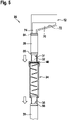
- the fluid drain assembly 20 for a battery assembly 12, such as, for example, in figure 5 is shown.
- the fluid drain assembly 20 has a fluid inlet 31, a collection chamber 32, a diaphragm 40, a labyrinth chamber 34 and a fluid outlet 36.
- the membrane 40 is provided between the collection chamber 32 and the labyrinth chamber 34 .
- the membrane 40 is set up to collect in the collection chamber 32 a coolant 14 which reaches the collection chamber 32 via the fluid inlet 31 .
- the predetermined first differential pressure can be 0.1 bar, 0.3 bar or 0.5 bar, for example. It is preferably in the range from 0.1 bar to 1.0 bar, more preferably in the range from 0.2 bar to 0.9 bar.
- the fluid drain assembly 20 has a labyrinth chamber portion 61 and a cover portion 62.
- the cover part 62 forms the collection chamber 32 in a cover part extension 64, and the cover part 62 is connected to the labyrinth chamber part 61, for example by an adhesive connection or by a screw connection.
- This design also enables easy assembly of the membrane 40 between the collection chamber 32 and the labyrinth chamber 34.
- a sealing element 42 is provided between the labyrinth chamber part 61 and the cover part 62 .
- the sealing element 42 can be an O-ring or a lip seal, for example.
- a lower lid part 63 is connected to the labyrinth chamber part 61 and the lid part 63 forms the fluid outlet 36 .
- the cover part 63 is connected, for example, to the labyrinth chamber part 61 via an adhesive connection 69, but another connection can also be selected, for example a screw connection.
- the labyrinth chamber 34 has a side wall 65, a labyrinth interior 67 and shaped elements 66.
- the shaped elements 66 extend from the side wall 65 into the labyrinth interior 67 inside. This will create a straight flow of the coolant 14 or generally a fluid through the labyrinth chamber 34 is prevented or at least reduced.
- the shaped elements 66 at least partially approach the fluid outlet 36 at least in sections as they extend from the side wall 65 into the labyrinth interior 67 .
- the shaped elements 66 protrude accordingly in the arrangement 1 at least partially, at least in sections, downwards towards the fluid outlet 36 or they are inclined in this direction.
- the coolant 14 can flow well toward the fluid outlet 36, but a flow of a fluid in the opposite direction is made more difficult.
- the shaped elements 66 are preferably at least partially flat, at least in sections. They can, for example, protrude into the labyrinth interior 67 like a springboard, but they can also be connected laterally to the side wall 65 up to their free end.
- a further advantage of the labyrinth chamber 34 is that the design of the labyrinth interior 67 prevents or at least impedes the ingress of animals from the fluid outlet 36 to the fluid inlet 31 and possibly into the battery arrangement.
- martens and other animals of the taxonomic suborder of canids can be prevented from penetrating the high-voltage battery by the labyrinth chamber 34 .
- the membrane 40 has two predetermined tearing points 44 arranged in the shape of a cross, which tear open at a predetermined differential pressure between the top and bottom of the membrane 40 and allow fluid to flow through the membrane 40 .
- the predetermined tearing points 44 can also be referred to as predetermined breaking points.
- the membrane 40 can be made of a plastic or of a thin metal sheet, for example. As a result of the rupturing, the membrane 40 can no longer transition from the open state Z2 to the closed state Z1, the transition from the closed state Z1 to the open state Z2 is therefore irreversible, and the membrane 40 is destroyed. In such a case, the membrane 40 can be replaced, for example, in a workshop.
- the membrane 40 can be formed, for example, from a rubber-elastic material, and the lines 44 arranged in the cross can be formed, for example, as continuous slots. Due to the rubber-elastic design of the material, the membrane 40 can open in the area of the lines 44 at a differential pressure, and coolant 14 can flow through. As soon as the differential pressure is no longer present, the membrane 40 can close again. As a result, after the transition from the closed state Z1 to the open state Z2, a transition of the membrane 40 to the closed state Z1 is again possible. It can also be provided that the membrane 40 can be moved into the closed state Z1 by manual actuation by a user.
- the membrane 40 is preferably set up to carry out a transition from the closed state Z1 to the open state Z2 when a predetermined quantity of coolant 14 is collected on the first side 51 of the membrane 40 .
- the hydrostatic pressure increases, and the membrane 40 opens when the hydrostatic pressure reaches a certain level.
- the membrane 40 also opens, for example, in the event of excess pressure occurring in the battery arrangement 12 as a result of degassing and can act as a safety valve for the battery arrangement 12 alone or in support of a pressure equalization element such as a bursting disk. Such an overpressure can arise, for example, if the battery arrangement is damaged.
- the membrane 40 has a round basic shape or, for example, the basic shape of an ellipse.
- FIG 3 shows a further exemplary embodiment of the fluid outflow arrangement 20.
- the basic mode of operation corresponds to the mode of operation of the fluid outflow arrangement 20 in FIG 1 .
- the labyrinth chamber 34 is made wider relative to the height of the labyrinth chamber 34.
- the labyrinth chamber part 61 is connected to the cover part 62 via a snap connection 68, and this facilitates the replacement of the membrane 40.
- the labyrinth chamber 34 has a square cross-section.
- 4 12 shows another embodiment of the membrane 40 for the fluid drain assembly 20 of FIG 3 .
- Matching the cross section of the labyrinth chamber 34 of 3 the membrane 40 has a square shape with rounded corners.
- FIG 5 shows a battery assembly 12 with the fluid drain assembly 20 attached thereto.
- the battery assembly 12 is preferably a traction battery or a high-voltage battery assembly.
- the fluid drain arrangement 20 has a bottom element 70 for the bottom area of the battery arrangement 12.
- the bottom element 70 is trough-shaped and it has a run-off slope 72 for the coolant 14 Allow coolant 14 to flow from battery assembly 12 to plenum 32 .
- the coolant 14 can, for example, get into the base element 70 and thus to the collection chamber 32 if a leak occurs in the coolant circuit of the battery arrangement 12 . This can be the case, for example, in the event of damage caused by an accident or if a leak occurs.
- the outlet slope 72 is in fluid communication with the collection chamber 32 via a hose 38.
- the outlet 36 is in fluid communication with the surroundings of a vehicle, for example, via a hose 39; it can end, for example, in the area of the underbody of the vehicle.
- the hoses 38, 39 are preferably attached via clamps 54, 55 and 56, respectively.
- the entire fluid outflow arrangement 20 can be plugged together or assembled comparatively easily for assembly.
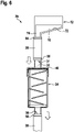
- 6 12 shows a corresponding embodiment with the battery assembly 12 and the fluid drain assembly 20 of FIG 3 .
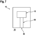
- the fluid outlet 36 is preferably in fluid connection with the environment 18 of the vehicle 10 in order to allow the coolant 14 to drain or drain into the environment of the vehicle 10 .
- the fluid drain assembly 20 is preferably positioned such that the fluid outlet 36 is below the plenum 32 to allow for good drainage or drainage by gravity. However, it is also possible to arrange the fluid drainage arrangement 20 in a different position and to align it as mentioned above only if necessary.
- the fluid inlet 31 and the fluid outlet 36 can be provided further away from the labyrinth chamber 34 by means of extension elements such as the hoses 38, 39 or the base element 70.
Landscapes
- Chemical & Material Sciences (AREA)
- Chemical Kinetics & Catalysis (AREA)
- Electrochemistry (AREA)
- General Chemical & Material Sciences (AREA)
- Engineering & Computer Science (AREA)
- Manufacturing & Machinery (AREA)
- Mechanical Engineering (AREA)
- General Engineering & Computer Science (AREA)
- Combustion & Propulsion (AREA)
- Life Sciences & Earth Sciences (AREA)
- Transportation (AREA)
- Power Engineering (AREA)
- Sustainable Energy (AREA)
- Sustainable Development (AREA)
- Secondary Cells (AREA)
Abstract
Description
- Die Erfindung betrifft eine Fluidablaufanordnung, eine Batterieanordnung und ein Fahrzeug.
- Die
DE 10 2013 014 903 A1 zeigt eine Batterie mit flüssigkeitsgekühlten Einzelzellen, bei der die Wandung des Batteriegehäuses eine Sollbruchstelle aufweist, die ein Austreten von Kühlmittel aus dem Batteriegehäuse ermöglicht. - Die
DE 10 2013 212 859 B4 zeigt ein Batteriesystem, bei dem im Falle einer Bildung von Wasserkondensat ein Fahrer informiert wird, und bei einer Detektion einer wässrigen Lösung mit Kühlmittel werden Ventile aktiviert. - Die
KR 10 2020 0 041 007 A - Die
US 2018 / 0 238 764 A1 zeigt ein Batteriepack mit einer Feuchtigkeitssammeleinheit und einer Feuchtigkeitsauslasseinheit. - Es ist daher eine Aufgabe der Erfindung, eine neue Fluidablaufanordnung, eine neue Batterieanordnung und ein neues Fahrzeug bereit zu stellen.
- Diese Aufgabe wird gelöst durch die Gegenständer der unabhängigen Ansprüche.
- Eine Fluidablaufanordnung für eine Batterieanordnung weist einen Fluideinlass, eine Sammelkammer, eine Membran, eine Labyrinthkammer und einen Fluidauslass auf, welche Membran zwischen der Sammelkammer und der Labyrinthkammer vorgesehen ist und einen geschlossenen Zustand und einen geöffneten Zustand aufweist, und welche Membran dazu ausgebildet ist, im geschlossenen Zustand ein Kühlmittel, welches über den Fluideinlass in die Sammelkammer gelangt, in der Sammelkammer zu sammeln, bis die Membran bei einem vorgegebenen ersten Differenzdruck zwischen einer der Sammelkammer zugeordneten Seite der Membran und einer der Labyrinthkammer zugeordneten Seite der Membran vom geschlossenen Zustand in den geöffneten Zustand übergeht und einen Ablauf des Kühlmittels über die Labyrinthkammer zum Fluidauslass ermöglicht. Wenn eine Batterieanordnung beispielsweise durch eine Beschädigung bei einem Unfall beschädigt wird, kann das Kühlmittel über die Fluidablaufanordnung nach außen gelangen, und hierdurch kann ein Kurschluss in der Batterieanordnung vermieden werden. Über die Labyrinthkammer kann hierbei ein ungehindertes Eindringen von Flüssigkeit, von Dreck oder von kleineren Säugetieren von der Umgebung in die Batterieanordnung verhindert oder zumindest erschwert werden. Die Membran verhindert im geschlossenen Zustand bevorzugt ein Eindringen von Luftfeuchtigkeit in die Batterieanordnung.
- Gemäß einer bevorzugten Ausführungsform ist die Membran dazu ausgebildet, nach dem Übergang vom geschlossenen Zustand in den geöffneten Zustand nicht mehr in den geschlossenen Zustand überzugehen. Dies ist beispielsweise dadurch möglich, dass die Membran durch Zerstörung in den geöffneten Zustand übergehen oder kein Rückstellelement oder keine Rückstellkraft vorgesehen sind.
- Gemäß einer bevorzugten Ausführungsform ist die Membran dazu ausgebildet, nach dem Übergang vom geschlossenen Zustand in den geöffneten Zustand wieder in den geschlossenen Zustand überzugehen. Dies ist beispielsweise durch eine Rückstellfeder, durch ein elastisches Material oder durch ein zusätzliches Rückstellelement möglich. Hierbei erfolgt der Übergang zurück in den geschlossenen Zustand bevorzugt bei einem geringeren Differenzdruck als dem ersten Differenzdruck oder durch eine manuelle Betätigung durch einen Nutzer.
- Gemäß einer bevorzugten Ausführungsform weist die Fluidablaufanordnung ein Bodenelement für eine Batterieanordnung auf, welches Bodenelement wannenförmig ist und eine Ablaufschräge für ein Kühlmittel aufweist, und welche Ablaufschräge in Fluidverbindung mit der Sammelkammer steht, um einen Ablauf eines Kühlmittels von der Batterieanordnung zur Sammelkammer zu ermöglichen. Die Ablaufschräge ermöglicht einen kontrollierten Ablauf des Kühlmittels in der Fluidablaufvorrichtung.
- Gemäß einer bevorzugten Ausführungsform steht die Ablaufschräge über einen Schlauch in Fluidverbindung mit der Sammelkammer. Schläuche haben den Vorteil, dass sie einfach montiert werden können und ggf. auch elastisch ausgebildet werden können, um kurzzeitig auftretende hohe Drücke zu verringern.
- Gemäß einer bevorzugten Ausführungsform ist der Schlauch über mindestens eine Schelle befestigt. Schellen ermöglichen stabile Verbindungen, auch unter extremen Bedingungen mit starken Erschütterungen.
- Gemäß einer bevorzugten Ausführungsform ist die Membran dazu eingerichtet, einen Übergang vom geschlossenen Zustand in den geöffneten Zustand durchzuführen, wenn auf der ersten Seite der Membran eine vorgegebene Menge an Kühlmittel gesammelt ist. Hierdurch kann sich eine unkritische Menge an Kühlmittel ansammeln, bevor die Membran in den geöffneten Zustand übergeht. Bei einer Menge, die mindestens der vorgegebenen Menge an Kühlmittel entspricht wird die Membran dagegen in den geöffneten Zustand versetzt, und das Kühlmittel kann abfließen.
- Gemäß einer bevorzugten Ausführungsform weist die Fluidablaufanordnung ein Labyrinthkammerteil und ein Deckelteil auf, welches Labyrinthkammerteil die Labyrinthkammer ausbildet, welches Deckelteil in einem Deckelteilfortsatz die Sammelkammer ausbildet, und welches Deckelteil mit dem Labyrinthkammerteil verbunden ist. Dies erleichtert die Herstellung der Labyrinthkammer und der Sammelkammer.
- Gemäß einer bevorzugten Ausführungsform ist ein Dichtelement zwischen dem Labyrinthkammerteil und dem Deckelteil vorgesehen. Hierdurch wird der Austritt von Kühlmittel an der Verbindungsstelle verhindert.
- Gemäß einer bevorzugten Ausführungsform weist die Fluidablaufanordnung zumindest bereichsweise mindestens einen Werkstoff auf aus der Werkstoffgruppe bestehend aus:
- Kunststoff,
- Aluminium, und
- Aluminiumlegierung.
- Diese Werkstoffe sind leicht und können das Kühlmittel gut leiten.
- Gemäß einer bevorzugten Ausführungsform weist die Labyrinthkammer eine Seitenwand, einen Labyrinthinnenraum und Formelemente auf, welche Formelemente sich von der Seitenwand in den Labyrinthinnenraum hinein erstrecken, um einen geradlinigen Durchfluss eines Fluids durch die Labyrinthkammer zu verhindern oder zumindest zu verringern. Dies ermöglicht einerseits einen Austritt des Kühlmittels, erschwert aber andererseits einen direkten Eintritt eines Fluids von außen in die Batterieanordnung hinein.
- Gemäß einer bevorzugten Ausführungsform nähern sich die Formelemente zumindest teilweise zumindest abschnittsweise bei ihrer Erstreckung von der Seitenwand in den Labyrinthinnenraum hinein dem Fluidauslass an. Bei einer bevorzugten Anordnung des Fluidauslasses unterhalb des Fluideinlasses kann beispielsweise ein Kühlmittel gut zum Fluidauslass fließen, ein flüssiges Medium wird dagegen daran gehindert, in umgekehrter Richtung zu fließen. Zudem wird es für Tiere schwieriger, in die Labyrinthkammer hinein zu kriechen.
- Gemäß einer bevorzugten Ausführungsform sind die Formelemente zumindest teilweise zumindest abschnittsweise flächig ausgebildet. Die flächige Ausbildung ist gut dazu geeignet, einen starken direkten Fluidfluss durch die Labyrinthkammer zu unterbinden.
- Eine Batterieanordnung weist eine solche Fluidablaufanordnung auf. Dies verringert die Gefahr, dass es bei einer Störung oder Zerstörung des Kühlsystems der Batterieanordnung durch das Kühlmittel zu einem Kurzschluss und damit zu einem größeren Schaden wie einem Brand am Fahrzeug kommt. Der Aufbau einer Kühlmittelsäule in der Batterieanordnung kann verhindert werden.
- Ein Fahrzeug weist eine solche Batterieanordnung auf. Bei Fahrzeugen ist die Sicherheit wichtig, und die Fluidablaufanordnung erhöht die Sicherheit.
- Gemäß einer bevorzugten Ausführungsform steht der Fluidauslass in Fluidverbindung mit der Umgebung des Fahrzeugs, um einen Ablauf eines Kühlmittels in die Umgebung des Fahrzeugs zu ermöglichen. Dies führt zu einer guten Trennung des Kühlmittels von der Batterieanordnung und verringert die Gefahr eines Kurzschlusses. Als Kühlmittel bzw. für einen guten Wärmetransport werden häufig Wasser-Glykol-Gemische eingesetzt, und ein Ablassen eines solchen Gemischs in einem Schadensfall ist möglich.
- Gemäß einer bevorzugten Ausführungsform ist die Sammelkammer zumindest bereichsweise oberhalb der Labyrinthkammer angeordnet. Dies erleichtert den Ablauf des Kühlmittels in einem Schadensfall.
- Weitere Einzelheiten und vorteilhafte Weiterbildungen der Erfindung ergeben sich aus den im Folgenden beschriebenen und in den Zeichnungen dargestellten, in keiner Weise als Einschränkung der Erfindung zu verstehenden Ausführungsbeispielen sowie aus den Unteransprüchen. Es versteht sich, dass die voranstehend genannten und die nachstehend noch zu erläuternden Merkmale nicht nur in der jeweils angegebenen Kombination, sondern auch in anderen Kombinationen oder in Alleinstellung verwendbar sind, ohne den Rahmen der vorliegenden Erfindung zu verlassen. Es zeigt:
-
Fig. 1 in einem Längsschnitt ein Ausführungsbeispiel einer Fluidablaufanordnung, -
Fig. 2 in einer raumbildlichen Darstellung eine Membran der Fluidablaufanordnung vonFig. 1 , -
Fig. 3 in einem Längsschnitt ein weiteres Ausführungsbeispiel einer Fluidablaufanordnung, -
Fig. 4 in einer raumbildlichen Darstellung eine Membran der Fluidablaufanordnung vonFig. 3 , -
Fig. 5 in einem Teil-Längsschnitt eine Batterieanordnung mit der Fluidablaufanordnung vonFig. 1 , -
Fig. 6 in einem Teil-Längsschnitt eine Batterieanordnung mit der Fluidablaufanordnung vonFig. 3 , und -
Fig. 7 in schematischer Darstellung ein Fahrzeug mit einer Batterieanordnung. - Im Folgenden sind gleiche oder gleich wirkende Teile mit den gleichen Bezugszeichen versehen und werden üblicherweise nur einmal beschrieben. Die Beschreibung ist figurenübergreifend aufeinander aufbauend, um unnötige Wiederholungen zu vermeiden.
-
Fig. 1 zeigt eine Fluidablaufanordnung 20 für eine Batterieanordnung 12, wie sie bspw. inFig. 5 dargestellt ist. Die Fluidablaufanordnung 20 hat einen Fluideinlass 31, eine Sammelkammer 32, eine Membran 40, eine Labyrinthkammer 34 und einen Fluidauslass 36. - Die Membran 40 ist zwischen der Sammelkammer 32 und der Labyrinthkammer 34 vorgesehen. In einem geschlossenen Zustand Z1 ist die Membran 40 dazu eingerichtet, ein Kühlmittel 14, welches über den Fluideinlass 31 in die Sammelkammer 32 gelangt, in der Sammelkammer 32 zu sammeln.
- Sobald ein vorgegebener erster Differenzdruck P51 - P52 zwischen einer der Sammelkammer 32 zugeordneten Seite 51 der Membran 40 mit dem Druck P51 und einer der Labyrinthkammer 34 zugeordneten Seite 52 der Membran 40 mit dem Druck P52 vorliegt, wechselt die Membran 40 von einem geschlossenen Zustand Z1 in einen geöffneten Zustand Z2, und das Kühlmittel aus der Sammelkammer 32 kann über die Labyrinthkammer 34 zum Fluidauslass 36 abfließen. Der vorgegebene erste Differenzdruck kann beispielsweise 0,1 bar, 0,3 bar oder 0,5 bar betragen. Er liegt bevorzugt im Bereich 0,1 bar bis 1,0 bar, weiter bevorzugt im Bereich 0,2 bar bis 0,9 bar.
- Die Fluidablaufanordnung 20 hat ein Labyrinthkammerteil 61 und ein Deckelteil 62.
- Das Deckelteil 62 bildet in einem Deckelteilfortsatz 64 die Sammelkammer 32 aus, und das Deckelteil 62 ist mit dem Labyrinthkammerteil 61 verbunden, beispielsweise durch eine Klebeverbindung oder durch eine Schraubverbindung.
- Diese Ausbildung ermöglicht auch eine einfache Montage der Membran 40 zwischen der Sammelkammer 32 und der Labyrinthkammer 34.
- Zwischen dem Labyrinthkammerteil 61 und dem Deckelteil 62 ist ein Dichtelement 42 vorgesehen. Das Dichtelement 42 kann bspw. ein O-Ring oder eine Lippendichtung sein.
- Ein unteres Deckelteil 63 ist mit dem Labyrinthkammerteil 61 verbunden, und das Deckelteil 63 bildet den Fluidauslass 36 aus. Das Deckelteil 63 ist bspw. über eine Klebeverbindung 69 mit dem Labyrinthkammerteil 61 verbunden, es kann aber auch eine andere Verbindung gewählt werden, beispielsweise eine Schraubverbindung.
- Die Labyrinthkammer 34 hat eine Seitenwand 65, einen Labyrinthinnenraum 67 und Formelemente 66. Die Formelemente 66 erstrecken sich von der Seitenwand 65 in den Labyrinthinnenraum 67 hinein. Hierdurch wird ein geradliniger Durchfluss des Kühlmittels 14 bzw. allgemein eines Fluids durch die Labyrinthkammer 34 verhindert oder zumindest verringert.
- Die Formelemente 66 nähern sich zumindest teilweise zumindest abschnittsweise bei ihrer Erstreckung von der Seitenwand 65 in den Labyrinthinnenraum 67 hinein dem Fluidauslass 36 an. Anders ausgedrückt ragen die Formelemente 66 bei der Anordnung entsprechend
Fig. 1 zumindest teilweise zumindest abschnittsweise nach unten zum Fluidauslass 36 hin bzw. sie sind in diese Richtung geneigt. Hierdurch kann das Kühlmittel 14 gut zum Fluidauslass 36 hin abfließen, ein Fluss eines Fluids in die umgekehrte Richtung wird jedoch erschwert. - Die Formelemente 66 sind bevorzugt zumindest teilweise zumindest abschnittsweise flächig ausgebildet. Sie können bspw. wie ein Sprungbrett in den Labyrinthinnenraum 67 hineinragen, sie können aber auch bis zu ihrem freien Ende lateral mit der Seitenwand 65 verbunden sein.
- Ein weiterer Vorteil der Labyrinthkammer 34 besteht darin, dass ein Eindringen von Tieren vom Fluidauslass 36 zum Fluideinlass 31 und ggf. hinein in die Batterieanordnung durch die Ausgestaltung des Labyrinthinnenraums 67 verhindert oder zumindest erschwert wird. Insbesondere Marder und andere Tiere der taxonomischen Unterordnung der Hundeartigen können durch die Labyrinthkammer 34 von einem Eindringen in die Hochvoltbatterie abgehalten werden.
- Die Fluidablaufanordnung 20 weist bevorzugt zumindest bereichsweise mindestens einen Werkstoff auf aus der Werkstoffgruppe bestehend aus:
- Kunststoff,
- Aluminium, und
- Aluminiumlegierung.
- Dabei handelt es sich um leichte und trotzdem stabile Werkstoffe, die besonders gut geeignet sind.
-
Fig. 2 zeigt eine Ausführungsform der Membran 40 vonFig. 1 . Die Membran 40 hat zwei in Kreuzform angeordnete Sollreißstellen 44, welche bei einem vorgegebenen Differenzdruck zwischen der Oberseite und Unterseite der Membran 40 aufreißen und einen Fluidfluss durch die Membran 40 ermöglichen. Die Sollreißstellen 44 können auch als Sollbruchstellen bezeichnet werden. Die Membran 40 kann bei einer solchen Ausbildung bspw. aus einem Kunststoff oder aus einem dünnen Blech ausgebildet sein. Durch das Aufreißen kann die Membran 40 nicht mehr vom geöffneten Zustand Z2 in den geschlossenen Zustand Z1 übergehen, der Übergang vom geschlossenen Zustand Z1 in den geöffneten Zustand Z2 ist also irreversibel, und die Membran 40 wird zerstört. In einem solchen Fall kann die Membran 40 bspw. in einer Werkstatt ausgetauscht werden. - In einer weiteren Ausführungsform kann die Membran 40 bspw. aus einem gummielastischen Material ausgebildet sein, und die im Kreuz angeordneten Linien 44 können bspw. als durchgehende Schlitze ausgebildet sein. Durch die gummielastische Ausbildung des Materials kann sich die Membran 40 im Bereich der Linien 44 bei einem Differenzdruck öffnen, und Kühlmittel 14 kann hindurchfließen. Sobald der Differenzdruck nicht mehr vorhanden ist, kann sich die Membran 40 wieder schließen. Im Ergebnis ist nach dem Übergang vom geschlossenen Zustand Z1 in den geöffneten Zustand Z2 wieder ein Übergang der Membran 40 in den geschlossenen Zustand Z1 möglich. Es kann auch vorgesehen werden, dass die Membran 40 durch eine manuelle Betätigung durch einen Nutzer in den geschlossenen Zustand Z1 bewegt werden kann.
- Die Membran 40 ist bevorzugt dazu eingerichtet, einen Übergang vom geschlossenen Zustand Z1 in den geöffneten Zustand Z2 durchzuführen, wenn auf der ersten Seite 51 der Membran 40 eine vorgegebene Menge an Kühlmittel 14 gesammelt ist. Durch das Ansteigen des Kühlmittels 14 in der Sammelkammer 32 erhöht sich der hydrostatische Druck, und ab einer bestimmten Größe des hydrostatischen Drucks öffnet sich die Membran 40.
- Die Membran 40 öffnet sich beispielsweise auch bei einem in der Batterieanordnung 12 durch Entgasung entstehenden Überdruck und kann allein oder unterstützend zu einem Druckausgleichselement wie einer Berstscheibe als Sicherheitsventil für die Batterieanordnung 12 wirken. Ein solcher Überdruck kann beispielsweise bei einer Beschädigung der Batterieanordnung entstehen.
- Die Membran 40 hat im Ausführungsbeispiel eine runde Grundform oder bspw. die Grundform einer Ellipse.
-
Fig. 3 zeigt ein weiteres Ausführungsbeispiel der Fluidablaufanordnung 20. Die grundsätzliche Funktionsweise entspricht der Funktionsweise der Fluidablaufanordnung 20 vonFig. 1 . Im Unterschied zur Ausführungsform vonFig. 1 ist die Labyrinthkammer 34 breiter ausgebildet relativ zur Höhe der Labyrinthkammer 34. Das Labyrinthkammerteil 61 ist mit dem Deckelteil 62 über eine Rastverbindung 68 verbunden, und dies erleichtert den Austausch der Membran 40. - Anders als beim Ausführungsbeispiel von
Fig. 1 hat die Labyrinthkammer 34 einen viereckigen Querschnitt. -
Fig. 4 zeigt eine weitere Ausführungsform der Membran 40 für die Fluidablaufanordnung 20 vonFig. 3 . Passend zum Querschnitt der Labyrinthkammer 34 vonFig. 3 hat die Membran 40 eine viereckige Form mit abgerundeten Ecken. -
Fig. 5 zeigt eine Batterieanordnung 12 mit der daran befestigten Fluidablaufanordnung 20. Die Batterieanordnung 12 ist bevorzugt eine Traktionsbatterie bzw. eine Hochvolt-Batterieanordnung. - Die Fluidablaufanordnung 20 hat ein Bodenelement 70 für den Bodenbereich der Batterieanordnung 12. Das Bodenelement 70 ist wannenförmig ausgebildet, und es hat eine Ablaufschräge 72 für das Kühlmittel 14. Die Ablaufschräge 72 steht über einen Ablauf 74 in Fluidverbindung mit der Sammelkammer 32, um einen Ablauf des Kühlmittels 14 von der Batterieanordnung 12 zur Sammelkammer 32 zu ermöglichen. Das Kühlmittel 14 kann bspw. in das Bodenelement 70 und damit zur Sammelkammer 32 gelangen, wenn eine Leckage im Kühlmittelkreislauf der Batterieanordnung 12 auftritt. Dies kann bspw. bei einer Beschädigung durch einen Unfall oder beim Auftreten einer undichten Stelle der Fall sein.
- Die Ablaufschräge 72 steht über einen Schlauch 38 in Fluidverbindung mit der Sammelkammer 32. Der Auslass 36 steht über einen Schlauch 39 bspw. in Fluidverbindung mit der Umgebung eines Fahrzeugs, er kann bspw. im Bereich des Unterbodens des Fahrzeugs enden. Die Schläuche 38, 39 sind bevorzugt über Schellen 54, 55 bzw. 56 befestigt.
- Die gesamte Fluidablaufanordnung 20 kann für die Montage vergleichsweise einfach zusammengesteckt bzw. montiert werden.
-
Fig. 6 zeigt eine entsprechende Ausführungsform mit der Batterieanordnung 12 und der Fluidablaufanordnung 20 vonFig. 3 . -
Fig. 7 zeigt ein Fahrzeug 10, welches die Batterieanordnung 12 mit der Fluidablaufanordnung 20 aufweist. Der Fluidauslass 36 steht hierbei bevorzugt in Fluidverbindung mit der Umgebung 18 des Fahrzeugs 10, um einen Abfluss bzw. Ablauf des Kühlmittels 14 in die Umgebung des Fahrzeugs 10 zu ermöglichen. - Naturgemäß sind im Rahmen der vorliegenden Erfindung vielfältige Abwandlungen und Modifikationen möglich.
- Die Fluidablaufanordnung 20 wird bevorzugt derart angeordnet, dass der Fluidauslass 36 unterhalb von der Sammelkammer 32 ist, um einen guten Ablauf oder Abfluss durch die Schwerkraft zu ermöglichen. Es ist allerdings auch möglich, die Fluidablaufanordnung 20 in einer anderen Lage anzuordnen und nur im Bedarf wie zuvor genannt auszurichten.
- Der Fluideinlass 31 und der Fluidauslass 36 können durch Verlängerungselemente wie die Schläuche 38, 39 oder das Bodenelement 70 weiter entfernt von der Labyrinthkammer 34 vorgesehen werden.
Claims (15)
- Fluidablaufanordnung (20) für eine Batterieanordnung (12), welche Fluidablaufanordnung (20) einen Fluideinlass (31), eine Sammelkammer (32), eine Membran (40), eine Labyrinthkammer (34) und einen Fluidauslass (36) aufweist,
welche Membran (40) zwischen der Sammelkammer (32) und der Labyrinthkammer (34) vorgesehen ist und einen geschlossenen Zustand (Z1) und einen geöffneten Zustand (Z2) aufweist, und welche Membran (40) dazu ausgebildet ist, im geschlossenen Zustand (Z1) ein Kühlmittel (14), welches über den Fluideinlass (31) in die Sammelkammer (32) gelangt, in der Sammelkammer (32) zu sammeln, bis die Membran (40) bei einem vorgegebenen ersten Differenzdruck zwischen einer der Sammelkammer (32) zugeordneten Seite (51) der Membran (40) und einer der Labyrinthkammer (34) zugeordneten Seite (52) der Membran (40) vom geschlossenen Zustand (Z1) in den geöffneten Zustand (Z2) übergeht und einen Ablauf des Kühlmittels (14) über die Labyrinthkammer (34) zum Fluidauslass (36) ermöglicht. - Fluidablaufanordnung (20) nach Anspruch 1, bei welcher die Membran (40) dazu ausgebildet ist, nach dem Übergang vom geschlossenen Zustand (Z1) in den geöffneten Zustand (Z2) nicht mehr in den geschlossenen Zustand (Z1) überzugehen.
- Fluidablaufanordnung (20) nach Anspruch 1, bei welcher die Membran (40) dazu ausgebildet ist, nach dem Übergang vom geschlossenen Zustand (Z1) in den geöffneten Zustand (Z2) wieder in den geschlossenen Zustand (Z1) überzugehen, insbesondere bei einem geringeren Differenzdruck als dem ersten Differenzdruck oder durch eine manuelle Betätigung durch einen Nutzer.
- Fluidablaufanordnung (20) nach einem der vorhergehenden Ansprüche, welche ein Bodenelement (70) für eine Batterieanordnung (12) aufweist, welches Bodenelement (70) wannenförmig ist und eine Ablaufschräge (72) für ein Kühlmittel (14) aufweist, und welche Ablaufschräge (72) in Fluidverbindung mit der Sammelkammer (32) steht, um einen Ablauf eines Kühlmittels (14) von der Batterieanordnung (12) zur Sammelkammer (32) zu ermöglichen.
- Fluidablaufanordnung (20) nach Anspruch 4, bei welcher die Ablaufschräge (72) über einen Schlauch (38) in Fluidverbindung mit der Sammelkammer (32) steht, wobei der Schlauch (38) bevorzugt über mindestens eine Schelle (54, 55) befestigt ist.
- Fluidablaufanordnung (20) nach einem der vorhergehenden Ansprüche, bei welcher die Membran (40) dazu eingerichtet ist, einen Übergang vom geschlossenen Zustand (Z1) in den geöffneten Zustand (Z2) durchzuführen, wenn auf der ersten Seite (51) der Membran (40) eine vorgegebene Menge an Kühlmittel (14) gesammelt ist.
- Fluidablaufanordnung (20) nach einem der vorhergehenden Ansprüche, welche ein Labyrinthkammerteil (61) und ein Deckelteil (62) aufweist, welches Labyrinthkammerteil (61) die Labyrinthkammer (34) ausbildet, welches Deckelteil (62) in einem Deckelteilfortsatz (64) die Sammelkammer (32) ausbildet, und welches Deckelteil (62) mit dem Labyrinthkammerteil (61) verbunden ist.
- Fluidablaufanordnung (20) nach Anspruch 7, bei welcher ein Dichtelement (42) zwischen dem Labyrinthkammerteil (61) und dem Deckelteil (62) vorgesehen ist.
- Fluidablaufanordnung (20) nach einem der vorhergehenden Ansprüche, bei welcher die Labyrinthkammer (34) eine Seitenwand (65), einen Labyrinthinnenraum (67) und Formelemente (66) aufweist, welche Formelemente (66) sich von der Seitenwand (65) in den Labyrinthinnenraum hinein erstrecken, um einen geradlinigen Durchfluss eines Fluids durch die Labyrinthkammer (34) zu verhindern oder zumindest zu verringern.
- Fluidablaufanordnung (20) nach Anspruch 9, bei welcher sich die Formelemente (66) zumindest teilweise zumindest abschnittsweise bei ihrer Erstreckung von der Seitenwand (65) in den Labyrinthinnenraum (67) hinein dem Fluidauslass (36) annähern.
- Fluidablaufanordnung (20) nach Anspruch 9 oder 10, bei welcher die Formelemente (66) zumindest teilweise zumindest abschnittsweise flächig ausgebildet sind.
- Batterieanordnung (12), welche eine Fluidablaufanordnung (20) nach einem der vorhergehenden Ansprüche aufweist.
- Fahrzeug (10), welches eine Batterieanordnung (12) nach Anspruch 12 aufweist.
- Fahrzeug (10) nach Anspruch 13, bei welcher der Fluidauslass (36) in Fluidverbindung mit der Umgebung (18) des Fahrzeugs (10) steht, um einen Ablauf eines Kühlmittels (14) in die Umgebung des Fahrzeugs (10) zu ermöglichen.
- Fahrzeug (10) nach Anspruch 13 oder 14, bei welchem die Sammelkammer (32) zumindest bereichsweise oberhalb der Labyrinthkammer (34) angeordnet ist.
Applications Claiming Priority (1)
| Application Number | Priority Date | Filing Date | Title |
|---|---|---|---|
| DE102021116769.8A DE102021116769B4 (de) | 2021-06-30 | 2021-06-30 | Fluidablaufanordnung für eine Batterieanordnung |
Publications (2)
| Publication Number | Publication Date |
|---|---|
| EP4113727A1 true EP4113727A1 (de) | 2023-01-04 |
| EP4113727B1 EP4113727B1 (de) | 2025-10-22 |
Family
ID=81454814
Family Applications (1)
| Application Number | Title | Priority Date | Filing Date |
|---|---|---|---|
| EP22020156.0A Active EP4113727B1 (de) | 2021-06-30 | 2022-06-10 | Batterie |
Country Status (5)
| Country | Link |
|---|---|
| US (1) | US12327886B2 (de) |
| EP (1) | EP4113727B1 (de) |
| KR (1) | KR102849851B1 (de) |
| CN (1) | CN115548602A (de) |
| DE (1) | DE102021116769B4 (de) |
Families Citing this family (1)
| Publication number | Priority date | Publication date | Assignee | Title |
|---|---|---|---|---|
| DE102023112278B4 (de) | 2023-05-10 | 2025-05-22 | Dr. Ing. H.C. F. Porsche Aktiengesellschaft | System aus drei Vorrichtungen inklusive einer Vorrichtung zum Ablassen eines Kühlmittelöls |
Citations (7)
| Publication number | Priority date | Publication date | Assignee | Title |
|---|---|---|---|---|
| DE102008034879A1 (de) * | 2008-07-26 | 2010-01-28 | Daimler Ag | Batterie, insbesondere zu einer Anwendung in einem Fahrzeug |
| DE102011015926A1 (de) * | 2011-04-02 | 2012-10-04 | Bayerische Motoren Werke Aktiengesellschaft | Batteriesystem |
| EP2760075A1 (de) * | 2013-01-25 | 2014-07-30 | MAGNA STEYR Battery Systems GmbH & Co OG | Batteriesystem mit Gehäuse |
| DE102013014903A1 (de) | 2013-09-06 | 2015-03-12 | Daimler Ag | Batterie mit Einrichtung zur Entfernung von ausgetretenem Kühlmittel aus dem Inneren des Batteriegehäuses |
| US20180238764A1 (en) | 2017-02-17 | 2018-08-23 | Hyundai Motor Company | Battery pack for electric vehicles and method of detecting cooling water leakage in battery pack for electric vehicles |
| KR20200041007A (ko) | 2018-10-11 | 2020-04-21 | 에스케이이노베이션 주식회사 | 냉각 유로 커넥터 및 이를 구비하는 배터리 팩 |
| DE102013212859B4 (de) | 2012-07-17 | 2021-01-28 | GM Global Technology Operations, LLC (n.d. Ges. d. Staates Delaware) | Systeme und Verfahren zum Abschwächen der Beschädigung einer Batterie, die durch Kühlmittellecks verursacht wird |
Family Cites Families (2)
| Publication number | Priority date | Publication date | Assignee | Title |
|---|---|---|---|---|
| JP5563490B2 (ja) * | 2011-01-12 | 2014-07-30 | プライムアースEvエナジー株式会社 | 電池モジュール |
| EP2533346A1 (de) * | 2011-06-09 | 2012-12-12 | Carl Freudenberg KG | Vorrichtung zur Entfernung von Flüssigkeit aus einer Energiespeichervorrichtung |
-
2021
- 2021-06-30 DE DE102021116769.8A patent/DE102021116769B4/de active Active
-
2022
- 2022-06-10 EP EP22020156.0A patent/EP4113727B1/de active Active
- 2022-06-23 CN CN202210715567.1A patent/CN115548602A/zh active Pending
- 2022-06-27 KR KR1020220077997A patent/KR102849851B1/ko active Active
- 2022-06-29 US US17/852,559 patent/US12327886B2/en active Active
Patent Citations (7)
| Publication number | Priority date | Publication date | Assignee | Title |
|---|---|---|---|---|
| DE102008034879A1 (de) * | 2008-07-26 | 2010-01-28 | Daimler Ag | Batterie, insbesondere zu einer Anwendung in einem Fahrzeug |
| DE102011015926A1 (de) * | 2011-04-02 | 2012-10-04 | Bayerische Motoren Werke Aktiengesellschaft | Batteriesystem |
| DE102013212859B4 (de) | 2012-07-17 | 2021-01-28 | GM Global Technology Operations, LLC (n.d. Ges. d. Staates Delaware) | Systeme und Verfahren zum Abschwächen der Beschädigung einer Batterie, die durch Kühlmittellecks verursacht wird |
| EP2760075A1 (de) * | 2013-01-25 | 2014-07-30 | MAGNA STEYR Battery Systems GmbH & Co OG | Batteriesystem mit Gehäuse |
| DE102013014903A1 (de) | 2013-09-06 | 2015-03-12 | Daimler Ag | Batterie mit Einrichtung zur Entfernung von ausgetretenem Kühlmittel aus dem Inneren des Batteriegehäuses |
| US20180238764A1 (en) | 2017-02-17 | 2018-08-23 | Hyundai Motor Company | Battery pack for electric vehicles and method of detecting cooling water leakage in battery pack for electric vehicles |
| KR20200041007A (ko) | 2018-10-11 | 2020-04-21 | 에스케이이노베이션 주식회사 | 냉각 유로 커넥터 및 이를 구비하는 배터리 팩 |
Also Published As
| Publication number | Publication date |
|---|---|
| KR20230004297A (ko) | 2023-01-06 |
| DE102021116769A1 (de) | 2023-01-05 |
| EP4113727B1 (de) | 2025-10-22 |
| KR102849851B1 (ko) | 2025-08-26 |
| CN115548602A (zh) | 2022-12-30 |
| US20230006322A1 (en) | 2023-01-05 |
| DE102021116769B4 (de) | 2025-02-27 |
| US12327886B2 (en) | 2025-06-10 |
Similar Documents
| Publication | Publication Date | Title |
|---|---|---|
| DE2854003A1 (de) | Vorrichtung zur verhinderung des rueckflusses von wasser von einer verbrauchsstelle in eine wasserversorgungsleitung | |
| DE19651117C2 (de) | Gasentlüftungsvorrichtung für einen Kraftstofftank | |
| EP3539172B1 (de) | Druckentlastungsdeckel zum abbau von in einem zellenartigen hohlraum, wie einer batteriezelle, entstehendem druck | |
| EP2566731B1 (de) | Ausgleichsbehälter für eine hydraulische kraftfahrzeugbremsanlage | |
| DE102007052706A1 (de) | Wärmetauscher | |
| WO2015067631A1 (de) | Klappenmodul | |
| DE102019210852A1 (de) | Batterie mit einer Druckabbauvorrichtung und Kraftfahrzeug mit einer solchen Batterie | |
| DE3028429C2 (de) | Hydrodynamische Drehmomentübertragungseinheit, insbesondere hydrodynamische Bremse | |
| DE102021128942B4 (de) | Entgasungseinheit, Elektronikgehäuse mit einer Entgasungseinheit und dessen Verwendung | |
| DE102021116769B4 (de) | Fluidablaufanordnung für eine Batterieanordnung | |
| DE2533164B2 (de) | Hydraulische Steuereinrichtung für ein Hydrauliksystem | |
| DE10322015B4 (de) | Dichtungsanordnung | |
| EP0890384B1 (de) | Filterkartusche für Flüssigkeit | |
| DE9407286U1 (de) | Kugelhahnkombination mit integrierter automatischer Druckentlastung | |
| EP2431648A1 (de) | Leitungselement | |
| DE102016204770A1 (de) | Ent- und/oder Belüftungsventil für einen Betriebsflüssigkeitsbehälter | |
| DE102019115547A1 (de) | Filterelement eines Filters zur Reinigung von Fluiden, Einsteckadapter und Filter | |
| EP1568932B1 (de) | Gehäusestruktur | |
| EP0133992A2 (de) | Entlüftungsventil | |
| DE102006003551B4 (de) | Filtereinrichtung zur Flüssigkeitsfilterung | |
| DE19935503B4 (de) | Filterpatrone | |
| DE2935408C2 (de) | Automatisch in Abhängigkeit von einer Druckdifferenz gesteuertes Entwässerungsventil | |
| DE102008003740A1 (de) | Vorrichtung zur Ventilbetätigung | |
| EP1130328B1 (de) | Filter- und Entleerungsvorrichtung | |
| DE202004009114U1 (de) | Reifenabdichteinheit |
Legal Events
| Date | Code | Title | Description |
|---|---|---|---|
| PUAI | Public reference made under article 153(3) epc to a published international application that has entered the european phase |
Free format text: ORIGINAL CODE: 0009012 |
|
| STAA | Information on the status of an ep patent application or granted ep patent |
Free format text: STATUS: THE APPLICATION HAS BEEN PUBLISHED |
|
| AK | Designated contracting states |
Kind code of ref document: A1 Designated state(s): AL AT BE BG CH CY CZ DE DK EE ES FI FR GB GR HR HU IE IS IT LI LT LU LV MC MK MT NL NO PL PT RO RS SE SI SK SM TR |
|
| P01 | Opt-out of the competence of the unified patent court (upc) registered |
Effective date: 20230526 |
|
| STAA | Information on the status of an ep patent application or granted ep patent |
Free format text: STATUS: REQUEST FOR EXAMINATION WAS MADE |
|
| STAA | Information on the status of an ep patent application or granted ep patent |
Free format text: STATUS: EXAMINATION IS IN PROGRESS |
|
| 17P | Request for examination filed |
Effective date: 20230704 |
|
| RBV | Designated contracting states (corrected) |
Designated state(s): AL AT BE BG CH CY CZ DE DK EE ES FI FR GB GR HR HU IE IS IT LI LT LU LV MC MK MT NL NO PL PT RO RS SE SI SK SM TR |
|
| 17Q | First examination report despatched |
Effective date: 20230801 |
|
| GRAP | Despatch of communication of intention to grant a patent |
Free format text: ORIGINAL CODE: EPIDOSNIGR1 |
|
| STAA | Information on the status of an ep patent application or granted ep patent |
Free format text: STATUS: GRANT OF PATENT IS INTENDED |
|
| INTG | Intention to grant announced |
Effective date: 20250611 |
|
| GRAS | Grant fee paid |
Free format text: ORIGINAL CODE: EPIDOSNIGR3 |
|
| GRAA | (expected) grant |
Free format text: ORIGINAL CODE: 0009210 |
|
| STAA | Information on the status of an ep patent application or granted ep patent |
Free format text: STATUS: THE PATENT HAS BEEN GRANTED |
|
| AK | Designated contracting states |
Kind code of ref document: B1 Designated state(s): AL AT BE BG CH CY CZ DE DK EE ES FI FR GB GR HR HU IE IS IT LI LT LU LV MC MK MT NL NO PL PT RO RS SE SI SK SM TR |
|
| REG | Reference to a national code |
Ref country code: CH Ref legal event code: F10 Free format text: ST27 STATUS EVENT CODE: U-0-0-F10-F00 (AS PROVIDED BY THE NATIONAL OFFICE) Effective date: 20251022 Ref country code: GB Ref legal event code: FG4D Free format text: NOT ENGLISH |
|
| REG | Reference to a national code |
Ref country code: DE Ref legal event code: R096 Ref document number: 502022005818 Country of ref document: DE |
|
| REG | Reference to a national code |
Ref country code: IE Ref legal event code: FG4D Free format text: LANGUAGE OF EP DOCUMENT: GERMAN |
|
| REG | Reference to a national code |
Ref country code: NL Ref legal event code: MP Effective date: 20251022 |
|
| PG25 | Lapsed in a contracting state [announced via postgrant information from national office to epo] |
Ref country code: NL Free format text: LAPSE BECAUSE OF FAILURE TO SUBMIT A TRANSLATION OF THE DESCRIPTION OR TO PAY THE FEE WITHIN THE PRESCRIBED TIME-LIMIT Effective date: 20251022 |
|
| PG25 | Lapsed in a contracting state [announced via postgrant information from national office to epo] |
Ref country code: ES Free format text: LAPSE BECAUSE OF FAILURE TO SUBMIT A TRANSLATION OF THE DESCRIPTION OR TO PAY THE FEE WITHIN THE PRESCRIBED TIME-LIMIT Effective date: 20251022 |
|
| REG | Reference to a national code |
Ref country code: LT Ref legal event code: MG9D |
|
| PG25 | Lapsed in a contracting state [announced via postgrant information from national office to epo] |
Ref country code: NO Free format text: LAPSE BECAUSE OF FAILURE TO SUBMIT A TRANSLATION OF THE DESCRIPTION OR TO PAY THE FEE WITHIN THE PRESCRIBED TIME-LIMIT Effective date: 20260122 |
|
| PG25 | Lapsed in a contracting state [announced via postgrant information from national office to epo] |
Ref country code: HR Free format text: LAPSE BECAUSE OF FAILURE TO SUBMIT A TRANSLATION OF THE DESCRIPTION OR TO PAY THE FEE WITHIN THE PRESCRIBED TIME-LIMIT Effective date: 20251022 Ref country code: FI Free format text: LAPSE BECAUSE OF FAILURE TO SUBMIT A TRANSLATION OF THE DESCRIPTION OR TO PAY THE FEE WITHIN THE PRESCRIBED TIME-LIMIT Effective date: 20251022 |
|
| PG25 | Lapsed in a contracting state [announced via postgrant information from national office to epo] |
Ref country code: RS Free format text: LAPSE BECAUSE OF FAILURE TO SUBMIT A TRANSLATION OF THE DESCRIPTION OR TO PAY THE FEE WITHIN THE PRESCRIBED TIME-LIMIT Effective date: 20260122 |
|
| PG25 | Lapsed in a contracting state [announced via postgrant information from national office to epo] |
Ref country code: IS Free format text: LAPSE BECAUSE OF FAILURE TO SUBMIT A TRANSLATION OF THE DESCRIPTION OR TO PAY THE FEE WITHIN THE PRESCRIBED TIME-LIMIT Effective date: 20260222 |
|
| PG25 | Lapsed in a contracting state [announced via postgrant information from national office to epo] |
Ref country code: PT Free format text: LAPSE BECAUSE OF FAILURE TO SUBMIT A TRANSLATION OF THE DESCRIPTION OR TO PAY THE FEE WITHIN THE PRESCRIBED TIME-LIMIT Effective date: 20260223 |
|
| PG25 | Lapsed in a contracting state [announced via postgrant information from national office to epo] |
Ref country code: PL Free format text: LAPSE BECAUSE OF FAILURE TO SUBMIT A TRANSLATION OF THE DESCRIPTION OR TO PAY THE FEE WITHIN THE PRESCRIBED TIME-LIMIT Effective date: 20251022 |
|
| PG25 | Lapsed in a contracting state [announced via postgrant information from national office to epo] |
Ref country code: LV Free format text: LAPSE BECAUSE OF FAILURE TO SUBMIT A TRANSLATION OF THE DESCRIPTION OR TO PAY THE FEE WITHIN THE PRESCRIBED TIME-LIMIT Effective date: 20251022 |
|
| PG25 | Lapsed in a contracting state [announced via postgrant information from national office to epo] |
Ref country code: BG Free format text: LAPSE BECAUSE OF FAILURE TO SUBMIT A TRANSLATION OF THE DESCRIPTION OR TO PAY THE FEE WITHIN THE PRESCRIBED TIME-LIMIT Effective date: 20251022 |
|
| PG25 | Lapsed in a contracting state [announced via postgrant information from national office to epo] |
Ref country code: LT Free format text: LAPSE BECAUSE OF FAILURE TO SUBMIT A TRANSLATION OF THE DESCRIPTION OR TO PAY THE FEE WITHIN THE PRESCRIBED TIME-LIMIT Effective date: 20251022 |
|
| PG25 | Lapsed in a contracting state [announced via postgrant information from national office to epo] |
Ref country code: SM Free format text: LAPSE BECAUSE OF FAILURE TO SUBMIT A TRANSLATION OF THE DESCRIPTION OR TO PAY THE FEE WITHIN THE PRESCRIBED TIME-LIMIT Effective date: 20251022 |
|
| PG25 | Lapsed in a contracting state [announced via postgrant information from national office to epo] |
Ref country code: DK Free format text: LAPSE BECAUSE OF FAILURE TO SUBMIT A TRANSLATION OF THE DESCRIPTION OR TO PAY THE FEE WITHIN THE PRESCRIBED TIME-LIMIT Effective date: 20251022 |
|
| PGFP | Annual fee paid to national office [announced via postgrant information from national office to epo] |
Ref country code: GB Payment date: 20260626 Year of fee payment: 5 |
|
| PG25 | Lapsed in a contracting state [announced via postgrant information from national office to epo] |
Ref country code: IT Free format text: LAPSE BECAUSE OF FAILURE TO SUBMIT A TRANSLATION OF THE DESCRIPTION OR TO PAY THE FEE WITHIN THE PRESCRIBED TIME-LIMIT Effective date: 20251022 |
|
| PGFP | Annual fee paid to national office [announced via postgrant information from national office to epo] |
Ref country code: AT Payment date: 20260714 Year of fee payment: 5 |
|
| PG25 | Lapsed in a contracting state [announced via postgrant information from national office to epo] |
Ref country code: EE Free format text: LAPSE BECAUSE OF FAILURE TO SUBMIT A TRANSLATION OF THE DESCRIPTION OR TO PAY THE FEE WITHIN THE PRESCRIBED TIME-LIMIT Effective date: 20251022 |
|
| PG25 | Lapsed in a contracting state [announced via postgrant information from national office to epo] |
Ref country code: CZ Free format text: LAPSE BECAUSE OF FAILURE TO SUBMIT A TRANSLATION OF THE DESCRIPTION OR TO PAY THE FEE WITHIN THE PRESCRIBED TIME-LIMIT Effective date: 20251022 |
|
| PG25 | Lapsed in a contracting state [announced via postgrant information from national office to epo] |
Ref country code: SK Free format text: LAPSE BECAUSE OF FAILURE TO SUBMIT A TRANSLATION OF THE DESCRIPTION OR TO PAY THE FEE WITHIN THE PRESCRIBED TIME-LIMIT Effective date: 20251022 |
|
| PG25 | Lapsed in a contracting state [announced via postgrant information from national office to epo] |
Ref country code: SE Free format text: LAPSE BECAUSE OF FAILURE TO SUBMIT A TRANSLATION OF THE DESCRIPTION OR TO PAY THE FEE WITHIN THE PRESCRIBED TIME-LIMIT Effective date: 20251022 |