EP4113579A2 - Lampe à décharge à haute pression, en particulier lampe à décharge à haute pression à vapeur de sodium, à capacité d'allumage améliorée - Google Patents
Lampe à décharge à haute pression, en particulier lampe à décharge à haute pression à vapeur de sodium, à capacité d'allumage améliorée Download PDFInfo
- Publication number
- EP4113579A2 EP4113579A2 EP22177024.1A EP22177024A EP4113579A2 EP 4113579 A2 EP4113579 A2 EP 4113579A2 EP 22177024 A EP22177024 A EP 22177024A EP 4113579 A2 EP4113579 A2 EP 4113579A2
- Authority
- EP
- European Patent Office
- Prior art keywords
- electrode
- antenna
- lamp
- pressure
- projection
- Prior art date
- Legal status (The legal status is an assumption and is not a legal conclusion. Google has not performed a legal analysis and makes no representation as to the accuracy of the status listed.)
- Pending
Links
Images

Classifications
-
- H—ELECTRICITY
- H01—ELECTRIC ELEMENTS
- H01J—ELECTRIC DISCHARGE TUBES OR DISCHARGE LAMPS
- H01J61/00—Gas-discharge or vapour-discharge lamps
- H01J61/02—Details
- H01J61/54—Igniting arrangements, e.g. promoting ionisation for starting
- H01J61/547—Igniting arrangements, e.g. promoting ionisation for starting using an auxiliary electrode outside the vessel
-
- H—ELECTRICITY
- H01—ELECTRIC ELEMENTS
- H01J—ELECTRIC DISCHARGE TUBES OR DISCHARGE LAMPS
- H01J61/00—Gas-discharge or vapour-discharge lamps
- H01J61/02—Details
- H01J61/04—Electrodes; Screens; Shields
- H01J61/06—Main electrodes
- H01J61/073—Main electrodes for high-pressure discharge lamps
-
- H—ELECTRICITY
- H01—ELECTRIC ELEMENTS
- H01J—ELECTRIC DISCHARGE TUBES OR DISCHARGE LAMPS
- H01J61/00—Gas-discharge or vapour-discharge lamps
- H01J61/02—Details
- H01J61/04—Electrodes; Screens; Shields
- H01J61/06—Main electrodes
- H01J61/073—Main electrodes for high-pressure discharge lamps
- H01J61/0732—Main electrodes for high-pressure discharge lamps characterised by the construction of the electrode
-
- H—ELECTRICITY
- H01—ELECTRIC ELEMENTS
- H01J—ELECTRIC DISCHARGE TUBES OR DISCHARGE LAMPS
- H01J61/00—Gas-discharge or vapour-discharge lamps
- H01J61/02—Details
- H01J61/30—Vessels; Containers
- H01J61/302—Vessels; Containers characterised by the material of the vessel
-
- H—ELECTRICITY
- H01—ELECTRIC ELEMENTS
- H01J—ELECTRIC DISCHARGE TUBES OR DISCHARGE LAMPS
- H01J61/00—Gas-discharge or vapour-discharge lamps
- H01J61/82—Lamps with high-pressure unconstricted discharge having a cold pressure > 400 Torr
- H01J61/825—High-pressure sodium lamps
Definitions
- the invention relates to a high-pressure discharge lamp, in particular a sodium vapor high-pressure discharge lamp, with improved ignitability.
- HID high-intensity discharge lamps
- They are used for a wide variety of applications, for example for lighting outdoor areas or in projectors. In addition, they are also used in horticulture to illuminate plants, for example to illuminate greenhouses. They typically have a burner unit with a discharge vessel enclosing a discharge space. Two electrodes are arranged opposite one another in this discharge vessel, the electrodes each having an electrode carrier with an electrode tip. At least one of the electrodes, for example a first electrode, has an electrode coil, which comprises a wire wound around the electrode carrier, in a tip area adjacent to the electrode tip in the discharge space.
- An ionizable lamp filling containing various fillers is enclosed in the discharge space of the discharge vessel and generates radiation with specific wavelengths when excited.
- Typical fillers are selected from mercury, compounds of other metals, especially metal halides, and noble gases.
- the high-pressure discharge lamps emit radiation with a desired wavelength or with desired wavelength ranges. In this way, the lamps can be optimized for different applications.
- sodium vapor high-pressure discharge lamps are advantageous used, which contain as fillers sodium, mercury and inert gas such as xenon and optionally other metals such as thallium, indium, scandium, rare earths or their compounds.
- Such lamps radiate particularly intensely in wavelength ranges that can be used for photosynthesis by plants, i.e. in particular in a wavelength range from 380 nm to 780 nm.
- the number of photons emitted per unit of time that are in this photosynthetically usable wavelength range is determined by the so-called PAR value (from the English: photosynthetically active radiation ) specified.
- a conventional generation of the generic high-pressure discharge lamps had, for example, a PAR value of 1950 ⁇ mol /s at a gas filling pressure of 350 mbar. Without supporting measures, these lamps already had excellent ignitability and ignited without any problems.
- PAR values of 2100 ⁇ mol /s or even 2150 ⁇ mol /s were achieved. To do this, the gas filling pressure had to be increased to around 520 mbar, which meant that these lamps no longer ignited easily.
- Various techniques have therefore been developed to improve the ignitability of the lamps.
- generic high-pressure discharge lamps can have an antenna that is routed along an outside of the discharge vessel and can be subjected to voltage, which antenna is typically made of a conductive material and which reduces the ignition voltage required for the lamp.
- the antenna can be designed in the form of a wire or as an ignition strip applied to the discharge vessel. It can be an active or a passive antenna.
- An active antenna is electrically connected to an electrode of the lamp, while there is no direct electrical connection between a passive antenna and the electrodes.
- a passive antenna can, for example, be capacitively connected to the ignition voltage, as shown in EP 2 301 063 B1 is described for a so-called hybrid antenna.
- a further possibility for reducing the ignition voltage lies in the use of a capacitor unit, for example a triple capacitor such as the "Triple Capacitor" developed by the applicant.
- the object of the present invention to specify a high-pressure discharge lamp with improved ignitability.
- the high-pressure discharge lamp should be operable without major design changes and in particular with conventional lampholders and ballasts.
- the high-pressure discharge lamp should function reliably with the highest possible PAR value and, in particular, should ignite reliably.
- the solution is achieved with a generic high-pressure discharge lamp mentioned at the outset (also simply referred to as “lamp” below) in that the first electrode has a projection which protrudes over the outer circumference of the electrode filament in the direction of the antenna.
- the projection according to the invention therefore protrudes over the electrode and thus also over the electrode coil of the electrode. This does not necessarily mean that the projection has to start from the outer circumference of the electrode coil. Rather, the invention also includes that the projection is located adjacent to the electrode coil in the direction of longitudinal extent of the electrode carrier and has a greater length than the extent of the electrode coil in the radial direction, so that it protrudes beyond the outer circumference of the electrode coil.
- the projection extends at least partially in the lateral direction (ie from an inner region of the discharge vessel of the burner unit outwards towards the inner wall of the same).
- the projection according to the invention reduces the distance between the electrode and the antenna or partially bridges it.
- the protrusion In order to be effective, the protrusion must be of any significant length. Surface irregularities of the electrode and specifically of the electrode coil are therefore not to be understood as a projection within the meaning of the invention. Accordingly, the length by which the projection protrudes beyond the outer circumference of the electrode coil is expediently at least half the thickness of the electrode coil in a radial direction starting from the longitudinal axis of the electrode carrier, preferably at least the thickness of the electrode coil.
- the projection expediently protrudes by at least half the diameter, preferably at least the diameter of the wire from which the electrode coil is formed.
- the projection expediently protrudes by at least half the diameter, preferably at least the diameter of the wire from which the electrode coil is formed.
- the invention can be used in all high-pressure discharge lamps with an antenna, even when the gas filling pressure is lower than the problematic range mentioned at the outset, and can contribute to improving their ignitability.
- high pressure discharge lamps are selected from the group consisting of a metal halide lamp and a high-pressure sodium vapor lamp, in particular a high-pressure sodium vapor lamp with a gas filling pressure of more than 360 mbar, a high-pressure sodium vapor lamp with a gas filling pressure of more than 470 mbar, a high-pressure sodium vapor lamp with a gas filling pressure of more than 580 mbar, a high-pressure sodium vapor lamp with a gas filling pressure of more than 700 mbar and a high-pressure sodium vapor lamp with a gas filling pressure of 580 mbar to 850 mbar.
- a sodium high-pressure discharge lamp for plant lighting is particularly preferred.
- the projection according to the invention is used on the first electrode.
- both electrodes can also have the projection.
- the first electrode is expediently the one that is connected to the neutral conductor of the ballast, and the second electrode is preferably the one at which the ignition voltage is applied.
- the projection according to the invention serves to shorten the distance between the first electrode and antenna in order to lower the ignition voltage.
- the projection is therefore expediently electrically conductive, ie it contains an electrically conductive material or is made entirely of such a material. It is preferably the same material from which the electrode and/or the electrode coil are made.
- a typical material is a refractory metal such as tungsten or thoriated tungsten.
- the high-pressure discharge lamp has two electrodes, each of which has an electrode carrier with an electrode tip.
- the electrode tips lie opposite one another in the discharge space, so that an arc can form between them during operation of the high-pressure discharge lamp.
- At least a first of the electrodes is designed as a helical electrode in a manner known per se.
- an electrode coil is attached, which is made of a wire wound around the electrode carrier. “Wrapped around the electrode carrier” does not necessarily mean that the electrode coil has to be wound around the electrode carrier during its production. Rather, the electrode coil can also be wound independently of the electrode carrier and then pushed onto the electrode carrier.
- the coil electrode preferably consists only of an electrode carrier and an electrode coil.
- the electrode tip at which the arc attaches when the lamp is in operation—is formed by the exposed end of the electrode carrier protruding into the discharge space.
- the electrode tip is therefore part of the electrode carrier and is in one piece with it. Accordingly, the coil electrode does not have a separate electrode body attached to the tip of the electrode carrier and protruding from the tip of the electrode carrier in the direction of the opposite electrode.
- the front, the end of the electrode coil lying towards the electrode tip is usually at a distance from the electrode tip, ie it is set back somewhat from the tip. This end area of the electrode carrier, in which it is exposed and not surrounded by an electrode coil, is referred to as the "free tip area".
- the "free tip area” is a portion of the tip area in which the electrode coil is attached.
- the tip area of the electrode carrier extends from the electrode tip to a central area of the electrode carrier and ends at a distance from the rear end area of the electrode carrier, with which the latter is held in a sealing area of the discharge vessel.
- the electrode carrier is held on the discharge vessel in a manner known in the prior art, for example by fastening the rear end of the electrode carrier to a niobium cap and soldering the cap to the tube of the discharge vessel.
- the length of the tip area can be, for example, 10 to 80%, preferably 20 to 75%, particularly preferably 25 to 70% and in particular 30 to 60% of the total length of the electrode carrier.
- the electrode coil and the projection of the first electrode are arranged in this tip area.
- the shape of the projection is not particularly defined, as long as it is suitable for reducing the starting voltage of the lamp and, in particular, for ensuring that electrons jump between the projection and the antenna. This works particularly well if the projection is concentrated in the direction of the antenna.
- the projection is therefore preferably rod-shaped or strip-shaped and/or tapered in the direction of the antenna.
- the projection can be located anywhere along the tip area of the electrode support rod. However, if the protrusion is too close to the tip of the electrode carrier, the protrusion can impede the formation of a stable arc, which in turn can lead to flickering of the lamp during operation.
- the projection it is preferable to arrange the projection in a region in which it does not hinder the formation of a stable arc discharge during lamp operation.
- the projection according to the invention thus performs its function only during the ignition of the lamp, while it no longer has any function during normal lighting operation and in particular does not serve as a starting point for the arc.
- the projection is therefore particularly preferably set back as seen from the electrode tip and is arranged in particular in a rear end region of the electrode filament pointing away from the electrode tip or, as seen from the electrode tip, in the immediate vicinity behind the electrode filament.
- the projection is preferably located in the rear half of the electrode coil, viewed from the electrode tip, and particularly preferably in its rear third.
- a distance between the projection and the electrode tip in the direction of the electrode carrier is, for example, at least 2 mm and preferably at least 4 mm.
- the length along the electrode carrier is measured between the electrode tip and a projection of the point of the projection that is closest to the electrode tip onto the electrode carrier.
- the projection does not necessarily have to start from the electrode coil, but can be arranged adjacent to, expediently directly adjacent to, the electrode coil.
- the projection can be designed as a part that is separate from the electrode coil. This is expediently attached to the electrode carrier, for example by soldering or welding. It is also possible to mold the projection onto the electrode carrier during the production thereof, so that the projection is preferably formed in one piece with the electrode carrier.
- the projection is preferably in the form of a rod or strip and protrudes radially from the electrode carrier.
- the projection is formed as part of the electrode coil. It is particularly preferred that the projection is formed from a section of the wire of the electrode coil and is therefore in particular in one piece with the electrode coil. In principle, there is the possibility of forming the projection from an end section of the filament wire or from a middle section of the filament wire lying within the end sections. In both cases, the piece of wire from which the projection is formed is not wound around the electrode carrier like the other sections of the coil wire, but is bent outwards in such a way that it protrudes beyond the outer circumference of the electrode coil.
- an end section of the wire is expediently used to form the projection, which end section lies in the rear area of the electrode coil, which is remote from the electrode tip. Accordingly, the projection in the rear region of the electrode filament protrudes beyond its outer circumference, which has the advantage already mentioned that the projection does not impede the formation of a stable arc during lighting operation.
- the electrode coil has an inner coil layer and an outer coil layer and, in exceptional cases, more than two coil layers.
- All helical layers are preferably wound from a continuous wire, ie are formed in one piece. Helical layers lying directly one on top of the other are preferably wound with different, ie opposite, directions of rotation.
- the inner filament layer is usually wound from the rear end of the filament in the direction of the electrode tip, and the outer filament layer is then wound back up from the electrode tip side the inner turning position.
- the end sections of the coil wire are then both in the rear region of the electrode coil pointing away from the electrode tip and thus on the side preferred for the formation of the projection.
- each of these end sections can be used for the formation of the projection, theoretically both end sections could also be common, although this is not preferred.
- the projection can be produced most easily by bending the end section of the outer spiral layer in the direction of the antenna.
- the projection can also be formed from a middle region of the coiled wire.
- the projection is preferably designed as a wire loop. For this, part of the wire of the electrode coil is not routed directly along the electrode carrier or a lower-lying coil layer, but is first routed away from the electrode carrier, then bent over and fed back to the electrode carrier. Subsequent to the wire loop, the wire can then be further wound as an electrode coil.
- the purpose of the projection is to reduce the distance between the electrode or the electrode filament and the antenna as much as possible, in order to make it easier for electrons to escape and to reduce the ignition voltage. This is all the easier to achieve the closer the free end of the projection is to the antenna. Since the antenna is on the outside of the discharge vessel, but the projection is inside the discharge vessel, a minimum distance between the projection and the antenna is achieved by bringing the free end of the projection as close as possible to the inside of the discharge vessel in an area opposite the antenna. In order to avoid damage to the discharge vessel, the projection should not touch the discharge vessel and should at least maintain a small distance from the inside of the discharge vessel.
- the distance between the antenna and the free end of the projection is thus essentially determined by the wall thickness of the discharge vessel and is only slightly greater than this when it is as close as possible. How long the projection has to be in order to meet these requirements depends largely on the type of high-pressure discharge lamp and its dimensions.
- exemplary lengths with which the projection protrudes beyond the outer circumference of the electrode coil are in a range from 0.5 mm to 1.8 mm, preferably 0.8 mm to 1.5 mm. in particular 1 mm to 1.3 mm.
- the antenna is basically designed as is customary in the prior art and consists of a conductive material, for example a metal wire.
- an ignition strip made of conductive material can be applied to the outside of the discharge vessel of the burner unit.
- the antenna is therefore designed to be integrated into the discharge vessel.
- the antenna runs at least over a partial region along the outside of the discharge vessel, in particular in the longitudinal direction of the lamp from the first to the second electrode and preferably essentially completely along the longitudinal direction of the light-emitting part of the discharge vessel.
- the antenna can be designed as an active or as a passive antenna. It is particularly preferably a passive antenna, which means that it is not directly electrically connected to one of the electrodes.
- the antenna is capacitively or resistively coupled to the electrodes, as is already the case in principle in the initially mentioned EP 2 301 063 B1 is described.
- the antenna and the electrode are preferably coupled via a capacitor unit.
- the antenna on the side of the first electrode is capacitively coupled to the lamp ignition voltage via a capacitor unit, in particular a triple capacitor such as the applicant's “Triple Capacitor”.
- the capacitor unit comprises, for example, an inner conductor, in particular a niobium pin, which is surrounded by a dielectric, in particular a ceramic tube.
- An outer conductor is arranged as a coil around the outside of the dielectric, for example a coil of tungsten wire.
- the inner conductor is electrically conductively connected to the electrode, in particular the first electrode.
- the outer conductor is electrically connected to the antenna.
- this structure consisting of inner conductor, dielectric and outer conductor is implemented in triplicate and connected in parallel to one another.
- the capacitor unit means that the high-frequency ignition pulse is only weakened.
- the capacity of the capacitor and thus the desired ignition pulse can be adjusted to one another by suitably matching the dimensioning of the dielectric, specifically the thickness of the material, the filament and the pin. In this way, the ignition voltage for starting the lamp is reduced and the formation of the arc is supported without a current flowing through the antenna that would bypass the arc and could even lead to damage or destruction of the material of the discharge vessel.
- the antenna For fastening the antenna to the discharge vessel and/or for coupling the antenna to the ignition voltage, the antenna has what is known as an antenna ring at least on the side of the first electrode and preferably on both of its sides. This connects seamlessly to the main body of the antenna running in the longitudinal direction of the discharge vessel and preferably consists of the same material as the main body, in particular it is formed in one piece with it.
- the antenna ring preferably completely encircles the discharge vessel in its circumferential direction.
- a first antenna ring is advantageously arranged in the area of the first electrode and thus also runs around the first electrode in the circumferential direction, preferably in one plane perpendicular to the longitudinal direction of the lamp.
- the distance between the projection and the antenna does not change, for example as a result of a rotation of the electrode together with the projection about a longitudinal central axis of the lamp.
- the corresponding antenna ring therefore simplifies assembly and ensures reliable operation of the high-pressure discharge lamp according to the invention.
- the free end of the projection comes as close as possible to the antenna and here specifically to the antenna ring arranged on the outer wall of the discharge vessel, the distance between the two essentially corresponds to the wall thickness of the discharge vessel.
- the projection In order to keep the distance between the free end of the projection and the antenna ring as small as possible, the projection must not only be brought closer to the antenna ring in a radial direction with respect to the electrode carrier, but also the axial positions of the antenna ring and the projection along the longitudinal direction of the electrode carrier must be adjusted be coordinated. As a rule, however, it is not necessary for the axial positions to match exactly in order to improve the ignitability of the lamp. Studies have shown that it is sufficient if the first antenna ring adjacent to the first electrode is arranged in an area whose width in a longitudinal direction of the lamp running through the electrode supports is within a range of up to ⁇ 4 mm in relation to the free end of the projection .
- the deviation of the antenna ring in the axial direction in relation to the free end of the projection can be up to 4 mm both in the direction of the electrode tip and in the direction away from it, resulting in a strip of 8 mm width in which the projection of the first electrode can be positioned.
- This tolerance range considerably simplifies the assembly of the lamp according to the invention.
- the range is preferably up to ⁇ 3 mm and in particular at most ⁇ 2 mm.
- the above description essentially related to the configuration of the first electrode.
- the first electrode In order to achieve the improvement in ignitability intended by the invention, it is sufficient if only one of the electrodes, referred to here as the first electrode, has the projection projecting beyond the electrode coil.
- a conventional electrode As the second electrode, ie an electrode without a projection.
- the second electrode also has a projection, which, however, does not necessarily have to contribute to improving the ignitability.
- a second antenna ring can be provided, which is formed integrally with the remaining portions of the antenna and by leading the antenna around the outer periphery of the discharge vessel at a distance from the first antenna ring.
- the second antenna ring is designed in particular like the first antenna ring. To avoid repetition, reference is made to the statements on the first antenna ring.
- the second antenna ring can be arranged in the area of the second electrode.
- the second antenna ring can be positioned relative to the second electrode and in particular to a projection on the second electrode in the same way as between the first antenna ring and the first electrode.
- the second antenna ring is arranged along the longitudinal direction of the lamp essentially at the same height with a projection on the second electrode. In this case, the distance between the protrusion of the second electrode and the antenna is substantially the same as that between the first electrode and the first antenna.
- the ignition voltage is preferably applied to the second electrode, while the first electrode is preferably connected to the neutral conductor.
- the first electrode is preferably connected to the neutral conductor.
- the distance between the second electrode and in particular the projection of the second electrode and the antenna is accordingly greater than the corresponding distance between the projection of the first electrode and the antenna. Specifically, this can be done in such a way that the second antenna ring is arranged at a comparatively large distance from the electrode coil and in particular from the projection of the second electrode.
- the second antenna ring is offset further outwards compared to the first antenna ring and is arranged in the region of the outer end of the discharge vessel adjacent to the second electrode. It is preferred that the second antenna ring is offset along the longitudinal direction of the lamp by at least 2 mm, preferably by at least 4 mm and particularly preferably by at least 6 mm relative to the projection of the second electrode, in particular offset in the direction of the end of the discharge vessel. This way will ensures that the ignition takes place correctly and without a short circuit and that an arc is formed between the two electrodes.
- the structure of the high-pressure discharge lamp according to the invention corresponds to that known from the prior art, apart from the electrode design according to the invention. This applies in particular to the basic structure of the lamp and the materials used.
- the discharge vessel of the burner unit of the high-pressure discharge lamp is preferably made of ceramic, but can also be made of quartz glass. It typically has an inner diameter of between 5 and 15 mm, preferably between 8 mm and 10 mm.
- the burner unit is in turn arranged in an outer bulb, which is preferably made of quartz glass.
- the outer bulb can be socketed on one or two sides.
- the high-pressure discharge lamp according to the invention is preferably designed for use in conventional lampholders and, in particular, also with conventional ballasts. It is preferably designed for plant lighting, in particular for horticulture, for example use in greenhouses.
- FIG 1 shows a high-pressure discharge lamp 5, specifically a sodium vapor high-pressure discharge lamp for lighting plants.
- the high-pressure discharge lamp 5 comprises an outer bulb 50, which is made of quartz glass, for example, and in which a burner unit 1 is accommodated.
- the outer bulb 50 comprises a seal 52, for example a pinch, at both ends along the longitudinal direction L of the lamp, which seals the outer bulb 50 in a gas-tight manner and through which external connections 53 for making electrical contact with the high-pressure discharge lamp 5 are routed to the outside .
- a getter 51 is arranged in the outer bulb 50 in order to remove impurities in the outer bulb 50 .
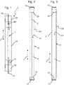
- the burner unit 1 comprises a discharge vessel 10 made of ceramic, for example, which is enlarged in FIGS Figures 2 and 3 is shown. According to the view figure 2 is doing opposite to the view from figure 3 rotated 90° to the left.
- the discharge vessel 10 is essentially in the form of a hollow cylinder and encloses a discharge space 11 which is sealed gas-tight at its front ends with a seal 12 in each case, which in turn each have a feedthrough for an electrode connection.
- the wall of the discharge vessel 10 made of ceramic for example, has an outside 100 and an inside 101 which are spaced apart from one another in accordance with the wall thickness of the discharge vessel 10 .
- An antenna 2 is arranged on the outside 100 of the discharge vessel 10 .
- the antenna 2 is made of a conductive material that is applied to the outside 100 of the discharge vessel 10, and its main body extends in the longitudinal direction L of the high-pressure discharge lamp 5. In the region of the ends of the discharge vessel 10, the antenna has a first antenna ring 20 and a second Antenna ring 21 made of conductive material.
- the antenna 2 including the antenna rings 20, 21 is designed in one piece, so that the antenna rings 20, 21 are electrically conductively connected to one another.
- Such antennas 2 are known in principle in the prior art.
- the first ring antenna 20 is arranged further away from the adjacent end of the discharge vessel 10 and is moved in the direction of the center of the discharge vessel than the second ring antenna 21 is from the end of the discharge vessel assigned to it 10. This is explained in more detail below.
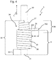
- FIG 4 shows an electrode using the example of the first electrode 3.
- the second electrode 4 (see Figures 7 and 8 ) can be designed in exactly the same way as the first electrode 3.
- the first electrode 3 comprises an electrode carrier 30 with an electrode tip 31.
- the electrode carrier 30 is a one-piece rod, one end of which forms the electrode tip 31.
- a wire 33 is wound as an electrode coil 34 on the electrode carrier 30 in a tip region 32 .
- the electrode carrier 30 and also the wire 33 forming the electrode coil 34 are made of tungsten, for example.
- the electrode coil 34 consists of a continuous, one-piece wire 33 which is wound in two coil layers 37, 38 around the electrode carrier 30 in the exemplary embodiment shown.
- the wire 33 forms an inner spiral layer 37, which in the exemplary embodiment shown consists of twelve turns wound from a central region of the electrode carrier 30 in the direction of the electrode tip 31 with a clockwise direction of rotation, and an outer spiral layer wound in opposite directions onto the inner spiral layer 37 from the electrode tip 38, which in the embodiment shown consists of nine turns with a left-hand direction of rotation.
- the tip area 32 in which the electrode coil 34 is located, extends from the electrode tip 31 in the direction of the rear end of the electrode carrier 30 and here takes up about two-thirds of the total length of the electrode carrier.
- the electrode coil 34 is set back in relation to the electrode tip 31, so that an end region of the electrode carrier 30 is exposed in a free tip region 32-1 and is not wrapped with the electrode coil.
- the aim is for the arc to attach continuously to the electrode tip 31 during operation of the high-pressure discharge lamp 5. If this is not the case, the lamp will flicker during operation. For this reason, the electrode coil is usually set back somewhat in relation to the electrode tip on the electrode carrier. It is also avoided in the prior art that there are projections that protrude beyond the electrode coil 34 since they can cause the arc to start on them instead of on the electrode tip 31 . Contrary to previous efforts, the electrode 3 has a projection 35 which protrudes by a length E beyond the electrode coil 34 .
- the length E is measured as the distance of the outermost point of the projection 35 from the outer circumference of the electrode coil 34 indicated by the dashed line, measured in the radial direction, starting from the central axis of the electrode carrier 30 (cf. also figure 5 ).
- the projection 35 is formed by the end section 351 of the wire 33 of the outer spiral layer 38 .
- a piece of the wire 33 is left projecting outward. This piece of wire 33 is not wound around the electrode carrier 30 and onto the inner coil layer 37 and therefore protrudes from the electrode coil 34 with its free end 352 .
- the projection 35 reduces the distance from the electrode 3 to the antenna 2 by the length E of the projection 35, measured in the radial direction R, starting from the central axis M of the electrode carrier 30 between the outer circumference of the electrode coil 34 and the outermost point of the projection 35.
- the length E is greater than the diameter C of the electrode coil 34 in the radial direction R.
- the greater proximity of the electrode 3 to the antenna facilitates the escape of electrons, which in turn, the ignitability of the high-pressure discharge lamp 5 is improved.
- the projection 35 is arranged at a distance A from the electrode tip 31 in the longitudinal direction L of the high-pressure discharge lamp 5 .
- the projection 35 is still in the tip area 32, in the area of the electrode coil 34, it is in a central area of the electrode carrier 30, here at about half its length. In relation to the electrode coil 34, the projection 35 is located in a rear end region 36 thereof, at about one third of the total length of the electrode coil in the longitudinal direction L, and at the end of the outer coil layer 38 facing away from the electrode tip 31.
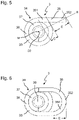
- the Figures 5 and 6 show two different embodiments of the projection 35 in an axial view of the electrode 3.
- the projection 35 is formed by an end section 351 of the wire 33, which protrudes with its free end 352 from the electrode coil 34 and the electrode carrier 30 away.
- the projection 35 protrudes tangentially. In the radial direction, it shortens the distance between the electrode 3 and the antenna 2 by the length E, as already referred to in FIG figure 4 described.
- figure 6 12 shows an alternative embodiment in which the projection 35 is formed by a wire loop 350 of the wire 33.
- a center piece of the wire 33 is formed into a wire loop 350 away from the inner spiral layer 37 and guided back to it again.
- the wire 33 then ends after it has been returned to the inner spiral layer 37.
- it could also be further wound around the inner spiral layer 37 in further turns.
- the loop-shaped projection 35 also protrudes by the length E in the radial direction over the electrode 3 and thereby shortens the distance between the electrode 3 and the antenna 2.
- the Figures 7 and 8 show the burner unit 1 with electrodes 3, 4 built into the discharge vessel 10.
- Analogously to FIGS Figures 2 and 3 is the discharge vessel 10 between the Figures 7 and 8 shown rotated by 90°.
- the electrodes 3, 4 are identical to each other, arranged in the discharge space 11 of the burner unit 1 and each with a contact pin 39, 49 through the seal 12 is brought out of the discharge vessel 10, electrically contactable.
- the first antenna ring 20 of the antenna 2 is arranged along the longitudinal direction L of the high-pressure discharge lamp 5 at the level of the projection 35 of the first electrode 3 .
- the second antenna ring 21 of the antenna 2 is arranged away from the projection 45 of the second electrode 4 along the longitudinal direction L of the high-pressure discharge lamp 5 and is arranged offset outwards towards the end of the discharge vessel 10 adjacent to the second electrode 4 . In this way, a coupling between the second antenna ring 21 and the second electrode 4 is avoided, and short circuits are prevented.
- the first electrode 3 is designed to be connected to the neutral conductor of a ballast.
- a capacitor unit 390 in the present embodiment a triple capacitor such as a "Triple Capacitor" by the applicant.
- the antenna 2 is capacitively coupled to the ignition voltage on the side of the first electrode 3 via the capacitor unit 390 .
- the capacitor unit is in the form of a triple capacitor and comprises three capacitor elements which are connected in parallel with one another and each have an inner conductor, a dielectric and an outer conductor.
- the inner conductor is, for example, a niobium pin surrounded by a ceramic tube that forms the dielectric.
- the outer conductor is arranged as a coil, for example made of tungsten wire, around the outside of the dielectric.
- the inner conductor is electrically conductively connected to the first electrode.
- the outer conductor in turn is electrically conductively connected to the antenna.
- the capacitor unit means that the high-frequency ignition pulse is only weakened.
- the capacitance of the capacitor and thus the desired ignition pulse can be adjusted to one another by suitably matching the dimensioning of the dielectric, here specifically the wall thickness of the ceramic tube, the filament and the pin. In this way, the ignition voltage for starting the lamp is reduced and the formation of the arc is supported without a current flowing through the antenna that would bypass the arc and could lead to damage or destruction of the material of the discharge vessel.
- capacitor unit 390 in connection with the antenna 2 and the projection 35 leads overall to a significant improvement in the ignitability of the high-pressure discharge lamp 5, which enables it to be operated at an increased gas filling pressure.
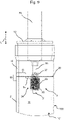
- FIG 9 an enlarged detailed view of that end of the burner unit 1 in which the first electrode 3 is arranged is shown.
- the first Antenna ring 20 is arranged around the projection 35 within a width W in the longitudinal direction L of the lamp.
- the width W is, for example, 2 mm on each side of the projection 35 in the longitudinal direction L. This ensures that the projection 35 is as close as possible to the antenna 2, and specifically to the first antenna ring 20 here.
- the distance D from the electrode 3 to the antenna 2 is therefore reduced by the length E of the projection 35. Due to this reduced distance D, the high-pressure discharge lamp 5 ignites with an ignition voltage that can be provided by conventional lampholders and ballasts, even if a very high gas inflation pressure to achieve high PAR.
Landscapes
- Discharge Lamps And Accessories Thereof (AREA)
Applications Claiming Priority (1)
| Application Number | Priority Date | Filing Date | Title |
|---|---|---|---|
| DE102021206702.6A DE102021206702A1 (de) | 2021-06-28 | 2021-06-28 | Hochdruckentladungslampe, insbesondere natriumdampf-hochdrucklampe, mit verbesserter zündfähigkeit |
Publications (2)
| Publication Number | Publication Date |
|---|---|
| EP4113579A2 true EP4113579A2 (fr) | 2023-01-04 |
| EP4113579A3 EP4113579A3 (fr) | 2023-03-22 |
Family
ID=81878153
Family Applications (1)
| Application Number | Title | Priority Date | Filing Date |
|---|---|---|---|
| EP22177024.1A Pending EP4113579A3 (fr) | 2021-06-28 | 2022-06-02 | Lampe à décharge à haute pression, en particulier lampe à décharge à haute pression à vapeur de sodium, à capacité d'allumage améliorée |
Country Status (3)
| Country | Link |
|---|---|
| US (1) | US20220415642A1 (fr) |
| EP (1) | EP4113579A3 (fr) |
| DE (1) | DE102021206702A1 (fr) |
Citations (1)
| Publication number | Priority date | Publication date | Assignee | Title |
|---|---|---|---|---|
| EP2301063B1 (fr) | 2008-07-10 | 2013-10-23 | Koninklijke Philips N.V. | Lampe à décharge à vapeur de sodium haute pression avec antenne hybride |
Family Cites Families (6)
| Publication number | Priority date | Publication date | Assignee | Title |
|---|---|---|---|---|
| DE3205401A1 (de) | 1982-02-16 | 1983-08-25 | Patent-Treuhand-Gesellschaft für elektrische Glühlampen mbH, 8000 München | Hochdruckentladungslampe |
| JP3562271B2 (ja) * | 1997-11-07 | 2004-09-08 | ウシオ電機株式会社 | ショートアークランプ |
| DE29722583U1 (de) | 1997-11-20 | 1998-03-12 | Eggers, Thomas, 88525 Dürmentingen | Elektrode für Entladungslampen |
| US8174194B2 (en) * | 2007-08-06 | 2012-05-08 | Seiko Epson Corporation | Discharge lamp, light source device and projector |
| JP2012160306A (ja) * | 2011-01-31 | 2012-08-23 | Ushio Inc | ショートアーク型放電ランプ |
| US10074532B1 (en) * | 2017-03-07 | 2018-09-11 | Eye Lighting International Of North America, Inc. | Semi-active antenna starting aid for HID arc tubes |
-
2021
- 2021-06-28 DE DE102021206702.6A patent/DE102021206702A1/de active Pending
-
2022
- 2022-06-02 EP EP22177024.1A patent/EP4113579A3/fr active Pending
- 2022-06-24 US US17/808,686 patent/US20220415642A1/en active Pending
Patent Citations (1)
| Publication number | Priority date | Publication date | Assignee | Title |
|---|---|---|---|---|
| EP2301063B1 (fr) | 2008-07-10 | 2013-10-23 | Koninklijke Philips N.V. | Lampe à décharge à vapeur de sodium haute pression avec antenne hybride |
Also Published As
| Publication number | Publication date |
|---|---|
| DE102021206702A1 (de) | 2022-12-29 |
| EP4113579A3 (fr) | 2023-03-22 |
| US20220415642A1 (en) | 2022-12-29 |
Similar Documents
| Publication | Publication Date | Title |
|---|---|---|
| EP0391283B1 (fr) | Lampe à décharge à haute pression à double culot | |
| DE29506356U1 (de) | Hochleistungs-Sofitten-Bogenlampe | |
| DE69318638T2 (de) | Universelle Metallhalogenidlampe | |
| DE69903782T2 (de) | Einheit mit einer kurzbogen-entladungslampe mit anlaufantenne | |
| DE2815014C2 (de) | Hochdrucknatriumdampfentladungslampe | |
| EP1984936B1 (fr) | Lampe à décharge à haute pression | |
| DE2718642C2 (de) | Elektrode für eine Hochdruck-Metallhalogenidlampe | |
| DE202009018836U1 (de) | Natriumdampf-Hochdruckentladungslampe | |
| DE10039383A1 (de) | Blitzlampe und Blitzlampenaufbau | |
| DE2332274A1 (de) | Hochdruckgasentladungslampe | |
| DE3429105A1 (de) | Metalldampfentladungslampe | |
| DE102009047861A1 (de) | Hochdruckentladungslampe mit kapazitiver Zündhilfe | |
| DE102006052715B4 (de) | Verfahren zur Herstellung einer quecksilberfreien Bogenentladungsröhre mit jeweils einem Einkristall an den Elektrodenspitzen | |
| WO2000062330A1 (fr) | Lampe a decharge comportant un culot | |
| DE2733170C2 (de) | Hochdruck-Natriumdampflampe | |
| EP1276137A2 (fr) | Lampe a décharge à barrière diélectrique avec une aide à l'allumage | |
| EP4113579A2 (fr) | Lampe à décharge à haute pression, en particulier lampe à décharge à haute pression à vapeur de sodium, à capacité d'allumage améliorée | |
| DE69016468T2 (de) | Natriumdampflampe für Schallpulsebetrieb. | |
| DE3133795C2 (fr) | ||
| EP0560063B1 (fr) | Lampe à décharge à basse pression | |
| DE2845333A1 (de) | Hochintensive entladungslampen | |
| DE60022428T2 (de) | Elektrode für eine Metall-Halogenlampe | |
| EP1709668B1 (fr) | Lampe a decharge basse pression | |
| DE212010000116U1 (de) | Hochdruckentladungslampe mit Zündhilfe | |
| WO2011018118A1 (fr) | Lampe à décharge haute pression dotée d'une assistance à l'allumage |
Legal Events
| Date | Code | Title | Description |
|---|---|---|---|
| PUAI | Public reference made under article 153(3) epc to a published international application that has entered the european phase |
Free format text: ORIGINAL CODE: 0009012 |
|
| STAA | Information on the status of an ep patent application or granted ep patent |
Free format text: STATUS: THE APPLICATION HAS BEEN PUBLISHED |
|
| AK | Designated contracting states |
Kind code of ref document: A2 Designated state(s): AL AT BE BG CH CY CZ DE DK EE ES FI FR GB GR HR HU IE IS IT LI LT LU LV MC MK MT NL NO PL PT RO RS SE SI SK SM TR |
|
| PUAL | Search report despatched |
Free format text: ORIGINAL CODE: 0009013 |
|
| AK | Designated contracting states |
Kind code of ref document: A3 Designated state(s): AL AT BE BG CH CY CZ DE DK EE ES FI FR GB GR HR HU IE IS IT LI LT LU LV MC MK MT NL NO PL PT RO RS SE SI SK SM TR |
|
| RIC1 | Information provided on ipc code assigned before grant |
Ipc: H01J 61/82 20060101ALI20230216BHEP Ipc: H01J 61/54 20060101ALI20230216BHEP Ipc: H01J 61/073 20060101AFI20230216BHEP |
|
| STAA | Information on the status of an ep patent application or granted ep patent |
Free format text: STATUS: REQUEST FOR EXAMINATION WAS MADE |
|
| 17P | Request for examination filed |
Effective date: 20230602 |
|
| RBV | Designated contracting states (corrected) |
Designated state(s): AL AT BE BG CH CY CZ DE DK EE ES FI FR GB GR HR HU IE IS IT LI LT LU LV MC MK MT NL NO PL PT RO RS SE SI SK SM TR |