EP4113480A1 - Indication et atténuation d'avertissement de collision de vue arrière - Google Patents
Indication et atténuation d'avertissement de collision de vue arrière Download PDFInfo
- Publication number
- EP4113480A1 EP4113480A1 EP22181558.2A EP22181558A EP4113480A1 EP 4113480 A1 EP4113480 A1 EP 4113480A1 EP 22181558 A EP22181558 A EP 22181558A EP 4113480 A1 EP4113480 A1 EP 4113480A1
- Authority
- EP
- European Patent Office
- Prior art keywords
- vehicle
- lane
- adjacent
- traveling
- trajectory
- Prior art date
- Legal status (The legal status is an assumption and is not a legal conclusion. Google has not performed a legal analysis and makes no representation as to the accuracy of the status listed.)
- Pending
Links
- 230000000116 mitigating effect Effects 0.000 title description 18
- 230000008859 change Effects 0.000 claims abstract description 55
- 230000009471 action Effects 0.000 claims abstract description 37
- 230000004044 response Effects 0.000 claims abstract description 16
- 230000001771 impaired effect Effects 0.000 claims abstract description 12
- 238000004891 communication Methods 0.000 claims description 58
- 238000000034 method Methods 0.000 claims description 49
- 238000013473 artificial intelligence Methods 0.000 claims description 38
- 238000012544 monitoring process Methods 0.000 claims description 31
- 238000010801 machine learning Methods 0.000 claims description 29
- 230000000977 initiatory effect Effects 0.000 claims description 9
- 230000006870 function Effects 0.000 description 17
- 230000008569 process Effects 0.000 description 16
- 238000010586 diagram Methods 0.000 description 15
- 230000008878 coupling Effects 0.000 description 11
- 238000010168 coupling process Methods 0.000 description 11
- 238000005859 coupling reaction Methods 0.000 description 11
- 238000012545 processing Methods 0.000 description 11
- 238000005516 engineering process Methods 0.000 description 10
- 238000004458 analytical method Methods 0.000 description 7
- 239000002609 medium Substances 0.000 description 7
- 230000003252 repetitive effect Effects 0.000 description 6
- 230000006855 networking Effects 0.000 description 5
- 230000003287 optical effect Effects 0.000 description 5
- 238000012549 training Methods 0.000 description 5
- 230000000875 corresponding effect Effects 0.000 description 4
- 230000002093 peripheral effect Effects 0.000 description 4
- 230000000007 visual effect Effects 0.000 description 4
- 230000001413 cellular effect Effects 0.000 description 3
- 235000014510 cooky Nutrition 0.000 description 3
- 230000001976 improved effect Effects 0.000 description 3
- 238000012986 modification Methods 0.000 description 3
- 230000004048 modification Effects 0.000 description 3
- 238000012546 transfer Methods 0.000 description 3
- 230000001133 acceleration Effects 0.000 description 2
- 230000008901 benefit Effects 0.000 description 2
- 238000004590 computer program Methods 0.000 description 2
- 238000013461 design Methods 0.000 description 2
- 230000009977 dual effect Effects 0.000 description 2
- 230000004927 fusion Effects 0.000 description 2
- 230000006872 improvement Effects 0.000 description 2
- 230000007774 longterm Effects 0.000 description 2
- 230000005055 memory storage Effects 0.000 description 2
- 238000010295 mobile communication Methods 0.000 description 2
- 230000001902 propagating effect Effects 0.000 description 2
- 239000007787 solid Substances 0.000 description 2
- 230000003068 static effect Effects 0.000 description 2
- 238000012706 support-vector machine Methods 0.000 description 2
- 238000007792 addition Methods 0.000 description 1
- 230000004075 alteration Effects 0.000 description 1
- 238000013528 artificial neural network Methods 0.000 description 1
- 230000006399 behavior Effects 0.000 description 1
- 230000005540 biological transmission Effects 0.000 description 1
- 230000004397 blinking Effects 0.000 description 1
- 238000012412 chemical coupling Methods 0.000 description 1
- 239000003795 chemical substances by application Substances 0.000 description 1
- 238000003066 decision tree Methods 0.000 description 1
- 238000001514 detection method Methods 0.000 description 1
- 230000008451 emotion Effects 0.000 description 1
- 230000004424 eye movement Effects 0.000 description 1
- 230000001815 facial effect Effects 0.000 description 1
- 239000000835 fiber Substances 0.000 description 1
- 230000014509 gene expression Effects 0.000 description 1
- 230000001939 inductive effect Effects 0.000 description 1
- 238000007477 logistic regression Methods 0.000 description 1
- 238000013507 mapping Methods 0.000 description 1
- 239000003607 modifier Substances 0.000 description 1
- 239000013307 optical fiber Substances 0.000 description 1
- 230000008447 perception Effects 0.000 description 1
- 238000007637 random forest analysis Methods 0.000 description 1
- 238000010845 search algorithm Methods 0.000 description 1
- 230000003595 spectral effect Effects 0.000 description 1
- 230000009466 transformation Effects 0.000 description 1
- 238000000844 transformation Methods 0.000 description 1
- 230000007704 transition Effects 0.000 description 1
- 230000007723 transport mechanism Effects 0.000 description 1
- 239000006163 transport media Substances 0.000 description 1
Images


Classifications
-
- G—PHYSICS
- G08—SIGNALLING
- G08G—TRAFFIC CONTROL SYSTEMS
- G08G1/00—Traffic control systems for road vehicles
- G08G1/16—Anti-collision systems
- G08G1/161—Decentralised systems, e.g. inter-vehicle communication
- G08G1/162—Decentralised systems, e.g. inter-vehicle communication event-triggered
-
- B—PERFORMING OPERATIONS; TRANSPORTING
- B60—VEHICLES IN GENERAL
- B60W—CONJOINT CONTROL OF VEHICLE SUB-UNITS OF DIFFERENT TYPE OR DIFFERENT FUNCTION; CONTROL SYSTEMS SPECIALLY ADAPTED FOR HYBRID VEHICLES; ROAD VEHICLE DRIVE CONTROL SYSTEMS FOR PURPOSES NOT RELATED TO THE CONTROL OF A PARTICULAR SUB-UNIT
- B60W30/00—Purposes of road vehicle drive control systems not related to the control of a particular sub-unit, e.g. of systems using conjoint control of vehicle sub-units, or advanced driver assistance systems for ensuring comfort, stability and safety or drive control systems for propelling or retarding the vehicle
- B60W30/08—Active safety systems predicting or avoiding probable or impending collision or attempting to minimise its consequences
- B60W30/09—Taking automatic action to avoid collision, e.g. braking and steering
-
- G—PHYSICS
- G08—SIGNALLING
- G08G—TRAFFIC CONTROL SYSTEMS
- G08G1/00—Traffic control systems for road vehicles
- G08G1/16—Anti-collision systems
- G08G1/166—Anti-collision systems for active traffic, e.g. moving vehicles, pedestrians, bikes
-
- B—PERFORMING OPERATIONS; TRANSPORTING
- B60—VEHICLES IN GENERAL
- B60Q—ARRANGEMENT OF SIGNALLING OR LIGHTING DEVICES, THE MOUNTING OR SUPPORTING THEREOF OR CIRCUITS THEREFOR, FOR VEHICLES IN GENERAL
- B60Q9/00—Arrangement or adaptation of signal devices not provided for in one of main groups B60Q1/00 - B60Q7/00, e.g. haptic signalling
- B60Q9/008—Arrangement or adaptation of signal devices not provided for in one of main groups B60Q1/00 - B60Q7/00, e.g. haptic signalling for anti-collision purposes
-
- B—PERFORMING OPERATIONS; TRANSPORTING
- B60—VEHICLES IN GENERAL
- B60W—CONJOINT CONTROL OF VEHICLE SUB-UNITS OF DIFFERENT TYPE OR DIFFERENT FUNCTION; CONTROL SYSTEMS SPECIALLY ADAPTED FOR HYBRID VEHICLES; ROAD VEHICLE DRIVE CONTROL SYSTEMS FOR PURPOSES NOT RELATED TO THE CONTROL OF A PARTICULAR SUB-UNIT
- B60W30/00—Purposes of road vehicle drive control systems not related to the control of a particular sub-unit, e.g. of systems using conjoint control of vehicle sub-units, or advanced driver assistance systems for ensuring comfort, stability and safety or drive control systems for propelling or retarding the vehicle
- B60W30/08—Active safety systems predicting or avoiding probable or impending collision or attempting to minimise its consequences
- B60W30/095—Predicting travel path or likelihood of collision
- B60W30/0956—Predicting travel path or likelihood of collision the prediction being responsive to traffic or environmental parameters
-
- B—PERFORMING OPERATIONS; TRANSPORTING
- B60—VEHICLES IN GENERAL
- B60W—CONJOINT CONTROL OF VEHICLE SUB-UNITS OF DIFFERENT TYPE OR DIFFERENT FUNCTION; CONTROL SYSTEMS SPECIALLY ADAPTED FOR HYBRID VEHICLES; ROAD VEHICLE DRIVE CONTROL SYSTEMS FOR PURPOSES NOT RELATED TO THE CONTROL OF A PARTICULAR SUB-UNIT
- B60W30/00—Purposes of road vehicle drive control systems not related to the control of a particular sub-unit, e.g. of systems using conjoint control of vehicle sub-units, or advanced driver assistance systems for ensuring comfort, stability and safety or drive control systems for propelling or retarding the vehicle
- B60W30/18—Propelling the vehicle
- B60W30/18009—Propelling the vehicle related to particular drive situations
- B60W30/18145—Cornering
-
- B—PERFORMING OPERATIONS; TRANSPORTING
- B60—VEHICLES IN GENERAL
- B60W—CONJOINT CONTROL OF VEHICLE SUB-UNITS OF DIFFERENT TYPE OR DIFFERENT FUNCTION; CONTROL SYSTEMS SPECIALLY ADAPTED FOR HYBRID VEHICLES; ROAD VEHICLE DRIVE CONTROL SYSTEMS FOR PURPOSES NOT RELATED TO THE CONTROL OF A PARTICULAR SUB-UNIT
- B60W30/00—Purposes of road vehicle drive control systems not related to the control of a particular sub-unit, e.g. of systems using conjoint control of vehicle sub-units, or advanced driver assistance systems for ensuring comfort, stability and safety or drive control systems for propelling or retarding the vehicle
- B60W30/18—Propelling the vehicle
- B60W30/18009—Propelling the vehicle related to particular drive situations
- B60W30/18163—Lane change; Overtaking manoeuvres
-
- B—PERFORMING OPERATIONS; TRANSPORTING
- B60—VEHICLES IN GENERAL
- B60W—CONJOINT CONTROL OF VEHICLE SUB-UNITS OF DIFFERENT TYPE OR DIFFERENT FUNCTION; CONTROL SYSTEMS SPECIALLY ADAPTED FOR HYBRID VEHICLES; ROAD VEHICLE DRIVE CONTROL SYSTEMS FOR PURPOSES NOT RELATED TO THE CONTROL OF A PARTICULAR SUB-UNIT
- B60W50/00—Details of control systems for road vehicle drive control not related to the control of a particular sub-unit, e.g. process diagnostic or vehicle driver interfaces
- B60W50/08—Interaction between the driver and the control system
- B60W50/14—Means for informing the driver, warning the driver or prompting a driver intervention
-
- G—PHYSICS
- G06—COMPUTING; CALCULATING OR COUNTING
- G06V—IMAGE OR VIDEO RECOGNITION OR UNDERSTANDING
- G06V10/00—Arrangements for image or video recognition or understanding
- G06V10/40—Extraction of image or video features
- G06V10/62—Extraction of image or video features relating to a temporal dimension, e.g. time-based feature extraction; Pattern tracking
-
- G—PHYSICS
- G06—COMPUTING; CALCULATING OR COUNTING
- G06V—IMAGE OR VIDEO RECOGNITION OR UNDERSTANDING
- G06V10/00—Arrangements for image or video recognition or understanding
- G06V10/70—Arrangements for image or video recognition or understanding using pattern recognition or machine learning
- G06V10/77—Processing image or video features in feature spaces; using data integration or data reduction, e.g. principal component analysis [PCA] or independent component analysis [ICA] or self-organising maps [SOM]; Blind source separation
- G06V10/80—Fusion, i.e. combining data from various sources at the sensor level, preprocessing level, feature extraction level or classification level
- G06V10/803—Fusion, i.e. combining data from various sources at the sensor level, preprocessing level, feature extraction level or classification level of input or preprocessed data
-
- G—PHYSICS
- G06—COMPUTING; CALCULATING OR COUNTING
- G06V—IMAGE OR VIDEO RECOGNITION OR UNDERSTANDING
- G06V20/00—Scenes; Scene-specific elements
- G06V20/50—Context or environment of the image
- G06V20/56—Context or environment of the image exterior to a vehicle by using sensors mounted on the vehicle
- G06V20/58—Recognition of moving objects or obstacles, e.g. vehicles or pedestrians; Recognition of traffic objects, e.g. traffic signs, traffic lights or roads
-
- G—PHYSICS
- G08—SIGNALLING
- G08G—TRAFFIC CONTROL SYSTEMS
- G08G1/00—Traffic control systems for road vehicles
- G08G1/16—Anti-collision systems
- G08G1/164—Centralised systems, e.g. external to vehicles
-
- G—PHYSICS
- G08—SIGNALLING
- G08G—TRAFFIC CONTROL SYSTEMS
- G08G1/00—Traffic control systems for road vehicles
- G08G1/16—Anti-collision systems
- G08G1/167—Driving aids for lane monitoring, lane changing, e.g. blind spot detection
-
- H—ELECTRICITY
- H04—ELECTRIC COMMUNICATION TECHNIQUE
- H04W—WIRELESS COMMUNICATION NETWORKS
- H04W4/00—Services specially adapted for wireless communication networks; Facilities therefor
- H04W4/02—Services making use of location information
- H04W4/029—Location-based management or tracking services
-
- H—ELECTRICITY
- H04—ELECTRIC COMMUNICATION TECHNIQUE
- H04W—WIRELESS COMMUNICATION NETWORKS
- H04W4/00—Services specially adapted for wireless communication networks; Facilities therefor
- H04W4/30—Services specially adapted for particular environments, situations or purposes
- H04W4/40—Services specially adapted for particular environments, situations or purposes for vehicles, e.g. vehicle-to-pedestrians [V2P]
- H04W4/46—Services specially adapted for particular environments, situations or purposes for vehicles, e.g. vehicle-to-pedestrians [V2P] for vehicle-to-vehicle communication [V2V]
-
- H—ELECTRICITY
- H04—ELECTRIC COMMUNICATION TECHNIQUE
- H04W—WIRELESS COMMUNICATION NETWORKS
- H04W4/00—Services specially adapted for wireless communication networks; Facilities therefor
- H04W4/90—Services for handling of emergency or hazardous situations, e.g. earthquake and tsunami warning systems [ETWS]
-
- B—PERFORMING OPERATIONS; TRANSPORTING
- B60—VEHICLES IN GENERAL
- B60W—CONJOINT CONTROL OF VEHICLE SUB-UNITS OF DIFFERENT TYPE OR DIFFERENT FUNCTION; CONTROL SYSTEMS SPECIALLY ADAPTED FOR HYBRID VEHICLES; ROAD VEHICLE DRIVE CONTROL SYSTEMS FOR PURPOSES NOT RELATED TO THE CONTROL OF A PARTICULAR SUB-UNIT
- B60W50/00—Details of control systems for road vehicle drive control not related to the control of a particular sub-unit, e.g. process diagnostic or vehicle driver interfaces
- B60W50/08—Interaction between the driver and the control system
- B60W50/14—Means for informing the driver, warning the driver or prompting a driver intervention
- B60W2050/143—Alarm means
-
- B—PERFORMING OPERATIONS; TRANSPORTING
- B60—VEHICLES IN GENERAL
- B60W—CONJOINT CONTROL OF VEHICLE SUB-UNITS OF DIFFERENT TYPE OR DIFFERENT FUNCTION; CONTROL SYSTEMS SPECIALLY ADAPTED FOR HYBRID VEHICLES; ROAD VEHICLE DRIVE CONTROL SYSTEMS FOR PURPOSES NOT RELATED TO THE CONTROL OF A PARTICULAR SUB-UNIT
- B60W2420/00—Indexing codes relating to the type of sensors based on the principle of their operation
- B60W2420/40—Photo or light sensitive means, e.g. infrared sensors
- B60W2420/403—Image sensing, e.g. optical camera
-
- B60W2420/408—
-
- G—PHYSICS
- G06—COMPUTING; CALCULATING OR COUNTING
- G06N—COMPUTING ARRANGEMENTS BASED ON SPECIFIC COMPUTATIONAL MODELS
- G06N20/00—Machine learning
- G06N20/20—Ensemble learning
-
- G—PHYSICS
- G06—COMPUTING; CALCULATING OR COUNTING
- G06N—COMPUTING ARRANGEMENTS BASED ON SPECIFIC COMPUTATIONAL MODELS
- G06N3/00—Computing arrangements based on biological models
- G06N3/02—Neural networks
- G06N3/04—Architecture, e.g. interconnection topology
- G06N3/044—Recurrent networks, e.g. Hopfield networks
-
- G—PHYSICS
- G06—COMPUTING; CALCULATING OR COUNTING
- G06N—COMPUTING ARRANGEMENTS BASED ON SPECIFIC COMPUTATIONAL MODELS
- G06N5/00—Computing arrangements using knowledge-based models
- G06N5/01—Dynamic search techniques; Heuristics; Dynamic trees; Branch-and-bound
-
- G—PHYSICS
- G06—COMPUTING; CALCULATING OR COUNTING
- G06N—COMPUTING ARRANGEMENTS BASED ON SPECIFIC COMPUTATIONAL MODELS
- G06N5/00—Computing arrangements using knowledge-based models
- G06N5/02—Knowledge representation; Symbolic representation
- G06N5/022—Knowledge engineering; Knowledge acquisition
- G06N5/025—Extracting rules from data
-
- G—PHYSICS
- G06—COMPUTING; CALCULATING OR COUNTING
- G06N—COMPUTING ARRANGEMENTS BASED ON SPECIFIC COMPUTATIONAL MODELS
- G06N7/00—Computing arrangements based on specific mathematical models
- G06N7/01—Probabilistic graphical models, e.g. probabilistic networks
-
- G—PHYSICS
- G06—COMPUTING; CALCULATING OR COUNTING
- G06V—IMAGE OR VIDEO RECOGNITION OR UNDERSTANDING
- G06V20/00—Scenes; Scene-specific elements
- G06V20/50—Context or environment of the image
- G06V20/59—Context or environment of the image inside of a vehicle, e.g. relating to seat occupancy, driver state or inner lighting conditions
- G06V20/597—Recognising the driver's state or behaviour, e.g. attention or drowsiness
Definitions
- One or more embodiments herein relate to blind spot monitoring, and more specifically, to collision indication, and to mitigation from a collision with an overtaking vehicle.
- blind spot monitoring/information systems have been developed to help prevent collisions with other vehicles, or objects, located in a such a blind spot.
- Such blind spot monitoring/information systems are rapidly becoming commonplace in vehicles.
- Such systems can play an integral role on an overall vehicle safety systems.
- Such systems are generally only capable of monitoring blind spots in a straight driving lane. Further, such systems generally only monitor a small blind spot or region nearby a vehicle. Therefore, there exists a need for improved blind spot monitoring and/or associated collision mitigation systems.
- a device comprises a memory, and a processor operatively coupled to the memory and comprising computer executable components comprising: a trajectory determination component that determines a trajectory of an adjacent-lane traveling vehicle traveling in a lane adjacent to a vehicle comprising the device, wherein visibility of the adjacent-lane traveling vehicle, from the vehicle, is impaired by a succeeding vehicle traveling between the adjacent-lane traveling vehicle and the vehicle; and a collision avoidance component that, in response to the trajectory of the adjacent-lane traveling vehicle being determined, by the trajectory determination component, to prevent a safe lane change by the vehicle to the lane, initiates a collision avoidance action for the vehicle.
- a trajectory determination component that determines a trajectory of an adjacent-lane traveling vehicle traveling in a lane adjacent to a vehicle comprising the device, wherein visibility of the adjacent-lane traveling vehicle, from the vehicle, is impaired by a succeeding vehicle traveling between the adjacent-lane traveling vehicle and the vehicle
- a collision avoidance component that, in response to the trajectory of the adjacent-lane traveling vehicle being determined, by the trajectory
- a computer-implemented method comprises determining, by a device comprising a processor, a trajectory of an adjacent-lane traveling vehicle traveling in a lane adjacent to a vehicle comprising the device, wherein visibility of the adjacent-lane traveling vehicle, from the vehicle, is impaired by a succeeding vehicle traveling between the adjacent-lane traveling vehicle and the vehicle; and in response to the trajectory of the adjacent-lane traveling vehicle being determined to prevent a safe lane change by the vehicle to the lane, initiating, by the device, a collision avoidance action for the vehicle.
- a non-transitory machine-readable medium comprising executable instructions that, when executed by a processor, facilitate performance of operations, comprising determining a trajectory of an adjacent-lane traveling vehicle traveling in a lane adjacent to a vehicle, wherein visibility of the adjacent-lane traveling vehicle, from the vehicle, is impaired by a succeeding vehicle traveling between the adjacent-lane traveling vehicle and the vehicle; and in response to the trajectory of the adjacent-lane traveling vehicle being determined to prevent a safe lane change by the vehicle to the lane, initiating a collision avoidance action for the vehicle.
- an element when an element is referred to as being “coupled” to another element, it can describe one or more different types of coupling including, but not limited to, chemical coupling, communicative coupling, capacitive coupling, electrical coupling, electromagnetic coupling, inductive coupling, operative coupling, optical coupling, physical coupling, thermal coupling, and/or another type of coupling.
- an "entity” can comprise a human, a client, a user, a computing device, a software application, an agent, a machine learning model, an artificial intelligence, and/or another entity. It should be appreciated that such an entity can facilitate implementation of the subject disclosure in accordance with one or more embodiments the described herein.
- FIG. 1 illustrates a block diagram of an example, non-limiting system 102 in accordance with one or more embodiments described herein.
- System 102 can comprise a memory 104, a processor 106, a trajectory determination component 108, a collision avoidance component 110, and/or a bus 112.
- one or more of the memory 104, processor 106, trajectory determination component 108, collision avoidance component 110, and/or bus 112 can be communicatively or operably coupled to one another to perform one or more functions of the system 102.
- the trajectory determination component 108 can determine a trajectory of an adjacent-lane traveling vehicle traveling in a lane adjacent to a vehicle (e.g., a vehicle comprising the system 102). It is noted that the trajectory determination component 108 can determine the trajectory of the adjacent-lane traveling vehicle when visibility of the adjacent-lane traveling vehicle is impaired (e.g., to a driver of a vehicle comprising the system 102) by a succeeding vehicle traveling between the adjacent-lane traveling vehicle and the vehicle comprising the system 102. The trajectory determination component 108 can determine the trajectory of the adjacent-lane traveling vehicle using a sensor or a combination of sensors (e.g., as later discussed herein).
- the trajectory determination component 108 can determine the trajectory of the adjacent-lane traveling vehicle by determining a current/instant trajectory of the adjacent-lane traveling vehicle and/or front/rear wheel directions of the adjacent-lane traveling vehicle, among other suitable information.
- the trajectory determination component 108 can further consider other relevant information when determining the trajectory of the adjacent-lane traveling vehicle, such as distance to another vehicle, speed, acceleration, previous observed overtaking maneuvers, turn signal status (e.g., driver side blinking turn signal can indicate an intent to make a turn in that direction or change lanes in that direction), visual cues such as hand-signals, or other suitable information.
- the collision avoidance component 110 can, in response to a trajectory of an adjacent-lane traveling vehicle being determined, by the trajectory determination component 108, to prevent a safe lane change by the vehicle to the lane, initiate a collision avoidance action for the vehicle (e.g., the vehicle comprising the system 102).
- a safe lane change can comprise a lane change with a minimal risk of a collision (e.g., as determined by the collision avoidance component 110 using the trajectory of the adjacent-lane traveling vehicle determined by the trajectory determination component 108 and/or a trajectory of the vehicle comprising the system 102, in addition to other suitable information).
- a risk can be compared to a defined collision risk threshold.
- a collision risk below such a threshold can comprise an acceptable risk, and a collision risk above such a threshold can comprise unacceptable risk (e.g., adjacent-lane traveling vehicle preventing a safe lane change).
- a collision avoidance action herein can comprise one or more of a variety of actions, depending on context conditions and/or vehicle capabilities or settings.
- a collision avoidance action can comprise an audible or visual warning displayed in/on the vehicle comprising the system 102.
- the collision avoidance action can comprise haptic feedback (e.g., on a steering wheel of the vehicle comprising the system 102.
- the collision avoidance action can comprise autonomous control over a vehicle comprising the system 102 in order to avoid such a collision (e.g., autonomously steering away from an impact zone or autonomously accelerating/decelerating in order to avoid such a collision).
- Memory 104 can store one or more computer/machine readable and/or executable components and/or instructions that, when executed by processor 106 (e.g., a classical processor, a quantum processor, a tensor processing unit etc.), can facilitate performance of operations defined by the executable component(s) and/or instruction(s).
- processor 106 e.g., a classical processor, a quantum processor, a tensor processing unit etc.
- memory 104 can store computer and/or machine readable, writable, and/or executable components and/or instructions that, when executed by processor 106, can facilitate execution of the various functions described herein relating to system 102, trajectory determination component 108, collision avoidance component 110, or other components (e.g., as later described herein).
- Memory 104 can comprise volatile memory (e.g., random access memory (RAM), static RAM (SRAM), dynamic RAM (DRAM), etc.) and/or non-volatile memory (e.g., read only memory (ROM), programmable ROM (PROM), electrically programmable ROM (EPROM), electrically erasable programmable ROM (EEPROM), etc.) that can employ one or more memory architectures. It can be appreciated that the memory 104 can store data herein.
- volatile memory e.g., random access memory (RAM), static RAM (SRAM), dynamic RAM (DRAM), etc.
- non-volatile memory e.g., read only memory (ROM), programmable ROM (PROM), electrically programmable ROM (EPROM), electrically erasable programmable ROM (EEPROM), etc.
- ROM read only memory
- PROM programmable ROM
- EPROM electrically programmable ROM
- EEPROM electrically erasable programmable ROM
- Processor 106 can comprise one or more types of processors and/or electronic circuitry (e.g., a classical processor, graphics processor, a tensor processor, a quantum processor, etc.) that can implement one or more computer and/or machine readable, writable, and/or executable components and/or instructions that can be stored on memory 104.
- processor 106 can perform various operations that can be specified by such computer and/or machine readable, writable, and/or executable components and/or instructions including, but not limited to, logic, control, input/output (I/O), arithmetic, and/or the like.
- processor 106 can comprise one or more central processing unit, multi-core processor, microprocessor, dual microprocessors, microcontroller, System on a Chip (SOC), array processor, vector processor, quantum processor, tensor processor, Application Specific Integrated Circuit (ASIC) and/or another type of processor.
- processor 106 can comprise one or more central processing unit, multi-core processor, microprocessor, dual microprocessors, microcontroller, System on a Chip (SOC), array processor, vector processor, quantum processor, tensor processor, Application Specific Integrated Circuit (ASIC) and/or another type of processor.
- SOC System on a Chip
- ASIC Application Specific Integrated Circuit
- Bus 112 can comprise one or more memory bus, memory controller, peripheral bus, external bus, local bus, a quantum bus, and/or another type of bus that can employ various bus architectures (e.g., industrial standard architecture (ISA), extended ISA (EISA), micro-channel architecture (MSA), intelligent drive electronics (IDE), advanced graphics port (AGP), VESA local bus (VLB), peripheral component interconnect (PCI), universal serial bus (USB), card bus, small computer systems interface (SCSI), firewire (IEEE 1394), etc.).
- bus architectures e.g., industrial standard architecture (ISA), extended ISA (EISA), micro-channel architecture (MSA), intelligent drive electronics (IDE), advanced graphics port (AGP), VESA local bus (VLB), peripheral component interconnect (PCI), universal serial bus (USB), card bus, small computer systems interface (SCSI), firewire (IEEE 1394), etc.
- FIG. 2 illustrates a block diagram of an example, non-limiting system 202 in accordance with one or more embodiments described herein.
- System 202 can be similar to system 102, and can comprise a memory 104, processor 106, trajectory determination component 108, collision avoidance component 110, and/or bus 112. Repetitive description of like elements and/or processes employed in respective embodiments is omitted for sake of brevity.
- System 202 can additionally comprise a lane change determination component 204.
- a lane change determination component 204 can be communicatively or operably coupled to one another to perform one or more functions of the system 202.
- the lane change determination component 204 can determine whether a vehicle comprising the system 202 is going to attempt a lane change (or is attempting a lane change).
- the lane change determination component 204 can determine whether the vehicle is going to attempt a lane change (or is currently attempting a lane change) based on various information utilize various sensors or information otherwise available to the system 202 (e.g., over a CAN Bus network of the vehicle comprising the system 202), such a vehicle speed, distance to other vehicles, vehicle trajectory, wheel speed, wheel angle, driver eye movement, vehicle acceleration or deceleration, navigation/mapping instructions or route information, audible or visual cues, or other suitable information.
- the collision avoidance component 110 in response to a determination by the lane change determination component 204 that the vehicle is going to attempt a lane change (or is attempting a lane change), the collision avoidance component 110 can initiate the collision avoidance action.
- a vehicle comprising the system 202 can be traveling on a road (e.g., comprising the lane on which the vehicle is traveling) between a preceding vehicle traveling in the same lane as the vehicle comprising the system 202 and the succeeding vehicle.
- the determination, by the lane change determination component 204, that the vehicle comprising the system 202 is going to attempt the lane change can comprise a determination by the lane change determination component 204 that the vehicle comprising the system 202 is going to attempt the lane change to overtake the preceding vehicle.
- a road can comprise a curved road (e.g., a road on which a vehicles must turn or bank in order to remain in a respective lane).
- such a road can comprise a straight road.
- FIG. 3 illustrates a block diagram of an example, non-limiting system 302 in accordance with one or more embodiments described herein.
- System 302 can be similar to system 202, and can comprise a memory 104, processor 106, trajectory determination component 108, collision avoidance component 110, bus 112, and/or lane change determination component 204. Repetitive description of like elements and/or processes employed in respective embodiments is omitted for sake of brevity.
- System 302 can additionally comprise a communication component 304.
- one or more of the memory 104, processor 106, trajectory determination component 108, collision avoidance component 110, bus 112, and/or lane change determination component 204, and/or communication component 304 can be communicatively or operably coupled to one another to perform one or more functions of the system 302.
- the communication component 304 can receive warning information comprising a potential collision between a vehicle comprising the system 302 and an adjacent-lane traveling vehicle from a preceding vehicle, or from another vehicle.
- a trajectory of an adjacent-lane traveling vehicle can be further determined, by the trajectory determination component 108, based on such warning information.
- the communication component 304 can facilitate direct vehicle-to-vehicle communication in order to receive or transmit warning information to/from other vehicles.
- nearby vehicles e.g., within a defined range or within a geographic region
- the communication component 304 can facilitate cloud-based communication (e.g., via a network such as a cellular network) in order to communicate with other such vehicles.
- the communication component 304 can comprise the hardware required to implement a variety of communication protocols (e.g., infrared (“IR”), shortwave transmission, near-field communication (“NFC”), Bluetooth, Wi-Fi, long-term evolution (“LTE”), 3G, 4G, 5G, global system for mobile communications (“GSM”), code-division multiple access (“CDMA”), satellite, visual cues, radio waves, etc.)
- IR infrared
- NFC near-field communication
- Bluetooth Wi-Fi
- LTE long-term evolution
- LTE long-term evolution
- 3G, 4G, 5G global system for mobile communications
- GSM global system for mobile communications
- CDMA code-division multiple access
- satellite visual cues, radio waves, etc.
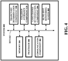
- FIG. 4 illustrates a block diagram of an example, non-limiting system 402 in accordance with one or more embodiments described herein.
- System 402 can be similar to system 302, and can comprise a memory 104, processor 106, trajectory determination component 108, collision avoidance component 110, bus 112, and/or lane change determination component 204, and/or communication component 304. Repetitive description of like elements and/or processes employed in respective embodiments is omitted for sake of brevity.
- System 402 can additionally comprise a blind spot monitoring sensor 404.
- a blind spot monitoring sensor 404 one or more of the memory 104, processor 106, trajectory determination component 108, collision avoidance component 110, bus 112, and/or lane change determination component 204, communication component 304, and/or blind spot monitoring sensor 404 can be communicatively or operably coupled to one another to perform one or more functions of the system 402.
- the blind spot monitoring sensor 404 can comprise a sensor of the system 402 (or of a vehicle comprising the system 402 and communicatively coupled to the system 402).
- the trajectory determination component 108 can determine a trajectory of a vehicle (e.g., an adjacent-lane traveling vehicle) based on an output received from the blind spot monitoring sensor 404.
- the blind spot monitoring sensor 404 can comprise one or more of a variety of sensors.
- the blind spot monitoring sensor 404 can comprise a group of sensors, or can comprise a singular sensor.
- the blind spot monitoring sensor 404 can comprise a camera (e.g., a rear-facing camera with respect to a vehicle comprising the system 402).
- the blind spot monitoring sensor 404 can comprise multiple cameras (e.g., a pair of cameras) to employ stereo vision for improved depth perception.
- the blind spot monitoring sensor 404 can comprise a radar sensor.
- the blind spot monitoring sensor 404 can comprise a lidar sensor, or another suitable sensor.
- one or more of the foregoing sensors can be utilized individually or collectively (e.g., sensor fusion).
- FIG. 5 illustrates a block diagram of an example, non-limiting system 502 in accordance with one or more embodiments described herein.
- System 502 can be similar to system 402, and can comprise a memory 104, processor 106, trajectory determination component 108, collision avoidance component 110, bus 112, and/or lane change determination component 204, communication component 304, and/or blind spot monitoring sensor 404. Repetitive description of like elements and/or processes employed in respective embodiments is omitted for sake of brevity.
- System 502 can additionally comprise an artificial intelligence component 504.
- one or more of the memory 104, processor 106, trajectory determination component 108, collision avoidance component 110, bus 112, and/or lane change determination component 204, communication component 304, blind spot monitoring sensor 404, and/or artificial intelligence component 504 can be communicatively or operably coupled to one another to perform one or more functions of the system 502.
- Artificial-intelligence or machine learning systems and techniques can be employed (e.g., using the artificial intelligence component 504) to facilitate learning user behavior, context-based scenarios, preferences, etc. in order to facilitate taking automated action with high degrees of confidence.
- Utility-based analysis can be utilized to factor benefit of taking an action against cost of taking an incorrect action.
- Probabilistic or statistical-based analyses can be employed in connection with the foregoing and/or the following.
- the artificial intelligence component 504 can utilize machine learning applied to past adjacent-lane traveling vehicle information representative of past trajectories of adjacent-lane traveling vehicles (e.g., from prior to experiencing the adjacent-lane traveling vehicle), to determine the trajectory of another vehicle (e.g., the adjacent-lane traveling vehicle).
- the artificial intelligence component 504 can generate a trajectory prediction model employable for the prediction of trajectories of vehicles herein (e.g., a vehicle comprising the system 502 or other surrounding vehicles). It is noted that such a trajectory prediction model can be continuously improved over time, based on comparing trajectory predictions (e.g., as predicted by the artificial intelligence component 504) and/or actual trajectories taken by respective vehicles.
- the collision avoidance component 110 can be employable to mitigate a collision based on such predictions made by the artificial intelligence component 504 and/or trajectory determination component 108.
- the artificial intelligence component 504 can be employable (e.g., by the trajectory determination component 108) in order to improve such trajectory determinations or to generate the model for which the trajectory determination component 108 bases such trajectory determinations/predictions.
- the artificial intelligence component 504 can learn optimal collision avoidance actions (e.g., based on comparisons of collision avoidance actions taken, such as by the collision avoidance component 110 and a rate of success of such collision avoidance actions).
- the artificial intelligence component 504 can generate a collision avoidance model employable for optimizing collision avoidance actions based on probabilities of success and/or a cost of not taking such an action or taking a different action.
- artificial intelligence component 504 can comprise and/or employ an artificial intelligence (AI) model and/or a machine learning (ML) model that can learn to perform the above or below described functions (e.g., via training using historical training data and/or feedback data).
- AI artificial intelligence
- ML machine learning
- artificial intelligence component 504 can comprise an AI and/or ML model that can be trained (e.g., via supervised and/or unsupervised techniques) to perform the above-described functions using historical training data comprising various context conditions.
- an AI and/or ML model can further learn (e.g., via supervised and/or unsupervised techniques) to perform the above-described functions using training data comprising feedback data, where such feedback data can be collected and/or stored (e.g., in memory 104) by artificial intelligence component 504.
- feedback data can comprise the various instructions described above/below that can be input, for instance, to a system 502, over time in response to observed/stored context-based information.
- artificial intelligence component 504 can perform such functions in the same manner and/or using the same resources as those of the trajectory determination component 108, collision avoidance component 110, bus 112, lane change determination component 204, communication component 304, and/or blind spot monitoring sensor 404.
- Artificial intelligence component 504 can initiate an operation based on a defined level of confidence determined using information (e.g., feedback data). For example, based on learning to perform such functions described above using the above defined feedback data, artificial intelligence component 504 can initiate an operation if it determines, based on such feedback data, a vehicle comprising the system 502 or a surround vehicle is/will take a specific trajectory or navigational operation. For instance, based on learning to perform such functions described above using the above defined feedback data, artificial intelligence component 504 can determine appropriate corresponding actions.
- information e.g., feedback data
- Artificial intelligence component 504 can initiate an operation based on a defined level of confidence determined using information (e.g., feedback data). For example, based on learning to perform such functions described above using the above defined feedback data, artificial intelligence component 504 can initiate an operation if it determines, based on such feedback data, a vehicle comprising the system 502 or a surround vehicle is/will take a specific trajectory or navigational operation. For instance, based on learning to perform such functions
- artificial intelligence component 504 can perform a utility-based analysis that factors cost of initiating the above-described operations versus benefit. In this embodiment, artificial intelligence component 504 can use one or more additional context conditions to determine whether any action should be taken.
- artificial intelligence component 504 can perform classifications, correlations, inferences, and/or expressions associated with principles of artificial intelligence.
- artificial intelligence component 504 can employ an automatic classification system and/or an automatic classification.
- artificial intelligence component 504 can employ a probabilistic and/or statistical-based analysis (e.g., factoring into the analysis utilities and costs) to learn and/or generate inferences.
- Artificial intelligence component 504 can employ any suitable machine-learning based techniques, statistical-based techniques and/or probabilistic-based techniques.
- artificial intelligence component 504 can employ expert systems, fuzzy logic, support vector machines (SVMs), Hidden Markov Models (HMMs), greedy search algorithms, rule-based systems, Bayesian models (e.g., Bayesian networks), neural networks, other non-linear training techniques, data fusion, utility-based analytical systems, systems employing Bayesian models, and/or the like.
- artificial intelligence component 504 can perform a set of machine learning computations.
- artificial intelligence component 504 can perform a set of clustering machine learning computations, a set of logistic regression machine learning computations, a set of decision tree machine learning computations, a set of random forest machine learning computations, a set of regression tree machine learning computations, a set of least square machine learning computations, a set of instance-based machine learning computations, a set of regression machine learning computations, a set of support vector regression machine learning computations, a set of k-means machine learning computations, a set of spectral clustering machine learning computations, a set of rule learning machine learning computations, a set of Bayesian machine learning computations, a set of deep Boltzmann machine computations, a set of deep belief network computations, and/or a set of different machine learning computations.
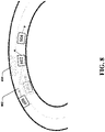
- vehicle 602 can represent a vehicle (e.g., comprising a system herein), vehicle 604 can represent a preceding vehicle, vehicle 606 can represent a succeeding vehicle, and vehicle 608 can represent an adjacent lane traveling vehicle.
- Coverage area 610 can represent a coverage area of a conventional blind spot monitoring system.
- vehicle 608 is not observable by the vehicle 602 or of a driver of the vehicle 602, because vehicle 608 is not within the coverage area 610 and is obstructed from view of a driver of the vehicle 602 by the vehicle 606.
- a lane change by vehicle 602 into the adjacent lane can lead to a potential collision between the vehicle 602 and the vehicle 608.
- the vehicle 602 comprises a system 102, system 202, system 302, system 402, or system 502.
- a sensor e.g., blind spot monitoring sensor 404
- the blind spot monitoring sensor 404 is therefore employable to track vehicle 608 and enable a system herein to determine/predict a current or future trajectory of the vehicle 608.
- intent of the vehicle 608 can be predicted (e.g., before a view of the vehicle 608 is obstructed by another vehicle such as the vehicle 606) so that an appropriate collision mitigation action can be enabled and facilitated.
- vehicle 608 can be engaging an in an overtaking maneuver of vehicle 606, vehicle 602, and or vehicle 604.
- vehicle 608 can be traveling faster than the vehicle 606 and/or vehicle 602.
- Prediction of the intent and/or trajectory of the vehicle 608 can enable a collision avoidance component 110 to initiate an appropriate collision avoidance action (e.g., if a lane change by vehicle 602 is unsafe and/or attempting to be undertaken) in order to mitigate a collision between the vehicle 602 and the vehicle 608.
- each of vehicles 602, 604, and 606 comprise a respective system 102, system 202, system 302, system 402, and/or system 502. It is noted that vehicles 602, 604, and 606 can be located in a defined geographic risk zone 906.
- the defined geographic risk zone 906 can be determined (e.g., by the artificial intelligence component 504) based on historical data (e.g., comprising an elevated rate of collision mitigation actions taken by one or more vehicles or an elevated rate of vehicle collision).
- an elevated rate of collision mitigation actions or collisions can be determined based on a comparison of said historical data to a collision mitigation threshold or a collision threshold.
- the artificial intelligence component 504 can learn to determine such thresholds. Further in this regard, the defined geographic risk zone 906 can be determined using machine learning applied to collision information representative of past collisions, or near-misses of other vehicles, to determine the defined geographic risk zone 906.
- vehicles 602, 604, and 606 can communicate via direct vehicle-to-vehicle communication (e.g., using respective communication components 304). It is noted that vehicles 602, 604, and 606 can each comprise respective blind spot monitoring sensors 404. In this regard, each of the vehicles 602, 604, and 606 can communicate with one another to share raw captured data (e.g., from the blind spot monitoring sensors 404), trajectory determinations or predictions of respective vehicles or other vehicles, collision mitigation actions undertaken, or other suitable information.
- such vehicle-to-vehicle communication can be initiated upon entering the defined geographic risk zone 906. In other embodiments, such vehicle-to-vehicle communication can be initiated upon entering a defined range of another vehicle capable of such vehicle-to-vehicle communication.
- vehicle 608 can additionally comprise a system 102, system 202, system 302, system 402, or system 502, and can directly communicate its own intent (or its own predicted intent) to other vehicles, such as vehicle 602, vehicle 604, and/or vehicle 606.
- vehicles 602, 604, and/or 606 can directly communicate their own respective intents or predicted intents for trajectories or navigational operations.
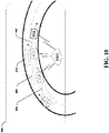
- FIG. 10 illustrates a scenario similar to that of FIG. 9 .
- vehicles 602, 604, and 606 can utilize cloud-based communication, in which vehicles 602, 604, and 606 communicate with one another via a network (e.g., a network 1002, such as a cellular network, using respective communication components 304).
- a network e.g., a network 1002, such as a cellular network, using respective communication components 304.
- FIG. 11 illustrates a flow chart of an example, non-limiting flowchart of a process 1100 for collision mitigation in accordance with one or more embodiments described herein.
- data can be received or accessed (e.g., from a blind spot monitoring sensor 404).
- a trajectory of a vehicle e.g., an adjacent lane traveling vehicle such as the vehicle 608 can be determined (e.g., by the trajectory determination component 108).
- a lane change can be safely executed (e.g., as determined by the collision avoidance component 110) (e.g., Y at 1106)
- the process can proceed to 1112, at which data relating to the safe lane change (e.g., vehicle speed, vehicle trajectory, distances between vehicles, location information, corresponding adjacent-lane traveling vehicle information, or other suitable information) is stored (e.g., for further analysis by an artificial intelligence component 504 such as for model generation and determination, prediction, and/or warning improvement).
- an alert signal associated with the collision can be generated (e.g., by the collision avoidance component 110).
- a collision avoidance action as described herein can be executed (e.g., by the collision avoidance component 110).
- data e.g., vehicle speed, vehicle trajectory, distances between vehicles, location information, corresponding adjacent-lane traveling vehicle information, or other suitable information
- an artificial intelligence component 504 such as for model generation and determination, prediction, and/or warning improvement.
- FIG. 12 illustrates a flow diagram of an example, non-limiting computer-implemented method 1200 in accordance with one or more embodiments described herein. Repetitive description of like elements and/or processes employed in respective embodiments is omitted for sake of brevity.
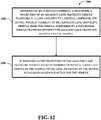
- computer-implemented method 1200 can comprise determining, by a device comprising a processor, a trajectory of an adjacent-lane traveling vehicle traveling in a lane adjacent to a vehicle comprising the device, wherein visibility of the adjacent-lane traveling vehicle, from the vehicle, is impaired by a succeeding vehicle traveling between the adjacent-lane traveling vehicle and the vehicle.
- the computer-implemented method 1200 can comprise in response to the trajectory of the adjacent-lane traveling vehicle being determined to prevent a safe lane change by the vehicle to the lane, initiating, by the device, a collision avoidance action for the vehicle.
- FIG. 13 illustrates a flow diagram of example, non-limiting non-transitory machine-readable medium, comprising executable instructions that, when executed by a processor, facilitate performance of operations 1300 in in accordance with one or more embodiments described herein. Repetitive description of like elements and/or processes employed in respective embodiments is omitted for sake of brevity.
- the operations 1300 can comprise determining a trajectory of an adjacent-lane traveling vehicle traveling in a lane adjacent to a vehicle, wherein visibility of the adjacent-lane traveling vehicle, from the vehicle, is impaired by a succeeding vehicle traveling between the adjacent-lane traveling vehicle and the vehicle.
- the operations 1300 can comprise in response to the trajectory of the adjacent-lane traveling vehicle being determined to prevent a safe lane change by the vehicle to the lane, initiating a collision avoidance action for the vehicle.
- Systems described herein can be coupled (e.g., communicatively, electrically, operatively, optically, etc.) to one or more local or remote (e.g., external) systems, sources, and/or devices (e.g., electronic control systems (ECU), classical and/or quantum computing devices, communication devices, etc.).
- local or remote systems e.g., external
- sources e.g., sources, and/or devices
- devices e.g., electronic control systems (ECU), classical and/or quantum computing devices, communication devices, etc.
- system 102 (or other systems, controllers, processors, etc.) can be coupled (e.g., communicatively, electrically, operatively, optically, etc.) to one or more local or remote (e.g., external) systems, sources, and/or devices using a data cable (e.g., High-Definition Multimedia Interface (HDMI), recommended standard (RS), Ethernet cable, etc.) and/or one or more wired networks described below.
- a data cable e.g., High-Definition Multimedia Interface (HDMI), recommended standard (RS), Ethernet cable, etc.
- system herein can be coupled (e.g., communicatively, electrically, operatively, optically, etc.) to one or more local or remote (e.g., external) systems, sources, and/or devices (e.g., electronic control units (ECU), classical and/or quantum computing devices, communication devices, etc.) via a network.
- a network can comprise one or more wired and/or wireless networks, including, but not limited to, a cellular network, a wide area network (WAN) (e.g., the Internet), and/or a local area network (LAN).
- WAN wide area network
- LAN local area network
- system 102 can communicate with one or more local or remote (e.g., external) systems, sources, and/or devices, for instance, computing devices using such a network, which can comprise virtually any desired wired or wireless technology, including but not limited to: powerline ethernet, wireless fidelity (Wi-Fi), BLUETOOTH ® , fiber optic communications, global system for mobile communications (GSM), universal mobile telecommunications system (UMTS), worldwide interoperability for microwave access (WiMAX), enhanced general packet radio service (enhanced GPRS), third generation partnership project (3GPP) long term evolution (LTE), third generation partnership project 2 (3GPP2) ultra-mobile broadband (UMB), high speed packet access (HSPA), Zigbee and other 802.XX wireless technologies and/or legacy telecommunication technologies, Session Initiation Protocol (SIP), ZIGBEE ® , RF4CE protocol, WirelessHART protocol, 6LoWPAN (IPv6 over Low power Wireless Area Networks), Z-Wave, an IP fidelity
- system 102 can thus include hardware (e.g., a central processing unit (CPU), a transceiver, a decoder, an antenna (e.g., a ultra-wideband (UWB) antenna, a BLUETOOTH ® low energy (BLE) antenna, etc.), quantum hardware, a quantum processor, etc.), software (e.g., a set of threads, a set of processes, software in execution, quantum pulse schedule, quantum circuit, quantum gates, etc.), or a combination of hardware and software that facilitates communicating information between a system herein and remote (e.g., external) systems, sources, and/or devices (e.g., computing and/or communication devices such as, for instance, a smart phone, a smart watch, wireless earbuds, etc.).
- hardware e.g., a central processing unit (CPU), a transceiver, a decoder, an antenna (e.g., a ultra-wideband (UWB) antenna, a BLU
- System herein can comprise one or more computer and/or machine readable, writable, and/or executable components and/or instructions that, when executed by processor (e.g., a processor 106 which can comprise a classical processor, a quantum processor, etc.), can facilitate performance of operations defined by such component(s) and/or instruction(s).
- processor e.g., a processor 106 which can comprise a classical processor, a quantum processor, etc.
- any component associated with a system herein, as described herein with or without reference to the various figures of the subject disclosure can comprise one or more computer and/or machine readable, writable, and/or executable components and/or instructions that, when executed by a processor, can facilitate performance of operations defined by such component(s) and/or instruction(s).
- system herein and/or any components associated therewith as disclosed herein can employ a processor (e.g., processor 106) to execute such computer and/or machine readable, writable, and/or executable component(s) and/or instruction(s) to facilitate performance of one or more operations described herein with reference to system herein and/or any such components associated therewith.
- processor 106 e.g., processor 106
- Systems herein can comprise any type of system, device, machine, apparatus, component, and/or instrument that comprises a processor and/or that can communicate with one or more local or remote electronic systems and/or one or more local or remote devices via a wired and/or wireless network. All such embodiments are envisioned.
- a system can comprise a computing device, a general-purpose computer, a special-purpose computer, an onboard computing device, a communication device, an onboard communication device, a server device, a quantum computing device (e.g., a quantum computer), a tablet computing device, a handheld device, a server class computing machine and/or database, a laptop computer, a notebook computer, a desktop computer, a cell phone, a smart phone, a consumer appliance and/or instrumentation, an industrial and/or commercial device, a digital assistant, a multimedia Internet enabled phone, a multimedia players, and/or another type of device.
- a computing device e.g., a system 502 or any other system or device described herein
- a computing device e.g., a system 502 or any other system or device described herein
- a computing device e.g., a system 502 or any other system or device described herein
- a computing device e.g., a system 502 or any other system or device described
- FIG. 14 and the following discussion are intended to provide a brief, general description of a suitable computing environment 1400 in which the various embodiments of the embodiment described herein can be implemented. While the embodiments have been described above in the general context of computer-executable instructions that can run on one or more computers, those skilled in the art will recognize that the embodiments can be also implemented in combination with other program modules and/or as a combination of hardware and software.
- program modules include routines, programs, components, data structures, etc., that perform particular tasks or implement particular abstract data types.
- inventive methods can be practiced with other computer system configurations, including single-processor or multiprocessor computer systems, minicomputers, mainframe computers, Internet of Things (IoT) devices, distributed computing systems, as well as personal computers, hand-held computing devices, microprocessor-based or programmable consumer electronics, and the like, each of which can be operatively coupled to one or more associated devices.
- IoT Internet of Things
- the illustrated embodiments of the embodiments herein can be also practiced in distributed computing environments where certain tasks are performed by remote processing devices that are linked through a communications network.
- program modules can be located in both local and remote memory storage devices.
- Computer-readable storage media or machine-readable storage media can be any available storage media that can be accessed by the computer and includes both volatile and nonvolatile media, removable and non-removable media.
- Computer-readable storage media or machine-readable storage media can be implemented in connection with any method or technology for storage of information such as computer-readable or machine-readable instructions, program modules, structured data, or unstructured data.
- Computer-readable storage media can include, but are not limited to, random access memory (RAM), read only memory (ROM), electrically erasable programmable read only memory (EEPROM), flash memory or other memory technology, compact disk read only memory (CD-ROM), digital versatile disk (DVD), Blu-ray disc (BD) or other optical disk storage, magnetic cassettes, magnetic tape, magnetic disk storage or other magnetic storage devices, solid state drives or other solid state storage devices, or other tangible and/or non-transitory media which can be used to store desired information.
- RAM random access memory
- ROM read only memory
- EEPROM electrically erasable programmable read only memory
- flash memory or other memory technology
- CD-ROM compact disk read only memory
- DVD digital versatile disk
- Blu-ray disc (BD) or other optical disk storage magnetic cassettes, magnetic tape, magnetic disk storage or other magnetic storage devices, solid state drives or other solid state storage devices, or other tangible and/or non-transitory media which can be used to store desired information.
- tangible or “non-transitory” herein as applied to storage, memory, or computer-readable media, are to be understood to exclude only propagating transitory signals per se as modifiers and do not relinquish rights to all standard storage, memory or computer-readable media that are not only propagating transitory signals per se.
- Computer-readable storage media can be accessed by one or more local or remote computing devices, e.g., via access requests, queries, or other data retrieval protocols, for a variety of operations with respect to the information stored by the medium.
- Communications media typically embody computer-readable instructions, data structures, program modules or other structured or unstructured data in a data signal such as a modulated data signal, e.g., a carrier wave or other transport mechanism, and includes any information delivery or transport media.
- modulated data signal or signals refers to a signal that has one or more of its characteristics set or changed in such a manner as to encode information in one or more signals.
- communication media include wired media, such as a wired network or direct-wired connection, and wireless media such as acoustic, RF, infrared, and other wireless media.
- the example environment 1400 for implementing various embodiments of the aspects described herein includes a computer 1402, the computer 1402 including a processing unit 1404, a system memory 1406 and a system bus 1408.
- the system bus 1408 couples system components including, but not limited to, the system memory 1406 to the processing unit 1404.
- the processing unit 1404 can be any of various commercially available processors. Dual microprocessors and other multi-processor architectures can also be employed as the processing unit 1404.
- the system bus 1408 can be any of several types of bus structure that can further interconnect to a memory bus (with or without a memory controller), a peripheral bus, and a local bus using any of a variety of commercially available bus architectures.
- the system memory 1406 includes ROM 1410 and RAM 1412.
- a basic input/output system (BIOS) can be stored in a non-volatile memory such as ROM, erasable programmable read only memory (EPROM), EEPROM, which BIOS contains the basic routines that help to transfer information between elements within the computer 1402, such as during startup.
- the RAM 1412 can also include a high-speed RAM such as static RAM for caching data.
- the computer 1402 further includes an internal hard disk drive (HDD) 1414 (e.g., EIDE, SATA), one or more external storage devices 1416 (e.g., a magnetic floppy disk drive (FDD) 1416, a memory stick or flash drive reader, a memory card reader, etc.) and an optical disk drive 1420 (e.g., which can read or write from a CD-ROM disc, a DVD, a BD, etc.).
- HDD hard disk drive
- FDD magnetic floppy disk drive
- FDD magnetic floppy disk drive
- memory stick or flash drive reader e.g., a memory stick or flash drive reader
- a memory card reader e.g., a memory card reader
- optical disk drive 1420 e.g., which can read or write from a CD-ROM disc, a DVD, a BD, etc.
- SSD solid-state drive
- the HDD 1414, external storage device(s) 1416 and optical disk drive 1420 can be connected to the system bus 1408 by an HDD interface 1424, an external storage interface 1426 and an optical drive interface 1428, respectively.
- the interface 1424 for external drive implementations can include at least one or both of Universal Serial Bus (USB) and Institute of Electrical and Electronics Engineers (IEEE) 1394 interface technologies. Other external drive connection technologies are within contemplation of the embodiments described herein.
- the drives and their associated computer-readable storage media provide nonvolatile storage of data, data structures, computer-executable instructions, and so forth.
- the drives and storage media accommodate the storage of any data in a suitable digital format.
- computer-readable storage media refers to respective types of storage devices, it should be appreciated by those skilled in the art that other types of storage media which are readable by a computer, whether presently existing or developed in the future, could also be used in the example operating environment, and further, that any such storage media can contain computer-executable instructions for performing the methods described herein.
- a number of program modules can be stored in the drives and RAM 1412, including an operating system 1430, one or more application programs 1432, other program modules 1434 and program data 1436. All or portions of the operating system, applications, modules, and/or data can also be cached in the RAM 1412.
- the systems and methods described herein can be implemented utilizing various commercially available operating systems or combinations of operating systems.
- Computer 1402 can optionally comprise emulation technologies.
- a hypervisor (not shown) or other intermediary can emulate a hardware environment for operating system 1430, and the emulated hardware can optionally be different from the hardware illustrated in FIG. 14 .
- operating system 1430 can comprise one virtual machine (VM) of multiple VMs hosted at computer 1402.
- VM virtual machine
- operating system 1430 can provide runtime environments, such as the Java runtime environment or the .NET framework, for applications 1432. Runtime environments are consistent execution environments that allow applications 1432 to run on any operating system that includes the runtime environment.
- operating system 1430 can support containers, and applications 1432 can be in the form of containers, which are lightweight, standalone, executable packages of software that include, e.g., code, runtime, system tools, system libraries and settings for an application.
- computer 1402 can be enable with a security module, such as a trusted processing module (TPM).
- TPM trusted processing module
- boot components hash next in time boot components, and wait for a match of results to secured values, before loading a next boot component.
- This process can take place at any layer in the code execution stack of computer 1402, e.g., applied at the application execution level or at the operating system (OS) kernel level, thereby enabling security at any level of code execution.
- OS operating system
- a user can enter commands and information into the computer 1402 through one or more wired/wireless input devices, e.g., a keyboard 1438, a touch screen 1440, and a pointing device, such as a mouse 1442.
- Other input devices can include a microphone, an infrared (IR) remote control, a radio frequency (RF) remote control, or other remote control, a joystick, a virtual reality controller and/or virtual reality headset, a game pad, a stylus pen, an image input device, e.g., camera(s), a gesture sensor input device, a vision movement sensor input device, an emotion or facial detection device, a biometric input device, e.g., fingerprint or iris scanner, or the like.
- IR infrared
- RF radio frequency
- input devices are often connected to the processing unit 1404 through an input device interface 1444 that can be coupled to the system bus 1408, but can be connected by other interfaces, such as a parallel port, an IEEE 1394 serial port, a game port, a USB port, an IR interface, a BLUETOOTH ® interface, etc.
- a monitor 1446 or other type of display device can be also connected to the system bus 1408 via an interface, such as a video adapter 1448.
- a computer typically includes other peripheral output devices (not shown), such as speakers, printers, etc.
- the computer 1402 can operate in a networked environment using logical connections via wired and/or wireless communications to one or more remote computers, such as a remote computer(s) 1450.
- the remote computer(s) 1450 can be a workstation, a server computer, a router, a personal computer, portable computer, microprocessor-based entertainment appliance, a peer device or other common network node, and typically includes many or all of the elements described relative to the computer 1402, although, for purposes of brevity, only a memory/storage device 1452 is illustrated.
- the logical connections depicted include wired/wireless connectivity to a local area network (LAN) 1454 and/or larger networks, e.g., a wide area network (WAN) 1456.
- LAN and WAN networking environments are commonplace in offices and companies, and facilitate enterprise-wide computer networks, such as intranets, all of which can connect to a global communications network, e.g., the Internet.
- the computer 1402 can be connected to the local network 1454 through a wired and/or wireless communication network interface or adapter 1458.
- the adapter 1458 can facilitate wired or wireless communication to the LAN 1454, which can also include a wireless access point (AP) disposed thereon for communicating with the adapter 1458 in a wireless mode.
- AP wireless access point
- the computer 1402 can include a modem 1460 or can be connected to a communications server on the WAN 1456 via other means for establishing communications over the WAN 1456, such as by way of the Internet.
- the modem 1460 which can be internal or external and a wired or wireless device, can be connected to the system bus 1408 via the input device interface 1444.
- program modules depicted relative to the computer 1402 or portions thereof can be stored in the remote memory/storage device 1452. It will be appreciated that the network connections shown are example and other means of establishing a communications link between the computers can be used.
- the computer 1402 can access cloud storage systems or other network-based storage systems in addition to, or in place of, external storage devices 1416 as described above.
- a connection between the computer 1402 and a cloud storage system can be established over a LAN 1454 or WAN 1456 e.g., by the adapter 1458 or modem 1460, respectively.
- the external storage interface 1426 can, with the aid of the adapter 1458 and/or modem 1460, manage storage provided by the cloud storage system as it would other types of external storage.
- the external storage interface 1426 can be configured to provide access to cloud storage sources as if those sources were physically connected to the computer 1402.
- the computer 1402 can be operable to communicate with any wireless devices or entities operatively disposed in wireless communication, e.g., a printer, scanner, desktop and/or portable computer, portable data assistant, communications satellite, any piece of equipment or location associated with a wirelessly detectable tag (e.g., a kiosk, news stand, store shelf, etc.), and telephone.
- any wireless devices or entities operatively disposed in wireless communication e.g., a printer, scanner, desktop and/or portable computer, portable data assistant, communications satellite, any piece of equipment or location associated with a wirelessly detectable tag (e.g., a kiosk, news stand, store shelf, etc.), and telephone.
- This can include Wireless Fidelity (Wi-Fi) and BLUETOOTH ® wireless technologies.
- the communication can be a predefined structure as with a conventional network or simply an ad hoc communication between at least two devices.
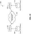
- the system 1500 includes one or more client(s) 1502, (e.g., computers, smart phones, tablets, cameras, PDA's).
- the client(s) 1502 can be hardware and/or software (e.g., threads, processes, computing devices).
- the client(s) 1502 can house cookie(s) and/or associated contextual information by employing the specification, for example.
- the system 1500 also includes one or more server(s) 1504.
- the server(s) 1504 can also be hardware or hardware in combination with software (e.g., threads, processes, computing devices).
- the servers 1504 can house threads to perform transformations of media items by employing aspects of this disclosure, for example.
- One possible communication between a client 1502 and a server 1504 can be in the form of a data packet adapted to be transmitted between two or more computer processes wherein data packets can include coded analyzed headspaces and/or input.
- the data packet can include a cookie and/or associated contextual information, for example.
- the system 1500 includes a communication framework 1506 (e.g., a global communication network such as the Internet) that can be employed to facilitate communications between the client(s) 1502 and the server(s) 1504.
- a communication framework 1506 e.g., a global communication network such as the Internet
- Communications can be facilitated via a wired (including optical fiber) and/or wireless technology.
- the client(s) 1502 are operatively connected to one or more client data store(s) 1508 that can be employed to store information local to the client(s) 1502 (e.g ., cookie(s) and/or associated contextual information).
- the server(s) 1504 are operatively connected to one or more server data store(s) 1510 that can be employed to store information local to the servers 1504.
- a client 1502 can transfer an encoded file, (e.g., encoded media item), to server 1504.
- Server 1504 can store the file, decode the file, or transmit the file to another client 1502. It is to be appreciated, that a client 1502 can also transfer uncompressed file to a server 1504 and server 1504 can compress the file and/or transform the file in accordance with this disclosure.
- server 1504 can encode information and transmit the information via communication framework 1506 to one or more clients 1502.
- program modules can be located in both local and remote memory storage devices.
- the terms (including a reference to a "means") used to describe such components are intended to also include, unless otherwise indicated, any structure(s) which performs the specified function of the described component (e.g., a functional equivalent), even if not structurally equivalent to the disclosed structure.
- any structure(s) which performs the specified function of the described component e.g., a functional equivalent
- a particular feature of the disclosed subject matter may have been disclosed with respect to only one of several implementations, such feature can be combined with one or more other features of the other implementations as may be desired and advantageous for any given or particular application.
- exemplary and/or “demonstrative” as used herein are intended to mean serving as an example, instance, or illustration. For the avoidance of doubt, the subject matter disclosed herein is not limited by such examples.
- any aspect or design described herein as “exemplary” and/or “demonstrative” is not necessarily to be construed as preferred or advantageous over other aspects or designs, nor is it meant to preclude equivalent structures and techniques known to one skilled in the art.
- the terms “includes,” “has,” “contains,” and other similar words are used in either the detailed description or the claims, such terms are intended to be inclusive - in a manner similar to the term “comprising” as an open transition word - without precluding any additional or other elements.
- set as employed herein excludes the empty set, i.e., the set with no elements therein.
- a “set” in the subject disclosure includes one or more elements or entities.
- group as utilized herein refers to a collection of one or more entities.
Applications Claiming Priority (1)
| Application Number | Priority Date | Filing Date | Title |
|---|---|---|---|
| US17/363,144 US11887481B2 (en) | 2021-06-30 | 2021-06-30 | Rear view collision warning indication and mitigation |
Publications (1)
| Publication Number | Publication Date |
|---|---|
| EP4113480A1 true EP4113480A1 (fr) | 2023-01-04 |
Family
ID=82403568
Family Applications (1)
| Application Number | Title | Priority Date | Filing Date |
|---|---|---|---|
| EP22181558.2A Pending EP4113480A1 (fr) | 2021-06-30 | 2022-06-28 | Indication et atténuation d'avertissement de collision de vue arrière |
Country Status (3)
| Country | Link |
|---|---|
| US (1) | US11887481B2 (fr) |
| EP (1) | EP4113480A1 (fr) |
| CN (1) | CN115556742A (fr) |
Citations (2)
| Publication number | Priority date | Publication date | Assignee | Title |
|---|---|---|---|---|
| US20180281804A1 (en) * | 2017-03-31 | 2018-10-04 | Ford Global Technologies, Llc | Virtual steerable path |
| US20190347939A1 (en) * | 2018-05-14 | 2019-11-14 | Toyota Jidosha Kabushiki Kaisha | Lane change timing indicator |
Family Cites Families (32)
| Publication number | Priority date | Publication date | Assignee | Title |
|---|---|---|---|---|
| DE2156001B2 (de) * | 1971-11-11 | 1975-10-16 | Daimler-Benz Ag, 7000 Stuttgart | Abstandswarnvorrichtung für Fahrzeuge |
| US8041483B2 (en) * | 1994-05-23 | 2011-10-18 | Automotive Technologies International, Inc. | Exterior airbag deployment techniques |
| JP4298577B2 (ja) * | 2004-05-06 | 2009-07-22 | 三菱電機株式会社 | 車両用警報装置 |
| US8585221B2 (en) * | 2010-11-03 | 2013-11-19 | Dann M Allen | Bi-directional blind sight illumination and deflector device |
| DE102011077384A1 (de) * | 2011-06-10 | 2012-12-13 | Robert Bosch Gmbh | Vorrichtung und Verfahren zum Warnen eines Fahrers eines Kraftfahrzeugs |
| JP5760884B2 (ja) * | 2011-09-09 | 2015-08-12 | 株式会社デンソー | 車両の旋回予測装置 |
| DE102012215014A1 (de) * | 2012-08-23 | 2014-02-27 | Robert Bosch Gmbh | Verfahren zur Überwachung eines toten Winkels und Fahrassistenzsystem |
| DE102012111318A1 (de) * | 2012-11-23 | 2014-05-28 | Hella Kgaa Hueck & Co. | Fahrassistenzsystem eines Fahrzeugs |
| AT514754B1 (de) * | 2013-09-05 | 2018-06-15 | Avl List Gmbh | Verfahren und Vorrichtung zur Optimierung von Fahrassistenzsystemen |
| DE102013217860A1 (de) * | 2013-09-06 | 2015-03-12 | Robert Bosch Gmbh | Verfahren und Vorrichtung zum Bestimmen eines Fahrbahnverlaufs einer Fahrbahn eines Fahrzeugs |
| KR102158745B1 (ko) * | 2014-03-18 | 2020-09-22 | 한국전자통신연구원 | 곡선 도로에서 주변 장애물 감지 보정 장치 및 그 동작 방법 |
| US9656606B1 (en) * | 2014-05-30 | 2017-05-23 | State Farm Mutual Automobile Insurance Company | Systems and methods for alerting a driver to vehicle collision risks |
| US9153133B1 (en) * | 2014-07-18 | 2015-10-06 | John D. Baker | Motorcycle blind spot detector |
| US10173695B2 (en) * | 2014-11-24 | 2019-01-08 | Here Global B.V. | Method and apparatus for providing notifications based on ranking of road links |
| JP6536064B2 (ja) * | 2015-02-10 | 2019-07-03 | 株式会社デンソー | 走行軌跡選定装置、走行軌跡選定方法 |
| JP6663822B2 (ja) * | 2016-08-08 | 2020-03-13 | 日立オートモティブシステムズ株式会社 | 自動運転装置 |
| JP6575492B2 (ja) * | 2016-11-29 | 2019-09-18 | トヨタ自動車株式会社 | 自動運転システム |
| KR102304709B1 (ko) * | 2017-03-03 | 2021-09-23 | 현대자동차주식회사 | V2x 통신 메시지에 대하여 적응적 보안 레벨을 적용하는 방법 및 장치 |
| US11210744B2 (en) * | 2017-08-16 | 2021-12-28 | Mobileye Vision Technologies Ltd. | Navigation based on liability constraints |
| US20200086789A1 (en) * | 2018-09-13 | 2020-03-19 | Valeo Comfort And Driving Assistance | Mixed reality left turn assistance to promote traffic efficiency and enhanced safety |
| US10839694B2 (en) * | 2018-10-18 | 2020-11-17 | Cartica Ai Ltd | Blind spot alert |
| US10347132B1 (en) * | 2018-10-30 | 2019-07-09 | GM Global Technology Operations LLC | Adjacent pedestrian collision mitigation |
| DE102018218835A1 (de) * | 2018-11-05 | 2020-05-07 | Hyundai Motor Company | Verfahren zur zumindest teilweisen Entblockung eines Sichtfeldes eines Kraftfahrzeugs, insbesondere während Fahrspurwechseln |
| EP3876215A4 (fr) * | 2018-12-20 | 2022-07-13 | OMRON Corporation | Dispositif de détection, système de corps mobile, et procédé de détection |
| WO2020170678A1 (fr) * | 2019-02-18 | 2020-08-27 | 株式会社小糸製作所 | Système de détection de véhicule et véhicule |
| US11235805B2 (en) * | 2019-02-28 | 2022-02-01 | International Business Machines Corporation | Adaptive vehicle-proximity guidance |
| US11718324B2 (en) * | 2019-04-11 | 2023-08-08 | Isee, Inc. | Instance segmentation imaging system |
| US11237562B2 (en) * | 2019-09-19 | 2022-02-01 | Caterpillar Inc. | System and method for avoiding contact between autonomous and manned vehicles caused by loss of traction |
| KR20210073313A (ko) * | 2019-12-10 | 2021-06-18 | 팅크웨어(주) | 주행 관련 안내 서비스를 제공하는 차량용 단말 장치, 서비스 제공 서버, 방법, 컴퓨터 프로그램 및 컴퓨터 판독 가능한 기록 매체 |
| KR20220033086A (ko) * | 2020-09-08 | 2022-03-16 | 현대자동차주식회사 | 군집주행 제어 장치 및 방법 |
| WO2022251880A1 (fr) * | 2021-05-28 | 2022-12-01 | Tusimple, Inc. | Systèmes et procédés de fonctionnement d'un véhicule autonome |
| US20220415179A1 (en) * | 2021-06-23 | 2022-12-29 | Qualcomm Incorporated | Sub-platoons within vehicle-to-everything technology |
-
2021
- 2021-06-30 US US17/363,144 patent/US11887481B2/en active Active
-
2022
- 2022-06-28 EP EP22181558.2A patent/EP4113480A1/fr active Pending
- 2022-06-29 CN CN202210757075.9A patent/CN115556742A/zh active Pending
Patent Citations (2)
| Publication number | Priority date | Publication date | Assignee | Title |
|---|---|---|---|---|
| US20180281804A1 (en) * | 2017-03-31 | 2018-10-04 | Ford Global Technologies, Llc | Virtual steerable path |
| US20190347939A1 (en) * | 2018-05-14 | 2019-11-14 | Toyota Jidosha Kabushiki Kaisha | Lane change timing indicator |
Also Published As
| Publication number | Publication date |
|---|---|
| US20230005373A1 (en) | 2023-01-05 |
| CN115556742A (zh) | 2023-01-03 |
| US11887481B2 (en) | 2024-01-30 |
Similar Documents
| Publication | Publication Date | Title |
|---|---|---|
| KR102304709B1 (ko) | V2x 통신 메시지에 대하여 적응적 보안 레벨을 적용하는 방법 및 장치 | |
| US10990096B2 (en) | Reinforcement learning on autonomous vehicles | |
| US10592785B2 (en) | Integrated system for detection of driver condition | |
| EP4075407A1 (fr) | Procédé de prédiction de trajectoire et dispositif associé | |
| US11644835B2 (en) | Game-theoretic planning for risk-aware interactive agents | |
| US20220410939A1 (en) | Collision detection method, electronic device, and medium | |
| WO2019006743A1 (fr) | Procédé et dispositif de contrôle de trajet de véhicule | |
| US11150656B2 (en) | Autonomous vehicle decision making | |
| EP3756372B1 (fr) | Fourniture de données de capteur sécurisées à des machines automatisées | |
| EP4047566A1 (fr) | Prévention des collisions latérales à basse vitesse avec des objets immobiles | |
| US11887481B2 (en) | Rear view collision warning indication and mitigation | |
| US20220126818A1 (en) | Systems and methods for identifying high-risk driving situations from driving data | |
| EP4116110A1 (fr) | Système de surveillance de pneu en temps réel | |
| EP4190672A1 (fr) | Compensation de non-uniformité de direction de véhicule | |
| US20210039660A1 (en) | Anomaly Detector For Vehicle Control Signals | |
| KR102352360B1 (ko) | 운전자의 시선에 기반한 장애물 후보들에 대한 분석 우선순위를 이용하여 장애물을 분석하는 방법 및 시스템 | |
| Lamouik et al. | Model predictive control for full autonomous vehicle overtaking | |
| US10802483B2 (en) | Emergency public deactivation of autonomous vehicles | |
| US20230161623A1 (en) | Vehicle as a distributed computing resource | |
| US20240140264A1 (en) | Automated vehicle battery health optimization | |
| US20220407892A1 (en) | Augmented reality security | |
| US11627252B2 (en) | Configuration of optical sensor devices in vehicles based on thermal data | |
| EP4105807A1 (fr) | Anonymisation dynamique pour les abonnements automobiles | |
| EP4293318A1 (fr) | Localisation pour mouvement autonome à l'aide de capteurs de véhicule | |
| US20220222600A1 (en) | User authentication and personalization without user credentials |
Legal Events
| Date | Code | Title | Description |
|---|---|---|---|
| PUAI | Public reference made under article 153(3) epc to a published international application that has entered the european phase |
Free format text: ORIGINAL CODE: 0009012 |
|
| STAA | Information on the status of an ep patent application or granted ep patent |
Free format text: STATUS: THE APPLICATION HAS BEEN PUBLISHED |
|
| AK | Designated contracting states |
Kind code of ref document: A1 Designated state(s): AL AT BE BG CH CY CZ DE DK EE ES FI FR GB GR HR HU IE IS IT LI LT LU LV MC MK MT NL NO PL PT RO RS SE SI SK SM TR |
|
| STAA | Information on the status of an ep patent application or granted ep patent |
Free format text: STATUS: REQUEST FOR EXAMINATION WAS MADE |
|
| 17P | Request for examination filed |
Effective date: 20230704 |
|
| RBV | Designated contracting states (corrected) |
Designated state(s): AL AT BE BG CH CY CZ DE DK EE ES FI FR GB GR HR HU IE IS IT LI LT LU LV MC MK MT NL NO PL PT RO RS SE SI SK SM TR |