EP4113221A1 - Armbanduhr, die ein zifferblatt mit einem festen teil und einem beweglichen teil umfasst - Google Patents
Armbanduhr, die ein zifferblatt mit einem festen teil und einem beweglichen teil umfasst Download PDFInfo
- Publication number
- EP4113221A1 EP4113221A1 EP21182574.0A EP21182574A EP4113221A1 EP 4113221 A1 EP4113221 A1 EP 4113221A1 EP 21182574 A EP21182574 A EP 21182574A EP 4113221 A1 EP4113221 A1 EP 4113221A1
- Authority
- EP
- European Patent Office
- Prior art keywords
- rotation
- zones
- crown
- control member
- watch according
- Prior art date
- Legal status (The legal status is an assumption and is not a legal conclusion. Google has not performed a legal analysis and makes no representation as to the accuracy of the status listed.)
- Pending
Links
Images
Classifications
-
- G—PHYSICS
- G04—HOROLOGY
- G04B—MECHANICALLY-DRIVEN CLOCKS OR WATCHES; MECHANICAL PARTS OF CLOCKS OR WATCHES IN GENERAL; TIME PIECES USING THE POSITION OF THE SUN, MOON OR STARS
- G04B47/00—Time-pieces combined with other articles which do not interfere with the running or the time-keeping of the time-piece
- G04B47/04—Time-pieces combined with other articles which do not interfere with the running or the time-keeping of the time-piece with attached ornaments or amusement apparatus
- G04B47/044—Movable decorations and parts thereof
-
- G—PHYSICS
- G04—HOROLOGY
- G04B—MECHANICALLY-DRIVEN CLOCKS OR WATCHES; MECHANICAL PARTS OF CLOCKS OR WATCHES IN GENERAL; TIME PIECES USING THE POSITION OF THE SUN, MOON OR STARS
- G04B19/00—Indicating the time by visual means
- G04B19/06—Dials
- G04B19/065—Dials with several parts
-
- G—PHYSICS
- G04—HOROLOGY
- G04B—MECHANICALLY-DRIVEN CLOCKS OR WATCHES; MECHANICAL PARTS OF CLOCKS OR WATCHES IN GENERAL; TIME PIECES USING THE POSITION OF THE SUN, MOON OR STARS
- G04B19/00—Indicating the time by visual means
- G04B19/06—Dials
- G04B19/10—Ornamental shape of the graduations or the surface of the dial; Attachment of the graduations to the dial
- G04B19/103—Ornamental shape of the graduations or the surface of the dial; Attachment of the graduations to the dial attached or inlaid numbers
-
- G—PHYSICS
- G04—HOROLOGY
- G04B—MECHANICALLY-DRIVEN CLOCKS OR WATCHES; MECHANICAL PARTS OF CLOCKS OR WATCHES IN GENERAL; TIME PIECES USING THE POSITION OF THE SUN, MOON OR STARS
- G04B19/00—Indicating the time by visual means
- G04B19/06—Dials
- G04B19/16—Shiftable dials, e.g. indicating alternately from 1 to 12 and from 13 to 24
-
- G—PHYSICS
- G04—HOROLOGY
- G04B—MECHANICALLY-DRIVEN CLOCKS OR WATCHES; MECHANICAL PARTS OF CLOCKS OR WATCHES IN GENERAL; TIME PIECES USING THE POSITION OF THE SUN, MOON OR STARS
- G04B45/00—Time pieces of which the indicating means or cases provoke special effects, e.g. aesthetic effects
- G04B45/003—Inscriptions and pictures moved by hand
Definitions
- the invention relates to the field of watchmaking, and in particular a watch comprising trim parts.
- the invention relates to a watch comprising a dial comprising a fixed part and a mobile part.
- timepieces in particular watches, which comprise movable elements on their dial for decorative use, for example kinematically connected to a watch movement which said timepieces comprise.
- the watch movement is adapted to move the moving elements according to the current time in order to generate a decor that changes over time.
- the invention solves the aforementioned drawbacks by proposing a watch whose appearance can be modified according to the wishes of the user.
- the present invention relates to a watch comprising a dial comprising a fixed part superimposed on a movable part in rotation comprising a surface on which are arranged areas of visual appearance different from each other.
- the fixed part comprises at least one through-opening opening onto at least one of the zones, the movable part being kinematically connected to a control member so as to be driven in rotation by actuation of said control member and being configured so that when it is driven in rotation, the areas of different visual aspect appear successively through the opening.
- the user can thus, on the one hand, modify the appearance of the dial of the watch by choosing the orientation of the mobile part so that the openings reveal areas with the desired visual aspects, and on the other hand obtain a attractive visual effect and an interactive decor during the rotation of the mobile part.
- the invention may also include one or more of the following characteristics, taken separately or in all technically possible combinations.
- the zones having the same visual appearance have an identical shape and dimensions
- the fixed part comprising at least two openings separated from each other by a bridge of material.
- Said openings and said bridge of material each substantially have a shape and dimensions corresponding to those of a zone, and are distributed so that each of the openings can reveal only one zone.
- the zones are arranged in the form of circular sectors adjacent to each other so that two successive circular sectors have a different visual appearance.
- two successive zones have the same visual appearance, a bridge of material having a shape and dimensions corresponding to those of the pair formed by said two successive zones.
- the movable part comprises a circular crown provided with a central orifice comprising internal toothing in meshing relationship with a toothed wheel adapted to be driven in rotation by the control member.
- the movable part comprises a circular crown provided with a central orifice, and comprises a disk arranged in the central orifice of the circular crown.
- the disc and the circular crown are concentric, kinematically connected to the control member and each comprise areas of different visual appearance from each other.
- the mobile part is kinematically connected to the control member so that the transmission ratios are such that the rotation of the mobile part is able to produce motion blurring of the areas visible through the openings. .
- control member is formed by a crown stem connected to a crown.
- the transmission ratios are chosen so that when the crown is pivoted by one revolution, the movable part is rotated by at least one revolution.
- the disk and the circular crown are meshed alternately by a sliding pinion, depending on the direction of rotation of the crown.
- the watch comprises a system for maintaining the movable part in position allowing it to be indexed according to at least one predefined position.
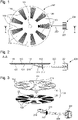
- the present invention relates to a watch comprising a dial 100 and a control member 200 as represented in isolation on the figures 1 to 3 .
- the watch comprises, in a manner known per se, a case composed of a middle part, a bezel and a back, said case forming an internal volume in which is housed a horological movement intended to rotate the hour hands, the minutes, and possibly seconds.
- a case composed of a middle part, a bezel and a back said case forming an internal volume in which is housed a horological movement intended to rotate the hour hands, the minutes, and possibly seconds.
- the aforementioned constituent elements of the watch are not shown in the figures because they are known as such to those skilled in the art and do not pertain as such to the present invention.
- the dial 100 is arranged so as to be interposed between a crystal and the watch movement, in a manner known to those skilled in the art.
- the dial 100 comprises a fixed part 110 integral with the middle part, the bezel or the watch movement, and superimposed on a mobile part 120 in rotation connected kinematically to the control member 200, as shown by the figures 1 to 3 , so as to be driven in rotation by the actuation of said control member 200 by a user.
- the fixed 110 and mobile 120 parts are in the form of flat thin parts and have central orifices 111 and 121 concentric, through which barrels of the needles are provided to be engaged.
- the mobile part 120 is capable of pivoting about an axis of rotation orthogonal to a plane defined by the fixed part 110.
- the axis of rotation of the movable part 120 is intended to coincide with the axis of rotation of the needles.
- the movable part 120 is, in the preferred embodiment shown in the figures, made in the form of a circular crown and comprises a surface on which are arranged areas 122 and 123 of different visual appearance from each other.
- the zones 122 and 123 are distributed over the surface of the circular crown so as to divide it into a plurality of circular sectors adjacent to each other, two successive circular sectors having a different visual appearance.
- areas 122 and 123 may have other geometric shapes.
- the visual aspect can in particular be defined by the color, the surface condition, for example the roughness of the surface, the presence of reliefs, the reflection of light, etc., and can be obtained by any means of decoration or machining within the reach of those skilled in the art, such as depositing a coating, setting stones, surface finishing, such as polishing, etc.
- Zones 122 and 123 can present, by way of example, two different aspects, represented on the exploded view of the picture 3 by the presence or absence of radial grooves. Alternatively, it is conceivable to provide advantages of zones of different appearance from each other.
- the fixed part 110 is, in the preferred embodiment shown in the figures, made in the form of a disc and comprises at least one through-opening 112 leading to at least one of the zones 122 or 123 so that the latter are visible to a user, and so that when the movable part 120 is rotated, the zones 122 and 123 appear successively opposite the opening 112.
- the openings 112 reveal the areas 123 comprising radial grooves.
- the movable part 120 is kinematically connected to the control member 200 so as to promote the rotation of the movable part 120 at a substantially high speed, which allows, by the successive appearances of zones 122 and 123 of different visual aspects, through the openings 112, so as to generate a particular optical effect characterized by motion blur.
- This motion blur due to a phenomenon of retinal persistence, makes it possible to generate an attractive interactive decoration on the dial 100, visible through the openings 112.
- the invention allows customization of the dial 100 insofar as the user can choose which zones 122 or 123 to leave visible through the openings 112. In other words, the user can, by stopping the rotation of the mobile part 120, choose what visual aspect to give to the 100 dial.
- the present invention has a double aesthetic interest. Indeed, the invention allows on the one hand the generation of an interactive decoration during the displacement of the mobile part 120, and on the other hand, the maintenance in position, in a certain angular position, of the said mobile part 120 , in order to display, through the openings 112, areas 122 or 123 having a visual aspect chosen by the user, to personalize the appearance of the watch.
- the fixed part 110 comprises a plurality of openings 112, the latter being separated from one another or from each other by a bridge of material 113.
- Each opening 112 and the or each bridge of material 113 have preferably respectively substantially a shape and dimensions corresponding to those of a zone 122 or 123, and are distributed so that the openings 112 can reveal only the zones 122 or 123 having the same visual appearance.
- This arrangement advantageously allows the user to further personalize the aesthetic appearance of the watch.
- the fixed part 110 has as many openings 112 as there are zones 122 or 123 having the same visual appearance.
- two successive zones 122 or 123 have the same visual appearance, and that a bridge of material 113 has a shape and dimensions corresponding to those of the pair formed by said two successive zones 122 or 123.
- the mobile part 120 and the fixed part 110 have an odd number respectively of zone 122 and 123 and of openings 112.
- This characteristic allows the user, by choosing the angular position of the mobile part 120, to be able to display through the openings 112 zones 122 and 123 presenting different visual aspects, each opening 112 showing only a single zone 122 or 123.
- the central orifice 121 of the circular crown comprises an internal toothing (not shown) in meshing relationship with a wheel drive 210 adapted to be driven in rotation by the control member 200.
- the drive wheel 210 meshes with an intermediate wheel 211 engaged with a transmission pinion 212 connected to the control member 200.
- control member 200 is formed by a crown rod 220 to which the transmission pinion 212 is fixed and comprising a crown 221 at one of its ends.
- the pivoting of the crown 221 causes, through the transmission pinion 212, the rotation of the intermediate wheel 211, which causes the rotation of the drive wheel 210 and therefore the rotation of the movable part 120.
- the transmission ratios can be chosen so that when the crown 221 is pivoted by one turn by the user, the mobile part 120 is pivoted by at least one turn.
- the tangential speed of the moving part 120 for example at a point on its periphery, is always considerably higher than that of the crown 221, due to the significant difference between the values of their respective radii. This characteristic makes it possible to promote and facilitate the appearance of motion blur.
- the present invention also makes it possible to easily control the angular positioning of the mobile part 120 in order to to be able to select a visual aspect to be displayed by moving the mobile part 120 so as to make the desired zones 122 or 123 appear opposite the openings 112.
- the watch may comprise a system for maintaining the mobile part 120 in position (not shown) allowing it to be indexed according to one or more predefined angular positions.
- the position-maintaining system can be formed by a jumper fixed by one of its ends to the middle part, to the bezel or to the watch movement.
- the jumper has at its other end a tooth intended to be engaged in a notch made on the periphery of the movable part 120.
- the mobile part 120 comprises several notches regularly distributed over its periphery, and separated from each other by an angle corresponding to the angle separating two successive zones 122 and 123, so that in each predefined angular position likely to be occupied by the mobile part 120, the openings 112 each reveal a single zone 122 or 123.
- the movable part 120 comprises two movable elements, including a circular crown provided with a central orifice and a disk with a diameter less than the diameter of the central orifice, arranged inside said central orifice, said disc and said circular crown being concentric and both connected kinematically to the control member 200.
- the disc and the circular crown can be meshed alternately by a sliding pinion, depending on the direction of rotation of the crown 221.
- the disc may include a toothing, for example external, in meshing relationship with a first drive wheel and the crown 221 may include a toothing, for example internal, in meshing relationship with a second drive wheel. coaching.
- the first and second drive wheels can be arranged so as to be alternately engaged with the sliding pinion, which is for example mounted on a rocker, said sliding pinion being moreover meshed with the transmission pinion 212.
- the sliding pinion meshes with the first drive wheel and transmits the rotational movement of crown 221 to the disc so that the latter pivots
- the sliding pinion engages with the second drive wheel and transmits the rotational movement of crown 221 to the circular crown so that the latter pivots
- this arrangement with sliding pinion makes it possible to act as a clutch mechanism in the kinematic chain connecting the control member 200 and the movable part 120 when the latter is driven in rotation.
- the sliding pinion makes it possible to separate the control member 200 and the movable part 120 so that when it is in motion, the movable part 120 does not drive the control member 200.
- control member 200 being always driving and not being able to be driven, the risk of damage to the parts transmitting forces between the moving part 120 and the control member 200 is avoided. For example, such a risk may arise if the control member 200 is blocked while the mobile part 120 is still moving.
- first and second drive wheels prefferably be kinematically connected to each other. the other, either by meshing directly with each other, or via one or more toothed wheels.
- control member 200 may be a pusher connected to the drive wheel 210 by a mechanism for converting a translational movement into a rotational movement.
Landscapes
- Physics & Mathematics (AREA)
- General Physics & Mathematics (AREA)
- Electromechanical Clocks (AREA)
Priority Applications (6)
| Application Number | Priority Date | Filing Date | Title |
|---|---|---|---|
| EP21182574.0A EP4113221A1 (de) | 2021-06-29 | 2021-06-29 | Armbanduhr, die ein zifferblatt mit einem festen teil und einem beweglichen teil umfasst |
| US17/804,655 US12019402B2 (en) | 2021-06-29 | 2022-05-31 | Watch comprising a dial including a fixed portion and a movable portion |
| JP2022095709A JP7378540B2 (ja) | 2021-06-29 | 2022-06-14 | 固定部分および可動部分を含む文字盤を備えた腕時計 |
| KR1020220075082A KR102732190B1 (ko) | 2021-06-29 | 2022-06-20 | 고정 부분 및 이동가능 부분을 포함하는 다이얼을 포함하는 시계 |
| CN202221646750.2U CN218273108U (zh) | 2021-06-29 | 2022-06-29 | 包括具有固定部分和可移动部分的表盘的表 |
| CN202210750371.6A CN115542708A (zh) | 2021-06-29 | 2022-06-29 | 包括具有固定部分和可移动部分的表盘的表 |
Applications Claiming Priority (1)
| Application Number | Priority Date | Filing Date | Title |
|---|---|---|---|
| EP21182574.0A EP4113221A1 (de) | 2021-06-29 | 2021-06-29 | Armbanduhr, die ein zifferblatt mit einem festen teil und einem beweglichen teil umfasst |
Publications (1)
| Publication Number | Publication Date |
|---|---|
| EP4113221A1 true EP4113221A1 (de) | 2023-01-04 |
Family
ID=76708140
Family Applications (1)
| Application Number | Title | Priority Date | Filing Date |
|---|---|---|---|
| EP21182574.0A Pending EP4113221A1 (de) | 2021-06-29 | 2021-06-29 | Armbanduhr, die ein zifferblatt mit einem festen teil und einem beweglichen teil umfasst |
Country Status (5)
| Country | Link |
|---|---|
| US (1) | US12019402B2 (de) |
| EP (1) | EP4113221A1 (de) |
| JP (1) | JP7378540B2 (de) |
| KR (1) | KR102732190B1 (de) |
| CN (2) | CN218273108U (de) |
Families Citing this family (3)
| Publication number | Priority date | Publication date | Assignee | Title |
|---|---|---|---|---|
| EP4113221A1 (de) * | 2021-06-29 | 2023-01-04 | ETA SA Manufacture Horlogère Suisse | Armbanduhr, die ein zifferblatt mit einem festen teil und einem beweglichen teil umfasst |
| JP2024006204A (ja) * | 2022-07-01 | 2024-01-17 | セイコーエプソン株式会社 | 時計 |
| CN220829655U (zh) * | 2023-09-26 | 2024-04-23 | 艾俄洛斯解决方案有限公司 | 一种可双手反向佩戴的手表旋转结构 |
Citations (3)
| Publication number | Priority date | Publication date | Assignee | Title |
|---|---|---|---|---|
| CH700261B1 (fr) * | 2009-01-16 | 2013-09-30 | Richemont Int Sa | Pièce d'horlogerie. |
| WO2013187798A1 (ru) * | 2012-06-15 | 2013-12-19 | Общество с ограниченной ответственностью "Константин Чайкин" | Способ и устройство воспроизведения анимации в часах с обтюратором |
| WO2020183423A1 (fr) * | 2019-03-14 | 2020-09-17 | Chouet Claude | Montre a cadran variable |
Family Cites Families (8)
| Publication number | Priority date | Publication date | Assignee | Title |
|---|---|---|---|---|
| US4206592A (en) * | 1970-03-30 | 1980-06-10 | Maue Marilyn J | Timepiece for identifying time by color |
| US5586089A (en) * | 1994-03-18 | 1996-12-17 | Mcgarvey; John D. | Rotational moire timepiece |
| JP3044797U (ja) | 1997-02-26 | 1998-01-16 | 蔡 篤和 | 時 計 |
| CN2627545Y (zh) * | 2003-05-29 | 2004-07-21 | 谢培正 | 一种钟表 |
| TWM510478U (zh) * | 2013-06-26 | 2015-10-11 | Yu-Ying Chang | 可變式手錶旋轉盤結構 |
| CN107957673A (zh) * | 2018-01-18 | 2018-04-24 | 于威 | 多样装饰性的手表 |
| CH718415A1 (fr) * | 2021-03-09 | 2022-09-15 | Mft Dhorlogerie Audemars Piguet Sa | Pièce d'horlogerie comportant un affichage à effet moiré. |
| EP4113221A1 (de) * | 2021-06-29 | 2023-01-04 | ETA SA Manufacture Horlogère Suisse | Armbanduhr, die ein zifferblatt mit einem festen teil und einem beweglichen teil umfasst |
-
2021
- 2021-06-29 EP EP21182574.0A patent/EP4113221A1/de active Pending
-
2022
- 2022-05-31 US US17/804,655 patent/US12019402B2/en active Active
- 2022-06-14 JP JP2022095709A patent/JP7378540B2/ja active Active
- 2022-06-20 KR KR1020220075082A patent/KR102732190B1/ko active Active
- 2022-06-29 CN CN202221646750.2U patent/CN218273108U/zh active Active
- 2022-06-29 CN CN202210750371.6A patent/CN115542708A/zh active Pending
Patent Citations (3)
| Publication number | Priority date | Publication date | Assignee | Title |
|---|---|---|---|---|
| CH700261B1 (fr) * | 2009-01-16 | 2013-09-30 | Richemont Int Sa | Pièce d'horlogerie. |
| WO2013187798A1 (ru) * | 2012-06-15 | 2013-12-19 | Общество с ограниченной ответственностью "Константин Чайкин" | Способ и устройство воспроизведения анимации в часах с обтюратором |
| WO2020183423A1 (fr) * | 2019-03-14 | 2020-09-17 | Chouet Claude | Montre a cadran variable |
Also Published As
| Publication number | Publication date |
|---|---|
| US12019402B2 (en) | 2024-06-25 |
| CN115542708A (zh) | 2022-12-30 |
| US20220413443A1 (en) | 2022-12-29 |
| KR20230002061A (ko) | 2023-01-05 |
| KR102732190B1 (ko) | 2024-11-19 |
| CN218273108U (zh) | 2023-01-10 |
| JP2023007434A (ja) | 2023-01-18 |
| JP7378540B2 (ja) | 2023-11-13 |
Similar Documents
| Publication | Publication Date | Title |
|---|---|---|
| EP4113221A1 (de) | Armbanduhr, die ein zifferblatt mit einem festen teil und einem beweglichen teil umfasst | |
| EP3764170B1 (de) | Uhr-anzeigemechanismus mit elastischem zeiger | |
| WO2004031869A2 (fr) | Dispositif mecanique d'affichage des heures et des minutes | |
| CH716799A2 (fr) | Mécanisme d'affichage d'horlogerie à aiguille élastique. | |
| CH718779A2 (fr) | Montre comprenant un cadran comportant une partie fixe et une partie mobile. | |
| WO2007048685A2 (fr) | Dispositif d'affichage analogique comportant un entrainement par engrenages planetaires | |
| CH711462B1 (fr) | Système pour pièce d'horlogerie à index pivotant et montre comprenant un tel système. | |
| EP2177959B1 (de) | Zeigerantriebsmechanismus | |
| EP2993532B1 (de) | Antriebsmechanismus mindestens eines beweglichen elements | |
| EP0504623B1 (de) | Doppelzeitzone mit durchquerender Achse und Zeiteinstellung über die Krone | |
| EP4254079A1 (de) | Mechanismus zur anzeige der mondphasen für uhr | |
| EP4523049B1 (de) | Mechanismus zur anzeige der mondphasen für ein uhrwerk | |
| CH716486A2 (fr) | Mécanisme d'animation d'un objet pour pièce de joaillerie ou de bijouterie. | |
| CH715546A2 (fr) | Mécanisme d'affichage pour mouvement horloger. | |
| EP3629101A1 (de) | Uhranzeigemechanismus | |
| WO2006108878A1 (fr) | Mecanisme d'affichage sautant de l’heure pour piece d’horlogerie | |
| EP4370979A1 (de) | Anzeigemechanismus für uhr | |
| EP4660714A1 (de) | Vorrichtung zur anzeige einer phase eines uhrwerks und einer erdphase | |
| CH720191A2 (fr) | Pièce d'horlogerie mécanique à tourbillon surélevé | |
| CH721877A2 (fr) | Dispositif d'affichage d'une phase de Lune et d'une phase de Terre pour mouvement horloger | |
| CH719556A2 (fr) | Mécanisme d'affichage des phases de lune de pièce d'horlogerie | |
| EP4428622A1 (de) | Tourbillonmechanismus für uhrwerk | |
| CH721880A2 (fr) | Dispositif d'affichage d'une phase de Lune et d'une phase de Terre pour mouvement horloger | |
| CH718188A1 (fr) | Mouvement mécanique comprenant un dispositif d'affichage de l'heure. | |
| CH722187A2 (fr) | Montre comprenant un mouvement horloger comprenant un dispositif d'affichage d'une phase de Lune et un dispositif d'affichage d'une phase de Terre |
Legal Events
| Date | Code | Title | Description |
|---|---|---|---|
| PUAI | Public reference made under article 153(3) epc to a published international application that has entered the european phase |
Free format text: ORIGINAL CODE: 0009012 |
|
| STAA | Information on the status of an ep patent application or granted ep patent |
Free format text: STATUS: THE APPLICATION HAS BEEN PUBLISHED |
|
| AK | Designated contracting states |
Kind code of ref document: A1 Designated state(s): AL AT BE BG CH CY CZ DE DK EE ES FI FR GB GR HR HU IE IS IT LI LT LU LV MC MK MT NL NO PL PT RO RS SE SI SK SM TR |
|
| STAA | Information on the status of an ep patent application or granted ep patent |
Free format text: STATUS: REQUEST FOR EXAMINATION WAS MADE |
|
| 17P | Request for examination filed |
Effective date: 20230704 |
|
| P01 | Opt-out of the competence of the unified patent court (upc) registered |
Effective date: 20230701 |
|
| RBV | Designated contracting states (corrected) |
Designated state(s): AL AT BE BG CH CY CZ DE DK EE ES FI FR GB GR HR HU IE IS IT LI LT LU LV MC MK MT NL NO PL PT RO RS SE SI SK SM TR |
|
| STAA | Information on the status of an ep patent application or granted ep patent |
Free format text: STATUS: EXAMINATION IS IN PROGRESS |
|
| 17Q | First examination report despatched |
Effective date: 20241025 |
|
| GRAP | Despatch of communication of intention to grant a patent |
Free format text: ORIGINAL CODE: EPIDOSNIGR1 |
|
| STAA | Information on the status of an ep patent application or granted ep patent |
Free format text: STATUS: GRANT OF PATENT IS INTENDED |
|
| INTG | Intention to grant announced |
Effective date: 20260212 |