EP4112917B1 - Wellenenergierückgewinnungsvorrichtung mit zapfwellenanordnung - Google Patents
Wellenenergierückgewinnungsvorrichtung mit zapfwellenanordnung Download PDFInfo
- Publication number
- EP4112917B1 EP4112917B1 EP22189219.3A EP22189219A EP4112917B1 EP 4112917 B1 EP4112917 B1 EP 4112917B1 EP 22189219 A EP22189219 A EP 22189219A EP 4112917 B1 EP4112917 B1 EP 4112917B1
- Authority
- EP
- European Patent Office
- Prior art keywords
- panel
- generators
- wave energy
- energy recovery
- recovery apparatus
- Prior art date
- Legal status (The legal status is an assumption and is not a legal conclusion. Google has not performed a legal analysis and makes no representation as to the accuracy of the status listed.)
- Active
Links
Images

Classifications
-
- F—MECHANICAL ENGINEERING; LIGHTING; HEATING; WEAPONS; BLASTING
- F03—MACHINES OR ENGINES FOR LIQUIDS; WIND, SPRING, OR WEIGHT MOTORS; PRODUCING MECHANICAL POWER OR A REACTIVE PROPULSIVE THRUST, NOT OTHERWISE PROVIDED FOR
- F03B—MACHINES OR ENGINES FOR LIQUIDS
- F03B13/00—Adaptations of machines or engines for special use; Combinations of machines or engines with driving or driven apparatus; Power stations or aggregates
- F03B13/12—Adaptations of machines or engines for special use; Combinations of machines or engines with driving or driven apparatus; Power stations or aggregates characterised by using wave or tide energy
- F03B13/14—Adaptations of machines or engines for special use; Combinations of machines or engines with driving or driven apparatus; Power stations or aggregates characterised by using wave or tide energy using wave energy
- F03B13/16—Adaptations of machines or engines for special use; Combinations of machines or engines with driving or driven apparatus; Power stations or aggregates characterised by using wave or tide energy using wave energy using the relative movement between a wave-operated member, i.e. a "wom" and another member, i.e. a reaction member or "rem"
- F03B13/18—Adaptations of machines or engines for special use; Combinations of machines or engines with driving or driven apparatus; Power stations or aggregates characterised by using wave or tide energy using wave energy using the relative movement between a wave-operated member, i.e. a "wom" and another member, i.e. a reaction member or "rem" where the other member, i.e. rem is fixed, at least at one point, with respect to the sea bed or shore
- F03B13/1805—Adaptations of machines or engines for special use; Combinations of machines or engines with driving or driven apparatus; Power stations or aggregates characterised by using wave or tide energy using wave energy using the relative movement between a wave-operated member, i.e. a "wom" and another member, i.e. a reaction member or "rem" where the other member, i.e. rem is fixed, at least at one point, with respect to the sea bed or shore and the wom is hinged to the rem
- F03B13/181—Adaptations of machines or engines for special use; Combinations of machines or engines with driving or driven apparatus; Power stations or aggregates characterised by using wave or tide energy using wave energy using the relative movement between a wave-operated member, i.e. a "wom" and another member, i.e. a reaction member or "rem" where the other member, i.e. rem is fixed, at least at one point, with respect to the sea bed or shore and the wom is hinged to the rem for limited rotation
- F03B13/182—Adaptations of machines or engines for special use; Combinations of machines or engines with driving or driven apparatus; Power stations or aggregates characterised by using wave or tide energy using wave energy using the relative movement between a wave-operated member, i.e. a "wom" and another member, i.e. a reaction member or "rem" where the other member, i.e. rem is fixed, at least at one point, with respect to the sea bed or shore and the wom is hinged to the rem for limited rotation with a to-and-fro movement
-
- F—MECHANICAL ENGINEERING; LIGHTING; HEATING; WEAPONS; BLASTING
- F03—MACHINES OR ENGINES FOR LIQUIDS; WIND, SPRING, OR WEIGHT MOTORS; PRODUCING MECHANICAL POWER OR A REACTIVE PROPULSIVE THRUST, NOT OTHERWISE PROVIDED FOR
- F03B—MACHINES OR ENGINES FOR LIQUIDS
- F03B13/00—Adaptations of machines or engines for special use; Combinations of machines or engines with driving or driven apparatus; Power stations or aggregates
- F03B13/12—Adaptations of machines or engines for special use; Combinations of machines or engines with driving or driven apparatus; Power stations or aggregates characterised by using wave or tide energy
- F03B13/26—Adaptations of machines or engines for special use; Combinations of machines or engines with driving or driven apparatus; Power stations or aggregates characterised by using wave or tide energy using tide energy
- F03B13/264—Adaptations of machines or engines for special use; Combinations of machines or engines with driving or driven apparatus; Power stations or aggregates characterised by using wave or tide energy using tide energy using the horizontal flow of water resulting from tide movement
-
- F—MECHANICAL ENGINEERING; LIGHTING; HEATING; WEAPONS; BLASTING
- F05—INDEXING SCHEMES RELATING TO ENGINES OR PUMPS IN VARIOUS SUBCLASSES OF CLASSES F01-F04
- F05B—INDEXING SCHEME RELATING TO WIND, SPRING, WEIGHT, INERTIA OR LIKE MOTORS, TO MACHINES OR ENGINES FOR LIQUIDS COVERED BY SUBCLASSES F03B, F03D AND F03G
- F05B2250/00—Geometry
- F05B2250/30—Arrangement of components
- F05B2250/31—Arrangement of components according to the direction of their main axis or their axis of rotation
- F05B2250/311—Arrangement of components according to the direction of their main axis or their axis of rotation the axes being in line
-
- F—MECHANICAL ENGINEERING; LIGHTING; HEATING; WEAPONS; BLASTING
- F05—INDEXING SCHEMES RELATING TO ENGINES OR PUMPS IN VARIOUS SUBCLASSES OF CLASSES F01-F04
- F05B—INDEXING SCHEME RELATING TO WIND, SPRING, WEIGHT, INERTIA OR LIKE MOTORS, TO MACHINES OR ENGINES FOR LIQUIDS COVERED BY SUBCLASSES F03B, F03D AND F03G
- F05B2250/00—Geometry
- F05B2250/70—Shape
- F05B2250/72—Shape symmetric
-
- F—MECHANICAL ENGINEERING; LIGHTING; HEATING; WEAPONS; BLASTING
- F05—INDEXING SCHEMES RELATING TO ENGINES OR PUMPS IN VARIOUS SUBCLASSES OF CLASSES F01-F04
- F05B—INDEXING SCHEME RELATING TO WIND, SPRING, WEIGHT, INERTIA OR LIKE MOTORS, TO MACHINES OR ENGINES FOR LIQUIDS COVERED BY SUBCLASSES F03B, F03D AND F03G
- F05B2260/00—Function
- F05B2260/40—Transmission of power
- F05B2260/403—Transmission of power through the shape of the drive components
- F05B2260/4031—Transmission of power through the shape of the drive components as in toothed gearing
- F05B2260/40311—Transmission of power through the shape of the drive components as in toothed gearing of the epicyclic, planetary or differential type
-
- F—MECHANICAL ENGINEERING; LIGHTING; HEATING; WEAPONS; BLASTING
- F05—INDEXING SCHEMES RELATING TO ENGINES OR PUMPS IN VARIOUS SUBCLASSES OF CLASSES F01-F04
- F05B—INDEXING SCHEME RELATING TO WIND, SPRING, WEIGHT, INERTIA OR LIKE MOTORS, TO MACHINES OR ENGINES FOR LIQUIDS COVERED BY SUBCLASSES F03B, F03D AND F03G
- F05B2260/00—Function
- F05B2260/42—Storage of energy
- F05B2260/421—Storage of energy in the form of rotational kinetic energy, e.g. in flywheels
-
- Y—GENERAL TAGGING OF NEW TECHNOLOGICAL DEVELOPMENTS; GENERAL TAGGING OF CROSS-SECTIONAL TECHNOLOGIES SPANNING OVER SEVERAL SECTIONS OF THE IPC; TECHNICAL SUBJECTS COVERED BY FORMER USPC CROSS-REFERENCE ART COLLECTIONS [XRACs] AND DIGESTS
- Y02—TECHNOLOGIES OR APPLICATIONS FOR MITIGATION OR ADAPTATION AGAINST CLIMATE CHANGE
- Y02E—REDUCTION OF GREENHOUSE GAS [GHG] EMISSIONS, RELATED TO ENERGY GENERATION, TRANSMISSION OR DISTRIBUTION
- Y02E10/00—Energy generation through renewable energy sources
- Y02E10/30—Energy from the sea, e.g. using wave energy or salinity gradient
Definitions
- the present invention relates to a wave energy recovery apparatus with a power-take-off arrangement as defined in the preamble of claim 1.
- the wave energy recovery apparatus is suited very well for instance to be used in connection with panels or flaps or essentially platelike wing elements, later called shorter only as panels, hinged with their lower edge to make a reciprocating movement caused by wave energy or tidal energy of seawater as shown for example in the US patent No. US7131269 (B2 ).
- the wave energy or tidal energy collected is further converted underwater with a conversion unit for instance to electric energy.
- wave energy is later mentioned when both the wave energy and the tidal energy of seawater are meant.
- the arrangements include a base, and, for instance, one or more panels pivotally connected to the base to make a reciprocating or oscillating movement about a rotation axis or pivot axis in response to wave forces or tidal forces as shown for example in the US patent No. US9279408 (B2 ) that presents, among other things, how to drive the wave energy conversion system.
- the oscillating movement is then converted for example to electric energy with the help of a power-take-off (PTO) unit equipped with a power-take-off (PTO) machinery comprising a generator or alike as shown for example in the Finnish patent No. FI119791B .
- PTO power-take-off
- PTO power-take-off
- the PTO can also be placed inside the reciprocating structure of the wave energy recovery apparatus, for instance, inside the panel as shown for example in the US patent publication No. US2016040647 A1 , or inside the tubular main shaft of the panel.
- An international patent publication WO2015/177400 discloses a wave energy recovery apparatus with a power-take-off arrangement comprising at least two power-take-off (PTO) units with one or more generators to convert kinetic energy of waves or tidal currents to electricity, at least two gear transmissions and at least two one-way clutch mechanisms where the gear transmissions and one-way clutch mechanisms are operatively connected between the panel and the generators, whereby the panel is arranged to rotate a half of the generators when the panel is rotating into one direction and another half of the generators when the panel is rotating into the opposite direction.
- the apparatus does not comprise gear transmissions for each generator that comprise motionless gear rims meshing with gearwheels coupled to the rotation axles of the generators.
- the object of the present invention is to eliminate the drawbacks described above and to achieve a reliable, compact, economical and efficient wave energy recovery apparatus with an improved power-take-off (PTO) arrangement in order to be able to capture a maximum amount of available wave or tidal energy and which apparatus is easily controllable.
- Another object of the present invention is to make the installation, maintenance and repairs of the wave energy conversion apparatus easy and fast, and to make it possible to easily disconnect/connect the electric generators from/to the other structure without disturbing the functions of the other structure. Thus, for example one generator can be removed and replaced with another generator without disturbing the whole system.
- the wave energy recovery apparatus with a power-take-off arrangement according to the invention is characterized by what is presented in the characterization part of claim 1. Other embodiments of the invention are characterized by what is presented in the other claims.
- An aspect of the invention is to provide a wave energy recovery apparatus with a power-take-off arrangement comprising at least a base, a reciprocating panel, two power-take-off (PTO) units with one or more generators to convert kinetic energy of waves or tidal currents to electricity, at least two gear transmissions and at least two one-way clutch mechanisms, all operatively connected between the panel and the generators.
- the panel is arranged to rotate a half of the generators when the panel is rotating into one direction and another half of the generators when the panel is rotating into the opposite direction.
- the generators of the apparatus are fastened to the lower edge of the panel and are arranged to be rotated by the panel, and the apparatus comprises a gear transmission for each generator, which gear transmission comprises a motionless gear rim meshing with a gearwheel coupled to the rotation axle of the generator.
- the direction of rotation of each generator is controlled with one one-way clutch mechanism, which one-way clutch mechanism is preferably arranged to allow the generator to have only one direction of rotation.
- the solution of the invention has significant advantages over the solutions of the prior art.
- the number of relatively small PTO units and/or electric generators make it possible to place several PTO units and/or generators along the shaft of the reciprocating panel. This allows a torque induced stress range to be more evenly distributed along the panel thus reducing the peak stress range induced by the PTO torque and thus increasing the fatigue life of the panel. That also allows the reduction in the size of the PTO components and thus the reduction in costs.
- the small size of the PTO units and/or generators also makes it possible to incorporate the PTO units and/or generators into the panel.
- one or more generators can be arranged to rotate to one direction only and another one or more generators can be arranged to rotate to the opposite direction only.
- a first half of the generators rotates all the time in one direction, i.e. clockwise
- a second half of the generators rotates all the time in opposite direction, i.e. counter clockwise.
- the arrangement comprises at least two PTO units with generators. In that case, the PTO units can be taken separately to service and changed if necessary.
- the PTO units can be installed on both sides of the panel.
- the basic idea of the present invention is to achieve an arrangement, which comprises at least a reciprocating panel 2 hinged with its lower edge, and at least two power take-off (PTO) units 6 with their generators 14.
- the PTO units 6 or at least their generators 14 are relatively small.
- each generator 14 is arranged to rotate only to one direction, either clockwise or counterclockwise.
- the arrangement comprises an even number of generators 14 of which a half rotates clockwise, and another half rotates counterclockwise when seen from the same direction. At minimum the arrangement comprises two generators 14 but the number of generators can be also bigger.
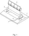
- Fig. 1 presents in a simplified oblique top view an advantageous embodiment of the wave energy recovery apparatus according to the invention.
- the wave energy recovery apparatus comprises at least a base 1, a hinged panel 2 reciprocating about the center axis of its pivot shaft.
- the rotation angle of the panel 2 is at maximum ⁇ 90o from the vertical position.
- a transmission line 5 is used to transmit the produced electricity to further use.
- the reciprocating panel 2 oscillates on the base 1 back and forth with the movement of seawater for recovering kinetic energy like wave energy of seawater.
- the panel 2 and the tubular shaft 4 rotate back and forth together simultaneously and at the same speed of rotation.
- the base 1 is preferably mounted onto the bottom of the sea, but it can also be near the bottom supported by pillars.
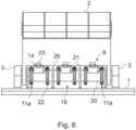
- Figs. 6-10 present the advantageous embodiment of the wave energy recovery apparatus according to Fig. 1 in more detail.
- the arrangement is presented in a side view and in a simplified and diagrammatic way.
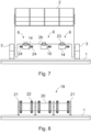
- Fig. 7 presents in a side view and in a simplified and diagrammatic way the reciprocating panel 2 with generators 14 according to the arrangement of Fig. 6 .
- Fig. 8 presents in a side view and in a simplified and diagrammatic way the motionless lower part 19 of the arrangement according to Fig. 6
- Fig. 9 presents in a top view and in a simplified and diagrammatic way and partially cross-sectioned the wave recovery arrangement according to Fig. 6
- Fig. 10 presents in a simplified and diagrammatic way the wave recovery arrangement according to Fig. 6 seen cross-sectioned along the line A-A in Fig. 9 .
- the wave energy recovery apparatus comprises a reciprocating hinged panel 2.
- the panel is fitted at its ends with bearings that are in bearing housings 3 located at the ends of the panel 2.
- the bearing housings 3 are fastened to the base 1.
- the panel 2 has a downwards opening recess 2b that is almost as wide as the panel 2.
- the recess 2b makes room for the motionless lower part 19 of the arrangement.
- the panel 2 is able to make a reciprocating rotational motion partially around the motionless lower part 19.
- the arrangement according to the invention comprises six generators 14 that are fastened to the lower edge of the panel 2 with fastening elements 23.
- the generators 14 may be more or less than six but, however, always an even number, for example 2, 4, 8, 10, 12 or even more.
- the first half of the generators 14 are fastened to the first side of the panel 2 and the second half of the generators 14 are fastened to the second side of the same panel 2.
- each generator 14 comprises a gearwheel 24 of relatively small diameter and a one-way clutch mechanism 10, which both are mounted on the same axle.
- the one-way clutch mechanism 10 is operatively coupled between the generator axle and the gearwheel 24 axle and is arranged to allow the generator axle to rotate only to one direction, either clockwise or counterclockwise.
- the generators 14 on the first side of the panel 2 are in reverse direction compared to the generators 14 on the second side of the panel 2.
- gearwheels 24 of the generators 14 on the first side of the panel 2 are directed towards the second end of the panel 2
- gearwheels 24 of the generators 14 on the second side of the panel 2 are directed towards the first end of the panel 2. In that case, there is more room to arrange the gear assembly.
- Fig.7 only four generators 14 are presented in Fig.7 .
- Fig. 8 presents in a side view and in a simplified and diagrammatic way the motionless lower part 19 of the arrangement according to Fig.6 .
- the lower part 19 comprises a tubular shaft 20 that is supported and fastened to the base 1 with support legs 21.
- the tubular shaft 20 comprises on its outer circumference a number of motionless gear rims 22, in this case six substantially similar gear rims 22, one for each generator 14.
- the gear rims 22 are arranged to mesh with the gearwheels 24 of the generators.
- the gear rims 22 and the gearwheels 24 meshing with each other form a gear transmission 11a for the generators 14 of the arrangement according to the invention.
- the diameter of the gear rims 22 is relatively big compared to the diameter of the gearwheels 24. Therefore, the transmission ratio between the gear rim 22 and the gearwheel 24 is relatively great.
- the transmission ratio is greater than 10, suitably greater than 50 and preferably greater than 100. The greater the transmission ratio the faster the generators 14 rotate when the panel 2 makes its relatively slow reciprocating motion.
- the arrangement comprises at least two PTO units 6 that each may comprise one or more generators 14.
- the generators are relatively small in size and arranged to be rotated fast by different types of gear transmissions. For example, when the generators 14 are rotated through a gear transmission the transmission ratio is greater than 10, suitably greater than 50 and preferably greater than 100. The greater the transmission ratio the faster the generators 14 rotate when the panel 2 makes its relatively slow reciprocating motion.
- a half of the generators 14 are rotated only to one direction and another half of the generators 14 are rotated only to the opposite direction.
- the first half of the generators 14 are rotated, for example, clockwise and the second half of the generators 14 are rotated counterclockwise, or vice versa.
- the first half of the generators 14 are rotated when the panel 2 makes its reciprocating movement to the first direction
- the second half of the generators 14 are rotated when the panel 2 makes its reciprocating movement to the second direction that is opposite to the movement of the first direction.
- This kind of operation is arranged by the use of one-way clutch mechanisms 10 that are placed between the movement of the panel 2 and the rotation of the axles of the generators 14.
Landscapes
- Engineering & Computer Science (AREA)
- Chemical & Material Sciences (AREA)
- Combustion & Propulsion (AREA)
- Mechanical Engineering (AREA)
- General Engineering & Computer Science (AREA)
- Life Sciences & Earth Sciences (AREA)
- General Life Sciences & Earth Sciences (AREA)
- Oceanography (AREA)
- Other Liquid Machine Or Engine Such As Wave Power Use (AREA)
Claims (7)
- Wellenenergie-Rückgewinnungsvorrichtung mit einer Zapfwellenanordnung, die mindestens eine Basis (1), eine sich hin- und herbewegende Platte (2), die sich in eine Richtung und in eine entgegengesetzte Richtung drehen kann, zwei Zapfwelleneinheiten (6), wobei jede Zapfwelleneinheit einen oder mehrere Generatoren (14) zur Umwandlung der kinetischen Energie von Wellen oder Gezeitenströmungen in Elektrizität umfasst, und mindestens zwei Zahnradgetriebe (11a) und mindestens zwei Einweg-Kupplungsmechanismen (10), wobei die Zahnradgetriebe (11a) und die Einweg-Kupplungsmechanismen (10) funktionsmäßig zwischen der Platte (2) und den Generatoren (14) angeschlossen sind, und die Platte (2) so angeordnet ist, dass sie eine Hälfte der Zahnräder und Generatoren (14) dreht, wenn sich die Platte (2) in die eine Richtung dreht, und eine andere Hälfte der Zahnräder und Generatoren (14), wenn sich die Platte (2) in die entgegengesetzte Richtung dreht, dadurch gekennzeichnet, dass zwei oder mehr Generatoren (14) an einer unteren Kante der Platte (2) befestigt und so angeordnet sind, dass sie durch die Platte (2) gedreht werden, und dass die Vorrichtung ein Zahnradgetriebe (11a) für jeden Generator (14) umfasst, wobei das Zahnradgetriebe (11a) einen bewegungslosen Zahnkranz (22) umfasst, der mit einem Zahnrad (24) kämmt, das mit einer Drehachse des Generators (14) gekoppelt ist.
- Wellenenergie-Rückgewinnungsvorrichtung nach Anspruch 1, ist dadurch gekennzeichnet, dass die Drehrichtung jedes Getriebes mit einem Einweg-Kupplungsmechanismus (10) gesteuert wird.
- Wellenenergie-Rückgewinnungsvorrichtung nach Anspruch 1 oder 2, ist dadurch gekennzeichnet, dass jedes Getriebe (11a) mit einem Übersetzungsverhältnis ausgestattet ist, das zwischen der Drehbewegung der Platte (2) und der Drehachse des Generators (14) wirkt, wobei das Übersetzungsverhältnis größer als 10, geeigneterweise größer als 50 und vorzugsweise größer als 100 ist.
- Wellenenergie-Rückgewinnungsvorrichtung nach einem der vorstehenden Ansprüche, ist dadurch gekennzeichnet, dass jeder Einweg-Kupplungsmechanismus (10) zwischen dem Zahnrad (24) des Zahnradgetriebes (11a) und der Drehachse des Generators (14) funktionsfähig verbunden ist.
- Wellenenergie-Rückgewinnungsvorrichtung nach einem der vorstehenden Ansprüche, ist dadurch gekennzeichnet, dass eine Hälfte der Generatoren (14) an einer ersten Seite der Platte (2) und eine andere Hälfte der Generatoren (14) an einer zweiten Seite der Platte (2) befestigt ist.
- Wellenenergie-Rückgewinnungsvorrichtung nach einem der vorstehenden Ansprüche, ist dadurch gekennzeichnet, dass die Zahnkränze (22) des Zahnradgetriebes (11a) auf einer bewegungslosen rohrförmigen Welle (20) befestigt sind, die mit Stützbeinen (21) an der Basis (1) befestigt ist.
- Wellenenergie-Rückgewinnungsvorrichtung nach einem der vorstehenden Ansprüche, ist dadurch gekennzeichnet s jeder Einweg-Kupplungsmechanismus (10) eine Freilaufkupplung ist.
Priority Applications (1)
| Application Number | Priority Date | Filing Date | Title |
|---|---|---|---|
| EP22189219.3A EP4112917B1 (de) | 2018-05-30 | 2018-05-30 | Wellenenergierückgewinnungsvorrichtung mit zapfwellenanordnung |
Applications Claiming Priority (3)
| Application Number | Priority Date | Filing Date | Title |
|---|---|---|---|
| EP18920566.9A EP3803100B1 (de) | 2018-05-30 | 2018-05-30 | Wellenenergierückgewinnungsvorrichtung mit zapfwellenanordnung |
| PCT/FI2018/050407 WO2019229290A1 (en) | 2018-05-30 | 2018-05-30 | Wave energy recovery apparatus with power-take-off arrangement |
| EP22189219.3A EP4112917B1 (de) | 2018-05-30 | 2018-05-30 | Wellenenergierückgewinnungsvorrichtung mit zapfwellenanordnung |
Related Parent Applications (2)
| Application Number | Title | Priority Date | Filing Date |
|---|---|---|---|
| EP18920566.9A Division EP3803100B1 (de) | 2018-05-30 | 2018-05-30 | Wellenenergierückgewinnungsvorrichtung mit zapfwellenanordnung |
| EP18920566.9A Division-Into EP3803100B1 (de) | 2018-05-30 | 2018-05-30 | Wellenenergierückgewinnungsvorrichtung mit zapfwellenanordnung |
Publications (2)
| Publication Number | Publication Date |
|---|---|
| EP4112917A1 EP4112917A1 (de) | 2023-01-04 |
| EP4112917B1 true EP4112917B1 (de) | 2024-09-04 |
Family
ID=68697867
Family Applications (3)
| Application Number | Title | Priority Date | Filing Date |
|---|---|---|---|
| EP18920566.9A Active EP3803100B1 (de) | 2018-05-30 | 2018-05-30 | Wellenenergierückgewinnungsvorrichtung mit zapfwellenanordnung |
| EP22189253.2A Active EP4112918B1 (de) | 2018-05-30 | 2018-05-30 | Wellenenergierückgewinnungsvorrichtung mit zapfwellenanordnung |
| EP22189219.3A Active EP4112917B1 (de) | 2018-05-30 | 2018-05-30 | Wellenenergierückgewinnungsvorrichtung mit zapfwellenanordnung |
Family Applications Before (2)
| Application Number | Title | Priority Date | Filing Date |
|---|---|---|---|
| EP18920566.9A Active EP3803100B1 (de) | 2018-05-30 | 2018-05-30 | Wellenenergierückgewinnungsvorrichtung mit zapfwellenanordnung |
| EP22189253.2A Active EP4112918B1 (de) | 2018-05-30 | 2018-05-30 | Wellenenergierückgewinnungsvorrichtung mit zapfwellenanordnung |
Country Status (4)
| Country | Link |
|---|---|
| US (3) | US11493016B2 (de) |
| EP (3) | EP3803100B1 (de) |
| CN (3) | CN115788750A (de) |
| WO (1) | WO2019229290A1 (de) |
Families Citing this family (3)
| Publication number | Priority date | Publication date | Assignee | Title |
|---|---|---|---|---|
| CN115788750A (zh) * | 2018-05-30 | 2023-03-14 | Aw能源有限公司 | 具有动力输出装置的波浪能回收利用设备 |
| CN111022242B (zh) * | 2019-12-23 | 2021-04-02 | 武汉理工大学 | 一种综合利用波浪能与海流能的发电装置 |
| WO2021205056A1 (en) * | 2020-04-07 | 2021-10-14 | Aw-Energy Oy | Coupling arrangement in a wave energy recovery apparatus |
Family Cites Families (33)
| Publication number | Priority date | Publication date | Assignee | Title |
|---|---|---|---|---|
| US1925742A (en) * | 1932-04-21 | 1933-09-05 | Robert F Bamber | Wave motor |
| JPH07229470A (ja) * | 1993-12-24 | 1995-08-29 | Suke Ishii | 波動動力機械 |
| FI20012086A0 (fi) | 2001-10-26 | 2001-10-26 | Top Shark Oy | Menetelmä ja laitteisto aaltoenergian hyödyntämiseksi |
| PT103270A (pt) | 2005-05-02 | 2005-09-30 | Martifer En Equipamentos Para | Sistema de conversao/inversao de energia |
| KR200400674Y1 (ko) | 2005-08-23 | 2005-11-08 | 현 용 이 | 파력발전기 |
| KR200406674Y1 (ko) | 2005-09-20 | 2006-01-24 | 공현식 | 노트북 컴퓨터를 이용한 서버 또는 개인용 컴퓨터의 입출력 에뮬레이션 장치 |
| GB0608128D0 (en) * | 2006-04-25 | 2006-06-07 | Mccague James | Movement and power generation apparatus |
| FI119791B (fi) | 2007-02-15 | 2009-03-13 | Aw Energy Oy | Lineaarigeneraattori |
| US7759813B2 (en) * | 2007-08-23 | 2010-07-20 | Tetsuhiko Fujisato | Gravity wave power generation apparatus |
| US9551125B2 (en) * | 2009-03-26 | 2017-01-24 | Aw-Energy Oy | Method for installing and servicing an apparatus recovering the kinetic energy of water, and an apparatus recovering the kinetic energy of water |
| US9528900B2 (en) * | 2009-09-19 | 2016-12-27 | Bruce Gregory | Balanced and eccentric mass compact pendulum with dynamic tuning |
| ITMI20100119A1 (it) | 2010-01-28 | 2011-07-29 | Resnova S R L | Dispositivo per generare energia elettrica dal moto ondoso |
| EP2553260B1 (de) | 2010-03-31 | 2018-11-28 | AW-Energy Oy | Wellenenergiegewinnungssystem |
| US7964984B2 (en) * | 2010-04-01 | 2011-06-21 | Saavedra John A | Electric power generator utilizing intermittent wind |
| EP2556241A4 (de) | 2010-04-07 | 2018-01-10 | Ocean Harvesting Technologies AB | Wellenenergiewandler und getriebe |
| WO2012053899A1 (en) | 2010-10-21 | 2012-04-26 | Langlee Wave Power As | Wave power device with generator |
| CN202360291U (zh) * | 2011-12-09 | 2012-08-01 | 大连海洋大学 | 水动摆波浪能发电装置 |
| WO2013188397A1 (en) * | 2012-06-12 | 2013-12-19 | Resolute Marine Energy, Inc. | Linear array of wave-energy converters |
| KR20130034644A (ko) * | 2012-11-19 | 2013-04-05 | 김재운 | 파력 발전 장치 |
| WO2014162037A1 (en) | 2013-04-05 | 2014-10-09 | Aw-Energy Oy | Submersible wave energy conversion unit |
| US8745981B1 (en) * | 2013-10-10 | 2014-06-10 | John Clark Hanna | Ocean powered take-off for multiple rotary drives |
| EP3084208A4 (de) * | 2013-12-05 | 2017-11-15 | AW-Energy Oy | Wellenenergieumwandler |
| EP3097306A1 (de) * | 2014-01-08 | 2016-11-30 | AW-Energy Oy | Oberflächenpegelverfolgungsanordnung für ein wellenenergierückgewinnungssystem |
| CN103994017B (zh) * | 2014-01-28 | 2016-08-24 | 浙江海洋学院 | 一种利用船身摆动的钟摆发电装置 |
| WO2015177400A1 (en) * | 2014-05-22 | 2015-11-26 | Aw-Energy Oy | Energy transfer arrangement of a wave energy recovery apparatus |
| US10364790B2 (en) * | 2014-06-18 | 2019-07-30 | Aw-Energy Oy | Wave energy recovery apparatus with an energy transfer arrangement |
| KR101584187B1 (ko) * | 2015-05-18 | 2016-01-22 | 정민시 | 파력 발전장치 |
| WO2017029425A1 (en) * | 2015-08-18 | 2017-02-23 | Aw-Energy Oy | Arrangement in a wave energy recovery apparatus |
| CN205001117U (zh) * | 2015-09-26 | 2016-01-27 | 哈尔滨工程大学 | 双摆式波浪能发电单元结构 |
| WO2017062528A2 (en) | 2015-10-05 | 2017-04-13 | Rohrer Technologies, Inc. | Multi mode wave energy converter with elongated wave front parallel float having integral lower shoaling extension |
| WO2017174858A1 (en) * | 2016-04-08 | 2017-10-12 | Aw-Energy Oy | Arrangement in a wave energy recovery apparatus and method for operating a wave energy recovery apparatus |
| RU2655418C2 (ru) * | 2016-07-13 | 2018-05-28 | Федеральное государственное автономное образовательное учреждение высшего образования "Севастопольский государственный университет" | Устройство для преобразования энергии волн |
| CN115788750A (zh) * | 2018-05-30 | 2023-03-14 | Aw能源有限公司 | 具有动力输出装置的波浪能回收利用设备 |
-
2018
- 2018-05-30 CN CN202211417160.7A patent/CN115788750A/zh active Pending
- 2018-05-30 CN CN201880095221.8A patent/CN112400059B/zh active Active
- 2018-05-30 WO PCT/FI2018/050407 patent/WO2019229290A1/en not_active Ceased
- 2018-05-30 EP EP18920566.9A patent/EP3803100B1/de active Active
- 2018-05-30 EP EP22189253.2A patent/EP4112918B1/de active Active
- 2018-05-30 EP EP22189219.3A patent/EP4112917B1/de active Active
- 2018-05-30 US US17/059,846 patent/US11493016B2/en active Active
- 2018-05-30 CN CN202211417040.7A patent/CN115638076A/zh active Pending
-
2022
- 2022-08-17 US US17/889,839 patent/US11719218B2/en active Active
- 2022-08-17 US US17/889,888 patent/US11698051B2/en active Active
Also Published As
| Publication number | Publication date |
|---|---|
| US20210222666A1 (en) | 2021-07-22 |
| EP4112917A1 (de) | 2023-01-04 |
| EP3803100A4 (de) | 2022-01-05 |
| US11493016B2 (en) | 2022-11-08 |
| US11698051B2 (en) | 2023-07-11 |
| EP3803100A1 (de) | 2021-04-14 |
| EP4112918B1 (de) | 2024-07-10 |
| US20220389898A1 (en) | 2022-12-08 |
| EP3803100B1 (de) | 2024-01-03 |
| CN115638076A (zh) | 2023-01-24 |
| CN112400059A (zh) | 2021-02-23 |
| WO2019229290A1 (en) | 2019-12-05 |
| EP3803100C0 (de) | 2024-01-03 |
| CN112400059B (zh) | 2023-02-28 |
| CN115788750A (zh) | 2023-03-14 |
| US20220389899A1 (en) | 2022-12-08 |
| EP4112918C0 (de) | 2024-07-10 |
| EP4112918A1 (de) | 2023-01-04 |
| US11719218B2 (en) | 2023-08-08 |
Similar Documents
| Publication | Publication Date | Title |
|---|---|---|
| US11719218B2 (en) | Wave energy recovery apparatus with power-take-off arrangement | |
| KR100752510B1 (ko) | 단일 메인베어링을 갖는 풍력 발전기 | |
| US8198749B2 (en) | Wind turbine generator | |
| EP2640964B1 (de) | Vorrichtung zur umwandlung der kraft von meereswellenbewegung | |
| US20120091725A1 (en) | Wind turbine generator | |
| US20110245031A1 (en) | Bogie plate for wind turbine | |
| US20160369766A1 (en) | Wave energy conversion apparatus | |
| CN101981315B (zh) | 风力发电装置的螺距驱动装置及风力发电装置 | |
| EP1904689A1 (de) | Schaufelanstellwinkelsteuermechanismus | |
| DK173801B1 (da) | Vindkraftværk og fremgangsmåde ved drift af kraftværkets elektrogenerator | |
| WO2009091261A2 (en) | Wind turbine device | |
| CN108591400B (zh) | 动力传输装置及包括这种动力传输装置的风力机 | |
| JP4546097B2 (ja) | 風力発電装置 | |
| JP4909578B2 (ja) | 風車用駆動装置 | |
| KR101269965B1 (ko) | 풍력발전기 | |
| AU2006272437B2 (en) | A blade pitch control mechanism | |
| EP2884102B1 (de) | Getriebe für eine Windkraftanlage | |
| CN117366184A (zh) | 一种高效能水平对置式动力装置 | |
| CN121488106A (zh) | 用于风力涡轮机的传动系以及风力涡轮机 | |
| KR20210062871A (ko) | 복수의 팬 날개를 구비하는 풍력 발전기 |
Legal Events
| Date | Code | Title | Description |
|---|---|---|---|
| PUAI | Public reference made under article 153(3) epc to a published international application that has entered the european phase |
Free format text: ORIGINAL CODE: 0009012 |
|
| STAA | Information on the status of an ep patent application or granted ep patent |
Free format text: STATUS: THE APPLICATION HAS BEEN PUBLISHED |
|
| AC | Divisional application: reference to earlier application |
Ref document number: 3803100 Country of ref document: EP Kind code of ref document: P |
|
| AK | Designated contracting states |
Kind code of ref document: A1 Designated state(s): AL AT BE BG CH CY CZ DE DK EE ES FI FR GB GR HR HU IE IS IT LI LT LU LV MC MK MT NL NO PL PT RO RS SE SI SK SM TR |
|
| STAA | Information on the status of an ep patent application or granted ep patent |
Free format text: STATUS: REQUEST FOR EXAMINATION WAS MADE |
|
| 17P | Request for examination filed |
Effective date: 20230630 |
|
| RBV | Designated contracting states (corrected) |
Designated state(s): AL AT BE BG CH CY CZ DE DK EE ES FI FR GB GR HR HU IE IS IT LI LT LU LV MC MK MT NL NO PL PT RO RS SE SI SK SM TR |
|
| GRAP | Despatch of communication of intention to grant a patent |
Free format text: ORIGINAL CODE: EPIDOSNIGR1 |
|
| STAA | Information on the status of an ep patent application or granted ep patent |
Free format text: STATUS: GRANT OF PATENT IS INTENDED |
|
| INTG | Intention to grant announced |
Effective date: 20240327 |
|
| GRAS | Grant fee paid |
Free format text: ORIGINAL CODE: EPIDOSNIGR3 |
|
| GRAA | (expected) grant |
Free format text: ORIGINAL CODE: 0009210 |
|
| STAA | Information on the status of an ep patent application or granted ep patent |
Free format text: STATUS: THE PATENT HAS BEEN GRANTED |
|
| AC | Divisional application: reference to earlier application |
Ref document number: 3803100 Country of ref document: EP Kind code of ref document: P |
|
| AK | Designated contracting states |
Kind code of ref document: B1 Designated state(s): AL AT BE BG CH CY CZ DE DK EE ES FI FR GB GR HR HU IE IS IT LI LT LU LV MC MK MT NL NO PL PT RO RS SE SI SK SM TR |
|
| REG | Reference to a national code |
Ref country code: GB Ref legal event code: FG4D |
|
| REG | Reference to a national code |
Ref country code: CH Ref legal event code: EP |
|
| REG | Reference to a national code |
Ref country code: IE Ref legal event code: FG4D |
|
| REG | Reference to a national code |
Ref country code: DE Ref legal event code: R096 Ref document number: 602018074166 Country of ref document: DE |
|
| REG | Reference to a national code |
Ref country code: LT Ref legal event code: MG9D |
|
| REG | Reference to a national code |
Ref country code: NL Ref legal event code: MP Effective date: 20240904 |
|
| PG25 | Lapsed in a contracting state [announced via postgrant information from national office to epo] |
Ref country code: NO Free format text: LAPSE BECAUSE OF FAILURE TO SUBMIT A TRANSLATION OF THE DESCRIPTION OR TO PAY THE FEE WITHIN THE PRESCRIBED TIME-LIMIT Effective date: 20241204 |
|
| PG25 | Lapsed in a contracting state [announced via postgrant information from national office to epo] |
Ref country code: GR Free format text: LAPSE BECAUSE OF FAILURE TO SUBMIT A TRANSLATION OF THE DESCRIPTION OR TO PAY THE FEE WITHIN THE PRESCRIBED TIME-LIMIT Effective date: 20241205 Ref country code: FI Free format text: LAPSE BECAUSE OF FAILURE TO SUBMIT A TRANSLATION OF THE DESCRIPTION OR TO PAY THE FEE WITHIN THE PRESCRIBED TIME-LIMIT Effective date: 20240904 |
|
| PG25 | Lapsed in a contracting state [announced via postgrant information from national office to epo] |
Ref country code: BG Free format text: LAPSE BECAUSE OF FAILURE TO SUBMIT A TRANSLATION OF THE DESCRIPTION OR TO PAY THE FEE WITHIN THE PRESCRIBED TIME-LIMIT Effective date: 20240904 |
|
| PG25 | Lapsed in a contracting state [announced via postgrant information from national office to epo] |
Ref country code: LV Free format text: LAPSE BECAUSE OF FAILURE TO SUBMIT A TRANSLATION OF THE DESCRIPTION OR TO PAY THE FEE WITHIN THE PRESCRIBED TIME-LIMIT Effective date: 20240904 |
|
| PG25 | Lapsed in a contracting state [announced via postgrant information from national office to epo] |
Ref country code: HR Free format text: LAPSE BECAUSE OF FAILURE TO SUBMIT A TRANSLATION OF THE DESCRIPTION OR TO PAY THE FEE WITHIN THE PRESCRIBED TIME-LIMIT Effective date: 20240904 |
|
| PG25 | Lapsed in a contracting state [announced via postgrant information from national office to epo] |
Ref country code: RS Free format text: LAPSE BECAUSE OF FAILURE TO SUBMIT A TRANSLATION OF THE DESCRIPTION OR TO PAY THE FEE WITHIN THE PRESCRIBED TIME-LIMIT Effective date: 20241204 Ref country code: ES Free format text: LAPSE BECAUSE OF FAILURE TO SUBMIT A TRANSLATION OF THE DESCRIPTION OR TO PAY THE FEE WITHIN THE PRESCRIBED TIME-LIMIT Effective date: 20240904 |
|
| PG25 | Lapsed in a contracting state [announced via postgrant information from national office to epo] |
Ref country code: RS Free format text: LAPSE BECAUSE OF FAILURE TO SUBMIT A TRANSLATION OF THE DESCRIPTION OR TO PAY THE FEE WITHIN THE PRESCRIBED TIME-LIMIT Effective date: 20241204 Ref country code: NO Free format text: LAPSE BECAUSE OF FAILURE TO SUBMIT A TRANSLATION OF THE DESCRIPTION OR TO PAY THE FEE WITHIN THE PRESCRIBED TIME-LIMIT Effective date: 20241204 Ref country code: LV Free format text: LAPSE BECAUSE OF FAILURE TO SUBMIT A TRANSLATION OF THE DESCRIPTION OR TO PAY THE FEE WITHIN THE PRESCRIBED TIME-LIMIT Effective date: 20240904 Ref country code: HR Free format text: LAPSE BECAUSE OF FAILURE TO SUBMIT A TRANSLATION OF THE DESCRIPTION OR TO PAY THE FEE WITHIN THE PRESCRIBED TIME-LIMIT Effective date: 20240904 Ref country code: GR Free format text: LAPSE BECAUSE OF FAILURE TO SUBMIT A TRANSLATION OF THE DESCRIPTION OR TO PAY THE FEE WITHIN THE PRESCRIBED TIME-LIMIT Effective date: 20241205 Ref country code: FI Free format text: LAPSE BECAUSE OF FAILURE TO SUBMIT A TRANSLATION OF THE DESCRIPTION OR TO PAY THE FEE WITHIN THE PRESCRIBED TIME-LIMIT Effective date: 20240904 Ref country code: ES Free format text: LAPSE BECAUSE OF FAILURE TO SUBMIT A TRANSLATION OF THE DESCRIPTION OR TO PAY THE FEE WITHIN THE PRESCRIBED TIME-LIMIT Effective date: 20240904 Ref country code: BG Free format text: LAPSE BECAUSE OF FAILURE TO SUBMIT A TRANSLATION OF THE DESCRIPTION OR TO PAY THE FEE WITHIN THE PRESCRIBED TIME-LIMIT Effective date: 20240904 |
|
| REG | Reference to a national code |
Ref country code: AT Ref legal event code: MK05 Ref document number: 1720637 Country of ref document: AT Kind code of ref document: T Effective date: 20240904 |
|
| PG25 | Lapsed in a contracting state [announced via postgrant information from national office to epo] |
Ref country code: NL Free format text: LAPSE BECAUSE OF FAILURE TO SUBMIT A TRANSLATION OF THE DESCRIPTION OR TO PAY THE FEE WITHIN THE PRESCRIBED TIME-LIMIT Effective date: 20240904 |
|
| PG25 | Lapsed in a contracting state [announced via postgrant information from national office to epo] |
Ref country code: PT Free format text: LAPSE BECAUSE OF FAILURE TO SUBMIT A TRANSLATION OF THE DESCRIPTION OR TO PAY THE FEE WITHIN THE PRESCRIBED TIME-LIMIT Effective date: 20250106 Ref country code: IS Free format text: LAPSE BECAUSE OF FAILURE TO SUBMIT A TRANSLATION OF THE DESCRIPTION OR TO PAY THE FEE WITHIN THE PRESCRIBED TIME-LIMIT Effective date: 20250104 |
|
| PG25 | Lapsed in a contracting state [announced via postgrant information from national office to epo] |
Ref country code: SM Free format text: LAPSE BECAUSE OF FAILURE TO SUBMIT A TRANSLATION OF THE DESCRIPTION OR TO PAY THE FEE WITHIN THE PRESCRIBED TIME-LIMIT Effective date: 20240904 Ref country code: RO Free format text: LAPSE BECAUSE OF FAILURE TO SUBMIT A TRANSLATION OF THE DESCRIPTION OR TO PAY THE FEE WITHIN THE PRESCRIBED TIME-LIMIT Effective date: 20240904 |
|
| PG25 | Lapsed in a contracting state [announced via postgrant information from national office to epo] |
Ref country code: EE Free format text: LAPSE BECAUSE OF FAILURE TO SUBMIT A TRANSLATION OF THE DESCRIPTION OR TO PAY THE FEE WITHIN THE PRESCRIBED TIME-LIMIT Effective date: 20240904 Ref country code: AT Free format text: LAPSE BECAUSE OF FAILURE TO SUBMIT A TRANSLATION OF THE DESCRIPTION OR TO PAY THE FEE WITHIN THE PRESCRIBED TIME-LIMIT Effective date: 20240904 |
|
| PG25 | Lapsed in a contracting state [announced via postgrant information from national office to epo] |
Ref country code: PL Free format text: LAPSE BECAUSE OF FAILURE TO SUBMIT A TRANSLATION OF THE DESCRIPTION OR TO PAY THE FEE WITHIN THE PRESCRIBED TIME-LIMIT Effective date: 20240904 Ref country code: CZ Free format text: LAPSE BECAUSE OF FAILURE TO SUBMIT A TRANSLATION OF THE DESCRIPTION OR TO PAY THE FEE WITHIN THE PRESCRIBED TIME-LIMIT Effective date: 20240904 |
|
| PG25 | Lapsed in a contracting state [announced via postgrant information from national office to epo] |
Ref country code: SK Free format text: LAPSE BECAUSE OF FAILURE TO SUBMIT A TRANSLATION OF THE DESCRIPTION OR TO PAY THE FEE WITHIN THE PRESCRIBED TIME-LIMIT Effective date: 20240904 Ref country code: IT Free format text: LAPSE BECAUSE OF FAILURE TO SUBMIT A TRANSLATION OF THE DESCRIPTION OR TO PAY THE FEE WITHIN THE PRESCRIBED TIME-LIMIT Effective date: 20240904 |
|
| REG | Reference to a national code |
Ref country code: DE Ref legal event code: R097 Ref document number: 602018074166 Country of ref document: DE |
|
| PG25 | Lapsed in a contracting state [announced via postgrant information from national office to epo] |
Ref country code: DK Free format text: LAPSE BECAUSE OF FAILURE TO SUBMIT A TRANSLATION OF THE DESCRIPTION OR TO PAY THE FEE WITHIN THE PRESCRIBED TIME-LIMIT Effective date: 20240904 |
|
| PGFP | Annual fee paid to national office [announced via postgrant information from national office to epo] |
Ref country code: GB Payment date: 20250520 Year of fee payment: 8 |
|
| PLBE | No opposition filed within time limit |
Free format text: ORIGINAL CODE: 0009261 |
|
| STAA | Information on the status of an ep patent application or granted ep patent |
Free format text: STATUS: NO OPPOSITION FILED WITHIN TIME LIMIT |
|
| 26N | No opposition filed |
Effective date: 20250605 |
|
| PG25 | Lapsed in a contracting state [announced via postgrant information from national office to epo] |
Ref country code: SE Free format text: LAPSE BECAUSE OF FAILURE TO SUBMIT A TRANSLATION OF THE DESCRIPTION OR TO PAY THE FEE WITHIN THE PRESCRIBED TIME-LIMIT Effective date: 20240904 |
|
| REG | Reference to a national code |
Ref country code: DE Ref legal event code: R119 Ref document number: 602018074166 Country of ref document: DE |
|
| REG | Reference to a national code |
Ref country code: CH Ref legal event code: H13 Free format text: ST27 STATUS EVENT CODE: U-0-0-H10-H13 (AS PROVIDED BY THE NATIONAL OFFICE) Effective date: 20251223 |
|
| PG25 | Lapsed in a contracting state [announced via postgrant information from national office to epo] |
Ref country code: LU Free format text: LAPSE BECAUSE OF NON-PAYMENT OF DUE FEES Effective date: 20250530 |
|
| PG25 | Lapsed in a contracting state [announced via postgrant information from national office to epo] |
Ref country code: CH Free format text: LAPSE BECAUSE OF NON-PAYMENT OF DUE FEES Effective date: 20250531 |
|
| REG | Reference to a national code |
Ref country code: BE Ref legal event code: MM Effective date: 20250531 |
|
| PG25 | Lapsed in a contracting state [announced via postgrant information from national office to epo] |
Ref country code: MC Free format text: LAPSE BECAUSE OF FAILURE TO SUBMIT A TRANSLATION OF THE DESCRIPTION OR TO PAY THE FEE WITHIN THE PRESCRIBED TIME-LIMIT Effective date: 20240904 |