EP4112516A1 - Electrode connection device and automated electrode connection method using same - Google Patents
Electrode connection device and automated electrode connection method using same Download PDFInfo
- Publication number
- EP4112516A1 EP4112516A1 EP21842468.7A EP21842468A EP4112516A1 EP 4112516 A1 EP4112516 A1 EP 4112516A1 EP 21842468 A EP21842468 A EP 21842468A EP 4112516 A1 EP4112516 A1 EP 4112516A1
- Authority
- EP
- European Patent Office
- Prior art keywords
- electrode
- electrode roll
- standby
- unit
- connection
- Prior art date
- Legal status (The legal status is an assumption and is not a legal conclusion. Google has not performed a legal analysis and makes no representation as to the accuracy of the status listed.)
- Granted
Links
Images


Classifications
-
- B—PERFORMING OPERATIONS; TRANSPORTING
- B65—CONVEYING; PACKING; STORING; HANDLING THIN OR FILAMENTARY MATERIAL
- B65H—HANDLING THIN OR FILAMENTARY MATERIAL, e.g. SHEETS, WEBS, CABLES
- B65H21/00—Apparatus for splicing webs
-
- B—PERFORMING OPERATIONS; TRANSPORTING
- B65—CONVEYING; PACKING; STORING; HANDLING THIN OR FILAMENTARY MATERIAL
- B65H—HANDLING THIN OR FILAMENTARY MATERIAL, e.g. SHEETS, WEBS, CABLES
- B65H19/00—Changing the web roll
- B65H19/10—Changing the web roll in unwinding mechanisms or in connection with unwinding operations
- B65H19/102—Preparing the leading end of the replacement web before splicing operation; Adhesive arrangements on leading end of replacement web; Tabs and adhesive tapes for splicing
-
- B—PERFORMING OPERATIONS; TRANSPORTING
- B65—CONVEYING; PACKING; STORING; HANDLING THIN OR FILAMENTARY MATERIAL
- B65H—HANDLING THIN OR FILAMENTARY MATERIAL, e.g. SHEETS, WEBS, CABLES
- B65H19/00—Changing the web roll
- B65H19/10—Changing the web roll in unwinding mechanisms or in connection with unwinding operations
- B65H19/18—Attaching, e.g. pasting, the replacement web to the expiring web
- B65H19/1805—Flying splicing, i.e. the expiring web moving during splicing contact
- B65H19/1826—Flying splicing, i.e. the expiring web moving during splicing contact taking place at a distance from the replacement roll
-
- B—PERFORMING OPERATIONS; TRANSPORTING
- B65—CONVEYING; PACKING; STORING; HANDLING THIN OR FILAMENTARY MATERIAL
- B65H—HANDLING THIN OR FILAMENTARY MATERIAL, e.g. SHEETS, WEBS, CABLES
- B65H19/00—Changing the web roll
- B65H19/10—Changing the web roll in unwinding mechanisms or in connection with unwinding operations
- B65H19/18—Attaching, e.g. pasting, the replacement web to the expiring web
- B65H19/1842—Attaching, e.g. pasting, the replacement web to the expiring web standing splicing, i.e. the expiring web being stationary during splicing contact
- B65H19/1852—Attaching, e.g. pasting, the replacement web to the expiring web standing splicing, i.e. the expiring web being stationary during splicing contact taking place at a distance from the replacement roll
-
- B—PERFORMING OPERATIONS; TRANSPORTING
- B65—CONVEYING; PACKING; STORING; HANDLING THIN OR FILAMENTARY MATERIAL
- B65H—HANDLING THIN OR FILAMENTARY MATERIAL, e.g. SHEETS, WEBS, CABLES
- B65H20/00—Advancing webs
- B65H20/16—Advancing webs by web-gripping means, e.g. grippers, clips
-
- B—PERFORMING OPERATIONS; TRANSPORTING
- B65—CONVEYING; PACKING; STORING; HANDLING THIN OR FILAMENTARY MATERIAL
- B65H—HANDLING THIN OR FILAMENTARY MATERIAL, e.g. SHEETS, WEBS, CABLES
- B65H35/00—Delivering articles from cutting or line-perforating machines; Article or web delivery apparatus incorporating cutting or line-perforating devices, e.g. adhesive tape dispensers
- B65H35/0006—Article or web delivery apparatus incorporating cutting or line-perforating devices
- B65H35/002—Hand-held or table apparatus
- B65H35/0026—Hand-held or table apparatus for delivering pressure-sensitive adhesive tape
- B65H35/0033—Hand-held or table apparatus for delivering pressure-sensitive adhesive tape and affixing it to a surface
-
- H—ELECTRICITY
- H01—ELECTRIC ELEMENTS
- H01M—PROCESSES OR MEANS, e.g. BATTERIES, FOR THE DIRECT CONVERSION OF CHEMICAL ENERGY INTO ELECTRICAL ENERGY
- H01M10/00—Secondary cells; Manufacture thereof
- H01M10/04—Construction or manufacture in general
- H01M10/0404—Machines for assembling batteries
-
- H—ELECTRICITY
- H01—ELECTRIC ELEMENTS
- H01M—PROCESSES OR MEANS, e.g. BATTERIES, FOR THE DIRECT CONVERSION OF CHEMICAL ENERGY INTO ELECTRICAL ENERGY
- H01M10/00—Secondary cells; Manufacture thereof
- H01M10/04—Construction or manufacture in general
- H01M10/0404—Machines for assembling batteries
- H01M10/0409—Machines for assembling batteries for cells with wound electrodes
-
- H—ELECTRICITY
- H01—ELECTRIC ELEMENTS
- H01M—PROCESSES OR MEANS, e.g. BATTERIES, FOR THE DIRECT CONVERSION OF CHEMICAL ENERGY INTO ELECTRICAL ENERGY
- H01M4/00—Electrodes
- H01M4/02—Electrodes composed of, or comprising, active material
- H01M4/04—Processes of manufacture in general
-
- B—PERFORMING OPERATIONS; TRANSPORTING
- B65—CONVEYING; PACKING; STORING; HANDLING THIN OR FILAMENTARY MATERIAL
- B65H—HANDLING THIN OR FILAMENTARY MATERIAL, e.g. SHEETS, WEBS, CABLES
- B65H2301/00—Handling processes for sheets or webs
- B65H2301/40—Type of handling process
- B65H2301/46—Splicing
- B65H2301/4606—Preparing leading edge for splicing
- B65H2301/46064—Preparing leading edge for splicing by transversally operated carriage
-
- B—PERFORMING OPERATIONS; TRANSPORTING
- B65—CONVEYING; PACKING; STORING; HANDLING THIN OR FILAMENTARY MATERIAL
- B65H—HANDLING THIN OR FILAMENTARY MATERIAL, e.g. SHEETS, WEBS, CABLES
- B65H2301/00—Handling processes for sheets or webs
- B65H2301/40—Type of handling process
- B65H2301/46—Splicing
- B65H2301/4606—Preparing leading edge for splicing
- B65H2301/4607—Preparing leading edge for splicing by adhesive tape
-
- B—PERFORMING OPERATIONS; TRANSPORTING
- B65—CONVEYING; PACKING; STORING; HANDLING THIN OR FILAMENTARY MATERIAL
- B65H—HANDLING THIN OR FILAMENTARY MATERIAL, e.g. SHEETS, WEBS, CABLES
- B65H2301/00—Handling processes for sheets or webs
- B65H2301/40—Type of handling process
- B65H2301/46—Splicing
- B65H2301/461—Processing webs in splicing process
- B65H2301/4611—Processing webs in splicing process before splicing
- B65H2301/46115—Processing webs in splicing process before splicing by bringing leading edge to splicing station, e.g. by chain or belt
-
- B—PERFORMING OPERATIONS; TRANSPORTING
- B65—CONVEYING; PACKING; STORING; HANDLING THIN OR FILAMENTARY MATERIAL
- B65H—HANDLING THIN OR FILAMENTARY MATERIAL, e.g. SHEETS, WEBS, CABLES
- B65H2301/00—Handling processes for sheets or webs
- B65H2301/40—Type of handling process
- B65H2301/46—Splicing
- B65H2301/461—Processing webs in splicing process
- B65H2301/4613—Processing webs in splicing process during splicing
-
- B—PERFORMING OPERATIONS; TRANSPORTING
- B65—CONVEYING; PACKING; STORING; HANDLING THIN OR FILAMENTARY MATERIAL
- B65H—HANDLING THIN OR FILAMENTARY MATERIAL, e.g. SHEETS, WEBS, CABLES
- B65H2301/00—Handling processes for sheets or webs
- B65H2301/40—Type of handling process
- B65H2301/46—Splicing
- B65H2301/461—Processing webs in splicing process
- B65H2301/4615—Processing webs in splicing process after splicing
- B65H2301/4617—Processing webs in splicing process after splicing cutting webs in splicing process
- B65H2301/46171—Processing webs in splicing process after splicing cutting webs in splicing process cutting leading edge of new web, e.g. manually
-
- B—PERFORMING OPERATIONS; TRANSPORTING
- B65—CONVEYING; PACKING; STORING; HANDLING THIN OR FILAMENTARY MATERIAL
- B65H—HANDLING THIN OR FILAMENTARY MATERIAL, e.g. SHEETS, WEBS, CABLES
- B65H2301/00—Handling processes for sheets or webs
- B65H2301/40—Type of handling process
- B65H2301/46—Splicing
- B65H2301/462—Form of splice
- B65H2301/4622—Abutting article or web portions, i.e. edge to edge
-
- B—PERFORMING OPERATIONS; TRANSPORTING
- B65—CONVEYING; PACKING; STORING; HANDLING THIN OR FILAMENTARY MATERIAL
- B65H—HANDLING THIN OR FILAMENTARY MATERIAL, e.g. SHEETS, WEBS, CABLES
- B65H2301/00—Handling processes for sheets or webs
- B65H2301/40—Type of handling process
- B65H2301/46—Splicing
- B65H2301/463—Splicing splicing means, i.e. means by which a web end is bound to another web end
- B65H2301/4631—Adhesive tape
-
- B—PERFORMING OPERATIONS; TRANSPORTING
- B65—CONVEYING; PACKING; STORING; HANDLING THIN OR FILAMENTARY MATERIAL
- B65H—HANDLING THIN OR FILAMENTARY MATERIAL, e.g. SHEETS, WEBS, CABLES
- B65H2301/00—Handling processes for sheets or webs
- B65H2301/40—Type of handling process
- B65H2301/46—Splicing
- B65H2301/463—Splicing splicing means, i.e. means by which a web end is bound to another web end
- B65H2301/4631—Adhesive tape
- B65H2301/46314—Pieces of adhesive tape, e.g. labels
-
- B—PERFORMING OPERATIONS; TRANSPORTING
- B65—CONVEYING; PACKING; STORING; HANDLING THIN OR FILAMENTARY MATERIAL
- B65H—HANDLING THIN OR FILAMENTARY MATERIAL, e.g. SHEETS, WEBS, CABLES
- B65H2701/00—Handled material; Storage means
- B65H2701/10—Handled articles or webs
- B65H2701/19—Specific article or web
-
- B—PERFORMING OPERATIONS; TRANSPORTING
- B65—CONVEYING; PACKING; STORING; HANDLING THIN OR FILAMENTARY MATERIAL
- B65H—HANDLING THIN OR FILAMENTARY MATERIAL, e.g. SHEETS, WEBS, CABLES
- B65H2701/00—Handled material; Storage means
- B65H2701/30—Handled filamentary material
- B65H2701/37—Tapes
- B65H2701/377—Adhesive tape
-
- B—PERFORMING OPERATIONS; TRANSPORTING
- B65—CONVEYING; PACKING; STORING; HANDLING THIN OR FILAMENTARY MATERIAL
- B65H—HANDLING THIN OR FILAMENTARY MATERIAL, e.g. SHEETS, WEBS, CABLES
- B65H2801/00—Application field
- B65H2801/72—Fuel cell manufacture
-
- Y—GENERAL TAGGING OF NEW TECHNOLOGICAL DEVELOPMENTS; GENERAL TAGGING OF CROSS-SECTIONAL TECHNOLOGIES SPANNING OVER SEVERAL SECTIONS OF THE IPC; TECHNICAL SUBJECTS COVERED BY FORMER USPC CROSS-REFERENCE ART COLLECTIONS [XRACs] AND DIGESTS
- Y02—TECHNOLOGIES OR APPLICATIONS FOR MITIGATION OR ADAPTATION AGAINST CLIMATE CHANGE
- Y02E—REDUCTION OF GREENHOUSE GAS [GHG] EMISSIONS, RELATED TO ENERGY GENERATION, TRANSMISSION OR DISTRIBUTION
- Y02E60/00—Enabling technologies; Technologies with a potential or indirect contribution to GHG emissions mitigation
- Y02E60/10—Energy storage using batteries
Definitions
- the present invention relates to an electrode connection apparatus and an electrode connection automation method using the same, and more particularly to an electrode connection apparatus capable of automatically connecting a new standby electrode roll to an end of a moving electrode roll during an electrode manufacturing process performed as a roll-to-roll process and an electrode connection automation method using the same.
- a lithium secondary battery which is capable of being charged and discharged, has been widely used as an energy source for wireless mobile devices or wearable devices, which are worn on bodies, and has also been used as an energy source for electric vehicles and hybrid electric vehicles presented as alternatives to existing gasoline and diesel vehicles, which cause air pollution.
- a positive electrode and a negative electrode are stacked in the state in which a separator is interposed therebetween, and lithium ions move between the positive electrode and the negative electrode, whereby the lithium secondary battery is repeatedly charged and discharged.
- a process of manufacturing an electrode including the positive electrode and the negative electrode includes a step of coating the remaining part of an electrode sheet wound in the form of a roll, excluding parts at which electrode tabs are to be formed, with an electrode agent, a step of drying and rolling the electrode agent, a step of slitting the electrode sheet, and a step of notching the slit electrode sheet into unit electrodes.
- An electrode manufacturing process is performed as a roll-to-roll continuous process.
- a worker stops equipment connects an edge of the electrode roll that is being used and an edge of a new electrode roll to each other using a tape, and reoperates the equipment.
- Patent Document 1 discloses an electrode production system for secondary batteries capable of connecting a first electrode material mounted to a first electrode material supply reel and a second electrode material mounted to a second electrode material supply reel to each other in order to perform a continuous process, but does not concretely disclose a method of automatically attaching a tape to the first electrode material and the second electrode material using a tape suction plate.
- Patent Document 2 relates an automatic electrode film replacement apparatus configured such that, when an electrode film wound in the form of a roll is almost completely consumed during a process of continuously transferring the electrode film to manufacture a secondary battery, an edge of the electrode film that is being used and an edge of a new electrode film are automatically connected to each other by joining, whereby the secondary battery manufacturing process is continuously performed without interruption.
- Patent Document 2 is capable of realizing joint connection when the electrode film that is being used and the new electrode film are moved and disposed so as to face each other, but does not disclose an apparatus capable of transferring the new electrode film to the electrode film that is being used and disposing the new electrode film when the electrode film that is being used is not disposed so as to face the new electrode film.
- the present invention has been made in view of the above problems, and it is an object of the present invention to provide an electrode connection apparatus capable of continuously supplying an electrode roll without interruption during an electrode manufacturing process, whereby it is possible to improve productivity and to prevent occurrence of defects during an electrode roll connection process, and an electrode connection automation method using the same.
- an electrode connection apparatus includes a transfer unit configured to transfer a start portion of a standby electrode roll while gripping the start portion, a leading unit configured to move upwards while gripping the start portion of the standby electrode roll transferred by the transfer unit, a first connection unit configured to fix the standby electrode roll transferred by the leading unit thereto, a second connection unit configured to fix an end portion of a moving electrode roll thereto, and a taping unit configured to connect the standby electrode roll and the moving electrode roll to each other.
- the transfer unit may be configured to have a structure capable of moving toward the standby electrode roll in a first direction and moving in a second direction opposite the first direction while griping opposite side edges of the start portion of the standby electrode roll.
- the leading unit may be configured to move downwards, may be configured to grip an edge of the start portion of the standby electrode roll, and may be configured to move upwards.
- the first connection unit may be configured to fix the start portion of the standby electrode roll thereto by suctioning.
- the first connection unit may include a moving cutter configured to cut the standby electrode roll.
- the standby electrode roll may be fixed to a first surface of the first connection unit, the moving cutter may be disposed at a second surface, which is an outer surface opposite the first surface, and the first connection unit may have a slit such that when the moving cutter moves along the slit, the moving cutter cuts the standby electrode roll.
- the first connection unit may be configured to have a structure in which the first connection unit moves toward the second connection unit such that an edge of the start portion of the standby electrode roll abuts the end portion of the moving electrode roll fixed to the second connection unit.
- the end portion of the moving electrode roll may be fixed to a second surface of the second connection unit, and the taping unit may be disposed outside a first surface, the first surface being an outer surface opposite the second surface.
- the second connection unit may have a penetrated portion configured to receive a tape of the taping unit passing therethrough.
- the taping unit may include a supply portion configured to supply a tape, a tape gripper configured to transfer the tape supplied by the supply portion to an attachment portion, and the attachment portion being configured to move to an electrode roll connection portion while fixing the tape, and the tape gripper may have a tape cutter configured to cut the tape.
- the present invention provides an electrode connection automation method using the electrode connection apparatus, the electrode connection automation method including (a) transferring the start portion of the standby electrode roll while gripping the start portion, (b) moving the leading unit downwards, gripping the start portion of the standby electrode roll, and transferring the start portion of the standby electrode roll to the first connection unit, (c) cutting the start portion of the standby electrode roll, and (d) connecting the standby electrode roll and a moving electrode roll to each other.
- the electrode connection automation method according to the present invention may include moving the standby electrode roll in a direction toward the moving electrode roll after step (c).
- step (d) may include mounting a tape to the attachment portion of the taping unit and attaching the tape to a connection portion at which the start portion of the standby electrode roll and the end portion of the moving electrode roll are connected to each other.
- an electrode connection apparatus includes a transfer unit and a leading unit. Even though a start portion of a standby electrode roll and an end portion of a moving electrode roll do not face each other in parallel with each other, therefore, it is possible to automatically connect the electrode rolls to each other.
- a tape is attached to only one surface of each of the standby electrode roll and the moving electrode roll, whereby it is possible to simplify a connection process, and therefore it is possible to improve productivity.
- FIG. 1 is a perspective view of an electrode connection apparatus according to the present invention.
- the electrode connection apparatus includes a transfer unit 200 configured to transfer a start portion 111 of a standby electrode roll in a state of gripping the start portion, a leading unit 300 configured to move upwards in a state of gripping the start portion 111 of the standby electrode roll transferred by the transfer unit 200, a first connection unit 400 configured to fix the standby electrode roll 110 transferred by the leading unit 300, and a second connection unit 500 configured to fix an end portion of a moving electrode roll 120.
- An electrode connection automation method using the electrode connection apparatus includes (a) a step of transferring a start portion 111 of a standby electrode roll in a state of gripping the start portion, (b) a step of the leading unit 300 moving downwards to grip the start portion 111 of the standby electrode roll and transferring the start portion 111 of the standby electrode roll to the first connection unit 400, (c) a step of cutting the start portion 111 of the standby electrode roll, and (d) a step of connecting the standby electrode roll 110 and a moving electrode roll 120 to each other.
- step (d) may include a process of mounting a tape to an attachment portion of a taping unit and a process of attaching the tape to a connection portion at which the start portion of the standby electrode roll and an end portion of the moving electrode roll are connected to each other.
- the transfer unit 200, the leading unit 300, the first connection unit 400, and the second connection unit 500 shown in FIG. 1 constitute an embodiment.
- the structures of the units are not limited to structures shown in this specification as long as the units are capable of performing functions that will be described below.
- the transfer unit 200 includes two transfer grippers 210.
- the transfer grippers 210 are disposed spaced apart from each other so as to grip opposite side edges of the standby electrode roll in a moving direction thereof.
- the transfer grippers 210 move toward the standby electrode roll 110, grip the standby electrode roll 110, and transfer the standby electrode roll in a direction toward the leading unit within a predetermined section in a state of being mounted to the transfer unit 200.
- the transfer unit 200 moves toward the standby electrode roll 110 in a first direction, which is an x+ direction, and grips the opposite side edges of the start portion 111 of the standby electrode roll using the transfer grippers 210.
- a second direction which is an x- direction, in this state, the standby electrode roll 110 is withdrawn.
- FIG. 2 is a perspective view showing a process of transferring the standby electrode roll using the transfer unit and the leading unit of FIG. 1 .
- the transfer grippers 210 are rotated in a direction indicated by an arrow such that an edge of the start portion 111 of the standby electrode roll faces the leading unit 300. Even though the leading unit 300 moves only in an upward-downward direction, therefore, a process of the leading unit 300 gripping the start portion 111 of the standby electrode roll may be easily performed.
- the length of a length adjustment portion 320 of the leading unit 300 is increased, whereby a leading gripper 310 may grip the start portion 111 of the standby electrode roll, the edge of which is bent upwards.
- the length of the length adjustment portion 320 is decreased in the state in which the leading gripper 310 grips the edge of the start portion 111 of the standby electrode roll, the start portion 111 of the standby electrode roll may be moved upwards.
- FIG. 3 is a perspective view showing a process of cutting the standby electrode roll using the first connection unit of FIG. 1 .
- the start portion 111 of the standby electrode roll moved upwards by the leading unit 300 is fixed to a first surface 401 of the first connection unit 400.
- the first surface 401 may be configured as a suction portion.
- a vacuum hole may be formed in a second surface 402, and a vacuum decompression cylinder may be coupled to the first connection unit 400. Consequently, the standby electrode roll 110 may be fixed to the first surface 401 by suctioning of the suction portion.
- the first connection unit 400 may be provided with a moving cutter 420 configured to cut the standby electrode roll 110.
- the cutting position of the standby electrode roll 110 may be set in consideration of the position of the electrode roll connection portion at which the standby electrode roll 110 and the moving electrode roll 120 are connected to each other, and then cutting may be performed by the moving cutter 420.
- the standby electrode roll is fixed to the first surface 401 of the first connection unit 400, and the moving cutter 420 is disposed at a second surface 402, which is an outer surface opposite the first surface 401.
- the moving cutter 420 is disposed such that a part of a knife edge 421 protrudes outwards from one side edge portion of the first surface 401. In this state, the moving cutter 420 cuts the standby electrode roll 110 while moving to the other side edge portion of the first surface 401.
- a slit 410 is formed in the first connection unit 400 such that the moving cutter 420 can be moved as described above.
- a residual electrode 112 formed as the result of cutting performed by the moving cutter 420 is removed.
- FIG. 4 is a perspective view showing movement of the standby electrode roll cut in FIG. 3 to the second connection unit of FIG. 1 .
- an end portion 121 of the moving electrode roll 120 is fixed to a second surface 502 of the second connection unit 500, and a taping unit 600 is disposed outside a first surface 501, which is an outer surface opposite the second surface 502.
- the second surface 502 of the second connection unit 500 may be configured as a suction portion.
- a vacuum hole may be formed in the second surface 502, and a vacuum decompression cylinder may be coupled to the second connection unit 500. Consequently, the moving electrode roll 120 may be fixed to the second surface 502 by suctioning of the suction portion.
- the first connection unit 400 moves toward the second connection unit 500 such that the edge of the start portion 111 of the standby electrode roll abuts the end portion 121 of the moving electrode roll 120.
- the standby electrode roll 110 is attached to the second surface 502 of the second connection unit 500 such that the start portion 111 of the standby electrode roll and the end portion 121 of the moving electrode roll 120 come into contact with each other. At this time, air suctioning performed by the suction portion of the first connection unit 400 to suction the standby electrode roll 110 is interrupted, and the second connection unit 500 starts to suction the standby electrode roll 110, whereby the standby electrode roll 110 is fixed to the second surface 502 of the second connection unit 500.
- a tape is attached to the electrode roll connection portion at which the standby electrode roll attached to the second surface 501 of the second connection unit 500 and the moving electrode roll join each other using the taping unit 600 disposed outside the first surface 501 of the second connection unit 500.
- the second connection unit 500 is provided with a penetrated portion 510, through which the tape of the taping unit 600 passes.
- FIG. 5 is a perspective view showing a process of attaching a tape to the electrode roll connection portion.
- the taping unit 600 includes a supply portion 610 configured to supply a tape, a tape gripper 620 configured to withdraw the tape supplied by the supply portion 610 in a state of gripping the tape such that the tape is disposed at the outer surface of an attachment portion 630, and the attachment portion 630 configured to move to the electrode roll connection portion in a state of fixing the tape.
- the tape gripper 620 is provided with a tape cutter (not shown) configured to cut the tape.
- the tape gripper 620 grips an edge of a tape roll, and disposes the tape such that a non-adhesive surface of the tape is located at the outer surface of the attachment portion 630. At this time, the attachment portion fixes the non-adhesive surface of the tape by suctioning. Suctioning of the attachment portion may be performed in the same manner as the suction portion of each of the first connection unit and the second connection unit. A vacuum decompression suctioning method may be used.
- the tape gripper 620 returns to the position before the tape is transferred, and the tape withdrawn from the tape roll is cut in a state of being gripped. At this time, the tape is cut to a length necessary to be attached to the electrode roll connection portion, and is attached to the attachment portion 630.
- the attachment portion 630 is movable by a transfer means, and may pass through the penetrated portion 510 formed in the second connection unit 500 in order to attach the tape to the electrode roll connection portion.
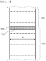
- FIG. 6 is a plan view showing the state in which the standby electrode roll and the moving electrode roll are connected to each other.
- FIG. 6 the state in which the tape 640 is attached to the electrode roll connection portion 150 at which the moving electrode roll 120 and the standby electrode roll 110 are connected to each other, whereby the two electrode rolls are connected to each other, is shown.
- the standby electrode roll 110 Since the edge of the standby electrode roll 110 is cut by the moving cutter, which moves along the slit formed in the first connection unit, the standby electrode roll may be cut in parallel to a width direction a of the electrode roll.
- the line along which the ends of the standby electrode roll and the moving electrode roll join each other at the electrode roll connection portion 150 may be straight. Consequently, overlapping between both electrodes at the electrode roll connection portion 150 may be minimized, whereby it is possible to prevent occurrence of a difference in thickness at the electrode roll connection portion 150.
- the electrode connection apparatus according to the present invention and the electrode connection automation method using the electrode connection apparatus are used, as described above, it is possible to automatically connect the standby electrode roll and the moving electrode roll to each other. Consequently, it is not necessary to suspend the process in order to connect the electrode rolls to each other, and the electrode roll connection portion may be uniformly formed, whereby it is possible to improve productivity in an electrode manufacturing process.
- an electrode connection apparatus includes a transfer unit and a leading unit. Even though a start portion of a standby electrode roll and an end portion of a moving electrode roll do not face each other in parallel with each other, therefore, it is possible to automatically connect the electrode rolls to each other.
- a tape is attached to only one surface of each of the standby electrode roll and the moving electrode roll, whereby it is possible to simplify a connection process, and therefore it is possible to improve productivity.
Landscapes
- Engineering & Computer Science (AREA)
- Manufacturing & Machinery (AREA)
- Chemical & Material Sciences (AREA)
- Chemical Kinetics & Catalysis (AREA)
- Electrochemistry (AREA)
- General Chemical & Material Sciences (AREA)
- Replacement Of Web Rolls (AREA)
Abstract
Description
- This application claims the benefit of priority to
Korean Patent Application No. 2020-0087016 filed on July 14, 2020 - The present invention relates to an electrode connection apparatus and an electrode connection automation method using the same, and more particularly to an electrode connection apparatus capable of automatically connecting a new standby electrode roll to an end of a moving electrode roll during an electrode manufacturing process performed as a roll-to-roll process and an electrode connection automation method using the same.
- A lithium secondary battery, which is capable of being charged and discharged, has been widely used as an energy source for wireless mobile devices or wearable devices, which are worn on bodies, and has also been used as an energy source for electric vehicles and hybrid electric vehicles presented as alternatives to existing gasoline and diesel vehicles, which cause air pollution.
- In the lithium secondary battery, a positive electrode and a negative electrode are stacked in the state in which a separator is interposed therebetween, and lithium ions move between the positive electrode and the negative electrode, whereby the lithium secondary battery is repeatedly charged and discharged.
- A process of manufacturing an electrode including the positive electrode and the negative electrode includes a step of coating the remaining part of an electrode sheet wound in the form of a roll, excluding parts at which electrode tabs are to be formed, with an electrode agent, a step of drying and rolling the electrode agent, a step of slitting the electrode sheet, and a step of notching the slit electrode sheet into unit electrodes.
- An electrode manufacturing process is performed as a roll-to-roll continuous process. In the case in which an electrode roll wound in the form of a roll is completely consumed while electrodes are continuously manufactured using the electrode roll, a worker stops equipment, connects an edge of the electrode roll that is being used and an edge of a new electrode roll to each other using a tape, and reoperates the equipment.
- In the case in which an electrode production process is suspended in order to replace the electrode roll and then the electrode production process is resumed, as described above, productivity is reduced.
- In connection therewith, Patent Document 1 discloses an electrode production system for secondary batteries capable of connecting a first electrode material mounted to a first electrode material supply reel and a second electrode material mounted to a second electrode material supply reel to each other in order to perform a continuous process, but does not concretely disclose a method of automatically attaching a tape to the first electrode material and the second electrode material using a tape suction plate.
- Patent Document 2 relates an automatic electrode film replacement apparatus configured such that, when an electrode film wound in the form of a roll is almost completely consumed during a process of continuously transferring the electrode film to manufacture a secondary battery, an edge of the electrode film that is being used and an edge of a new electrode film are automatically connected to each other by joining, whereby the secondary battery manufacturing process is continuously performed without interruption.
- Patent Document 2 is capable of realizing joint connection when the electrode film that is being used and the new electrode film are moved and disposed so as to face each other, but does not disclose an apparatus capable of transferring the new electrode film to the electrode film that is being used and disposing the new electrode film when the electrode film that is being used is not disposed so as to face the new electrode film.
- Therefore, there is a high necessity for technology capable of automatically connecting electrode rolls to each other without intervention of a worker even in the case in which the electrode rolls are not disposed so as to face each other when a continuous electrode manufacturing process is performed, whereby uniform electrode connection quality is achieved irrespective of skill of the worker.
-
- (Patent Document 1)
Korean Registered Patent Publication No. 1857396 - (Patent Document 2)
Korean Patent Application Publication No. 2016-0133264 (2016.11.22 - The present invention has been made in view of the above problems, and it is an object of the present invention to provide an electrode connection apparatus capable of continuously supplying an electrode roll without interruption during an electrode manufacturing process, whereby it is possible to improve productivity and to prevent occurrence of defects during an electrode roll connection process, and an electrode connection automation method using the same.
- In order to accomplish the above object, an electrode connection apparatus according to the present invention includes a transfer unit configured to transfer a start portion of a standby electrode roll while gripping the start portion, a leading unit configured to move upwards while gripping the start portion of the standby electrode roll transferred by the transfer unit, a first connection unit configured to fix the standby electrode roll transferred by the leading unit thereto, a second connection unit configured to fix an end portion of a moving electrode roll thereto, and a taping unit configured to connect the standby electrode roll and the moving electrode roll to each other.
- In the electrode connection apparatus according to the present invention, the transfer unit may be configured to have a structure capable of moving toward the standby electrode roll in a first direction and moving in a second direction opposite the first direction while griping opposite side edges of the start portion of the standby electrode roll.
- In the electrode connection apparatus according to the present invention, the leading unit may be configured to move downwards, may be configured to grip an edge of the start portion of the standby electrode roll, and may be configured to move upwards.
- In the electrode connection apparatus according to the present invention, the first connection unit may be configured to fix the start portion of the standby electrode roll thereto by suctioning.
- In the electrode connection apparatus according to the present invention, the first connection unit may include a moving cutter configured to cut the standby electrode roll.
- In the electrode connection apparatus according to the present invention, the standby electrode roll may be fixed to a first surface of the first connection unit, the moving cutter may be disposed at a second surface, which is an outer surface opposite the first surface, and the first connection unit may have a slit such that when the moving cutter moves along the slit, the moving cutter cuts the standby electrode roll.
- In the electrode connection apparatus according to the present invention, the first connection unit may be configured to have a structure in which the first connection unit moves toward the second connection unit such that an edge of the start portion of the standby electrode roll abuts the end portion of the moving electrode roll fixed to the second connection unit.
- In the electrode connection apparatus according to the present invention, the end portion of the moving electrode roll may be fixed to a second surface of the second connection unit, and the taping unit may be disposed outside a first surface, the first surface being an outer surface opposite the second surface.
- In the electrode connection apparatus according to the present invention, the second connection unit may have a penetrated portion configured to receive a tape of the taping unit passing therethrough.
- In the electrode connection apparatus according to the present invention, the taping unit may include a supply portion configured to supply a tape, a tape gripper configured to transfer the tape supplied by the supply portion to an attachment portion, and the attachment portion being configured to move to an electrode roll connection portion while fixing the tape, and the tape gripper may have a tape cutter configured to cut the tape.
- In addition, the present invention provides an electrode connection automation method using the electrode connection apparatus, the electrode connection automation method including (a) transferring the start portion of the standby electrode roll while gripping the start portion, (b) moving the leading unit downwards, gripping the start portion of the standby electrode roll, and transferring the start portion of the standby electrode roll to the first connection unit, (c) cutting the start portion of the standby electrode roll, and (d) connecting the standby electrode roll and a moving electrode roll to each other.
- The electrode connection automation method according to the present invention may include moving the standby electrode roll in a direction toward the moving electrode roll after step (c).
- In the electrode connection automation method according to the present invention, step (d) may include mounting a tape to the attachment portion of the taping unit and attaching the tape to a connection portion at which the start portion of the standby electrode roll and the end portion of the moving electrode roll are connected to each other.
- As is apparent from the above description, an electrode connection apparatus according to the present invention includes a transfer unit and a leading unit. Even though a start portion of a standby electrode roll and an end portion of a moving electrode roll do not face each other in parallel with each other, therefore, it is possible to automatically connect the electrode rolls to each other.
- Also, in the case in which the electrode connection apparatus according to the present invention is used, a tape is attached to only one surface of each of the standby electrode roll and the moving electrode roll, whereby it is possible to simplify a connection process, and therefore it is possible to improve productivity.
-
-
FIG. 1 is a perspective view of an electrode connection apparatus according to the present invention. -
FIG. 2 is a perspective view showing a process of transferring a standby electrode roll using a transfer unit and a leading unit ofFIG. 1 . -
FIG. 3 is a perspective view showing a process of cutting the standby electrode roll using a first connection unit ofFIG. 1 . -
FIG. 4 is a perspective view showing movement of the standby electrode roll cut inFIG. 3 to a second connection unit ofFIG. 1 . -
FIG. 5 is a perspective view showing a process of attaching a tape to an electrode roll connection portion. -
FIG. 6 is a plan view showing the state in which the standby electrode roll and a moving electrode roll are connected to each other. - Now, preferred embodiments of the present invention will be described in detail with reference to the accompanying drawings such that the preferred embodiments of the present invention can be easily implemented by a person having ordinary skill in the art to which the present invention pertains. In describing the principle of operation of the preferred embodiments of the present invention in detail, however, a detailed description of known functions and configurations incorporated herein will be omitted when the same may obscure the subject matter of the present invention.
- In addition, the same reference numbers will be used throughout the drawings to refer to parts that perform similar functions or operations. In the case in which one part is said to be connected to another part throughout the specification, not only may the one part be directly connected to the other part, but also, the one part may be indirectly connected to the other part via a further part. In addition, that a certain element is included does not mean that other elements are excluded, but means that such elements may be further included unless mentioned otherwise.
- In addition, a description to embody elements through limitation or addition may be applied to all inventions, unless particularly restricted, and does not limit a specific invention.
- Also, in the description of the invention and the claims of the present application, singular forms are intended to include plural forms unless mentioned otherwise.
- Also, in the description of the invention and the claims of the present application, "or" includes "and" unless mentioned otherwise. Therefore, "including A or B" means three cases, namely, the case including A, the case including B, and the case including A and B.
- In addition, all numeric ranges include the lowest value, the highest value, and all intermediate values therebetween unless the context clearly indicates otherwise.
- Embodiments of the present invention will be described in detail with reference to the accompanying drawings.
-
FIG. 1 is a perspective view of an electrode connection apparatus according to the present invention. - Referring to
FIG. 1 , the electrode connection apparatus according to the present invention includes atransfer unit 200 configured to transfer astart portion 111 of a standby electrode roll in a state of gripping the start portion, a leadingunit 300 configured to move upwards in a state of gripping thestart portion 111 of the standby electrode roll transferred by thetransfer unit 200, afirst connection unit 400 configured to fix thestandby electrode roll 110 transferred by the leadingunit 300, and asecond connection unit 500 configured to fix an end portion of a movingelectrode roll 120. - An electrode connection automation method using the electrode connection apparatus includes (a) a step of transferring a
start portion 111 of a standby electrode roll in a state of gripping the start portion, (b) a step of the leadingunit 300 moving downwards to grip thestart portion 111 of the standby electrode roll and transferring thestart portion 111 of the standby electrode roll to thefirst connection unit 400, (c) a step of cutting thestart portion 111 of the standby electrode roll, and (d) a step of connecting thestandby electrode roll 110 and a movingelectrode roll 120 to each other. - In addition, a process of moving the
standby electrode roll 110 in a direction toward the movingelectrode roll 120 after step (c) may be included, and step (d) may include a process of mounting a tape to an attachment portion of a taping unit and a process of attaching the tape to a connection portion at which the start portion of the standby electrode roll and an end portion of the moving electrode roll are connected to each other. - The
transfer unit 200, the leadingunit 300, thefirst connection unit 400, and thesecond connection unit 500 shown inFIG. 1 constitute an embodiment. The structures of the units are not limited to structures shown in this specification as long as the units are capable of performing functions that will be described below. - In a concrete example, the
transfer unit 200 includes twotransfer grippers 210. Thetransfer grippers 210 are disposed spaced apart from each other so as to grip opposite side edges of the standby electrode roll in a moving direction thereof. In addition, thetransfer grippers 210 move toward thestandby electrode roll 110, grip thestandby electrode roll 110, and transfer the standby electrode roll in a direction toward the leading unit within a predetermined section in a state of being mounted to thetransfer unit 200. - The
transfer unit 200 moves toward thestandby electrode roll 110 in a first direction, which is an x+ direction, and grips the opposite side edges of thestart portion 111 of the standby electrode roll using thetransfer grippers 210. When the transfer unit moves in a second direction, which is an x- direction, in this state, thestandby electrode roll 110 is withdrawn. -
FIG. 2 is a perspective view showing a process of transferring the standby electrode roll using the transfer unit and the leading unit ofFIG. 1 . - Referring to
FIG. 2 , when thetransfer unit 200 moves in the x- direction in the state in which thetransfer grippers 210 of the transfer unit grip the opposite side edges of thestart portion 111 of thestandby electrode roll 110, thestandby electrode roll 110 is withdrawn. - When the
start portion 111 of the standby electrode roll reaches under the leadingunit 300, thetransfer grippers 210 are rotated in a direction indicated by an arrow such that an edge of thestart portion 111 of the standby electrode roll faces the leadingunit 300. Even though the leadingunit 300 moves only in an upward-downward direction, therefore, a process of the leadingunit 300 gripping thestart portion 111 of the standby electrode roll may be easily performed. - In order for the leading
unit 300 to grip thestart portion 111 of the standby electrode roll, the length of alength adjustment portion 320 of the leadingunit 300 is increased, whereby a leadinggripper 310 may grip thestart portion 111 of the standby electrode roll, the edge of which is bent upwards. When the length of thelength adjustment portion 320 is decreased in the state in which the leadinggripper 310 grips the edge of thestart portion 111 of the standby electrode roll, thestart portion 111 of the standby electrode roll may be moved upwards. -
FIG. 3 is a perspective view showing a process of cutting the standby electrode roll using the first connection unit ofFIG. 1 . - Referring to
FIG. 3 , thestart portion 111 of the standby electrode roll moved upwards by the leadingunit 300 is fixed to afirst surface 401 of thefirst connection unit 400. - The
first surface 401 may be configured as a suction portion. For example, a vacuum hole may be formed in asecond surface 402, and a vacuum decompression cylinder may be coupled to thefirst connection unit 400. Consequently, thestandby electrode roll 110 may be fixed to thefirst surface 401 by suctioning of the suction portion. - The
first connection unit 400 may be provided with a movingcutter 420 configured to cut thestandby electrode roll 110. The cutting position of thestandby electrode roll 110 may be set in consideration of the position of the electrode roll connection portion at which thestandby electrode roll 110 and the movingelectrode roll 120 are connected to each other, and then cutting may be performed by the movingcutter 420. - The standby electrode roll is fixed to the
first surface 401 of thefirst connection unit 400, and the movingcutter 420 is disposed at asecond surface 402, which is an outer surface opposite thefirst surface 401. The movingcutter 420 is disposed such that a part of aknife edge 421 protrudes outwards from one side edge portion of thefirst surface 401. In this state, the movingcutter 420 cuts thestandby electrode roll 110 while moving to the other side edge portion of thefirst surface 401. Aslit 410 is formed in thefirst connection unit 400 such that the movingcutter 420 can be moved as described above. - A
residual electrode 112 formed as the result of cutting performed by the movingcutter 420 is removed. -
FIG. 4 is a perspective view showing movement of the standby electrode roll cut inFIG. 3 to the second connection unit ofFIG. 1 . - Referring to
FIG. 4 , anend portion 121 of the movingelectrode roll 120 is fixed to asecond surface 502 of thesecond connection unit 500, and ataping unit 600 is disposed outside afirst surface 501, which is an outer surface opposite thesecond surface 502. - The
second surface 502 of thesecond connection unit 500 may be configured as a suction portion. For example, a vacuum hole may be formed in thesecond surface 502, and a vacuum decompression cylinder may be coupled to thesecond connection unit 500. Consequently, the movingelectrode roll 120 may be fixed to thesecond surface 502 by suctioning of the suction portion. - The
first connection unit 400 moves toward thesecond connection unit 500 such that the edge of thestart portion 111 of the standby electrode roll abuts theend portion 121 of the movingelectrode roll 120. - The
standby electrode roll 110 is attached to thesecond surface 502 of thesecond connection unit 500 such that thestart portion 111 of the standby electrode roll and theend portion 121 of the movingelectrode roll 120 come into contact with each other. At this time, air suctioning performed by the suction portion of thefirst connection unit 400 to suction thestandby electrode roll 110 is interrupted, and thesecond connection unit 500 starts to suction thestandby electrode roll 110, whereby thestandby electrode roll 110 is fixed to thesecond surface 502 of thesecond connection unit 500. - A tape is attached to the electrode roll connection portion at which the standby electrode roll attached to the
second surface 501 of thesecond connection unit 500 and the moving electrode roll join each other using thetaping unit 600 disposed outside thefirst surface 501 of thesecond connection unit 500. Thesecond connection unit 500 is provided with a penetratedportion 510, through which the tape of thetaping unit 600 passes. -
FIG. 5 is a perspective view showing a process of attaching a tape to the electrode roll connection portion. - Referring to
FIG. 5 together withFIG. 4 , thetaping unit 600 includes asupply portion 610 configured to supply a tape, atape gripper 620 configured to withdraw the tape supplied by thesupply portion 610 in a state of gripping the tape such that the tape is disposed at the outer surface of anattachment portion 630, and theattachment portion 630 configured to move to the electrode roll connection portion in a state of fixing the tape. In addition, thetape gripper 620 is provided with a tape cutter (not shown) configured to cut the tape. - The
tape gripper 620 grips an edge of a tape roll, and disposes the tape such that a non-adhesive surface of the tape is located at the outer surface of theattachment portion 630. At this time, the attachment portion fixes the non-adhesive surface of the tape by suctioning. Suctioning of the attachment portion may be performed in the same manner as the suction portion of each of the first connection unit and the second connection unit. A vacuum decompression suctioning method may be used. - The
tape gripper 620 returns to the position before the tape is transferred, and the tape withdrawn from the tape roll is cut in a state of being gripped. At this time, the tape is cut to a length necessary to be attached to the electrode roll connection portion, and is attached to theattachment portion 630. - The
attachment portion 630 is movable by a transfer means, and may pass through the penetratedportion 510 formed in thesecond connection unit 500 in order to attach the tape to the electrode roll connection portion. -
FIG. 6 is a plan view showing the state in which the standby electrode roll and the moving electrode roll are connected to each other. - Referring to
FIG. 6 , the state in which thetape 640 is attached to the electroderoll connection portion 150 at which the movingelectrode roll 120 and thestandby electrode roll 110 are connected to each other, whereby the two electrode rolls are connected to each other, is shown. - Since the edge of the
standby electrode roll 110 is cut by the moving cutter, which moves along the slit formed in the first connection unit, the standby electrode roll may be cut in parallel to a width direction a of the electrode roll. - As a result, the line along which the ends of the standby electrode roll and the moving electrode roll join each other at the electrode
roll connection portion 150 may be straight. Consequently, overlapping between both electrodes at the electroderoll connection portion 150 may be minimized, whereby it is possible to prevent occurrence of a difference in thickness at the electroderoll connection portion 150. - In the case in which the electrode connection apparatus according to the present invention and the electrode connection automation method using the electrode connection apparatus are used, as described above, it is possible to automatically connect the standby electrode roll and the moving electrode roll to each other. Consequently, it is not necessary to suspend the process in order to connect the electrode rolls to each other, and the electrode roll connection portion may be uniformly formed, whereby it is possible to improve productivity in an electrode manufacturing process.
- Those skilled in the art to which the present invention pertains will appreciate that various applications and modifications are possible within the category of the present invention based on the above description.
-
- 110:
- Standby electrode roll
- 111:
- Start portion of standby electrode roll
- 112:
- Residual electrode
- 120:
- Moving electrode roll
- 121:
- End portion of moving electrode roll
- 150:
- Electrode roll connection portion
- 200:
- Transfer unit
- 210:
- Transfer gripper
- 300:
- Leading unit
- 310:
- Leading gripper
- 320:
- Length adjustment portion
- 400:
- First connection unit
- 401:
- First surface
- 402:
- Second surface
- 410:
- Slit
- 420:
- Moving cutter
- 421:
- Knife edge
- 500:
- Second connection unit
- 501:
- First surface
- 502:
- Second surface
- 510:
- Penetrated portion
- 600:
- Taping unit
- 610:
- Supply portion
- 620:
- Tape gripper
- 630:
- Attachment portion
- 640:
- Tape
- As is apparent from the above description, an electrode connection apparatus according to the present invention includes a transfer unit and a leading unit. Even though a start portion of a standby electrode roll and an end portion of a moving electrode roll do not face each other in parallel with each other, therefore, it is possible to automatically connect the electrode rolls to each other.
- Also, in the case in which the electrode connection apparatus according to the present invention is used, a tape is attached to only one surface of each of the standby electrode roll and the moving electrode roll, whereby it is possible to simplify a connection process, and therefore it is possible to improve productivity.
Claims (13)
- An electrode connection apparatus comprising:a transfer unit (200) configured to transfer a start portion (111) of a standby electrode roll while gripping the start portion;a leading unit (300) configured to move upwards while gripping the start portion (111) of the standby electrode roll transferred by the transfer unit;a first connection unit (400) configured to fix the standby electrode roll (110) transferred by the leading unit (300) thereto;a second connection unit (500) configured to fix an end portion (121) of a moving electrode roll thereto; anda taping unit (600) configured to connect the standby electrode roll (110) and the moving electrode roll (120) to each other.
- The electrode connection apparatus according to claim 1, wherein the transfer unit (200) is configured to have a structure capable of moving toward the standby electrode roll (110) in a first direction and moving in a second direction opposite the first direction while gripping opposite side edges of the start portion (111) of the standby electrode roll.
- The electrode connection apparatus according to claim 1, wherein the leading unit (300) is configured to move downwards, grip an edge of the start portion (111) of the standby electrode roll, and move upwards.
- The electrode connection apparatus according to claim 1, wherein the first connection unit (400) is configured to fix the start portion (111) of the standby electrode roll thereto by suctioning.
- The electrode connection apparatus according to claim 1, wherein the first connection unit (400) comprises a moving cutter (420) configured to cut the standby electrode roll (110).
- The electrode connection apparatus according to claim 5, whereinthe standby electrode roll (110) is fixed to a first surface (401) of the first connection unit (400),the moving cutter (420) is disposed at a second surface (402), which is an outer surface opposite the first surface (401), andthe first connection unit has a slit (410) such that when the moving cutter (420) moves along the slit, the moving cutter (420) cuts the standby electrode roll (110) .
- The electrode connection apparatus according to claim 1, wherein the first connection unit (400) is configured to have a structure in which the first connection unit moves toward the second connection unit (500) such that an edge of the start portion (111) of the standby electrode roll abuts the end portion (121) of the moving electrode roll fixed to the second connection unit (500).
- The electrode connection apparatus according to claim 1, whereinthe end portion (121) of the moving electrode roll is fixed to a second surface (502) of the second connection unit (500), andthe taping unit (600) is disposed outside a first surface (501), the first surface (501) being an outer surface opposite the second surface (502).
- The electrode connection apparatus according to claim 8, wherein the second connection unit (500) has a penetrated portion (510) configured to receive a tape of the taping unit (600) passing therethrough.
- The electrode connection apparatus according to claim 1, wherein
the taping unit (600) comprises:a supply portion (610) configured to supply a tape;a tape gripper (620) configured to transfer the tape supplied by the supply portion to an attachment portion (630); andthe attachment portion (630) being configured to move to an electrode roll connection portion while fixing the tape, andthe tape gripper (620) has a tape cutter configured to cut the tape. - An electrode connection automation method using the electrode connection apparatus according to any one of claims 1 to 10, the electrode connection automation method comprising:(a) transferring the start portion (111) of the standby electrode roll while gripping the start portion;(b) moving the leading unit (300) downwards, gripping the start portion (111) of the standby electrode roll, and transferring the start portion (111) of the standby electrode roll to the first connection unit (400);(c) cutting the start portion (111) of the standby electrode roll; and(d) connecting the standby electrode roll (110) and a moving electrode roll (120) to each other.
- The electrode connection automation method according to claim 11, comprising, after step (c), moving the standby electrode roll (110) in a direction toward the moving electrode roll (120).
- The electrode connection automation method according to claim 11, wherein step (d) comprises:mounting a tape (640) to the attachment portion (630) of the taping unit (600); andattaching the tape (640) to a connection portion at which the start portion (111) of the standby electrode roll and the end portion (121) of the moving electrode roll are connected to each other.
Applications Claiming Priority (2)
| Application Number | Priority Date | Filing Date | Title |
|---|---|---|---|
| KR1020200087016A KR20220008631A (en) | 2020-07-14 | 2020-07-14 | Electrode Connection Device and Automatic Method for Electrode Connection Using the Same |
| PCT/KR2021/008580 WO2022014934A1 (en) | 2020-07-14 | 2021-07-06 | Electrode connection device and automated electrode connection method using same |
Publications (3)
| Publication Number | Publication Date |
|---|---|
| EP4112516A1 true EP4112516A1 (en) | 2023-01-04 |
| EP4112516A4 EP4112516A4 (en) | 2024-04-10 |
| EP4112516B1 EP4112516B1 (en) | 2025-04-16 |
Family
ID=79554907
Family Applications (1)
| Application Number | Title | Priority Date | Filing Date |
|---|---|---|---|
| EP21842468.7A Active EP4112516B1 (en) | 2020-07-14 | 2021-07-06 | Electrode connection apparatus and electrode connection automation method using the same |
Country Status (7)
| Country | Link |
|---|---|
| US (1) | US12583700B2 (en) |
| EP (1) | EP4112516B1 (en) |
| KR (2) | KR20220008631A (en) |
| CN (1) | CN115135591B (en) |
| ES (1) | ES3026461T3 (en) |
| HU (1) | HUE071099T2 (en) |
| WO (1) | WO2022014934A1 (en) |
Families Citing this family (4)
| Publication number | Priority date | Publication date | Assignee | Title |
|---|---|---|---|---|
| KR102868979B1 (en) * | 2023-03-02 | 2025-10-14 | (주) 피토 | A method and system of producing jelly roll |
| IT202300022593A1 (en) * | 2023-10-27 | 2025-04-27 | Manz Italy Srl | TRANSFER APPARATUS FOR COILS, MACHINE COMPRISING THE TRANSFER APPARATUS AND METHOD FOR MANUFACTURING ELECTRIC ENERGY STORAGE DEVICES |
| WO2025204122A1 (en) * | 2024-03-25 | 2025-10-02 | コマツNtc株式会社 | Winding machine, method for connecting electrode material, tab molding machine, method for recovering electrode material, method for manufacturing electrode material, and method for manufacturing electrode body |
| KR20260009095A (en) * | 2024-07-10 | 2026-01-19 | 엘지전자 주식회사 | winder |
Family Cites Families (37)
| Publication number | Priority date | Publication date | Assignee | Title |
|---|---|---|---|---|
| US3440126A (en) * | 1966-02-28 | 1969-04-22 | Eastman Kodak Co | Web splicer |
| US4157934A (en) * | 1977-07-18 | 1979-06-12 | Compensating Tension Controls, Inc. | Low tension lap slicer unit |
| JPS63165258A (en) * | 1986-12-25 | 1988-07-08 | Tokyo Jido Kikai Seisakusho:Kk | Automatic connecting device for band like material |
| JP2624492B2 (en) * | 1987-12-17 | 1997-06-25 | 富士写真フイルム 株式会社 | Web Butt Joiner |
| US5064488A (en) * | 1990-03-27 | 1991-11-12 | Trine Manufacturing Company, Inc. | Apparatus and method for splicing film |
| DE4016578A1 (en) * | 1990-05-23 | 1991-11-28 | Winkler Duennebier Kg Masch | DEVICE FOR JOINING MATERIAL RAILS |
| US5881964A (en) * | 1996-05-24 | 1999-03-16 | Fuji Photo Film Co., Ltd. | Web splicing apparatus having offset splicing and taping |
| JP2001233514A (en) * | 2000-02-23 | 2001-08-28 | Shikoku Kakoki Co Ltd | Device and method for splicing roll film |
| IT1321284B1 (en) | 2000-06-05 | 2004-01-08 | Gd Spa | DEVICE FOR THE AUTOMATIC JOINTING OF TAPES CARRIED OUT BY REELS. |
| DE10057597A1 (en) * | 2000-11-21 | 2002-05-23 | Kolbus Gmbh & Co Kg | Device for storing and unrolling of continuous material for use in book-binding machines etc., in which rolls are stored in a shaft lined with rollers, so that as a roll unwinds it is drawn forward leaving space for the next roll |
| JP4406593B2 (en) | 2004-10-06 | 2010-01-27 | 新日本工機株式会社 | Film bonding equipment |
| US6978816B1 (en) * | 2004-12-17 | 2005-12-27 | The Procter & Gamble Company | Method and apparatus for splicing a web material |
| JP2008127093A (en) * | 2006-11-24 | 2008-06-05 | Ishida Co Ltd | Film supply apparatus and packaging apparatus provided with the same |
| KR100819183B1 (en) | 2007-10-19 | 2008-04-03 | 주식회사 코엠 | Jointing device and method for attaching tape to both sides of lithium ion battery electrode plate |
| KR101070283B1 (en) * | 2009-12-09 | 2011-10-06 | 수미토모 케미칼 컴퍼니 리미티드 | System for manufacturing optical display device and method for manufacturing the optical display device |
| JP5996204B2 (en) * | 2012-02-13 | 2016-09-21 | 日産自動車株式会社 | Belt-shaped battery material transport device and transport method |
| KR102108498B1 (en) | 2012-05-23 | 2020-05-08 | 가부시키가이샤 니콘 | Substrate processing system |
| KR101479723B1 (en) | 2012-07-06 | 2015-01-08 | 유일에너테크(주) | System for producing electrodes of battery and feeding apparatus used for the system |
| ITTO20120683A1 (en) * | 2012-07-31 | 2014-02-01 | Sidel Spa Con Socio Unico | DEVICE AND METHOD FOR THE JOINT OF RIBBONS PROVIDED WITH REPEATED DECORATIONS |
| KR101479724B1 (en) | 2013-11-25 | 2015-01-08 | 유일에너테크(주) | System for producing electrodes of battery |
| DE102014108461A1 (en) * | 2014-06-16 | 2015-12-17 | Leonhard Kurz Stiftung & Co. Kg | Method and device for joining film webs |
| CN106660726B (en) * | 2014-06-30 | 2018-11-02 | 株式会社瑞光 | Sheet body transmitting system and for the sheet body transmitting system sheet body send out method |
| US9981821B2 (en) * | 2015-02-19 | 2018-05-29 | Tecnau S.R.L. | Splicing equipment for strips wound on a pair of spools |
| KR101695650B1 (en) | 2015-05-12 | 2017-01-12 | 주식회사 디에이테크놀로지 | Apparatus for Automatically Changing Electrode Films |
| KR102136524B1 (en) * | 2016-10-20 | 2020-07-22 | 주식회사 엘지화학 | Apparatus for connecting film |
| KR102474343B1 (en) | 2016-12-14 | 2022-12-05 | 현대자동차 주식회사 | Auto splicing device of roll to roll feeding system |
| KR101873197B1 (en) * | 2016-12-15 | 2018-07-02 | (주)피토 | Apparatus For Connecting Meterial Of Rechargeable Battery |
| KR101827204B1 (en) * | 2017-03-13 | 2018-02-07 | 주식회사 신한정공 | Apparatus for unwinding and supplying sheet from sheet-roll |
| KR101857396B1 (en) | 2017-09-29 | 2018-05-11 | 정연길 | System for producing electrodes of battery |
| CN108598547B (en) * | 2018-04-27 | 2024-03-19 | 深圳市诚捷智能装备股份有限公司 | Battery making machine |
| KR102341464B1 (en) * | 2018-05-04 | 2021-12-22 | 주식회사 엘지에너지솔루션 | Cutting device and method for electrode sheet |
| KR102538070B1 (en) * | 2018-11-30 | 2023-05-30 | 엘지전자 주식회사 | Electrode roll feeder |
| KR102330790B1 (en) | 2019-01-10 | 2021-11-24 | 나영혜 | Method for providing lbs based placing order placement processing service using chatting agent and chatbot |
| CN209853423U (en) * | 2019-03-12 | 2019-12-27 | 宁德时代新能源科技股份有限公司 | Unwinding device and unwinding equipment |
| KR102043024B1 (en) * | 2019-05-29 | 2019-11-12 | 주식회사 우원기술 | Splicing Device of Secondary Battery Electrode Film |
| KR102120098B1 (en) | 2020-01-03 | 2020-06-08 | 세종기술 주식회사 | Tape Continuous Feeding Apparatus and Method for Continuous Feeding of Tape |
| KR102390172B1 (en) | 2020-06-03 | 2022-04-25 | 주식회사 탑 엔지니어링 | Connecting apparatus and connecting method using ths same |
-
2020
- 2020-07-14 KR KR1020200087016A patent/KR20220008631A/en not_active Ceased
-
2021
- 2021-07-06 EP EP21842468.7A patent/EP4112516B1/en active Active
- 2021-07-06 ES ES21842468T patent/ES3026461T3/en active Active
- 2021-07-06 HU HUE21842468A patent/HUE071099T2/en unknown
- 2021-07-06 US US17/915,000 patent/US12583700B2/en active Active
- 2021-07-06 WO PCT/KR2021/008580 patent/WO2022014934A1/en not_active Ceased
- 2021-07-06 CN CN202180014517.4A patent/CN115135591B/en active Active
-
2024
- 2024-08-20 KR KR1020240111093A patent/KR102861922B1/en active Active
Also Published As
| Publication number | Publication date |
|---|---|
| US20230150784A1 (en) | 2023-05-18 |
| EP4112516A4 (en) | 2024-04-10 |
| CN115135591B (en) | 2025-08-05 |
| ES3026461T3 (en) | 2025-06-11 |
| WO2022014934A1 (en) | 2022-01-20 |
| US12583700B2 (en) | 2026-03-24 |
| KR20240131295A (en) | 2024-08-30 |
| EP4112516B1 (en) | 2025-04-16 |
| KR20220008631A (en) | 2022-01-21 |
| HUE071099T2 (en) | 2025-07-28 |
| KR102861922B1 (en) | 2025-09-22 |
| CN115135591A (en) | 2022-09-30 |
Similar Documents
| Publication | Publication Date | Title |
|---|---|---|
| EP4112516B1 (en) | Electrode connection apparatus and electrode connection automation method using the same | |
| EP2879223B1 (en) | Stack apparatus and stack method of unit for secondary battery | |
| EP3813172B1 (en) | Automatic replacement device of secondary battery material | |
| EP3865434B1 (en) | Continuous tape-feeding apparatus and continuous tape-feeding method | |
| CN110870110B (en) | Device and method for notching electrode plate | |
| CN115103745B (en) | Box electrode cutting equipment | |
| EP4108613A1 (en) | Tape removal device | |
| CN223181178U (en) | Lamination unit processing device and lamination equipment | |
| EP4105154A1 (en) | Automated electrode roll connection device | |
| KR20220127157A (en) | Apparatus and method for continuously manufacturing electrode | |
| CN117120353B (en) | Electrode connection membrane winding device, winding method and electrode roll | |
| KR102003712B1 (en) | Electrode Tab-Feeding Device Comprising Guide for Positioning Electrode Tab at Correct Point | |
| KR102611154B1 (en) | electrode sheet connection method for secondary battery | |
| CN115151500B (en) | Tape application equipment | |
| CN117001164B (en) | A device for cutting electrode plates for energy storage devices based on multi-channel lasers | |
| CN117546324A (en) | Electrode cutting device and battery cell manufacturing apparatus including the same | |
| KR102962578B1 (en) | Electrode manufacturing device and electrode manufacturing method using the same | |
| EP4550512A1 (en) | Method for manufacturing electrode assembly with improved processability, and electrode assembly manufactured using same | |
| KR102739372B1 (en) | Automatic taping connection device for electrode separator end | |
| CN115380396B (en) | Electrode forming device with slotted positioning pins and electrode forming method using the same | |
| KR20140130929A (en) | Guide roller apparatus of secondary battery | |
| WO2025244239A1 (en) | Notching tab scrap suction apparatus | |
| KR20220102118A (en) | Electrode manufacturing device and electrode manufacturing method using the same |
Legal Events
| Date | Code | Title | Description |
|---|---|---|---|
| STAA | Information on the status of an ep patent application or granted ep patent |
Free format text: STATUS: THE INTERNATIONAL PUBLICATION HAS BEEN MADE |
|
| PUAI | Public reference made under article 153(3) epc to a published international application that has entered the european phase |
Free format text: ORIGINAL CODE: 0009012 |
|
| STAA | Information on the status of an ep patent application or granted ep patent |
Free format text: STATUS: REQUEST FOR EXAMINATION WAS MADE |
|
| 17P | Request for examination filed |
Effective date: 20220928 |
|
| AK | Designated contracting states |
Kind code of ref document: A1 Designated state(s): AL AT BE BG CH CY CZ DE DK EE ES FI FR GB GR HR HU IE IS IT LI LT LU LV MC MK MT NL NO PL PT RO RS SE SI SK SM TR |
|
| DAV | Request for validation of the european patent (deleted) | ||
| DAX | Request for extension of the european patent (deleted) | ||
| A4 | Supplementary search report drawn up and despatched |
Effective date: 20240311 |
|
| RIC1 | Information provided on ipc code assigned before grant |
Ipc: H01M 10/04 20060101ALI20240304BHEP Ipc: B65H 21/00 20060101ALI20240304BHEP Ipc: B65H 19/18 20060101ALI20240304BHEP Ipc: H01M 4/04 20060101ALI20240304BHEP Ipc: B65H 35/00 20060101ALI20240304BHEP Ipc: B65H 20/16 20060101ALI20240304BHEP Ipc: B65H 19/10 20060101AFI20240304BHEP |
|
| GRAP | Despatch of communication of intention to grant a patent |
Free format text: ORIGINAL CODE: EPIDOSNIGR1 |
|
| STAA | Information on the status of an ep patent application or granted ep patent |
Free format text: STATUS: GRANT OF PATENT IS INTENDED |
|
| INTG | Intention to grant announced |
Effective date: 20241114 |
|
| P01 | Opt-out of the competence of the unified patent court (upc) registered |
Free format text: CASE NUMBER: APP_65655/2024 Effective date: 20241212 |
|
| GRAS | Grant fee paid |
Free format text: ORIGINAL CODE: EPIDOSNIGR3 |
|
| GRAA | (expected) grant |
Free format text: ORIGINAL CODE: 0009210 |
|
| STAA | Information on the status of an ep patent application or granted ep patent |
Free format text: STATUS: THE PATENT HAS BEEN GRANTED |
|
| AK | Designated contracting states |
Kind code of ref document: B1 Designated state(s): AL AT BE BG CH CY CZ DE DK EE ES FI FR GB GR HR HU IE IS IT LI LT LU LV MC MK MT NL NO PL PT RO RS SE SI SK SM TR |
|
| REG | Reference to a national code |
Ref country code: GB Ref legal event code: FG4D |
|
| REG | Reference to a national code |
Ref country code: CH Ref legal event code: EP Ref country code: DE Ref legal event code: R096 Ref document number: 602021029360 Country of ref document: DE |
|
| REG | Reference to a national code |
Ref country code: IE Ref legal event code: FG4D |
|
| REG | Reference to a national code |
Ref country code: ES Ref legal event code: FG2A Ref document number: 3026461 Country of ref document: ES Kind code of ref document: T3 Effective date: 20250611 |
|
| PGFP | Annual fee paid to national office [announced via postgrant information from national office to epo] |
Ref country code: GB Payment date: 20250624 Year of fee payment: 5 |
|
| PGFP | Annual fee paid to national office [announced via postgrant information from national office to epo] |
Ref country code: BE Payment date: 20250623 Year of fee payment: 5 |
|
| PGFP | Annual fee paid to national office [announced via postgrant information from national office to epo] |
Ref country code: FR Payment date: 20250624 Year of fee payment: 5 |
|
| REG | Reference to a national code |
Ref country code: HU Ref legal event code: AG4A Ref document number: E071099 Country of ref document: HU |
|
| PGFP | Annual fee paid to national office [announced via postgrant information from national office to epo] |
Ref country code: HU Payment date: 20250721 Year of fee payment: 5 |
|
| REG | Reference to a national code |
Ref country code: NL Ref legal event code: MP Effective date: 20250416 |
|
| PG25 | Lapsed in a contracting state [announced via postgrant information from national office to epo] |
Ref country code: NL Free format text: LAPSE BECAUSE OF FAILURE TO SUBMIT A TRANSLATION OF THE DESCRIPTION OR TO PAY THE FEE WITHIN THE PRESCRIBED TIME-LIMIT Effective date: 20250416 |
|
| REG | Reference to a national code |
Ref country code: AT Ref legal event code: MK05 Ref document number: 1785536 Country of ref document: AT Kind code of ref document: T Effective date: 20250416 |
|
| PG25 | Lapsed in a contracting state [announced via postgrant information from national office to epo] |
Ref country code: FI Free format text: LAPSE BECAUSE OF FAILURE TO SUBMIT A TRANSLATION OF THE DESCRIPTION OR TO PAY THE FEE WITHIN THE PRESCRIBED TIME-LIMIT Effective date: 20250416 Ref country code: PT Free format text: LAPSE BECAUSE OF FAILURE TO SUBMIT A TRANSLATION OF THE DESCRIPTION OR TO PAY THE FEE WITHIN THE PRESCRIBED TIME-LIMIT Effective date: 20250818 |
|
| PGFP | Annual fee paid to national office [announced via postgrant information from national office to epo] |
Ref country code: ES Payment date: 20250822 Year of fee payment: 5 |
|
| PGFP | Annual fee paid to national office [announced via postgrant information from national office to epo] |
Ref country code: DE Payment date: 20250624 Year of fee payment: 5 |
|
| REG | Reference to a national code |
Ref country code: LT Ref legal event code: MG9D |
|
| PG25 | Lapsed in a contracting state [announced via postgrant information from national office to epo] |
Ref country code: NO Free format text: LAPSE BECAUSE OF FAILURE TO SUBMIT A TRANSLATION OF THE DESCRIPTION OR TO PAY THE FEE WITHIN THE PRESCRIBED TIME-LIMIT Effective date: 20250716 Ref country code: GR Free format text: LAPSE BECAUSE OF FAILURE TO SUBMIT A TRANSLATION OF THE DESCRIPTION OR TO PAY THE FEE WITHIN THE PRESCRIBED TIME-LIMIT Effective date: 20250717 |
|
| PG25 | Lapsed in a contracting state [announced via postgrant information from national office to epo] |
Ref country code: PL Free format text: LAPSE BECAUSE OF FAILURE TO SUBMIT A TRANSLATION OF THE DESCRIPTION OR TO PAY THE FEE WITHIN THE PRESCRIBED TIME-LIMIT Effective date: 20250416 |
|
| PG25 | Lapsed in a contracting state [announced via postgrant information from national office to epo] |
Ref country code: BG Free format text: LAPSE BECAUSE OF FAILURE TO SUBMIT A TRANSLATION OF THE DESCRIPTION OR TO PAY THE FEE WITHIN THE PRESCRIBED TIME-LIMIT Effective date: 20250416 |
|
| PG25 | Lapsed in a contracting state [announced via postgrant information from national office to epo] |
Ref country code: HR Free format text: LAPSE BECAUSE OF FAILURE TO SUBMIT A TRANSLATION OF THE DESCRIPTION OR TO PAY THE FEE WITHIN THE PRESCRIBED TIME-LIMIT Effective date: 20250416 |
|
| PG25 | Lapsed in a contracting state [announced via postgrant information from national office to epo] |
Ref country code: AT Free format text: LAPSE BECAUSE OF FAILURE TO SUBMIT A TRANSLATION OF THE DESCRIPTION OR TO PAY THE FEE WITHIN THE PRESCRIBED TIME-LIMIT Effective date: 20250416 |
|
| PG25 | Lapsed in a contracting state [announced via postgrant information from national office to epo] |
Ref country code: RS Free format text: LAPSE BECAUSE OF FAILURE TO SUBMIT A TRANSLATION OF THE DESCRIPTION OR TO PAY THE FEE WITHIN THE PRESCRIBED TIME-LIMIT Effective date: 20250716 |
|
| PG25 | Lapsed in a contracting state [announced via postgrant information from national office to epo] |
Ref country code: IS Free format text: LAPSE BECAUSE OF FAILURE TO SUBMIT A TRANSLATION OF THE DESCRIPTION OR TO PAY THE FEE WITHIN THE PRESCRIBED TIME-LIMIT Effective date: 20250816 |
|
| PG25 | Lapsed in a contracting state [announced via postgrant information from national office to epo] |
Ref country code: LV Free format text: LAPSE BECAUSE OF FAILURE TO SUBMIT A TRANSLATION OF THE DESCRIPTION OR TO PAY THE FEE WITHIN THE PRESCRIBED TIME-LIMIT Effective date: 20250416 |
|
| PG25 | Lapsed in a contracting state [announced via postgrant information from national office to epo] |
Ref country code: DK Free format text: LAPSE BECAUSE OF FAILURE TO SUBMIT A TRANSLATION OF THE DESCRIPTION OR TO PAY THE FEE WITHIN THE PRESCRIBED TIME-LIMIT Effective date: 20250416 Ref country code: SM Free format text: LAPSE BECAUSE OF FAILURE TO SUBMIT A TRANSLATION OF THE DESCRIPTION OR TO PAY THE FEE WITHIN THE PRESCRIBED TIME-LIMIT Effective date: 20250416 |
|
| REG | Reference to a national code |
Ref country code: DE Ref legal event code: R097 Ref document number: 602021029360 Country of ref document: DE |
|
| PG25 | Lapsed in a contracting state [announced via postgrant information from national office to epo] |
Ref country code: CZ Free format text: LAPSE BECAUSE OF FAILURE TO SUBMIT A TRANSLATION OF THE DESCRIPTION OR TO PAY THE FEE WITHIN THE PRESCRIBED TIME-LIMIT Effective date: 20250416 |
|
| PG25 | Lapsed in a contracting state [announced via postgrant information from national office to epo] |
Ref country code: EE Free format text: LAPSE BECAUSE OF FAILURE TO SUBMIT A TRANSLATION OF THE DESCRIPTION OR TO PAY THE FEE WITHIN THE PRESCRIBED TIME-LIMIT Effective date: 20250416 |
|
| PG25 | Lapsed in a contracting state [announced via postgrant information from national office to epo] |
Ref country code: SK Free format text: LAPSE BECAUSE OF FAILURE TO SUBMIT A TRANSLATION OF THE DESCRIPTION OR TO PAY THE FEE WITHIN THE PRESCRIBED TIME-LIMIT Effective date: 20250416 |
|
| PG25 | Lapsed in a contracting state [announced via postgrant information from national office to epo] |
Ref country code: IT Free format text: LAPSE BECAUSE OF FAILURE TO SUBMIT A TRANSLATION OF THE DESCRIPTION OR TO PAY THE FEE WITHIN THE PRESCRIBED TIME-LIMIT Effective date: 20250416 |
|
| PG25 | Lapsed in a contracting state [announced via postgrant information from national office to epo] |
Ref country code: RO Free format text: LAPSE BECAUSE OF FAILURE TO SUBMIT A TRANSLATION OF THE DESCRIPTION OR TO PAY THE FEE WITHIN THE PRESCRIBED TIME-LIMIT Effective date: 20250416 |
|
| PLBE | No opposition filed within time limit |
Free format text: ORIGINAL CODE: 0009261 |
|
| STAA | Information on the status of an ep patent application or granted ep patent |
Free format text: STATUS: NO OPPOSITION FILED WITHIN TIME LIMIT |
|
| REG | Reference to a national code |
Ref country code: CH Ref legal event code: H13 Free format text: ST27 STATUS EVENT CODE: U-0-0-H10-H13 (AS PROVIDED BY THE NATIONAL OFFICE) Effective date: 20260224 |
|
| REG | Reference to a national code |
Ref country code: CH Ref legal event code: L10 Free format text: ST27 STATUS EVENT CODE: U-0-0-L10-L00 (AS PROVIDED BY THE NATIONAL OFFICE) Effective date: 20260225 |
|
| PG25 | Lapsed in a contracting state [announced via postgrant information from national office to epo] |
Ref country code: LU Free format text: LAPSE BECAUSE OF NON-PAYMENT OF DUE FEES Effective date: 20250706 |
|
| 26N | No opposition filed |
Effective date: 20260119 |
|
| PG25 | Lapsed in a contracting state [announced via postgrant information from national office to epo] |
Ref country code: CH Free format text: LAPSE BECAUSE OF NON-PAYMENT OF DUE FEES Effective date: 20250731 |