EP4109686B1 - Elektrische energieschaltanordnung, werkzeug mit elektrischer energieschaltanordnung und system - Google Patents
Elektrische energieschaltanordnung, werkzeug mit elektrischer energieschaltanordnung und system Download PDFInfo
- Publication number
- EP4109686B1 EP4109686B1 EP21771459.1A EP21771459A EP4109686B1 EP 4109686 B1 EP4109686 B1 EP 4109686B1 EP 21771459 A EP21771459 A EP 21771459A EP 4109686 B1 EP4109686 B1 EP 4109686B1
- Authority
- EP
- European Patent Office
- Prior art keywords
- switching
- plug
- switching member
- power
- output terminal
- Prior art date
- Legal status (The legal status is an assumption and is not a legal conclusion. Google has not performed a legal analysis and makes no representation as to the accuracy of the status listed.)
- Active
Links
Images


Classifications
-
- H—ELECTRICITY
- H01—ELECTRIC ELEMENTS
- H01R—ELECTRICALLY-CONDUCTIVE CONNECTIONS; STRUCTURAL ASSOCIATIONS OF A PLURALITY OF MUTUALLY-INSULATED ELECTRICAL CONNECTING ELEMENTS; COUPLING DEVICES; CURRENT COLLECTORS
- H01R29/00—Coupling parts for selective co-operation with a counterpart in different ways to establish different circuits, e.g. for voltage selection, for series-parallel selection, programmable connectors
-
- H—ELECTRICITY
- H01—ELECTRIC ELEMENTS
- H01H—ELECTRIC SWITCHES; RELAYS; SELECTORS; EMERGENCY PROTECTIVE DEVICES
- H01H13/00—Switches having rectilinearly-movable operating part or parts adapted for pushing or pulling in one direction only, e.g. push-button switch
- H01H13/68—Switches having rectilinearly-movable operating part or parts adapted for pushing or pulling in one direction only, e.g. push-button switch having two operating members, one for opening and one for closing the same set of contacts
-
- H—ELECTRICITY
- H01—ELECTRIC ELEMENTS
- H01H—ELECTRIC SWITCHES; RELAYS; SELECTORS; EMERGENCY PROTECTIVE DEVICES
- H01H15/00—Switches having rectilinearly-movable operating part or parts adapted for actuation in opposite directions, e.g. slide switch
- H01H15/02—Details
- H01H15/06—Movable parts; Contacts mounted thereon
-
- H—ELECTRICITY
- H01—ELECTRIC ELEMENTS
- H01H—ELECTRIC SWITCHES; RELAYS; SELECTORS; EMERGENCY PROTECTIVE DEVICES
- H01H19/00—Switches operated by an operating part which is rotatable about a longitudinal axis thereof and which is acted upon directly by a solid body external to the switch, e.g. by a hand
- H01H19/02—Details
- H01H19/10—Movable parts; Contacts mounted thereon
-
- H—ELECTRICITY
- H02—GENERATION; CONVERSION OR DISTRIBUTION OF ELECTRIC POWER
- H02J—CIRCUIT ARRANGEMENTS OR SYSTEMS FOR SUPPLYING OR DISTRIBUTING ELECTRIC POWER; SYSTEMS FOR STORING ELECTRIC ENERGY
- H02J7/00—Circuit arrangements for charging or depolarising batteries or for supplying loads from batteries
- H02J7/36—Arrangements using end-cell switching
-
- H02J7/575—
-
- H—ELECTRICITY
- H01—ELECTRIC ELEMENTS
- H01H—ELECTRIC SWITCHES; RELAYS; SELECTORS; EMERGENCY PROTECTIVE DEVICES
- H01H13/00—Switches having rectilinearly-movable operating part or parts adapted for pushing or pulling in one direction only, e.g. push-button switch
- H01H13/50—Switches having rectilinearly-movable operating part or parts adapted for pushing or pulling in one direction only, e.g. push-button switch having a single operating member
- H01H13/56—Switches having rectilinearly-movable operating part or parts adapted for pushing or pulling in one direction only, e.g. push-button switch having a single operating member the contact returning to its original state upon the next application of operating force
- H01H13/60—Switches having rectilinearly-movable operating part or parts adapted for pushing or pulling in one direction only, e.g. push-button switch having a single operating member the contact returning to its original state upon the next application of operating force with contact-driving member moved alternately in opposite directions
-
- H—ELECTRICITY
- H01—ELECTRIC ELEMENTS
- H01H—ELECTRIC SWITCHES; RELAYS; SELECTORS; EMERGENCY PROTECTIVE DEVICES
- H01H15/00—Switches having rectilinearly-movable operating part or parts adapted for actuation in opposite directions, e.g. slide switch
- H01H15/02—Details
- H01H15/06—Movable parts; Contacts mounted thereon
- H01H15/10—Operating parts
- H01H15/102—Operating parts comprising cam devices
-
- H—ELECTRICITY
- H01—ELECTRIC ELEMENTS
- H01R—ELECTRICALLY-CONDUCTIVE CONNECTIONS; STRUCTURAL ASSOCIATIONS OF A PLURALITY OF MUTUALLY-INSULATED ELECTRICAL CONNECTING ELEMENTS; COUPLING DEVICES; CURRENT COLLECTORS
- H01R13/00—Details of coupling devices of the kinds covered by groups H01R12/70 or H01R24/00 - H01R33/00
- H01R13/66—Structural association with built-in electrical component
- H01R13/70—Structural association with built-in electrical component with built-in switch
-
- Y—GENERAL TAGGING OF NEW TECHNOLOGICAL DEVELOPMENTS; GENERAL TAGGING OF CROSS-SECTIONAL TECHNOLOGIES SPANNING OVER SEVERAL SECTIONS OF THE IPC; TECHNICAL SUBJECTS COVERED BY FORMER USPC CROSS-REFERENCE ART COLLECTIONS [XRACs] AND DIGESTS
- Y02—TECHNOLOGIES OR APPLICATIONS FOR MITIGATION OR ADAPTATION AGAINST CLIMATE CHANGE
- Y02E—REDUCTION OF GREENHOUSE GAS [GHG] EMISSIONS, RELATED TO ENERGY GENERATION, TRANSMISSION OR DISTRIBUTION
- Y02E60/00—Enabling technologies; Technologies with a potential or indirect contribution to GHG emissions mitigation
- Y02E60/10—Energy storage using batteries
Definitions
- a power switching device according to the invention is disclosed by independent claim 1 and further embodiments are disclosed by the dependent claims 2 to 5.
- the present invention also discloses an electric energy storage system as defined by claim 6 and a further embodiment in dependent claim 7.
- the electric energy storage system includes a first energy unit (not labeled), a second energy unit (not labeled), and a power switching device 11 which is used for achieving electrical energy output.
- voltages of the first energy unit and the second energy unit may be nV
- the first energy unit can include a positive electrode 12a and a negative electrode 12b for electrical energy output.
- the second energy unit can include a positive electrode 13a and a negative electrode 13b for electrical energy output.
- the electric energy storage system further includes a casing 2 for housing the first energy unit and the second energy unit.
- the positive electrodes 12a, 13a and the negative electrodes 12b, 13b are disposed in the casing 2 and exposed to outside of the casing 2 so as to be connected to the power switching device 11, and according to the invention the positive electrodes 12a, 13a and the negative electrodes 12b, 13b may have at least 3 types of arrangement structures.
- the power switching device 11 is a switching device moving between the first position and the second position while is pressed.
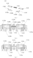
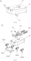
- the power switching device 11 can include a housing 111, a plug 112 housed in the housing 111, and a power switching assembly 113.
- the power switching assembly 113 is adjustable and can be connected to the plug 112.
- each of the first plug member 1121 and the second plug member 1122 may include a positive terminal (1121a, 1122a) and a negative terminal (1121b, 1122b).
- the output terminal 1123 may include a positive output terminal 1123a and a negative output terminal 1123b.
- the output terminal 1123 is connected to the first plug member 1121 and the second plug member 1122 individually, that is, the positive terminal 1121a of the first plug member 1121 or the positive terminal 1122a of the second plug member 1122 is electrically connected to the positive output terminal 1123a of the output terminal 1123, the negative terminal 1121b of the first plug member 1121 or the negative terminal 1122b of the second plug member 1122 is electrically connected to the negative output terminal 1123b of the output terminal 1123 to ensure that the power supply devices is connected to the first plug member 1121 and the second plug member 1122 to realize the output of electrical energy through the output terminal 1123.
- the positive terminals and the negative terminals 1121a, 1122a, 1121b, 1122b of the first plug member 1121 and the second plug member 1122 may be male plugs arranged in a sheet shape, and ends of each male plug are located on the same line.
- Two terminals with the same polarity of the first plug member 1121 and the second plug member 1122 are arranged side by side; further, the output terminal 1123 is a female plug arranged substantially parallel to the first plug member 1121 and the second plug member 1122.
- the output terminal 1123 and the first plug member 1121 and the second plug member 1122 respectively are arranged on two different side walls of the housing 111, so as to facilitate the connection of the first plug member 1121, the second plug member 1122 and the output terminal 1123.
- the positive terminals 1121a, 1122a and negative terminals 1121b, 1122b of the first plug member 1121 and the second plug member 1122 can also be arranged in front and back or up and down, etc., which is different from the linear arrangement.
- the configuration of the first plug member 1121, the second plug member 1122, and the output terminal 1123 can be adjusted according to the specific structure of the power switching assembly 113; that is, according to the invention, the arrangement form and setting form of the first plug member 1121, the second plug member 1122 and the output terminal 1123 can be selected according to actual needs.
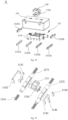
- the switching member 114 includes an elastic member 1141, a first switching member 1142 and a second switching member 1143.
- the first switching member 1142 and the second switching member 1143 are connected by an elastic member 1141.
- the first switching member 1142 is provided with a first connection end 1144 and a protrusion (not numbered) for connecting the elastic member 1141.
- the first connection end 1144 can include a first connecting portion 1144a for connecting the first plug member 1121 and/or the second plug member 1122 and a second connecting portion 1144b extending toward the second switching member 1143 so as to connect the second switching member 1143.
- the second switching member 1143 can include substantially the same structure as the first switching member 1142, that is, the second switching member 1143 is provided with a second connection end 1145 and a protrusion (not labeled) toward the first switching member 1142.
- the second connection end 1145 can also include a third connecting portion 1145a for connecting the first plug member 1121 and/or the second plug member 1122 and a fourth connecting portion 1145b extending toward the first switching member 1142 so as to connect the first switching member 1142.
- the first connection end 1144 and the second connection end 1145 are both integrally formed, and are in an "L" shape and respectively wrapped on outer walls of the first switching member 1142 and the second switching member 1143.
- the positive output terminal 1123a of the output terminal 1123 is electrically connected to the positive terminal 1121a or the positive terminal 1122a through an electrical connection structure such as a wire;
- the negative output terminal 1123b is electrically connected to the negative terminal 1121b or the negative terminal 1122b through an electrical connection structure such as a wire, so that the first energy unit and the second energy unit are connected in parallel, and a low voltage (ie, nV) output is realized through the output terminal 1123.
- first connecting portion 1144a is separated from the positive terminal 1121a of the first plug member 1121
- third connecting portion 1145a is separated from the negative terminal 1122b of the second plug member 1122
- the adjacent negative terminal 1121b and positive terminal 1122a are electrically connected through the first connecting portion 1144a, the third connecting portion 1145a, and the assembly of the second connecting portion 1144b and the fourth connecting portion 1145b.
- the positive output terminal 1123a of the output terminal 1123 is electrically connected to the positive terminal 1121a through an electrical connection structure such as a wire
- the negative output terminal 1123b is electrically connected to the negative terminal 1122b through an electrical connection structure such as a wire.
- the first energy unit and the second energy unit are connected in series, and a high-voltage (i.e., 2nV) output is realized through the output terminal 1123.
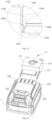
- the control member 115 is used to drive the switching member 114 to move in the track/chute structure, so that the switching member 114 can be switched between the first position and the second position.
- the control member 115 includes a switching button 116, a reset button 117, and a rotary shaft 118.
- the rotary shaft 118 is used for connecting the switching button 116 and the reset button 117 back and forth.
- the switching button 116 is used to control the switching member 114 to slide between the first position and the second position.
- the switching button 116 can include an initial position corresponding to the first position and a switching position corresponding to the second position.
- the switching button 116 includes a pressing portion and a switching portion 1161 connected to the pressing portion. The pressing portion penetrates the housing 111 to drive the switching portion 1161 to move between the initial position and the switching position under the pressing action.
- the switching button 116 when the switching button 116 is in the initial position, the two snapping arms 1162 are both located above the switching member 114, and the switching member 114 is in the first position; when the switching button 116 is moved to the switching position while is pressed, the switching member 114 is snapped between the two snapping arms 1162, and is in the second position.
- each snapping arm 1162 is provided with an inclined guide surface 1163 facing the switching member 114, and the first switching member 1142 and the second switching member 1143 are provided with a resisting surface 1146 corresponding to the inclined guide surface 1163.
- the snapping arms 1162 can slide along the inclined guide surface 1163 and two away side walls of the first switching member 1142 and the second switching member 1143, and is snapped on two away side walls of the switching member 114 in the longitudinal direction.
- the switching button 116 when the switching button 116 is in the initial position, the rotary shaft 118 is in a freely rotating state, and the reset button 117 can move up and down along its extension direction; and at this time, the switching member 114 is in the first position, and the first energy unit and the second energy unit are connected in parallel, and the electric energy storage system 10 can realize a low voltage (i.e., nV) output.
- nV low voltage
- connection end 1243 is provided with a first connection end 1243a, a second connection end 1243b, a third connection end 1243c, and a fourth connection end 1243d that are disposed in a staggered manner and in a direction perpendicular to the chassis 1244, and the four connection ends 1243 are electrically connected to the positive terminal 1121a, the negative terminal 1121b, the positive terminal 1122a, and the negative terminal 1122b respectively.
- each connection end 1243 can include two contacts, the two contacts is located on a end that penetrates the chassis 1244 and is exposed on one side of the chassis 1244 close to the first switching member 1142. The contacts on different connection ends 1243 are arranged in a staggered manner.
- the switching button 116 is arranged in a cylindrical-shape.
- the trigger unit 127 and the switching button 116 are integrally formed.
- the first switching member 1142 is connected and installed on the trigger unit 127.
- the first switching sub-member 1142a and the second switching sub-member 1142b are disposed on the trigger unit 127 in a staggered manner.
- the trigger unit 127 and the chassis 1244 are both arranged in a circular plate shape.
- the trigger unit 127 is provided with a limiting slot 127a
- the chassis 1244 of the second switching member 1143 is provided with a limiting protrusion 1246 corresponding to the limiting slot 127a.
- control member may include, for example, three switching positions.
- the three switching positions include the first position and the second position where the first plug member 1121, the second plug member 1122 and the output terminal 1123 are connected to achieve electrical energy output, and the initial position where the plug 112 of the power switching device 11 is in an open circuit state.
- any one of the first switching members 1142 cannot be connected to different plugs 112 at the same time. At this time, there is no coupling connection relationship between the first plug member 1121 and the second plug member 1122.
- the first energy unit and the second energy unit are in an open circuit state, and the electric energy storage system has no energy output.
- the first switching member 1142 is driven by the trigger unit 127 to rotate on the chassis 1244, and is coupled and connected to the positive terminals 1121a, 1122a, and the negative terminals 1121b, 1122b through the cooperation of the connecting portion and the connection end 1243.
- the contacts of the first connection end 1243a and the third connection end 1243c are electrically connected to the positive terminals 1121a and 1122a through the first switching sub-member 1142a
- the second connection end 1243b and the fourth connection end 1244d are electrically connected to the negative terminals 1121b and 1122b through another first switching sub-member 1142a.
- the first energy unit and the second energy unit are connected in parallel through the switching member and further realize a low voltage (i.e., nV) output through the positive output terminal 1123a and the negative output terminal 1123b of the output terminal 1123.
- the first switching member 1142 is driven by the trigger unit 127 to rotate on the chassis 1244, and is coupled and connected to the positive terminals 1121a, 1122a and the negative terminals 1121b, 1122b through the cooperation of the connecting portion and the connection end 1243.
- the contacts of the second connection end 1243b and the third connection end 1243c are electrically connected to the positive terminal 1122a and negative terminal 1121b through the first switching sub-member 1142a; the contact of the first connection end 1243a is electrically connected to the positive terminal 1121a and the positive output terminal 1123a through the second switching sub-member 1142b; the contact of the fourth connection end 1243d is electrically connected to the negative terminal 1122b and the negative output terminal 1123b through the second switching sub-member 1142b.
- the first energy unit and the second energy unit are connected in series through the switching member, and further realize a high-voltage (i.e., 2nV) output through the output terminal 1123.
- the power switching assembly 113 further includes an intermediate connecting member 136.
- the intermediate connecting member 136 is used for connecting the switching member 114 with the first plug member 1121, the second plug member 1122, and the output terminal 1123, and the switching member 114 is rotatably connected in the intermediate connecting member 136 through the rotating shaft 1341.
- the intermediate connecting member 136 is provided with many intermediate connecting plates for connecting the first plug member 1121, the second plug member 1122 and/or the output terminal 1123. Each of intermediate connecting plates may be a metal intermediate connecting member made of conductive metal material.
- the switching member 114 is electrically connected to the first plug member 1121, the second plug member 1122, and the output terminal 1123 through the metal intermediate connecting member, so as to realize the power transmission of the power switching device 11.
- the switching member 114 is a plate with a certain arc.
- the plate with a certain arc may be a warping plate or an arc-shaped plate, so that the plane where the switching member 114 is located on intersects the plane where the intermediate connecting member 136 is located on.
- the switching member 114 is driven by the power switching assembly 113 to rotate around the rotating shaft 1341, and both ends of the switching member 114 abut on the intermediate connecting member 136 and/or the assembly of the first plug member 1121 and the second plug member 1122, so as to realize the switching of the coupling form of the first plug member 1121 and the second plug member 1122.
- an end of the switching member 114 is provided with protrusions (1342a, 1342c) for improving the electrical contact performance, and the protrusions are respectively disposed corresponding to the positive terminals 1121a and 1122a and the negative terminals 1121b and 1122b of the first plug member 1121 and the second plug member 1122.
- the switching member 114 includes a first switching member 1142 and a second switching member 1143.
- the first switching member 1142 and the second switching member 1143 are arranged in parallel and side by side.
- the first switching member 1142 and the second switching member 1143 is fixedly connected through an arc-shaped connecting portion (not labeled), so that the switching member 114 is generally arranged in an "H" shape.
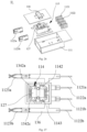
- the control member 115 can rotate in the housing 111 to drive the switching member 114 to move between the first position and the second position.
- the control member 115 is a warping member arranged in a warping switch structure corresponding to the switching member 114.
- the control member 115 includes a switching button 116 provided on the housing 111, a trigger unit 127 provided corresponding to the switching button 116, and a driving section 139 that abuts against the switching member114.
- the switching button 116 is movably arranged on the housing 111, and the trigger unit 127 is fixed in the housing space of the housing 111 through a rotating shaft 1381, and is located below the switching button 116, so that the switching button 116 drives the trigger unit 127 to rotate around the shaft 1381. Further, the axis of the rotating shaft 1381 of the trigger unit 127 and the axis of the rotating shaft 1341 of the switching member 114 are located in the same plane or respectively located in two mutually parallel planes.
- one end of the driving portion 139 abuts against the switching member 114, the other end is connected to the trigger unit 127, and the end of the driving portion 139 abutting against the switching member 114 is arranged in an arc-shape to ensure the driving portion 139 can closely abut against the arc-shaped connecting portion of the switching member 114 and drive the switching member 114 to rotate.
- the driving portion 139 abuts against the switching member 114 along a side away from the trigger unit 127 under the action of the elastic element, so that the end/protrusion 1342 of the switching member 114 abuts and is tightly snapped on the plug 112/the intermediate connecting member 136 to ensure the stability of the power transmission of the power switching device 11 in the process of the rotation of the switching member 114 driven by the control member 115.
- the switching button 116 When the switching button 116 is rotated, the switching button 116 can be limited to a fixed position under the action of the limiting pillar 1481 and the resisting pillar, so as to prevent the switching member 114 connected to the control member 115 from swinging freely between the first position and the second position.
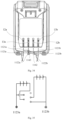
- the control member 115 includes a switching button 116 penetrating through the housing 111 and a trigger unit 127 corresponding to the switching button 116.
- the switching member 114 is connected to the trigger unit 127 and is a conductive switching member which can be electrically connected.
- the trigger unit 127 can be driven by the switching button 116 to slide left and right in a direction perpendicular to the plugging direction, and further the switching member 114 connected to the trigger unit 127 is driven by the switching button 116 to switch between the first position and the second position.
- the switching button 116 includes a sliding block 1761 for connecting the trigger unit 127.
- the sliding block 1761 and the switching button 116 are provided separately to facilitate the assembly of the power switch device 11.
- the sliding block 1761 can also be integrally formed with the switching button 116.
- the trigger unit 127 includes a first trigger unit 1271 and a second trigger unit 1272 arranged in parallel, and each trigger unit 127 can include a convex block (not labeled) for connecting the sliding block 1761, and the sliding block 1761 are provided with accommodating grooves (not labeled) corresponding to the convex blocks, and the accommodating grooves are arranged in left and right and in a staggered manner along the plugging direction, so that the first trigger unit 1271 and the second trigger unit 1272 are arranged in a staggered manner along the sliding direction of the switching button 116; Furthermore, two ends of each trigger unit 127 are connected with elastic members 1141, which can facilitate the control of the member 115 to toggle.
- the switching member 114 includes a first switching member 1142, a second switching member 1143, a third switching member 1144, a fourth switching member and a fifth switching member 1146.
- the first switching member 1142 and a second switching member 1143 are connected to the first trigger unit 1271, and the third switching member 1144, the fourth switching member 1145 and the fifth switching member 1146 are connected to the second trigger unit 1272.
- the first switching member 1142, the second switching member 1143, and the fourth switching member 1145 each are provided with "U"-shaped or substantially “U”-shaped connecting portions (not labeled) for connecting the positive terminals and the negative terminals 1121a, 1122a, 1121b, 1122b, the third switching member 1144 and the fifth switching member 1146 are both arranged in a sheet shape.
- control member 115 also has at least a first switching position corresponding to the first position and a second switching position corresponding to the second position.
- first switching position corresponding to the first position
- second switching position corresponding to the second position.
- the first switching member 1142 is electrically connected to the positive terminals 1121a, 1122a of the first plug member 1121 and the second plug member 1122;
- the second switching member 1143 is electrically connected to the negative terminals 1121b and 1122b in the first plug member 1121 and the second plug member 1122;
- the third switching member 1144, the fourth switching member 1145, and the fifth switching member 1146 are in a free state; so that the first energy unit and The second energy unit is connected in parallel, and further a low voltage (i.e. nV) output is realized through the positive output terminal 1123a and the negative output terminal 1123b of the output terminal 1123.
- nV low voltage
- the switching member 114 when the control member 115 is in the second switching position, the switching member 114 is in the second position. At this time, the first switching member 1142 and the second switching member 1143 are in a free state; two ends of the fourth switching member 1145 are respectively connected to the negative terminal 1121b of the first plug member 1121 and the positive terminal 1122a of the second plug member 1122.
- the third switching member 1144 is electrically connected to the positive terminal 1121a through an electrical connection structure such as a wire; the fifth switching member 1146 is connected to the negative output terminal 1123b through an electrical connection structure such as a wire; so that the first energy unit and the second energy unit are connected in series, and a high-voltage (i.e., 2nV) output is realized through the output terminal 1123.
- a high-voltage (i.e., 2nV) output is realized through the output terminal 1123.
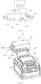
- an electric energy storage system is provided.
- the electric energy storage system can include roughly the same structure as the above-mentioned electric energy storage system.
- the main difference is that the structure of the power switching device 11 for realizing the switching between the first position and the second position by pushing and pulling is different.
- the power switching device 11 can include a housing 111, a plug 112 housed in the housing 111, and a power switching assembly 113 that is adjustable and connected to the plug 112.
- the plug 112 includes a first plug member 1121 and a second plug member 1122, and an output terminal 1123 for realizing electric energy output, and both the first plug member 1121 and the second plug member 1122 have positive terminals (1121a, 1122a) and negative terminals (1121b, 1122b).
- the output terminal 1123 can include a positive output terminal 1123a and a negative output terminal 1123b.
- switching buttons 116 of the control member 115 further includes first switching buttons 116a and second switching buttons 116b for respectively controlling the movement of the first trigger unit 1271 and the second trigger unit 1272,.
- the first switching button 116a and the second switching button 116b are respectively disposed at one end of the first trigger unit 1271 and the second trigger unit 1272 along vertical plugging direction and located at the same side of the housing 111.
- a resisting member 178' is further disposed between the first trigger unit 1271 and the second trigger unit 1272. The setting of the resisting member 178' can ensure that only one trigger unit 127 is driven by the switching button 116 at the same time. This arrangement can effectively avoid the short circuit of the electric tool and the power supply device connected to the two ends of the power switching device 11 due to misoperation.
- the control member 115 can include an initial position, a first switching position corresponding to the first position, and a second switching position corresponding to the second position.
- the switching member 114 is separated from the positive and negative terminals 1121a, 1122a, 1121b, 1122b, the first energy unit and the second energy unit are both in a disconnected state, and the output terminal 1123 does not output electric energy to the outside.
- the switching member 114 when the control member 115 is in the second switching position, the switching member 114 is in the second position. At this time, the first energy unit and the second energy unit are connected in series through the fourth switching member 1145 and the cooperation of the positive and negative terminals 1121b and 1122a, and further a high-voltage(i.e. 2nV) output is realized through the cooperation of the third switching member 1144, the fifth switching member 1146, the positive terminal 1121a, the negative terminal 1122b and the positive and negative outputs 1123a, 1123b of the output terminal 1123.
- a high-voltage(i.e. 2nV) output is realized through the cooperation of the third switching member 1144, the fifth switching member 1146, the positive terminal 1121a, the negative terminal 1122b and the positive and negative outputs 1123a, 1123b of the output terminal 1123.
- an electric energy storage system is provided.
- the electric energy storage system also includes a first energy unit and a second energy unit.
- the main difference is that the power switching device 11 is a switching device that switches between the first position and the second position by pulling and pushing.
- the power switching device 11 includes a housing 111, a plug 112 housed in the housing 111, and a power switching assembly 113 that is adjustable and connected to the plug 112.
- the plug 112 includes a first plug member 1121 and a second plug member 1122, and an output terminal 1123 for realizing electric energy output, and both the first plug member 1121 and the second plug member 1122 have positive terminals (1121a, 1122a) and negative terminals (1121b, 1122b).
- the output terminal 1123 can include a positive output terminal 1123a and a negative output terminal 1123b.
- the power switching device 11 includes a switching member 114 for separating two adjacent plugs 112, and the switching member 114 is, for example, an insulating switching member made of an insulating material.
- the control member 115 includes a switching button 116 penetrating through the housing 111 and a trigger unit 127 corresponding to the switching button 116.
- the trigger unit 127 is slidably received in the housing 111 and can slide along the plugging direction under the drive of the switching button 116.
- An elastic member 1141 is provided at one end of the trigger unit 127 opposite to the switching button 116, so that the trigger unit 127 can conveniently and quickly drive the switching member 114 switch between in the first position and the second position under the combined action of the switching button 116 and the elastic member 1141.
- the switching member 114 can include a first switching member 1142 and a second switching member 1143 that are arranged in parallel on both sides of the movement direction (i.e., the plugging direction) of the trigger unit 127.
- the positive and negative terminals are arranged adjacently in the plug 112, that is, the positive terminal 1121a and the positive terminal 1122a, the positive terminal 1122a and the negative terminal 1121b, the negative terminal 1121b and the negative terminal 1122b are all provided with connecting protrusions for electrical connection with each other.
- the connecting protrusions between the positive terminal 1121a and the positive terminal 1122a, the negative terminal 1121b and the negative terminal 1122b are located on the same straight line, and the connecting protrusions between the positive terminal 1122a and the negative terminal 1121b are arranged in a staggered manner.
- the control member 115 in this embodiment can have a first switching position corresponding to the first position and a second switching position corresponding to the second position.
- the switching member 114 is separated from the first plug member 1121 and the second plug member 1122.
- the positive terminal 1121a and the positive terminal 1122a, the negative terminal 1121b and the negative terminal 1122b are connected to each other through the connecting protrusions.
- the connection protrusions between the positive terminal 1122a and the negative terminal 1121b are separated from each other, so that the first energy unit and the second energy unit are connected in parallel, and further a low voltage (i.e. nV) output is realized through the positive output terminal 1123a and the negative output terminal 1123b of the output terminal 1123.
- nV low voltage
- the switching member 114 when the control member 115 is in the second switching position, the switching member 114 is in the second position. At this time, the first switching member 1142 and the second switching member 1143 are respectively driven by the switching button 116 and the trigger unit 127 to move to the position between the positive terminal 1121a and the positive terminal 1122a, the negative terminal 1121b and the negative terminal 1122b, in order to separate the positive terminal 1121a and the positive terminal 1122a, the negative terminal 1121b and the negative terminal 1122b.
- the connecting protrusions between the positive terminal 1122a and the negative terminal the terminals 1121b are electrically connected to each other under the action of deformation, so that the first energy unit and the second energy unit are connected in series, and a high-voltage (i.e. 2nV) output is further realized through the positive output terminal 1123a and the negative output terminal 1123b of the output terminal 1123.
- an electric energy storage system is further provided.
- the electric energy storage system also includes a first energy unit and a second energy unit.
- the main difference is that the power switching device 11 is a switching device that switches between the first position and the second position by pushing and pulling.
- the power switching device 11 includes a housing 111, a plug 112 housed in the housing 111, and an power switching assembly (not labeled) that is adjustable and connected to the plug 112.
- the plug 112 includes a first plug member 1121 and a second plug member 1122, and an output terminal 1123 for realizing electric energy output, and both the first plug member 1121 and the second plug member 1122 have positive terminals (1121a, 1122a) and negative terminals (1121b, 1122b), the output terminal 1123 can include a positive output terminal 1123a and a negative output terminal 1123b.
- the switching member 114 includes a first switching member 1142, a second switching member 1143, and a third switching member 1144.
- the first switching member 1142 and the second switching member 1143 are arranged in parallel on both sides of the movement direction (that is, the plugging direction) of the trigger unit 127.
- the third switching member 1144 is disposed between the first switching member 1142 and the second switching member 1143.
- the first switching member 1142 and the second switching member 1143 are made of an insulating material
- the third switching member 1144 is made of a conductive material.
- the control member includes a switching button 116 penetrating through the housing 111 and a trigger unit 127 corresponding to the switching button 116.
- the trigger unit 127 is slidably accommodated in the housing 111 and can be driven by the switching button 116 to slide in the plugging direction.
- An elastic member 1141 is provided at one end of the trigger unit 127 opposite to the switching button 116, so that the trigger unit 127 can conveniently and quickly drive the switching member 114 to switch between the first position and the second position under the combined action of the switching button 116 and the elastic member 1141.
- the control member in this embodiment can include a first switching position corresponding to the first position and a second switching position corresponding to the second position.
- the switching member 114 is separated from the first plug member 1121 and the second plug member 1122.
- the positive terminal 1121a and the positive terminal 1122a, the negative terminal 1121b and the negative terminal 1122b are electrically connected to each other through connecting protrusions, so that the first energy unit and the second energy unit are connected in parallel, and a low voltage (i.e., nV) output is further realized through the positive output terminal 1123a and the negative output terminal 1123b of the output terminal 1123.
- nV low voltage
- the switching member 114 when the control member is in the second switching position, the switching member 114 is in the second position. At this time, the first switching member 1142 is plugged between the positive terminal 1121a and the positive terminal 1122a.
- the switching member 1143 is plugged between the negative terminal 1121b and the negative terminal 1122b to separate the positive terminal 1121a and the positive terminal 1122a, and the negative terminal 1121b and the negative terminal 1122b.
- the third switching member 1144 abuts on the negative terminal 1121b and the positive terminal 1122a, and are electrically connected to the negative terminal 1121b and the positive terminal 1122a, so that the first energy unit and the second energy unit are connected in series, and a high-voltage (i.e. 2nV) output is realized through the positive output terminal 1123a and the negative output terminal 1123b of the output terminal 1123.
- an electric energy storage system is provided.
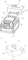
- the electric energy storage system can include the same structure as the above-mentioned electric energy storage system. The only difference is that the positive electrodes 12a', 13a' and the negative electrodes 12b', 13b' of the first energy unit and the second energy unit are arranged up and down.
- an electric energy storage system is provided.
- the difference between this electric energy storage system and the above-mentioned electric energy storage system is only: the positive electrodes 12a", 13a" and the negative electrodes 12b", 13b" of the first energy unit and the second energy unit are arranged front and back along the direction of the power switching device 11 and the energy unit, and the negative electrodes 12b", 13b" are parallel to the positive electrode 12a", 13a".
- the arrangement of the plugs 112 in the power switching device 11 can be adjusted according to the arrangement of the positive and negative electrodes of the first energy unit and the second energy unit.
- the first energy unit and the second energy unit are connected in parallel, and when the power switching device 11 is in the second position, the first energy unit and the second energy unit can be connected in series, that is, the arrangement form of the plugs 112 of the power switching device 11 in can be adjusted according to the actual situation, which is not limited here.
- the electric tool includes a tool body and a power switching device 11 for electrically connecting the tool body and a power supply device.
- the tool body can include a plug-in portion for connecting the power switching device 11, the plug-in portion can include two connecting pieces with opposite polarities, and the two connecting pieces with opposite polarities are respectively connected to the positive output terminal 1123a and the negative output terminal 1123b of the output terminal 1123 of the power switching device 11 with the same polarity to ensure the normal input of a working voltage.
- the electric tool can be connected to a dual-voltage power supply device or a single-voltage power supply device with two energy units with an output voltage of n/2V, and in this embodiment, each energy unit with an output voltage of n/2V can include two output electrodes with opposite polarities.
- the power switching device 11 when the electric tool is electrically connected to the dual-voltage power supply device/single-voltage power supply device through the power switching device 11, the power switching device 11 are respectively electrically connected to the output electrodes of the two energy units with an output voltage of n/2V through the positive terminal 1121a and the negative terminal 1121b of the first plug member 1121 and the positive terminal 1122a and the negative terminal 1122b of the second plug member 1122.
- the switching member 114 can be driven by the switching button 116 to move to the second position, so that the negative terminal 1121b of the first plug member 1121 and the positive terminal 1122a of the second plug member 1122 are electrically connected through the switching member 114, so as to control the series connection of two energy units with an output voltage of n/2V, the output voltage of the dual-voltage power supply device or the single-voltage power supply device is nV, which meets the rated voltage of the tool body of the electric tool and ensures the normal operation of the electric tool.
- the electric tool can be connected to a dual-voltage power supply device or a single-voltage power supply device with two energy units with an output voltage of nV, and each energy unit with an output voltage of nV can include two output electrodes of opposite polarities.
Landscapes
- Engineering & Computer Science (AREA)
- Power Engineering (AREA)
- Details Of Connecting Devices For Male And Female Coupling (AREA)
- Surgical Instruments (AREA)
- Electrical Discharge Machining, Electrochemical Machining, And Combined Machining (AREA)
- Brushes (AREA)
- Charge And Discharge Circuits For Batteries Or The Like (AREA)
Claims (8)
- Leistungsschaltvorrichtung (11), umfassend:einen Stecker (112), der mit einer Leistungsversorgungsvorrichtung verbunden ist und einen Ausgangsanschluss (1123) umfasst;eine Leistungsschaltanordnung (113), die mit dem Stecker (112) verbunden ist und ein Schaltelement (114) umfasst, wobei das Schaltelement (114) zum Umschalten einer Kopplungsform des Steckers (112) konfiguriert ist, undein Steuerelement (115), das zum Steuern der Leistungsschaltanordnung (113) konfiguriert ist, um sich zwischen verschiedenen Schaltpositionen zu bewegen, wobei das Steuerelement (115) eine Schalttaste (116) umfasst,dadurch gekennzeichnet, dass die Schaltpositionen der Leistungsschaltanordnung (113) durch Drücken der Schalttaste (116) geschaltet werden,wobei die Schalttaste (116) verwendet wird, um das Schaltelement (114) zu steuern, um sich zwischen einer ersten Position und einer zweiten Position zu verschieben, wobei sich die Schalttaste (116) in einer Ausgangsposition, die der ersten Position des Schaltelements (114) entspricht, und einer Schaltposition befinden kann, die der zweiten Position des Schaltelements (114) entspricht, wobei die Schalttaste (116) einen Druckabschnitt und einen mit dem Druckabschnitt verbundenen Schaltabschnitt (1161) beinhaltet, wobei der Druckabschnitt in das Gehäuse (111) eindringt, um den Schaltabschnitt (1161) anzutreiben, um sich unter Druckeinwirkung zwischen der Ausgangsposition und der Schaltposition zu bewegen, wobei der Schaltabschnitt (1161) gebildet ist, um sich entlang einer Erstreckungsrichtung senkrecht zum Druckabschnitt nach außen zu erstrecken, wobei der Schaltabschnitt (1161) zwei Rastarme (1162) beinhaltet, die sich in Richtung des Schaltelements (114) erstrecken und parallel zueinander angeordnet sind, wobei ein Abstand zwischen den zwei Rastarmen (1162) kleiner ist als eine Länge des Schaltelements (114) an der ersten Position, wobei, wenn sich die Schalttaste (116) in der Ausgangsposition befindet und sich das Schaltelement (114) in der ersten Position befindet, sich die zwei Rastarme (1162) über dem Schaltelement (114) befinden, und wenn die Schalttaste (116) zur Schaltposition bewegt wird, während sie gedrückt wird, das Schaltelement (114) zwischen den zwei Rastarmen (1162) einrastet, und sich in der zweiten Position befindet, wobei das Schaltelement (114) ein elastisches Element (1141), ein erstes Schaltelement (1142) und ein zweites Schaltelement (1143) beinhaltet, wobei das erste Schaltelement (1142) und das zweite Schaltelement (1143) über das elastische Element (1141) verbunden sind, wobei sich das Schaltelement (114) in der zweiten Position befindet, wenn sich das elastische Element (1141) unter der Steuerung des Steuerelements (115) in einem zusammengedrückten Zustand befindet.
- Leistungsschaltvorrichtung (11) nach Anspruch 1, wobei das erste Schaltelement (1142) mit einem ersten Anschlussende (1144) und einem Vorsprung zum Verbinden des elastischen Elements (1141) bereitgestellt ist, wobei ein Ende jedes der zwei Rastarme (1162) mit einer geneigten Führungsoberfläche (1163) bereitgestellt ist, die dem Schaltelement (114) zugewandt ist, und das erste Schaltelement (1142) und das zweite Schaltelement (1143) mit einer Widerstandsoberfläche (1146) bereitgestellt sind, die der geneigten Führungsoberfläche (1163) entspricht.
- Leistungsschaltvorrichtung (11) nach Anspruch 1, wobei da das erste Schaltelement (1142) mit einem ersten Anschlussende (1144) und einem Vorsprung zum Verbinden des elastischen Elements (1141) bereitgestellt ist, wobei zwei abgewandte Seitenwände des ersten Schaltelements (1142) und des zweiten Schaltelements (1143) beide mit Positionsbegrenzungsstrukturen (1147) bereitgestellt sind, und wobei die zwei Rastarme (1162) mit Positionierungsstrukturen (1164) bereitgestellt sind, die den Begrenzungsstrukturen (1147) entsprechen, die Begrenzungsstruktur (1147) eine Begrenzungsnut ist und die Positionierungsstruktur (1164) ein Positionierungsvorsprung ist, welcher der Begrenzungsnut entspricht.
- Leistungsschaltvorrichtung (11) nach einem der vorstehenden Ansprüche, wobei der Stecker (112) ein erstes Steckerelement (1121) und ein zweites Steckerelement (1122) umfasst und Anschlüsse mit gleicher Polarität jeweils des ersten Steckerelements (1121) und des zweiten Steckerelements (1122) über das Schaltelement (114) verbunden sind, wenn sich das Schaltelement (114) in der ersten Position befindet, Anschlüsse mit entgegengesetzten Polaritäten jeweils des ersten Steckerelements (1121) und des zweiten Steckerelements (1122) durch das Schaltelement (114) verbunden sind, wenn sich das Schaltelement in der zweiten Position befindet.
- Leistungsschaltvorrichtung (11) nach Anspruch 4, wobei ein positiver Ausgangsanschluss (1123a) des Ausgangsanschlusses (1123) elektrisch mit einem positiven Anschluss eines des ersten Steckerelements (1121) und des zweiten Steckerelements (1122) verbunden ist, ein negativer Ausgangsanschluss (1123b) des Ausgangsanschlusses (1123) elektrisch mit einem negativen Anschluss eines des ersten Steckerelements (1121) und des zweiten Steckerelements (1122) verbunden ist.
- Elektrisches Energiespeichersystem, umfassend:die Leistungsschaltvorrichtung (11) nach einem der vorstehenden Ansprüche,eine erste Energieeinheit; undeine zweite Energieeinheit, die über die Leistungsschaltvorrichtung (11) mit der ersten Energieeinheit verbunden ist, wobei die Leistungsschaltvorrichtung (11) zum Ändern von Serien-Parallel-Verbindungen zwischen der ersten Energieeinheit und der zweiten Energieeinheit durch Umschalten von Schaltpositionen konfiguriert ist.
- Elektrisches Energiespeichersystem nach Anspruch 6, wobei das Schaltelement (114) mit Elektroden mit gleicher Polarität der ersten Energieeinheit und der zweiten Energieeinheit einzeln verbunden ist, wenn sich das Schaltelement (114) in der ersten Position befindet, um einen Niederspannungsausgang aus dem elektrischen Energiespeichersystem zu realisieren, und das Schaltelement (114) mit Elektroden mit entgegengesetzten Polaritäten der ersten Energieeinheit und der zweiten Energieeinheit einzeln verbunden ist, wenn sich das Schaltelement (114) in der zweiten Position befindet, um einen Hochspannungsausgang aus dem elektrischen Energiespeichersystem zu realisieren.
- Elektrowerkzeug, umfassend:ein elektrisches Energiespeichersystem; unddie Leistungsschaltvorrichtung (11) nach einem der Ansprüche 1 bis 5, die betrieblich mit dem elektrischen Energiespeichersystem zusammenwirkt, um eine Ausgangsspannung aus dem elektrischen Energiespeichersystem auf eine Nennspannung des Elektrowerkzeugs anzugleichen.
Applications Claiming Priority (6)
| Application Number | Priority Date | Filing Date | Title |
|---|---|---|---|
| CN202010186739.1A CN111243879B (zh) | 2020-03-17 | 2020-03-17 | 电能切换组件及具有该电能切换组件的工具及系统 |
| CN202010194193.4A CN111261434B (zh) | 2020-03-17 | 2020-03-17 | 电能切换组件及具有该电能切换组件的工具及系统 |
| CN202010186781.3A CN111933837B (zh) | 2020-03-17 | 2020-03-17 | 电能切换组件及具有该电能切换组件的工具及系统 |
| CN202010187354.7A CN111262107B (zh) | 2020-03-17 | 2020-03-17 | 电能切换构件及具有该电能切换构件的工具及系统 |
| CN202010186774.3A CN111463884B (zh) | 2020-03-17 | 2020-03-17 | 电能切换组件及具有该电能切换组件的工具及系统 |
| PCT/CN2021/080950 WO2021185228A1 (zh) | 2020-03-17 | 2021-03-16 | 电能切换组件及具有电能切换组件的工具和系统 |
Publications (4)
| Publication Number | Publication Date |
|---|---|
| EP4109686A1 EP4109686A1 (de) | 2022-12-28 |
| EP4109686A4 EP4109686A4 (de) | 2023-08-30 |
| EP4109686C0 EP4109686C0 (de) | 2025-07-09 |
| EP4109686B1 true EP4109686B1 (de) | 2025-07-09 |
Family
ID=77771472
Family Applications (1)
| Application Number | Title | Priority Date | Filing Date |
|---|---|---|---|
| EP21771459.1A Active EP4109686B1 (de) | 2020-03-17 | 2021-03-16 | Elektrische energieschaltanordnung, werkzeug mit elektrischer energieschaltanordnung und system |
Country Status (5)
| Country | Link |
|---|---|
| US (1) | US20230133914A1 (de) |
| EP (1) | EP4109686B1 (de) |
| AU (1) | AU2021239252A1 (de) |
| CA (1) | CA3175614A1 (de) |
| WO (1) | WO2021185228A1 (de) |
Families Citing this family (2)
| Publication number | Priority date | Publication date | Assignee | Title |
|---|---|---|---|---|
| WO2023125153A1 (zh) * | 2021-12-29 | 2023-07-06 | 格力博(江苏)股份有限公司 | 一种系统、供电系统及电动工具系统 |
| CN118888945A (zh) * | 2024-09-27 | 2024-11-01 | 长安绿电科技有限公司 | 一种分布式直流操作电源电池箱 |
Citations (1)
| Publication number | Priority date | Publication date | Assignee | Title |
|---|---|---|---|---|
| EP3660949A1 (de) * | 2018-11-27 | 2020-06-03 | Changzhou Globe Co., Ltd. | Elektrowerkzeugsystem und batteriepack davon |
Family Cites Families (11)
| Publication number | Priority date | Publication date | Assignee | Title |
|---|---|---|---|---|
| US4325107A (en) * | 1980-01-29 | 1982-04-13 | Macleod Richard H | Rechargeable flashlight |
| JP5574138B2 (ja) * | 2006-09-19 | 2014-08-20 | 日立工機株式会社 | アダプタ、電池パックとアダプタの組み合わせ、及びそれらを備えた電動工具 |
| CN101924379A (zh) * | 2010-04-12 | 2010-12-22 | 常州格力博工具有限公司 | 电池包及电池包与电气装置的组合 |
| CN202142749U (zh) * | 2011-08-11 | 2012-02-08 | 时希领 | 蓄电池串联和并联的转接装置 |
| JP2017045679A (ja) * | 2015-08-28 | 2017-03-02 | 株式会社豊田自動織機 | 蓄電装置 |
| CN207251228U (zh) * | 2017-04-17 | 2018-04-17 | 常州格力博有限公司 | 背负式电源系统 |
| CN111243879B (zh) * | 2020-03-17 | 2025-08-22 | 格力博(江苏)股份有限公司 | 电能切换组件及具有该电能切换组件的工具及系统 |
| CN111262107B (zh) * | 2020-03-17 | 2025-06-24 | 格力博(江苏)股份有限公司 | 电能切换构件及具有该电能切换构件的工具及系统 |
| CN111261434B (zh) * | 2020-03-17 | 2025-10-24 | 格力博(江苏)股份有限公司 | 电能切换组件及具有该电能切换组件的工具及系统 |
| CN111933837B (zh) * | 2020-03-17 | 2023-09-22 | 格力博(江苏)股份有限公司 | 电能切换组件及具有该电能切换组件的工具及系统 |
| CN111463884B (zh) * | 2020-03-17 | 2023-08-22 | 格力博(江苏)股份有限公司 | 电能切换组件及具有该电能切换组件的工具及系统 |
-
2021
- 2021-03-16 WO PCT/CN2021/080950 patent/WO2021185228A1/zh not_active Ceased
- 2021-03-16 AU AU2021239252A patent/AU2021239252A1/en active Pending
- 2021-03-16 EP EP21771459.1A patent/EP4109686B1/de active Active
- 2021-03-16 CA CA3175614A patent/CA3175614A1/en active Pending
- 2021-03-16 US US17/912,047 patent/US20230133914A1/en active Pending
Patent Citations (1)
| Publication number | Priority date | Publication date | Assignee | Title |
|---|---|---|---|---|
| EP3660949A1 (de) * | 2018-11-27 | 2020-06-03 | Changzhou Globe Co., Ltd. | Elektrowerkzeugsystem und batteriepack davon |
Also Published As
| Publication number | Publication date |
|---|---|
| US20230133914A1 (en) | 2023-05-04 |
| EP4109686C0 (de) | 2025-07-09 |
| EP4109686A1 (de) | 2022-12-28 |
| CA3175614A1 (en) | 2021-09-23 |
| EP4109686A4 (de) | 2023-08-30 |
| WO2021185228A1 (zh) | 2021-09-23 |
| AU2021239252A1 (en) | 2022-10-27 |
Similar Documents
| Publication | Publication Date | Title |
|---|---|---|
| EP4109686B1 (de) | Elektrische energieschaltanordnung, werkzeug mit elektrischer energieschaltanordnung und system | |
| EP3660950A2 (de) | Elektrowerkzeugsystem und batteriepack dafür | |
| US11600884B2 (en) | Battery pack | |
| TWI473327B (zh) | 具彈性尺寸及排列方向之電池系統 | |
| EP0528478A1 (de) | Netzunabhängiges Kraftbetriebenes Werkzeug | |
| EP3393722A1 (de) | Handwerkzeugmaschine | |
| US20230261248A1 (en) | Multi-voltage Battery Pack, Power Tool System and Charging System | |
| CN212277052U (zh) | 一种转换开关 | |
| CN111584788B (zh) | 电动工具及电动工具系统 | |
| US8592707B2 (en) | Electrical switch with a contact element mounted such that it can rotate | |
| CN212991201U (zh) | 电动工具及电动工具系统 | |
| CN212587653U (zh) | 电动工具及其系统 | |
| CN111262107B (zh) | 电能切换构件及具有该电能切换构件的工具及系统 | |
| CN111243879B (zh) | 电能切换组件及具有该电能切换组件的工具及系统 | |
| CN111725458B (zh) | 电动工具系统 | |
| CN107658604B (zh) | 多自由度充电结构及电动机器人 | |
| CN111261434B (zh) | 电能切换组件及具有该电能切换组件的工具及系统 | |
| CN111933837B (zh) | 电能切换组件及具有该电能切换组件的工具及系统 | |
| EP1917701A2 (de) | Universelle steckdose | |
| CN111584789A (zh) | 电动工具及其系统 | |
| CN111463884B (zh) | 电能切换组件及具有该电能切换组件的工具及系统 | |
| CN211828518U (zh) | 电能切换装置、电能储存系统、电动工具及系统 | |
| US12542305B2 (en) | Power tool and power tool system | |
| CN211828892U (zh) | 电能切换装置、电能储存系统、电动工具及系统 | |
| CN114639566B (zh) | 开关 |
Legal Events
| Date | Code | Title | Description |
|---|---|---|---|
| STAA | Information on the status of an ep patent application or granted ep patent |
Free format text: STATUS: THE INTERNATIONAL PUBLICATION HAS BEEN MADE |
|
| PUAI | Public reference made under article 153(3) epc to a published international application that has entered the european phase |
Free format text: ORIGINAL CODE: 0009012 |
|
| STAA | Information on the status of an ep patent application or granted ep patent |
Free format text: STATUS: REQUEST FOR EXAMINATION WAS MADE |
|
| 17P | Request for examination filed |
Effective date: 20220920 |
|
| AK | Designated contracting states |
Kind code of ref document: A1 Designated state(s): AL AT BE BG CH CY CZ DE DK EE ES FI FR GB GR HR HU IE IS IT LI LT LU LV MC MK MT NL NO PL PT RO RS SE SI SK SM TR |
|
| DAV | Request for validation of the european patent (deleted) | ||
| DAX | Request for extension of the european patent (deleted) | ||
| A4 | Supplementary search report drawn up and despatched |
Effective date: 20230727 |
|
| RIC1 | Information provided on ipc code assigned before grant |
Ipc: H02J 7/36 20060101ALI20230721BHEP Ipc: H01H 9/00 20060101ALI20230721BHEP Ipc: H01R 29/00 20060101AFI20230721BHEP |
|
| STAA | Information on the status of an ep patent application or granted ep patent |
Free format text: STATUS: EXAMINATION IS IN PROGRESS |
|
| 17Q | First examination report despatched |
Effective date: 20240408 |
|
| GRAP | Despatch of communication of intention to grant a patent |
Free format text: ORIGINAL CODE: EPIDOSNIGR1 |
|
| STAA | Information on the status of an ep patent application or granted ep patent |
Free format text: STATUS: GRANT OF PATENT IS INTENDED |
|
| INTG | Intention to grant announced |
Effective date: 20250331 |
|
| GRAS | Grant fee paid |
Free format text: ORIGINAL CODE: EPIDOSNIGR3 |
|
| GRAA | (expected) grant |
Free format text: ORIGINAL CODE: 0009210 |
|
| STAA | Information on the status of an ep patent application or granted ep patent |
Free format text: STATUS: THE PATENT HAS BEEN GRANTED |
|
| AK | Designated contracting states |
Kind code of ref document: B1 Designated state(s): AL AT BE BG CH CY CZ DE DK EE ES FI FR GB GR HR HU IE IS IT LI LT LU LV MC MK MT NL NO PL PT RO RS SE SI SK SM TR |
|
| REG | Reference to a national code |
Ref country code: GB Ref legal event code: FG4D |
|
| REG | Reference to a national code |
Ref country code: CH Ref legal event code: EP |
|
| REG | Reference to a national code |
Ref country code: IE Ref legal event code: FG4D |
|
| U01 | Request for unitary effect filed |
Effective date: 20250709 |
|
| U07 | Unitary effect registered |
Designated state(s): AT BE BG DE DK EE FI FR IT LT LU LV MT NL PT RO SE SI Effective date: 20250715 |
|
| PG25 | Lapsed in a contracting state [announced via postgrant information from national office to epo] |
Ref country code: IS Free format text: LAPSE BECAUSE OF FAILURE TO SUBMIT A TRANSLATION OF THE DESCRIPTION OR TO PAY THE FEE WITHIN THE PRESCRIBED TIME-LIMIT Effective date: 20251109 |
|
| PG25 | Lapsed in a contracting state [announced via postgrant information from national office to epo] |
Ref country code: NO Free format text: LAPSE BECAUSE OF FAILURE TO SUBMIT A TRANSLATION OF THE DESCRIPTION OR TO PAY THE FEE WITHIN THE PRESCRIBED TIME-LIMIT Effective date: 20251009 |
|
| PG25 | Lapsed in a contracting state [announced via postgrant information from national office to epo] |
Ref country code: HR Free format text: LAPSE BECAUSE OF FAILURE TO SUBMIT A TRANSLATION OF THE DESCRIPTION OR TO PAY THE FEE WITHIN THE PRESCRIBED TIME-LIMIT Effective date: 20250709 |
|
| PG25 | Lapsed in a contracting state [announced via postgrant information from national office to epo] |
Ref country code: GR Free format text: LAPSE BECAUSE OF FAILURE TO SUBMIT A TRANSLATION OF THE DESCRIPTION OR TO PAY THE FEE WITHIN THE PRESCRIBED TIME-LIMIT Effective date: 20251010 |
|
| PG25 | Lapsed in a contracting state [announced via postgrant information from national office to epo] |
Ref country code: PL Free format text: LAPSE BECAUSE OF FAILURE TO SUBMIT A TRANSLATION OF THE DESCRIPTION OR TO PAY THE FEE WITHIN THE PRESCRIBED TIME-LIMIT Effective date: 20250709 |
|
| PG25 | Lapsed in a contracting state [announced via postgrant information from national office to epo] |
Ref country code: RS Free format text: LAPSE BECAUSE OF FAILURE TO SUBMIT A TRANSLATION OF THE DESCRIPTION OR TO PAY THE FEE WITHIN THE PRESCRIBED TIME-LIMIT Effective date: 20251009 |
|
| PG25 | Lapsed in a contracting state [announced via postgrant information from national office to epo] |
Ref country code: ES Free format text: LAPSE BECAUSE OF FAILURE TO SUBMIT A TRANSLATION OF THE DESCRIPTION OR TO PAY THE FEE WITHIN THE PRESCRIBED TIME-LIMIT Effective date: 20250709 |