EP4109107B1 - Automatic analysis device - Google Patents
Automatic analysis device Download PDFInfo
- Publication number
- EP4109107B1 EP4109107B1 EP21757567.9A EP21757567A EP4109107B1 EP 4109107 B1 EP4109107 B1 EP 4109107B1 EP 21757567 A EP21757567 A EP 21757567A EP 4109107 B1 EP4109107 B1 EP 4109107B1
- Authority
- EP
- European Patent Office
- Prior art keywords
- shaft
- arm
- motor
- automatic analyzer
- base
- Prior art date
- Legal status (The legal status is an assumption and is not a legal conclusion. Google has not performed a legal analysis and makes no representation as to the accuracy of the status listed.)
- Active
Links
Images




Classifications
-
- G—PHYSICS
- G01—MEASURING; TESTING
- G01N—INVESTIGATING OR ANALYSING MATERIALS BY DETERMINING THEIR CHEMICAL OR PHYSICAL PROPERTIES
- G01N35/00—Automatic analysis not limited to methods or materials provided for in any single one of groups G01N1/00 - G01N33/00; Handling materials therefor
- G01N35/10—Devices for transferring samples or any liquids to, in, or from, the analysis apparatus, e.g. suction devices, injection devices
- G01N35/1009—Characterised by arrangements for controlling the aspiration or dispense of liquids
-
- G—PHYSICS
- G01—MEASURING; TESTING
- G01N—INVESTIGATING OR ANALYSING MATERIALS BY DETERMINING THEIR CHEMICAL OR PHYSICAL PROPERTIES
- G01N35/00—Automatic analysis not limited to methods or materials provided for in any single one of groups G01N1/00 - G01N33/00; Handling materials therefor
- G01N35/10—Devices for transferring samples or any liquids to, in, or from, the analysis apparatus, e.g. suction devices, injection devices
- G01N35/1065—Multiple transfer devices
- G01N35/1067—Multiple transfer devices for transfer to or from containers having different spacing
-
- B—PERFORMING OPERATIONS; TRANSPORTING
- B01—PHYSICAL OR CHEMICAL PROCESSES OR APPARATUS IN GENERAL
- B01L—CHEMICAL OR PHYSICAL LABORATORY APPARATUS FOR GENERAL USE
- B01L3/00—Containers or dishes for laboratory use, e.g. laboratory glassware; Droppers
- B01L3/02—Burettes; Pipettes
- B01L3/021—Pipettes, i.e. with only one conduit for withdrawing and redistributing liquids
- B01L3/0217—Pipettes, i.e. with only one conduit for withdrawing and redistributing liquids of the plunger pump type
- B01L3/0227—Details of motor drive means
-
- G—PHYSICS
- G01—MEASURING; TESTING
- G01N—INVESTIGATING OR ANALYSING MATERIALS BY DETERMINING THEIR CHEMICAL OR PHYSICAL PROPERTIES
- G01N35/00—Automatic analysis not limited to methods or materials provided for in any single one of groups G01N1/00 - G01N33/00; Handling materials therefor
- G01N35/10—Devices for transferring samples or any liquids to, in, or from, the analysis apparatus, e.g. suction devices, injection devices
- G01N35/1065—Multiple transfer devices
-
- G—PHYSICS
- G01—MEASURING; TESTING
- G01N—INVESTIGATING OR ANALYSING MATERIALS BY DETERMINING THEIR CHEMICAL OR PHYSICAL PROPERTIES
- G01N35/00—Automatic analysis not limited to methods or materials provided for in any single one of groups G01N1/00 - G01N33/00; Handling materials therefor
- G01N35/02—Automatic analysis not limited to methods or materials provided for in any single one of groups G01N1/00 - G01N33/00; Handling materials therefor using a plurality of sample containers moved by a conveyor system past one or more treatment or analysis stations
- G01N35/04—Details of the conveyor system
- G01N2035/0474—Details of actuating means for conveyors or pipettes
-
- G—PHYSICS
- G01—MEASURING; TESTING
- G01N—INVESTIGATING OR ANALYSING MATERIALS BY DETERMINING THEIR CHEMICAL OR PHYSICAL PROPERTIES
- G01N35/00—Automatic analysis not limited to methods or materials provided for in any single one of groups G01N1/00 - G01N33/00; Handling materials therefor
- G01N35/10—Devices for transferring samples or any liquids to, in, or from, the analysis apparatus, e.g. suction devices, injection devices
- G01N35/1065—Multiple transfer devices
- G01N35/1067—Multiple transfer devices for transfer to or from containers having different spacing
- G01N2035/1069—Multiple transfer devices for transfer to or from containers having different spacing by adjusting the spacing between multiple probes of a single transferring head
-
- G—PHYSICS
- G01—MEASURING; TESTING
- G01N—INVESTIGATING OR ANALYSING MATERIALS BY DETERMINING THEIR CHEMICAL OR PHYSICAL PROPERTIES
- G01N35/00—Automatic analysis not limited to methods or materials provided for in any single one of groups G01N1/00 - G01N33/00; Handling materials therefor
- G01N35/10—Devices for transferring samples or any liquids to, in, or from, the analysis apparatus, e.g. suction devices, injection devices
- G01N35/1065—Multiple transfer devices
- G01N2035/1076—Multiple transfer devices plurality or independently movable heads
Definitions
- the invention relates to an automatic analyzer.
- a dispensing mechanism of a reagent or a specimen in an automatic analyzer is formed by a probe for sucking and discharging the reagent and the like, an arm for supporting the probe, and a driving mechanism for driving the arm.
- the probe vertically moves to each stopping position as well as horizontally moves to a suction position and a discharge position of the reagent and the like and a cleaning position where to clean the probe.
- a dispensing mechanism having a rotational degree of freedom along two axes with respect to a horizontal movement, what is called, a structure of two-link arm.
- FIG. 2 is a perspective view showing a state (a) before an arm is lowered and a state (b) after the arm is lowered.
- a motor 28 is used to rotate a first shaft 26, thereby driving an inside arm 25, and a motor 33 is used to rotate a second shaft 31, thereby driving an outside arm 30.
- the first shaft 26 is lowered while rotating a rotary ball spline
- the second shaft 31 is lowered while rotating a ball spline 55.
- the reagent disk 9 can mount a plurality of reagent bottles 10 on its circumference.
- the reagent disk 9 is kept cool.
- Rotatable and vertically-movable reagent dispensing mechanisms 7 and 8 are arranged between the reaction disk 1 and the reagent disk 9.
- the reagent dispensing mechanisms 7 and 8 have the respective reagent probes 7a and 8a with the syringes for reagent 18 and 18a connected, and the reagent probes 7a and 8a move along arc around the rotation axes, get access to the reagent disk 9, and dispense the reagent from the reagent bottle 10 to the reaction container 2.
- Analysis processing of an inspection specimen by the automatic analyzer is generally executed according to the following steps. At first, a specimen within the specimen container 15 mounted on the specimen rack 16 which is carried near the reaction disk 1 by the specimen transport mechanism 17 is dispensed to the reaction container 2 on the reaction disk 1 according to the specimen probe 11a of the specimen dispensing mechanism 11. Next, a reagent to be used for analysis is dispensed from the reagent bottle 10 on the reagent disk 9 to the reaction container 2 in which the sample has been previously dispensed, according to the reagent probe 7a of the reagent dispensing mechanism 7 or the reagent probe 8a of the reagent dispensing mechanism 8. Continuously, the stirring mechanism 5 stirs the mixed liquid of the specimen and the reagent within the reaction container 2.
- the light generated from the light source 4a is transmitted through the reaction container 2 containing the mixed liquid, and the light intensity of the transmitted light is measured by the spectrophotometer 4.
- the light intensity measured by the spectrophotometer 4 is sent to the controller 21 through an A/D converter and an interface.
- the controller 21 calculates, for example, the concentration and the like of a predetermined component of the analysis item according to the reagent from the absorbance of the mixed liquid (reaction liquid).
- the obtained measurement results are displayed on a display unit (not shown) or the like.
- Fig. 3 is a perspective view wherein, regarding the dispensing mechanism according to the embodiment, an arm and a base 24 are omitted.
- the dispensing mechanism according to the embodiment has a first shaft 26 and a second shaft, as a shaft transmitting power to an arm while supporting the arm.
- the first shaft 26 is a rotation axis for rotating a first arm
- the second shaft is a rotation axis for rotating a second arm.
- the second shaft is divided into an upper shaft 41 and a lower shaft 40 in an axial direction and they have different diameters.
- the power of the motor 28 is used.
- a pulley on the driving side built in the motor 28 is connected to a pulley 27 on the driven side through a belt 29, and the pulley 27 is further fixed to a rotary ball spline 51 (a sleeve portion 511 in Fig. 5 ).
- the rotary ball spline 51 as a ball spline for the first shaft slidably supports the first shaft 26 as a spline shaft and can transmit the torque of the pulley 27 to the first shaft 26. Therefore, the rotational power of the motor 28 is transmitted to the first shaft 26 through the belt 29, the pulley 27, and the rotary ball spline 51.
- the first shaft 26 slides onto the pulley 27 and the rotary ball spline 51, which enables the vertical movement of the first shaft 26.
- the pulley 27 on the driven side is reduced in speed by enlarging its diameter more than that of the pulley on the driving side, hence to be able to reduce the load due to the inertia at the rotation time of the first arm.
- the power of the motor 33 is used.
- a pully on the driving side built in the motor 33 is connected to a pulley 32 on the driven side through a belt 34 and further the pulley 32 is fixed to the lower end of the lower shaft 40.
- the lower shaft 40 as the spline shaft is slidably supported by a ball spline 43 as a ball spline for the lower shaft.
- the ball spline 43 is fixed to a joint 44, and further the joint 44 is fixed to the upper shaft 41 (refer to Fig. 5 ). Therefore, the rotation power of the motor 33 is transmitted to the upper shaft 41 through the belt 34, the pulley 32, and the lower shaft 40.
- the pulley 32 on the driven side is reduced in speed by enlarging its diameter more than that of the pulley on the driving side, hence to be able to reduce the load due to the inertia at the rotation time of the second arm.
- a belt 38 for vertical movement is endlessly wound around a pully on the driving side built in the motor 37 and a pulley 39 on the driven side.
- a joint 36 is fixed to the belt 38 connecting these two pulleys on the side of the same moving direction as the first shaft 26, and a balance weight 53 is fixed on the side of the moving direction opposite to the moving direction of the first shaft 26.
- the joint 36 is formed integrally with the slider 35.
- the balance weight 53 is to reduce the torque of the motor 37 required to drive the belt 38.
- the balance weight 53 moves vertically along a rail 54, the balance weight 53 can be moved up and down smoothly.
- the joint 36, the slider 35, the first shaft 26, and the second shaft (the upper shaft 41) move up, the balance weight 53 gets down, while the joint 36 and the like get down, the balance weight 53 moves up.
- the slider 35 incorporates the bearing and restricts the position of the upper shaft 41 in the axial direction as for the first shaft 26, while rotatably supporting the first shaft 26 and the upper shaft 41. Therefore, when the motor 37 is driven, the first shaft 26 and the upper shaft 41 vertically move through the slider 35.
- Fig. 4 is a front view of a dispensing mechanism according to the first embodiment
- Fig. 5 is a sectional view of the dispensing mechanism according to the first embodiment.
- the dispensing mechanism according to the first embodiment includes an outside arm 30 as a second arm for supporting each of the reagent probes 7a and 8a and an inside arm 25 as a first arm connected to this outside arm 30, in a structure of 2-link arm capable of two-degree-of-freedom positioning.
- the dispensing mechanism including each of the reagent probes 7a and 8a will be described, it is needless to say that it can be adopted to the dispensing mechanism including a specimen probe.
- the dispensing mechanism includes the inside arm 25 and the outside arm 30, further the base 24, the first shaft 26, the second shaft, the motor 28 for rotating the first shaft 26, the motor 33 for rotating the second shaft, and the motor 37 for vertically moving the first shaft 26 and the second shaft (the upper shaft 41). Then, the motor 28, the motor 33, and the motor 37 are fixed to the base 24.
- a pulley 45 within the inside arm 25 is attached to the upper end of the upper shaft 41 forming the second shaft.
- This pulley 45 rotates a pulley 47 through a belt 46 and a shaft 48 fixed to the pulley 47.
- This shaft 48 is joined to the outside arm 30.
- the outside arm 30 rotates with the distal end of the inside arm 25 as a rotation axis and each of the reagent probes 7a and 8a at the distal end of the outside arm 30 is positioned. Since the upper end of the first shaft 26 is connected to the inside arm 25, when the first shaft 26 rotates, the inside arm 25 is rotated.
- the rotary ball spline 51 that supports the first shaft 26 slidably in a vertical direction regarding the base 24 and the ball spline 43 that supports the lower shaft 40 slidably in a vertical direction regarding the upper shaft 41.
- the rotary ball spline 51 includes a cylindrical sleeve portion 511 fitted externally to the first shaft 26 as the spline shaft and a flange portion 512 arranged on the outer peripheral side of this sleeve portion 511 via the rotary bearing. Then, the upper side of the sleeve portion 511 is fixed to the pulley 27. Further, the flange portion 512 is used to fix the rotary ball spline 51 to a through-hole provided on the top of the base 24.
- the outer diameter of the lower shaft 40 having a solid cross section horizontally is smaller than the internal diameter of the upper shaft 41 having a hollow cross section horizontally, so that the lower shaft 40 can be housed into the upper shaft 41 concentrically.
- the lower shaft 40 does not move in an axial direction but the upper shaft 41 is lowered.
- a bush 42 is arranged in the upper end of the lower shaft 40, a contact portion of the lower shaft 40 and the upper shaft 41 is restricted to the bush 42 and the ball spline 43. Therefore, when the arm operates downwardly, the upper shaft 41 can be lowered smoothly sliding along the lower shaft 40, and this can avoid a problem from occurring caused by a direct contact of the upper shaft 41 with the outer surface of the lower shaft 40.
- the bush 42 is arranged, it is necessary to form a groove on the outer peripheral surface of the lower shaft 40; however, since this lower shaft 40 is solid, a decrease of strength can be suppressed even when the groove is formed.
- the lower shaft 40 is formed solid and the upper shaft 41 is formed hollow, hence to suppress an increase in diameter of the first shaft 26.
- the size in the diameter direction of the ball spline for the lower shaft is enlarged and the diameter of the first shaft 26 arranged outwardly is enlarged, which increases the total weight of the shaft.
- the lower shaft 40 is formed hollow and the solid upper shaft 41 is housed into the lower shaft 40.
- a wire can be passed within the hollow shaft on the internal diameter side.
- another shaft can be added on the outer diameter side of the first shaft 26, hence to increase the degree of freedom of positioning to three and more degrees.
- the pulley 27 for rotating the first shaft 26 is supported on the top of the base 24 through the rotary ball spline 51 and the pulley 32 for rotating the lower shaft 40 is supported on the bottom of the base 24 through the bearing 52. Since the tension by the belt 29 and the belt 34 respectively works on the pulley 27 and the pulley 32, the load is respectively applied to the side of the motor 28 and the side of the motor 33.
- the lower shaft 40 in the embodiment has a length from the bottom to the top of the base 24 and the both ends are supported by the top and the bottom of the base 24. As the result, even when the load caused by the tension of the belt is added to the lower shaft 40 through the pulley, the position of the lower shaft 40 is hardly deviated.
- the lower shaft 40 serves as a rail of the upper shaft 41 and the first shaft 26, which can avoid the upper shaft 41 and the first shaft 26 from inclining; as the result, it is possible to control the stopping position of each of the reagent probes 7a and 8a accurately.
- the length of the lower shaft 40 may be longer in a way of protruding from the pulley 27; however, the longer shaft is increased in the processing cost, and therefore, the upper end of the lower shaft 40 is positioned within the range of the axial direction of the rotary ball spline 51.
- the upper end of the lower shaft 40 is positioned within the range of the axial direction of the flange portion 512 of the rotary ball spline 51, which improves the strength of the whole dispensing mechanism.
- the lower shaft 40 When the lower shaft 40 is short, in other words, when the upper end of the lower shaft 40 is positioned lower than the lower end of the rotary ball spline 51, the upper end of the lower shaft 40 easily deviates and the upper shaft 41 and the first shaft 26 may be inclined. In this case, there is a fear that the lower shaft 40 and the upper shaft 41 may be bent at the position of the slider 35, resulting in a resistance in the vertical movement of the arm and an increasing abrasion of the shafts.
- Fig. 6 is a cross-sectional view showing a state (a) before the arm is lowered and a state (b) after the arm is lowered in the dispensing mechanism according to the embodiment.
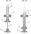
- FIG. 7 is a schematic view showing a state (a) of the shafts before the arm is lowered and a state (b) of the shafts after the arm is lowered in the dispensing mechanism according to the embodiment.
- the first shaft 26 and the upper shaft 41 are positioned upwardly. Then, when the motor 37 is driven, the first shaft 26 is lowered while sliding on the rotary ball spline 51. Here, the first shaft 26 is restricted to the position in the axial direction with respect to the upper shaft 41; therefore, when the first shaft 26 is lowered, the upper shaft 41 is also lowered together with the ball spline 43.
- the ball spline 43 is lowered sliding along the lower shaft 40. Then, as shown in Fig. 7(b) , the first shaft 26 and the upper shaft 41 move downwardly relatively to the lower shaft 40, the lower shaft 40 having a smaller diameter is gradually housed into the hollow upper shaft 41 having a larger diameter, and when the length of the second shaft is shortened, the downward operation of the arm is finished.
- the lower end of the lower shaft 40 is fixed to the base 24 together with the pulley 32, to restrict the position in the axial direction. Therefore, in the embodiment, no part of the second shaft is protruded from the bottom of the base 24 and the bottom space of the base 24 can be effectively availed.
- the embodiment adopts a structure in which the lower end of the second shaft is not lowered even when the upper end of the second shaft is lowered, in other words, in which the second shaft is not protruded from the bottom of the base 24; however, as far as a protruding portion can be smaller by shortening the length of the second shaft, some effect can be achieved.
- FIG. 8 is a schematic view showing a state (a) of the shaft before the arm is lowered and a state (b) of the shaft after the arm is lowered, in the dispensing mechanism of the comparison example.
- the first shaft 26 and the second shaft 31 are positioned upwardly. Thereafter, when the motor is driven, the first shaft 26 moves down while slidably moving the rotary ball spline 51.
- the first shaft 26 is restricted to the position in the axial direction with respect to the second shaft 31; therefore, when the first shaft 26 moves down, the second shaft 31 also moves down.
- the second shaft 31 moves down while slidably moving the ball spline 55 at the bottom of the base 24. Therefore, as shown in Fig. 8(b) , a part of the second shaft 31 is protruded from the bottom of the base 24 and the bottom space of the base 24 is restricted.
- the first embodiment is designed in that the outside arm 30 as the second arm is connected to the distal end of the inside arm 25 as the first arm and that each of the reagent probes 7a and 8a is mounted to the distal end of the outside arm 30. Therefore, it is possible to achieve the positioning at one stopping position with two degrees of freedom.
- arms each having one degree of freedom are vertically mounted in two stages and each arm can be rotated independently according to the first shaft and the second shaft.
- Fig. 9 is a perspective view of a dispensing mechanism according to the second embodiment.
- the dispensing mechanism according to this embodiment has two reagent probes 7a or 8a.
- the lower stage arm 49 as the first arm is rotated to position the reagent probe according to the first shaft 26, and the upper stage arm 50 as the second arm is rotated to position the reagent probe according to the second shaft (the upper shaft 41 and the lower shaft 40).
- the reagent probes 7a or 8a are respectively mounted to the distal ends of the arms, and the lower stage arm 49 and the upper stage arm 50 are vertically moved in the same way at the same time and can be rotated independently at the same time.
- the reagent probe 7a or 8a of the upper stage arm 50 is longer than the reagent probe 7a or 8a of the lower stage arm 49 so that the distal end of the reagent probe 7a or 8a of the upper stage arm 50 may be positioned at the same height as that of the lower stage arm 49.
- an automatic analyzer having a two degree of freedom arm that can set the two positions at the same time and that can dispense an object at the two positions at the same time. Further, since a single dispensing mechanism can dispense an object at two positions at the same time, the number of the dispensing mechanisms in the automatic analyzer can be reduced.
- the degree of freedom in the positioning can be increased.
- another arm is connected to each of the distal ends of the lower stage arm 49 and the upper stage arm 50, it is possible to position each probe not only with the two degrees of freedom but also at the two positions at the same time, hence to improve the accuracy of the stopping position.
- first and second embodiments are described in detail to explain the invention for easy understanding, and are not necessarily limited to those having all the described components. It is also possible to replace a part of the components of one embodiment with the other component of the other embodiment and to add a component of one embodiment to the components of the other embodiment. Further, it is also possible to add, delete, or replace some of the components of each embodiment to, from, or with the other components or component.
Landscapes
- Chemical & Material Sciences (AREA)
- Health & Medical Sciences (AREA)
- General Physics & Mathematics (AREA)
- Physics & Mathematics (AREA)
- Life Sciences & Earth Sciences (AREA)
- Analytical Chemistry (AREA)
- Biochemistry (AREA)
- General Health & Medical Sciences (AREA)
- Immunology (AREA)
- Pathology (AREA)
- Chemical Kinetics & Catalysis (AREA)
- Clinical Laboratory Science (AREA)
- Automatic Analysis And Handling Materials Therefor (AREA)
Applications Claiming Priority (2)
| Application Number | Priority Date | Filing Date | Title |
|---|---|---|---|
| JP2020028047 | 2020-02-21 | ||
| PCT/JP2021/001668 WO2021166522A1 (ja) | 2020-02-21 | 2021-01-19 | 自動分析装置 |
Publications (3)
| Publication Number | Publication Date |
|---|---|
| EP4109107A1 EP4109107A1 (en) | 2022-12-28 |
| EP4109107A4 EP4109107A4 (en) | 2024-02-21 |
| EP4109107B1 true EP4109107B1 (en) | 2025-06-25 |
Family
ID=77392117
Family Applications (1)
| Application Number | Title | Priority Date | Filing Date |
|---|---|---|---|
| EP21757567.9A Active EP4109107B1 (en) | 2020-02-21 | 2021-01-19 | Automatic analysis device |
Country Status (5)
| Country | Link |
|---|---|
| US (1) | US12436162B2 (https=) |
| EP (1) | EP4109107B1 (https=) |
| JP (1) | JP7350972B2 (https=) |
| CN (1) | CN115087872B (https=) |
| WO (1) | WO2021166522A1 (https=) |
Families Citing this family (5)
| Publication number | Priority date | Publication date | Assignee | Title |
|---|---|---|---|---|
| CN114689897B (zh) * | 2020-12-31 | 2025-08-05 | 深圳市新产业生物医学工程股份有限公司 | 试剂加注装置及具有其的样本分析仪 |
| WO2023076163A1 (en) * | 2021-10-29 | 2023-05-04 | Illumina, Inc. | Systems and related manifold assemblies |
| CN114384262B (zh) * | 2021-12-30 | 2025-09-26 | 深圳市新产业生物医学工程股份有限公司 | 吸液装置和样本分析仪 |
| WO2024036564A1 (zh) * | 2022-08-18 | 2024-02-22 | 创茂生技股份有限公司 | 旋转式移液装置 |
| JP2025094836A (ja) * | 2023-12-13 | 2025-06-25 | 日本電子株式会社 | 分注プローブ装置及び自動分析装置 |
Family Cites Families (21)
| Publication number | Priority date | Publication date | Assignee | Title |
|---|---|---|---|---|
| JPS5136546Y2 (https=) | 1973-03-12 | 1976-09-08 | ||
| JPH0334698Y2 (https=) * | 1985-10-09 | 1991-07-23 | ||
| JPS6365370A (ja) * | 1986-09-05 | 1988-03-23 | Nippon Tectron Co Ltd | サンプルピペツト装置 |
| JP2874328B2 (ja) * | 1990-10-29 | 1999-03-24 | 味の素株式会社 | 自動前処理装置 |
| JPH05126835A (ja) * | 1991-10-31 | 1993-05-21 | Shimadzu Corp | 分注装置 |
| JP3024375B2 (ja) * | 1992-07-31 | 2000-03-21 | 味の素株式会社 | 自動前処理装置 |
| JPH06109744A (ja) | 1992-09-25 | 1994-04-22 | Toshiba Corp | 自動化学分析装置の分注機構 |
| JP3481732B2 (ja) * | 1995-07-04 | 2003-12-22 | 株式会社東芝 | 自動分析装置 |
| JPH10253638A (ja) | 1997-03-14 | 1998-09-25 | Dainippon Seiki:Kk | 液体分注装置における液面検出方法および液面検出装置 |
| JP4293804B2 (ja) * | 2003-02-24 | 2009-07-08 | 日本フレックス工業株式会社 | 自立可能なステッキ |
| JP4221349B2 (ja) | 2004-09-17 | 2009-02-12 | 株式会社日立ハイテクノロジーズ | 自動分析装置 |
| JP4538478B2 (ja) * | 2007-08-31 | 2010-09-08 | 株式会社日立ハイテクノロジーズ | 自動分析装置 |
| JP2011027437A (ja) | 2009-07-21 | 2011-02-10 | Beckman Coulter Inc | 分注装置、分注装置の分注プローブ洗浄方法及び自動分析装置 |
| JP2011075356A (ja) * | 2009-09-30 | 2011-04-14 | Hitachi High-Technologies Corp | 検体処理システム |
| CN102967483B (zh) | 2012-11-15 | 2015-05-13 | 深圳市新产业生物医学工程股份有限公司 | 一种双节加样臂 |
| JP6153759B2 (ja) | 2013-04-10 | 2017-06-28 | 株式会社日立ハイテクノロジーズ | 自動分析装置 |
| CN203724054U (zh) | 2014-01-20 | 2014-07-23 | 嘉兴捷顺旅游制品有限公司 | 可收纳升降桶 |
| CN105092872A (zh) | 2014-04-17 | 2015-11-25 | 湖南长沙天地人生物科技有限公司 | 自动加样仪及其旋转升降组件 |
| CN204679513U (zh) * | 2015-02-27 | 2015-09-30 | 株式会社东芝 | 臂部防落装置及自动分析装置 |
| ITUB20152759A1 (it) * | 2015-08-03 | 2017-02-03 | Comau Spa | Robot per uso industriale |
| CN210005553U (zh) | 2019-06-12 | 2020-01-31 | 迈克医疗电子有限公司 | 试纸条旋转装置及干化学检测系统 |
-
2021
- 2021-01-19 WO PCT/JP2021/001668 patent/WO2021166522A1/ja not_active Ceased
- 2021-01-19 CN CN202180013988.3A patent/CN115087872B/zh active Active
- 2021-01-19 JP JP2022501706A patent/JP7350972B2/ja active Active
- 2021-01-19 EP EP21757567.9A patent/EP4109107B1/en active Active
- 2021-01-19 US US17/796,699 patent/US12436162B2/en active Active
Also Published As
| Publication number | Publication date |
|---|---|
| US12436162B2 (en) | 2025-10-07 |
| WO2021166522A1 (ja) | 2021-08-26 |
| US20230059337A1 (en) | 2023-02-23 |
| CN115087872A (zh) | 2022-09-20 |
| EP4109107A4 (en) | 2024-02-21 |
| JP7350972B2 (ja) | 2023-09-26 |
| EP4109107A1 (en) | 2022-12-28 |
| JPWO2021166522A1 (https=) | 2021-08-26 |
| CN115087872B (zh) | 2026-04-14 |
Similar Documents
| Publication | Publication Date | Title |
|---|---|---|
| EP4109107B1 (en) | Automatic analysis device | |
| US4906433A (en) | Automatic chemical analyzer | |
| JP2529015B2 (ja) | 異種の免疫学的テストに用いる分析ユニット | |
| CN104034908B (zh) | 一种新型全自动生化分析仪 | |
| JP6774151B2 (ja) | 自動分析装置 | |
| CN109358201A (zh) | 全自动化学发光免疫分析仪 | |
| CN103969459A (zh) | 一种全自动生化分析方法 | |
| CN102590539A (zh) | 分立式全自动生化分析仪 | |
| US10926232B2 (en) | Automatic analyzing apparatus | |
| US3853008A (en) | Liquid sample supply apparatus | |
| CN112213509B (zh) | 一种反应管自动加样系统 | |
| US20150168435A1 (en) | Automated Analyzer | |
| CN109212245A (zh) | 反应盘以及系统 | |
| FI64468B (fi) | Analysator | |
| JP7284801B2 (ja) | 試薬注加装置及びそれを備えるサンプル分析機器 | |
| JPH05126835A (ja) | 分注装置 | |
| CN207908534U (zh) | 一种具有搅拌功能的旋转加样臂装置 | |
| CN207379801U (zh) | 容器旋转装置及特定蛋白分析仪 | |
| CN215641321U (zh) | 试剂加注装置和样本分析仪 | |
| EP4685493A1 (en) | Piercing mechanism and automatic analysis device including same | |
| EP4571322A1 (en) | Dispensing probe device and automatic analysis device | |
| CN116008046B (zh) | 一种自动稀释加样装置 | |
| CN215641314U (zh) | 转运装置和样本分析仪 | |
| CN222497767U (zh) | 一种旋转上架装置及自动上管机 | |
| JPH1082789A (ja) | 自動分析装置 |
Legal Events
| Date | Code | Title | Description |
|---|---|---|---|
| STAA | Information on the status of an ep patent application or granted ep patent |
Free format text: STATUS: THE INTERNATIONAL PUBLICATION HAS BEEN MADE |
|
| PUAI | Public reference made under article 153(3) epc to a published international application that has entered the european phase |
Free format text: ORIGINAL CODE: 0009012 |
|
| STAA | Information on the status of an ep patent application or granted ep patent |
Free format text: STATUS: REQUEST FOR EXAMINATION WAS MADE |
|
| 17P | Request for examination filed |
Effective date: 20220722 |
|
| AK | Designated contracting states |
Kind code of ref document: A1 Designated state(s): AL AT BE BG CH CY CZ DE DK EE ES FI FR GB GR HR HU IE IS IT LI LT LU LV MC MK MT NL NO PL PT RO RS SE SI SK SM TR |
|
| DAV | Request for validation of the european patent (deleted) | ||
| DAX | Request for extension of the european patent (deleted) | ||
| A4 | Supplementary search report drawn up and despatched |
Effective date: 20240124 |
|
| RIC1 | Information provided on ipc code assigned before grant |
Ipc: G01N 35/10 20060101AFI20240118BHEP |
|
| GRAP | Despatch of communication of intention to grant a patent |
Free format text: ORIGINAL CODE: EPIDOSNIGR1 |
|
| STAA | Information on the status of an ep patent application or granted ep patent |
Free format text: STATUS: GRANT OF PATENT IS INTENDED |
|
| INTG | Intention to grant announced |
Effective date: 20250407 |
|
| GRAS | Grant fee paid |
Free format text: ORIGINAL CODE: EPIDOSNIGR3 |
|
| GRAA | (expected) grant |
Free format text: ORIGINAL CODE: 0009210 |
|
| STAA | Information on the status of an ep patent application or granted ep patent |
Free format text: STATUS: THE PATENT HAS BEEN GRANTED |
|
| AK | Designated contracting states |
Kind code of ref document: B1 Designated state(s): AL AT BE BG CH CY CZ DE DK EE ES FI FR GB GR HR HU IE IS IT LI LT LU LV MC MK MT NL NO PL PT RO RS SE SI SK SM TR |
|
| REG | Reference to a national code |
Ref country code: GB Ref legal event code: FG4D |
|
| REG | Reference to a national code |
Ref country code: CH Ref legal event code: EP |
|
| REG | Reference to a national code |
Ref country code: DE Ref legal event code: R096 Ref document number: 602021032909 Country of ref document: DE |
|
| REG | Reference to a national code |
Ref country code: CH Ref legal event code: EP |
|
| REG | Reference to a national code |
Ref country code: IE Ref legal event code: FG4D |
|
| PG25 | Lapsed in a contracting state [announced via postgrant information from national office to epo] |
Ref country code: FI Free format text: LAPSE BECAUSE OF FAILURE TO SUBMIT A TRANSLATION OF THE DESCRIPTION OR TO PAY THE FEE WITHIN THE PRESCRIBED TIME-LIMIT Effective date: 20250625 |
|
| REG | Reference to a national code |
Ref country code: LT Ref legal event code: MG9D |
|
| PG25 | Lapsed in a contracting state [announced via postgrant information from national office to epo] |
Ref country code: GR Free format text: LAPSE BECAUSE OF FAILURE TO SUBMIT A TRANSLATION OF THE DESCRIPTION OR TO PAY THE FEE WITHIN THE PRESCRIBED TIME-LIMIT Effective date: 20250926 Ref country code: NO Free format text: LAPSE BECAUSE OF FAILURE TO SUBMIT A TRANSLATION OF THE DESCRIPTION OR TO PAY THE FEE WITHIN THE PRESCRIBED TIME-LIMIT Effective date: 20250925 |
|
| PG25 | Lapsed in a contracting state [announced via postgrant information from national office to epo] |
Ref country code: BG Free format text: LAPSE BECAUSE OF FAILURE TO SUBMIT A TRANSLATION OF THE DESCRIPTION OR TO PAY THE FEE WITHIN THE PRESCRIBED TIME-LIMIT Effective date: 20250625 |
|
| PG25 | Lapsed in a contracting state [announced via postgrant information from national office to epo] |
Ref country code: HR Free format text: LAPSE BECAUSE OF FAILURE TO SUBMIT A TRANSLATION OF THE DESCRIPTION OR TO PAY THE FEE WITHIN THE PRESCRIBED TIME-LIMIT Effective date: 20250625 |
|
| PG25 | Lapsed in a contracting state [announced via postgrant information from national office to epo] |
Ref country code: RS Free format text: LAPSE BECAUSE OF FAILURE TO SUBMIT A TRANSLATION OF THE DESCRIPTION OR TO PAY THE FEE WITHIN THE PRESCRIBED TIME-LIMIT Effective date: 20250925 |
|
| PG25 | Lapsed in a contracting state [announced via postgrant information from national office to epo] |
Ref country code: LV Free format text: LAPSE BECAUSE OF FAILURE TO SUBMIT A TRANSLATION OF THE DESCRIPTION OR TO PAY THE FEE WITHIN THE PRESCRIBED TIME-LIMIT Effective date: 20250625 |
|
| REG | Reference to a national code |
Ref country code: NL Ref legal event code: MP Effective date: 20250625 |
|
| PG25 | Lapsed in a contracting state [announced via postgrant information from national office to epo] |
Ref country code: NL Free format text: LAPSE BECAUSE OF FAILURE TO SUBMIT A TRANSLATION OF THE DESCRIPTION OR TO PAY THE FEE WITHIN THE PRESCRIBED TIME-LIMIT Effective date: 20250625 |
|
| PG25 | Lapsed in a contracting state [announced via postgrant information from national office to epo] |
Ref country code: PT Free format text: LAPSE BECAUSE OF FAILURE TO SUBMIT A TRANSLATION OF THE DESCRIPTION OR TO PAY THE FEE WITHIN THE PRESCRIBED TIME-LIMIT Effective date: 20251027 |
|
| REG | Reference to a national code |
Ref country code: AT Ref legal event code: MK05 Ref document number: 1806960 Country of ref document: AT Kind code of ref document: T Effective date: 20250625 |
|
| PG25 | Lapsed in a contracting state [announced via postgrant information from national office to epo] |
Ref country code: IS Free format text: LAPSE BECAUSE OF FAILURE TO SUBMIT A TRANSLATION OF THE DESCRIPTION OR TO PAY THE FEE WITHIN THE PRESCRIBED TIME-LIMIT Effective date: 20251025 |
|
| PG25 | Lapsed in a contracting state [announced via postgrant information from national office to epo] |
Ref country code: AT Free format text: LAPSE BECAUSE OF FAILURE TO SUBMIT A TRANSLATION OF THE DESCRIPTION OR TO PAY THE FEE WITHIN THE PRESCRIBED TIME-LIMIT Effective date: 20250625 Ref country code: SM Free format text: LAPSE BECAUSE OF FAILURE TO SUBMIT A TRANSLATION OF THE DESCRIPTION OR TO PAY THE FEE WITHIN THE PRESCRIBED TIME-LIMIT Effective date: 20250625 |
|
| PG25 | Lapsed in a contracting state [announced via postgrant information from national office to epo] |
Ref country code: CZ Free format text: LAPSE BECAUSE OF FAILURE TO SUBMIT A TRANSLATION OF THE DESCRIPTION OR TO PAY THE FEE WITHIN THE PRESCRIBED TIME-LIMIT Effective date: 20250625 |
|
| PG25 | Lapsed in a contracting state [announced via postgrant information from national office to epo] |
Ref country code: PL Free format text: LAPSE BECAUSE OF FAILURE TO SUBMIT A TRANSLATION OF THE DESCRIPTION OR TO PAY THE FEE WITHIN THE PRESCRIBED TIME-LIMIT Effective date: 20250625 |
|
| PG25 | Lapsed in a contracting state [announced via postgrant information from national office to epo] |
Ref country code: EE Free format text: LAPSE BECAUSE OF FAILURE TO SUBMIT A TRANSLATION OF THE DESCRIPTION OR TO PAY THE FEE WITHIN THE PRESCRIBED TIME-LIMIT Effective date: 20250625 |
|
| PG25 | Lapsed in a contracting state [announced via postgrant information from national office to epo] |
Ref country code: SK Free format text: LAPSE BECAUSE OF FAILURE TO SUBMIT A TRANSLATION OF THE DESCRIPTION OR TO PAY THE FEE WITHIN THE PRESCRIBED TIME-LIMIT Effective date: 20250625 |
|
| PG25 | Lapsed in a contracting state [announced via postgrant information from national office to epo] |
Ref country code: ES Free format text: LAPSE BECAUSE OF FAILURE TO SUBMIT A TRANSLATION OF THE DESCRIPTION OR TO PAY THE FEE WITHIN THE PRESCRIBED TIME-LIMIT Effective date: 20250625 |
|
| PG25 | Lapsed in a contracting state [announced via postgrant information from national office to epo] |
Ref country code: DK Free format text: LAPSE BECAUSE OF FAILURE TO SUBMIT A TRANSLATION OF THE DESCRIPTION OR TO PAY THE FEE WITHIN THE PRESCRIBED TIME-LIMIT Effective date: 20250625 |
|
| PGFP | Annual fee paid to national office [announced via postgrant information from national office to epo] |
Ref country code: DE Payment date: 20260126 Year of fee payment: 6 |
|
| PG25 | Lapsed in a contracting state [announced via postgrant information from national office to epo] |
Ref country code: IT Free format text: LAPSE BECAUSE OF FAILURE TO SUBMIT A TRANSLATION OF THE DESCRIPTION OR TO PAY THE FEE WITHIN THE PRESCRIBED TIME-LIMIT Effective date: 20250625 |
|
| PGFP | Annual fee paid to national office [announced via postgrant information from national office to epo] |
Ref country code: FR Payment date: 20260223 Year of fee payment: 6 |
|
| PLBE | No opposition filed within time limit |
Free format text: ORIGINAL CODE: 0009261 |
|
| STAA | Information on the status of an ep patent application or granted ep patent |
Free format text: STATUS: NO OPPOSITION FILED WITHIN TIME LIMIT |