EP4108474B1 - Tire - Google Patents
Tire Download PDFInfo
- Publication number
- EP4108474B1 EP4108474B1 EP22176940.9A EP22176940A EP4108474B1 EP 4108474 B1 EP4108474 B1 EP 4108474B1 EP 22176940 A EP22176940 A EP 22176940A EP 4108474 B1 EP4108474 B1 EP 4108474B1
- Authority
- EP
- European Patent Office
- Prior art keywords
- belt
- tire
- band
- cord
- ply
- Prior art date
- Legal status (The legal status is an assumption and is not a legal conclusion. Google has not performed a legal analysis and makes no representation as to the accuracy of the status listed.)
- Active
Links
Images


Classifications
-
- B—PERFORMING OPERATIONS; TRANSPORTING
- B60—VEHICLES IN GENERAL
- B60C—VEHICLE TYRES; TYRE INFLATION; TYRE CHANGING; CONNECTING VALVES TO INFLATABLE ELASTIC BODIES IN GENERAL; DEVICES OR ARRANGEMENTS RELATED TO TYRES
- B60C9/00—Reinforcements or ply arrangement of pneumatic tyres
- B60C9/18—Structure or arrangement of belts or breakers, crown-reinforcing or cushioning layers
- B60C9/20—Structure or arrangement of belts or breakers, crown-reinforcing or cushioning layers built-up from rubberised plies each having all cords arranged substantially parallel
- B60C9/2003—Structure or arrangement of belts or breakers, crown-reinforcing or cushioning layers built-up from rubberised plies each having all cords arranged substantially parallel characterised by the materials of the belt cords
- B60C9/2009—Structure or arrangement of belts or breakers, crown-reinforcing or cushioning layers built-up from rubberised plies each having all cords arranged substantially parallel characterised by the materials of the belt cords comprising plies of different materials
-
- B—PERFORMING OPERATIONS; TRANSPORTING
- B60—VEHICLES IN GENERAL
- B60C—VEHICLE TYRES; TYRE INFLATION; TYRE CHANGING; CONNECTING VALVES TO INFLATABLE ELASTIC BODIES IN GENERAL; DEVICES OR ARRANGEMENTS RELATED TO TYRES
- B60C9/00—Reinforcements or ply arrangement of pneumatic tyres
- B60C9/0007—Reinforcements made of metallic elements, e.g. cords, yarns, filaments or fibres made from metal
- B60C2009/0014—Surface treatments of steel cords
-
- B—PERFORMING OPERATIONS; TRANSPORTING
- B60—VEHICLES IN GENERAL
- B60C—VEHICLE TYRES; TYRE INFLATION; TYRE CHANGING; CONNECTING VALVES TO INFLATABLE ELASTIC BODIES IN GENERAL; DEVICES OR ARRANGEMENTS RELATED TO TYRES
- B60C9/00—Reinforcements or ply arrangement of pneumatic tyres
- B60C9/18—Structure or arrangement of belts or breakers, crown-reinforcing or cushioning layers
- B60C9/20—Structure or arrangement of belts or breakers, crown-reinforcing or cushioning layers built-up from rubberised plies each having all cords arranged substantially parallel
- B60C2009/2048—Structure or arrangement of belts or breakers, crown-reinforcing or cushioning layers built-up from rubberised plies each having all cords arranged substantially parallel characterised by special physical properties of the belt plies
-
- B—PERFORMING OPERATIONS; TRANSPORTING
- B60—VEHICLES IN GENERAL
- B60C—VEHICLE TYRES; TYRE INFLATION; TYRE CHANGING; CONNECTING VALVES TO INFLATABLE ELASTIC BODIES IN GENERAL; DEVICES OR ARRANGEMENTS RELATED TO TYRES
- B60C9/00—Reinforcements or ply arrangement of pneumatic tyres
- B60C9/18—Structure or arrangement of belts or breakers, crown-reinforcing or cushioning layers
- B60C9/20—Structure or arrangement of belts or breakers, crown-reinforcing or cushioning layers built-up from rubberised plies each having all cords arranged substantially parallel
- B60C2009/2061—Physical properties or dimensions of the belt coating rubber
- B60C2009/2067—Thickness
-
- B—PERFORMING OPERATIONS; TRANSPORTING
- B60—VEHICLES IN GENERAL
- B60C—VEHICLE TYRES; TYRE INFLATION; TYRE CHANGING; CONNECTING VALVES TO INFLATABLE ELASTIC BODIES IN GENERAL; DEVICES OR ARRANGEMENTS RELATED TO TYRES
- B60C9/00—Reinforcements or ply arrangement of pneumatic tyres
- B60C9/18—Structure or arrangement of belts or breakers, crown-reinforcing or cushioning layers
- B60C9/20—Structure or arrangement of belts or breakers, crown-reinforcing or cushioning layers built-up from rubberised plies each having all cords arranged substantially parallel
- B60C2009/2074—Physical properties or dimension of the belt cord
- B60C2009/2077—Diameters of the cords; Linear density thereof
-
- B—PERFORMING OPERATIONS; TRANSPORTING
- B60—VEHICLES IN GENERAL
- B60C—VEHICLE TYRES; TYRE INFLATION; TYRE CHANGING; CONNECTING VALVES TO INFLATABLE ELASTIC BODIES IN GENERAL; DEVICES OR ARRANGEMENTS RELATED TO TYRES
- B60C9/00—Reinforcements or ply arrangement of pneumatic tyres
- B60C9/18—Structure or arrangement of belts or breakers, crown-reinforcing or cushioning layers
- B60C9/20—Structure or arrangement of belts or breakers, crown-reinforcing or cushioning layers built-up from rubberised plies each having all cords arranged substantially parallel
- B60C2009/2074—Physical properties or dimension of the belt cord
- B60C2009/2083—Density in width direction
-
- B—PERFORMING OPERATIONS; TRANSPORTING
- B60—VEHICLES IN GENERAL
- B60C—VEHICLE TYRES; TYRE INFLATION; TYRE CHANGING; CONNECTING VALVES TO INFLATABLE ELASTIC BODIES IN GENERAL; DEVICES OR ARRANGEMENTS RELATED TO TYRES
- B60C9/00—Reinforcements or ply arrangement of pneumatic tyres
- B60C9/18—Structure or arrangement of belts or breakers, crown-reinforcing or cushioning layers
- B60C9/20—Structure or arrangement of belts or breakers, crown-reinforcing or cushioning layers built-up from rubberised plies each having all cords arranged substantially parallel
- B60C2009/2074—Physical properties or dimension of the belt cord
- B60C2009/209—Tensile strength
-
- B—PERFORMING OPERATIONS; TRANSPORTING
- B60—VEHICLES IN GENERAL
- B60C—VEHICLE TYRES; TYRE INFLATION; TYRE CHANGING; CONNECTING VALVES TO INFLATABLE ELASTIC BODIES IN GENERAL; DEVICES OR ARRANGEMENTS RELATED TO TYRES
- B60C9/00—Reinforcements or ply arrangement of pneumatic tyres
- B60C9/18—Structure or arrangement of belts or breakers, crown-reinforcing or cushioning layers
- B60C9/20—Structure or arrangement of belts or breakers, crown-reinforcing or cushioning layers built-up from rubberised plies each having all cords arranged substantially parallel
- B60C9/22—Structure or arrangement of belts or breakers, crown-reinforcing or cushioning layers built-up from rubberised plies each having all cords arranged substantially parallel the plies being arranged with all cords disposed along the circumference of the tyre
- B60C2009/2214—Structure or arrangement of belts or breakers, crown-reinforcing or cushioning layers built-up from rubberised plies each having all cords arranged substantially parallel the plies being arranged with all cords disposed along the circumference of the tyre characterised by the materials of the zero degree ply cords
-
- B—PERFORMING OPERATIONS; TRANSPORTING
- B60—VEHICLES IN GENERAL
- B60C—VEHICLE TYRES; TYRE INFLATION; TYRE CHANGING; CONNECTING VALVES TO INFLATABLE ELASTIC BODIES IN GENERAL; DEVICES OR ARRANGEMENTS RELATED TO TYRES
- B60C9/00—Reinforcements or ply arrangement of pneumatic tyres
- B60C9/18—Structure or arrangement of belts or breakers, crown-reinforcing or cushioning layers
- B60C9/20—Structure or arrangement of belts or breakers, crown-reinforcing or cushioning layers built-up from rubberised plies each having all cords arranged substantially parallel
- B60C9/22—Structure or arrangement of belts or breakers, crown-reinforcing or cushioning layers built-up from rubberised plies each having all cords arranged substantially parallel the plies being arranged with all cords disposed along the circumference of the tyre
- B60C2009/2238—Physical properties or dimensions of the ply coating rubber
- B60C2009/2247—Thickness
-
- B—PERFORMING OPERATIONS; TRANSPORTING
- B60—VEHICLES IN GENERAL
- B60C—VEHICLE TYRES; TYRE INFLATION; TYRE CHANGING; CONNECTING VALVES TO INFLATABLE ELASTIC BODIES IN GENERAL; DEVICES OR ARRANGEMENTS RELATED TO TYRES
- B60C9/00—Reinforcements or ply arrangement of pneumatic tyres
- B60C9/18—Structure or arrangement of belts or breakers, crown-reinforcing or cushioning layers
- B60C9/20—Structure or arrangement of belts or breakers, crown-reinforcing or cushioning layers built-up from rubberised plies each having all cords arranged substantially parallel
- B60C9/22—Structure or arrangement of belts or breakers, crown-reinforcing or cushioning layers built-up from rubberised plies each having all cords arranged substantially parallel the plies being arranged with all cords disposed along the circumference of the tyre
- B60C2009/2252—Physical properties or dimension of the zero degree ply cords
- B60C2009/2257—Diameters of the cords; Linear density thereof
Definitions
- the present invention relates to a tire having a belt layer, a band, and the like.
- Japanese Laid-Open Patent Publication No. 2019-177838 suggests a tire in which a belt formed of two or more layers includes cords and a gauge between the cords of the two adjacent layers is specified to allow achievement of both noise performance and fuel economy.
- the present invention has been made in view of the aforementioned circumstances, and a main object of the present invention is to provide a tire that can achieve both durability and ride comfort during high-speed running.
- the present invention is directed to a tire including a belt layer and a band layer.
- the belt layer includes at least one belt ply.
- the belt ply includes a belt cord formed of a single steel cord such that 60 to 140 belt cords are arranged per ply width of 5 cm.
- the band layer includes at least one band ply.
- the band ply includes a band cord disposed at an angle of not greater than 5° relative to a tire circumferential direction.
- the band cord has a flattened cross-section orthogonal to a longitudinal direction of the band cord.
- an aspect ratio of the band cord is preferably 1.05 to 1.25.
- the band cord is preferably formed of a heat-shrinkable organic fiber.
- the organic fiber is preferably nylon.
- the belt ply and the band ply satisfy the following expression (1), [Math. 1] 0.30 ⁇ G 1 + G 2 ⁇ d 1 + d 2 G 1 + G 2 + d 1 + d 2 ⁇ 0.45 in which
- a product of a strength (N) per the one belt cord and a number (number of the belt cords) of the belt cords arranged per ply width of 5 cm is preferably 12000 to 22000 (N ⁇ the number of the belt cords).
- the belt cord preferably has, on a surface, a ternary alloy-plated layer formed of copper (Cu), zinc (Zn), and cobalt (Co).
- a mass of the copper (Cu) is less than 65%
- a mass of the zinc (Zn) is less than 35%
- a mass of the cobalt (Co) is less than 10%.
- the tire of the present invention includes the belt layer and the band layer.
- the belt layer includes at least one belt ply.
- the belt ply includes the belt cord formed of a single steel cord such that 60 to 140 belt cords are arranged per ply width of 5 cm.
- the band layer includes at least one band ply.
- the band ply includes the band cord disposed at an angle of not greater than 5° relative to the tire circumferential direction.
- the band cord has a flattened cross-section orthogonal to the longitudinal direction of the band cord.
- the belt cords are arranged at a high density, a holding force is high, growth of the outer diameter of the tread portion during high-speed running can be inhibited, and durability during high-speed running can be enhanced.
- the band cord is flattened, the thickness of rubber between the belt cord and the band cord can be increased, stiffness of the tread portion is inhibited from being excessively enhanced due to the belt cords arranged at a high density, and ride comfort during high-speed running can be enhanced. Therefore, the tire of the present invention allows both durability and ride comfort during high-speed running to be achieved.
- FIG. 1 is a tire meridian cross-sectional view of a tire 1 of the present embodiment including a rotation axis in a normal state.
- the "normal state” represents a state where, in a case where the tire 1 is a pneumatic tire, the tire 1 is mounted on a normal rim and is adjusted to have a normal internal pressure, and no load is applied to the tire.
- dimensions and the like of the components of the tire 1 are represented by values measured in the normal state.
- the "normal rim” represents a rim that is defined for each tire by the standard, and is, for example, “standard rim” in the JATMA standard, "Design Rim” in the TRA standard, or “Measuring Rim” in the ETRTO standard.
- the "normal rim” represents a rim having the smallest rim width in rims on which the tire can be mounted, and which do not cause air leakage and have the smallest rim diameter.
- the "normal internal pressure” represents an air pressure that is defined for each tire by each standard, and is “maximum air pressure” in the JATMA standard, the maximum value recited in the table "TIRE LOAD LIMITS AT VARIOUS COLD INFLATION PRESSURES" in the TRA standard, or "INFLATION PRESSURE” in the ETRTO standard.
- the "normal internal pressure” represents an air pressure defined for each tire by manufacturers or the like.
- the tire 1 of the present embodiment is preferably used as a tire for a passenger car.
- the tire for a passenger car represents a pneumatic rubber tire which is produced on the assumption that the tire is mounted to a four-wheel traveling automobile and for which the normal load is not higher than 1000 kg.
- the tire for a passenger car is not particularly limited as long as the normal load is not higher than 1000 kg.
- the tire for a passenger car is preferably applied to a tire for which the normal load is 900 kg, more preferably applied to a tire for which the normal load is 750 kg, and even more preferably applied to a tire for which the normal load is 700 kg.
- the above-described normal internal pressure is 250 kPa.
- the "normal load” represents a load that is defined by a standard, in a standard system including the standard on which the tire 1 is based, for each tire, and is the "maximum load capacity" in the JATMA standard, the maximum value recited in the table "TIRE LOAD LIMITS AT VARIOUS COLD INFLATION PRESSURES" in the TRA standard, or the "LOAD CAPACITY” in the ETRTO standard.
- the "normal load” represents a load defined for each tire by manufactures or the like.
- the tire 1 is not limited to a tire for a passenger car, and can be applied to, for example, a heavy-duty tire, a tire for a motorcycle, a tire for a racing vehicle, and the like.
- the tire 1 having a belt layer 7 and a band layer 9 described below can be applied to various tires including, for example, tires that are made of resin by using thermoplastic elastomer and non-pneumatic tires the insides of which are not filled with pressurized air.
- the tire 1 of the present embodiment includes an annularly extending tread portion 2, a pair of sidewall portions 3 extending on both sides of the tread portion 2, and a pair of bead portions 4 extending so as to be continuous with the sidewall portions 3.
- the tire 1 of the present embodiment has a toroidal carcass 6 extending on and between bead cores 5 of the pair of bead portions 4, and the belt layer 7 disposed tire-radially outward of the carcass 6 and inward of the tread portion 2 in a tire radial direction a.
- the tread portion 2 is preferably formed of an elastomer layer having at least one layer.
- the tread portion 2 may have two or more layers of the elastomer layer stacked in the tire radial direction a, and may have a plurality of elastomer layers disposed in the tire axial direction.
- circumferential grooves extending in the tire circumferential direction, lateral grooves extending in the tire axial direction, sipes each having a groove width of not greater than 2 mm, and the like may be disposed as appropriate.
- the circumferential grooves include grooves that linearly extend or grooves extending so as to zigzag.
- a profile of an outer surface 2a of the tread portion 2 is, for example, formed by a single arc or by combining arcs having a plurality of curvatures.
- the elastomer layer of the tread portion 2 is formed of, for example, isoprene-based rubber such as natural rubber and isoprene rubber, or diene-based rubber such as butadiene rubber, styrene-butadiene rubber, styrene-isoprene-butadiene rubber, chloroprene rubber, acrylonitrile butadiene rubber, and isobutylene-isoprene-rubber.
- isoprene-based rubber such as natural rubber and isoprene rubber
- diene-based rubber such as butadiene rubber, styrene-butadiene rubber, styrene-isoprene-butadiene rubber, chloroprene rubber, acrylonitrile butadiene rubber, and isobutylene-isoprene-rubber.
- the sidewall portion 3 is preferably formed of an elastomer layer having at least one layer.
- two or more layers of the elastomer layer may be stacked in the tire axial direction, or a plurality of the elastomer layers may be disposed in the tire radial direction a.
- the elastomer layer of the sidewall portion 3 may be, for example, formed of the same component as that of the elastomer layer of the tread portion 2 or may be formed of a different component.
- a boundary face between the elastomer layer of the tread portion 2 and the elastomer layer of the sidewall portion 3 is, for example, formed such that the tire-axially outer end is disposed outward of the tire-axially inner end in the tire radial direction a.
- the boundary face between the elastomer layer of the tread portion 2 and the elastomer layer of the sidewall portion 3 may be, for example, formed such that the tire-axially outer end is disposed inward of the tire-axially inner end in the tire radial direction a.
- the carcass 6 includes at least one carcass ply 6A.
- the carcass 6 includes one carcass ply 6A.
- the carcass ply 6A is formed of, for example, an elastomer layer including a carcass cord (not shown) disposed at an angle of 75 to 90° relative to the tire circumferential direction.
- a carcass cord for example, an organic fiber cord formed of aromatic polyamide (aramid), rayon, polyester, or the like can be adopted.
- aromatic polyamide rayon, polyester, or the like
- the carcass ply 6A includes, for example, a body portion 6a extending from the tread portion 2 through the sidewall portions 3 to the bead cores 5 of the bead portions 4, and turned-up portions 6b that are continuous with the body portion 6a and are turned up around the bead cores 5 from the inner side toward the outer side in the tire axial direction.
- an outer end of the turned-up portion 6b in the tire radial direction a may extend to the belt layer 7.
- a bead apex 8 is disposed between the body portion 6a and each turned-up portion 6b of the carcass ply 6A so as to extend outwardly from the bead core 5 in the tire radial direction.
- the bead apex 8 is formed of, for example, an elastomer layer.
- bead reinforcing layers may be disposed outward of the turned-up portions 6b of the carcass 6 in the tire axial direction.
- the bead reinforcing layer may be formed of, for example, an elastomer layer having the same component as that of the bead apex 8, or may be formed of an elastomer layer having a different component.
- chafers may be disposed outward of the turned-up portions 6b of the carcass 6 in the tire axial direction.
- the chafer is preferably disposed outward of the bead reinforcing layer in the tire axial direction.
- the belt layer 7 includes at least one belt ply and preferably includes two or more belt plies.
- the belt layer 7 includes two belt plies 7A, 7B.
- the two belt plies 7A, 7B include, for example, a first belt ply 7A disposed on the outer side in the tire radial direction and a second belt ply 7B disposed inward of the first belt ply 7A.
- the belt layer 7 having such a structure enhances a holding force and can enhance durability of the tire 1 during high-speed running.
- the band layer 9 is disposed outward of the belt layer 7 in the tire radial direction a and inward of the tread portion 2 in the tire radial direction a.
- the band layer 9 includes at least one band ply.
- the band layer 9 includes one band ply 9A.
- the band layer 9 having such a structure enhances holdability of the tread portion 2 and can further enhance durability of the tire 1 also during high-speed running.
- the tire 1 of the present embodiment has an inner liner 10 disposed inward of the carcass 6.
- the inner liner 10 is preferably formed of an air-impermeable elastomer layer.
- the elastomer layer of the inner liner 10 is formed of, for example, isobutylene-isoprene-rubber or halogenated isobutylene-isoprene-rubber.
- the inner liner 10 having such a structure is suitable for maintaining air pressure to which the tire 1 is inflated.
- FIG. 2 is a cross-sectional view of the belt layer 7 and the band layer 9 according to the present embodiment.
- the belt plies 7A and 7B of the belt layer 7 each include a belt cord 7a formed of a single steel cord and an elastomer composition 7G for covering the belt cord 7a.
- the belt plies 7A, 7B having such a structure are expanded less easily than a twisted cord, a holding force can be enhanced, and durability of the tire 1 during high-speed running can be enhanced.
- the elastomer composition 7G of the belt plies 7A and 7B exhibits rubber elasticity.
- the elastomer composition 7G include a rubber composition and a thermoplastic elastomer composition.
- examples of the rubber component include isoprene-based rubber, butadiene-based rubber, styrene-butadiene rubber, nitrile rubber, and isobutylene-isoprene-rubber.
- the elastomer composition 7G is a thermoplastic elastomer composition
- examples of the elastomer include thermoplastic polyurethane, and block copolymers such as styrene-butadiene block copolymer and styrene-ethylene-butylene-styrene block copolymer.
- the belt cord 7a is a plated or ternary alloy-plated one.
- plating treatment for example, plating treatment using zinc, copper, and the like can be performed.
- the belt cord 7a having, on the surface, a ternary alloy-plated layer formed of copper (Cu), zinc (Zn), and cobalt (Co) is preferably formed.
- a composition mass ratio of the ternary alloy-plated layer preferably, a mass of the copper (Cu) is less than 65%, a mass of the zinc (Zn) is less than 35%, and a mass of the cobalt (Co) is less than 10%.
- the belt cord 7a having such a structure has good adhesiveness to the elastomer composition 7G, and the belt cord 7a and the elastomer composition 7G can cooperate to generate a stress also during high-speed running, and durability of the tire 1 during high-speed running can be enhanced.
- the cross-section orthogonal to the longitudinal direction of the belt cord 7a is flattened.
- the flattened means that an aspect ratio between the major axis and the minor axis of the cross-section is not less than 1.05.
- the belt cord 7a may have, for example, a round cross-section.
- the round means that the aspect ratio of the cross-section is less than 1.05.
- the belt cord 7a is, for example, disposed at an angle of 10 to 30° relative to the tire circumferential direction.
- the belt cord 7a of the first belt ply 7A and the belt cord 7a of the second belt ply 7B are preferably inclined in the opposite directions relative to the tire circumferential direction.
- the belt layer 7 having such a structure enhances a holding force of the tread portion 2 in a well-balanced manner, and can enhance durability of the tire 1 during high-speed running.
- the angle of the belt cord 7a represents an angle in the tire 1 in the normal state, and can be confirmed by, for example, partially peeling the tread portion 2.
- belt cords 7a are preferably arranged per ply width of 5 cm.
- the number n1 of the belt cords 7a arranged per ply width of 5 cm represents the number of the belt cords 7a arranged per ply width of 5 cm in the direction orthogonal to the longitudinal direction of the belt cord 7a.
- the number n1 of the arranged belt cords 7a can be, for example, obtained by measurement in a range of the belt ply 7A, 7B including a tire equator C.
- the number n1 of the belt cords 7a arranged per ply width of 5 cm is not less than 60, a holding force of the tread portion 2 can be enhanced, and durability of the tire 1 during high-speed running can be enhanced.
- the number n1 of the arranged belt cords 7a is more preferably not less than 70 and even more preferably not less than 80.
- the number n1 of the belt cords 7a arranged per ply width of 5 cm is not greater than 140, stiffness of the tread portion 2 is inhibited from being excessively enhanced, and ride comfort exhibited by the tire 1 during high-speed running can be enhanced.
- the number n1 of the arranged belt cords 7a is more preferably not greater than 130 and even more preferably not greater than 120.
- the belt cords 7a are arranged at a high density, a holding force is high, growth of the outer diameter of the tread portion 2 during high-speed running can be inhibited, and durability during high-speed running can be enhanced.
- a diameter d1 of the belt cord 7a in the tire radial direction a is preferably not greater than 0.2 mm.
- the belt cord 7a having such a structure since the diameter d1 of the belt cord 7a in the tire radial direction a is small, stiffness in the tire radial direction a can be reduced and ride comfort exhibited by the tire 1 during high-speed running can be enhanced.
- the diameter d1 of the belt cord 7a in the tire radial direction a is more preferably not greater than 0.17 mm.
- the lower limit value of the diameter d1 of the belt cord 7a is, but is not particularly limited to, preferably not less than 0.1 mm and more preferably not less than 0.12 mm.
- the diameter d1 of the belt cord 7a in the tire radial direction a is a diameter along the tire radial direction a.
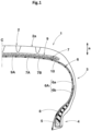
- FIG. 3 is a schematic diagram illustrating the belt cord 7a.
- the belt cord 7a having a flattened cross-section is inclined relative to the tire radial direction a
- one axis, of a minor axis Sd and a major axis Ld of the belt cord 7a having the flattened cross-section, having a smaller angle relative to the tire radial direction a is set as the diameter d1 in the tire radial direction a.
- an angle ⁇ 1 of the minor axis Sd direction relative to the tire radial direction a is less than an angle ⁇ 2 of the major axis Ld direction relative thereto, so that the minor axis Sd is set as the diameter d1 in the tire radial direction a.
- a product (d1 ⁇ n1) of the diameter d1 (mm) of the belt cord 7a and the number n1 (the number of the belt cords) of the belt cords 7a arranged per ply width of 5 cm is preferably not greater than 25 (mm ⁇ the number of the belt cords).
- This product (d1 ⁇ n1) represents a proportion of the belt cords 7a relative to the width direction of the belt ply 7A, 7B and represents an index for an interval between the belt cords 7a adjacent to each other in the width direction.
- the product (d1 ⁇ n1) is not greater than 25 (mm ⁇ the number of the belt cords), stiffness of the tread portion 2 is inhibited from being excessively enhanced, and ride comfort exhibited by the tire 1 during high-speed running can be enhanced.
- the product (d1 ⁇ n1) is more preferably not greater than 23 (mm ⁇ the number of the belt cords) and even more preferably not greater than 20 (mm ⁇ the number of the belt cords).
- the product (d1 ⁇ n1) of the diameter d1 (mm) of the belt cord 7a and the number n1 (the number of the belt cords) of the belt cords 7a arranged per ply width of 5 cm is preferably not less than 10 (mm ⁇ the number of the belt cords).
- the product (d1 ⁇ n1) is not less than 10 (mm ⁇ the number of the belt cords)
- holdability of the tread portion 2 is enhanced and durability of the tire 1 during high-speed running can be enhanced.
- the product (d1 ⁇ n1) is more preferably not less than 12 (mm ⁇ the number of the belt cords) and even more preferably not less than 15 (mm ⁇ the number of the belt cords).
- a product (s1 ⁇ n1) of a strength s1 (N) per one belt cord 7a and the number n1 (the number of the belt cords) of the belt cords 7a arranged per ply width of 5 cm is preferably 12000 to 22000 (N ⁇ the number of the belt cords).
- the strength s1 (N) per one belt cord 7a represents a tensile force at break of one belt cord 7a at 25°C.
- the product (s1 ⁇ n1) is not less than 12000 (N ⁇ the number of the belt cords)
- the holdability of the tread portion 2 is enhanced and durability of the tire 1 during high-speed running can be enhanced.
- the product (s1 ⁇ n1) is more preferably not less than 13500 (N ⁇ the number of the belt cords) and even more preferably not less than 15000 (N ⁇ the number of the belt cords).
- the product (s1 ⁇ n1) is not greater than 22000 (N the number of the belt cords), stiffness of the tread portion 2 is inhibited from being excessively enhanced, and ride comfort exhibited by the tire 1 during high-speed running can be enhanced.
- the product (s1 ⁇ n1) is more preferably not greater than 21000 (N ⁇ the number of the belt cords) and even more preferably not greater than 20000 (N ⁇ the number of the belt cords).
- the band ply 9A includes a band cord 9a disposed at an angle of not greater than 5° relative to the tire circumferential direction and an elastomer composition 9G for covering the band cord 9a.
- the elastomer composition 9G of the band ply 9A preferably exhibits rubber elasticity like the elastomer composition 7G of the belt plies 7A, 7B.
- the elastomer composition 9G may be the same as the elastomer composition 7G.
- the cross-section orthogonal to the longitudinal direction of the band cord 9a is flattened.
- a thickness of rubber can be increased between the belt cord 7a and the band cord 9a, stiffness of the tread portion 2 is inhibited from being excessively enhanced due to the belt cords 7a arranged at a high density, and ride comfort during high-speed running can be enhanced. Therefore, the tire 1 of the present embodiment can exhibit both durability and ride comfort during high-speed running.
- an aspect ratio of the band cord 9a is 1.05 to 1.25.
- the aspect ratio of the band cord 9a is more preferably not less than 1.08 and even more preferably not less than 1.10.
- the aspect ratio of the band cord 9a is not greater than 1.25, excessive change between stiffness of the tread portion 2 in the tire axial direction and that in the tire radial direction a is inhibited, and durability of the tire 1 during high-speed running can be enhanced. From such a viewpoint, the aspect ratio of the band cord 9a is more preferably not greater than 1.22 and even more preferably not greater than 1.20.
- the band cord 9a is formed of, for example, an organic fiber.
- the band cord 9a is formed of a heat-shrinkable organic fiber.
- the band cord 9a having such a structure can enhance a holding force of the tread portion 2 by heat generation during high-speed running, whereby durability of the tire 1 during high-speed running can be further enhanced.
- the heat-shrinkable organic fiber examples include aliphatic polyamides (nylon), polyethylene, and polyester.
- the organic fiber is nylon.
- Nylon has excellent strength and heat-shrinkability, and is suitable for enhancing durability of the tire 1 during high-speed running.
- a diameter d2 of the band cord 9a in the tire radial direction a is preferably 0.40 to 0.70 mm.
- the diameter d2 of the band cord 9a in the tire radial direction a is a diameter along the tire radial direction a.
- the diameter d2 of the band cord 9a in the tire radial direction a is not less than 0.40 mm, the holdability of the tread portion 2 is assuredly enhanced and both durability of the tire 1 and ride comfort exhibited by the tire 1 during high-speed running can be achieved.
- the diameter d2 of the band cord 9a is more preferably not less than 0.50 mm and even more preferably not less than 0.55 mm.
- the diameter d2 of the band cord 9a in the tire radial direction a is not greater than 0.70 mm, the thickness of the tread portion 2 is inhibited from being increased and ride comfort exhibited by the tire 1 during high-speed running can be enhanced. From such a viewpoint, the diameter d2 of the band cord 9a is more preferably not greater than 0.65 mm.
- FIG. 4 is a schematic diagram illustrating the band cord 9a.
- one axis, of a minor axis Sd and a major axis Ld of the band cord 9a having the flattened cross-section, having a smaller angle relative to the tire radial direction a is set as the diameter d2 in the tire radial direction a.
- an angle ⁇ 3 of the minor axis Sd direction relative to the tire radial direction a is less than an angle ⁇ 4 of the major axis Ld direction relative thereto. Therefore, the minor axis Sd is set as the diameter d2 in the tire radial direction a.
- band cords 9a are preferably arranged per ply width of 5 cm.
- the number n2 of the band cords 9a arranged per ply width of 5 cm represents the number of the band cords 9a arranged per ply width of 5 cm in the direction orthogonal to the longitudinal direction of the band cord 9a.
- the number n2 of the band cords 9a arranged per ply width of 5 cm is not less than 35, the holdability of the tread portion 2 is assuredly enhanced and durability of the tire 1 during high-speed running can be enhanced.
- the number n2 of the arranged band cords 9a is more preferably not less than 40 and even more preferably not less than 45.
- the number n2 of the band cords 9a arranged per ply width of 5 cm is not greater than 65, stiffness of the tread portion 2 is inhibited from being excessively enhanced and ride comfort exhibited by the tire 1 during high-speed running can be enhanced.
- the number n2 of the arranged band cords 9a is more preferably not greater than 60 and even more preferably not greater than 55.
- a product (d2 ⁇ n2) of the diameter d2 (mm) of the band cord 9a in the tire radial direction a and the number n2 (the number of the band cords) of the band cords 9a arranged per ply width of 5 cm is preferably 15 to 45.
- This product (d2 ⁇ n2) represents a proportion of the band cords 9a relative to the width direction of the band ply 9A and represents an index for an interval between the adjacent band cords 9a.
- the product (d2 ⁇ n2) is not less than 15, the holdability of the tread portion 2 is assuredly enhanced and durability of the tire 1 during high-speed running can be enhanced.
- the product (d2 ⁇ n2) is more preferably not less than 20.
- the product (d2 ⁇ n2) is not greater than 45, separation caused by a small interval between the band cords 9a is inhibited and durability of the tire 1 can be enhanced.
- the product (d2 ⁇ n2) is more preferably not greater than 40.
- the belt ply 7A and the band ply 9A satisfy the following expression (1), [Math. 1] 0.30 ⁇ G 1 + G 2 ⁇ d 1 + d 2 G 1 + G 2 + d 1 + d 2 ⁇ 0.45 where
- the belt ply 7A and the band ply 9A having such a structure allow a thickness of rubber between the belt cord 7a and the band cord 9a adjacent to each other in the tire radial direction a to be appropriately maintained and allow both durability of the tire 1 and ride comfort exhibited by the tire 1 during high-speed running to be achieved.
- the thickness G1 of the belt ply 7A is the maximum thickness, in the tire radial direction a, of the elastomer composition 7G of the belt ply 7A.
- the thickness G2 of the band ply 9A is the maximum thickness, in the tire radial direction a, of the elastomer composition 9G of the band ply 9A.
- the thickness G1 of the belt ply 7A and the thickness G2 of the band ply 9A can be, for example, confirmed from the cross-section of the tread portion 2.
- the belt ply 7A may be, for example, defined by setting, as boundaries, a mid-position between the belt cords 7a adjacent to each other in the tire radial direction a and a mid-position between the belt cord 7a and the band cord 9a.
- Tires having the basic structure shown in FIG. 1 were produced as test tires based on the specifications indicated in Table 1 and Table 2.
- the tires produced as the test tires were tested for durability and ride comfort during high-speed running.
- the common specifications and test methods were as follows.
- a front-wheel-drive medium-size passenger car in which the test tires having an air pressure adjusted to 230 kPa were mounted to all wheels was used as a test vehicle.
- a test driver made sensory evaluation for ride comfort by five-point evaluation with 5 being the best score.
- the same test was performed by 20 test drivers, and the total point was calculated. The result is indicated as an index with the total point in comparative example 1 being 100. The greater the value is, the more excellent ride comfort during high-speed running is.
- the test tire having an air pressure adjusted to 150 kPa was thermally degraded for 168 hours in an environment in which the temperature was 80°C, and was thereafter mounted to a drum tester, and running with the tire was performed under a load of 6.96 kN at 80 km/hour, and a distance was measured until occurrence of air leakage or deformation of the sidewall portion.
- the result is indicated as an index with the result of comparative example 1 being 100. The greater the value is, the more excellent durability during high-speed running is.
- the tires of the examples exhibited excellent durability and ride comfort during high-speed running as compared with the tires of the comparative examples, and the overall performance determined as the total of values of the respective performances was good in the tires of the examples, so that it was confirmed that both durability and ride comfort during high-speed running were able to be achieved.
Landscapes
- Engineering & Computer Science (AREA)
- Mechanical Engineering (AREA)
- Tires In General (AREA)
- Ropes Or Cables (AREA)
- Yarns And Mechanical Finishing Of Yarns Or Ropes (AREA)
Description
- The present invention relates to a tire having a belt layer, a band, and the like.
- To date, a tire having a belt layer and a band layer disposed inward of a tread portion in the tire radial direction has been known. For example,
Japanese Laid-Open Patent Publication No. 2019-177838 - However, in recent years, the tire disclosed in
Japanese Laid-Open Patent Publication No. 2019-177838
US 2020/0298623 A1 discloses a tire comprising the features according to the preamble ofclaim 1.
JP H04 66305 A - The present invention has been made in view of the aforementioned circumstances, and a main object of the present invention is to provide a tire that can achieve both durability and ride comfort during high-speed running.
- The present invention is directed to a tire including a belt layer and a band layer. The belt layer includes at least one belt ply. The belt ply includes a belt cord formed of a single steel cord such that 60 to 140 belt cords are arranged per ply width of 5 cm. The band layer includes at least one band ply. The band ply includes a band cord disposed at an angle of not greater than 5° relative to a tire circumferential direction. The band cord has a flattened cross-section orthogonal to a longitudinal direction of the band cord.
- In the tire of the present invention, an aspect ratio of the band cord is preferably 1.05 to 1.25.
- In the tire of the present invention, the band cord is preferably formed of a heat-shrinkable organic fiber.
- In the tire of the present invention, the organic fiber is preferably nylon.
- In the tire of the present invention, the belt ply and the band ply satisfy the following expression (1),
[Math. 1]
- G1: a thickness, in a tire radial direction, of the belt ply that is in contact with the band ply,
- G2: a thickness, in the tire radial direction, of the band ply that is in contact with the belt ply,
- d1: a diameter of the belt cord in the tire radial direction,
- d2: a diameter of the band cord in the tire radial direction.
- In the tire of the present invention, in the belt ply, a product of a strength (N) per the one belt cord and a number (number of the belt cords) of the belt cords arranged per ply width of 5 cm is preferably 12000 to 22000 (N·the number of the belt cords).
- In the tire of the present invention, the belt cord preferably has, on a surface, a ternary alloy-plated layer formed of copper (Cu), zinc (Zn), and cobalt (Co).
- In the tire of the present invention, as a composition mass ratio of the ternary alloy-plated layer, preferably, a mass of the copper (Cu) is less than 65%, a mass of the zinc (Zn) is less than 35%, and a mass of the cobalt (Co) is less than 10%.
- The tire of the present invention includes the belt layer and the band layer. The belt layer includes at least one belt ply. The belt ply includes the belt cord formed of a single steel cord such that 60 to 140 belt cords are arranged per ply width of 5 cm. The band layer includes at least one band ply. The band ply includes the band cord disposed at an angle of not greater than 5° relative to the tire circumferential direction. The band cord has a flattened cross-section orthogonal to the longitudinal direction of the band cord.
- In such a tire, since the belt cords are arranged at a high density, a holding force is high, growth of the outer diameter of the tread portion during high-speed running can be inhibited, and durability during high-speed running can be enhanced. In the tire, since the band cord is flattened, the thickness of rubber between the belt cord and the band cord can be increased, stiffness of the tread portion is inhibited from being excessively enhanced due to the belt cords arranged at a high density, and ride comfort during high-speed running can be enhanced. Therefore, the tire of the present invention allows both durability and ride comfort during high-speed running to be achieved.
-
-
FIG. 1 is a cross-sectional view of a tire according to one embodiment of the present invention; -
FIG. 2 is a cross-sectional view of a belt layer and a band layer according to the present embodiment; -
FIG. 3 is a schematic diagram illustrating a belt cord; and -
FIG. 4 is a schematic diagram illustrating a band cord. - An embodiment of the present invention will be described below in detail with reference to the drawings.
-
FIG. 1 is a tire meridian cross-sectional view of atire 1 of the present embodiment including a rotation axis in a normal state. The "normal state" represents a state where, in a case where thetire 1 is a pneumatic tire, thetire 1 is mounted on a normal rim and is adjusted to have a normal internal pressure, and no load is applied to the tire. Hereinafter, unless otherwise specified, dimensions and the like of the components of thetire 1 are represented by values measured in the normal state. - When a standard system including a standard on which the
tire 1 is based is provided, the "normal rim" represents a rim that is defined for each tire by the standard, and is, for example, "standard rim" in the JATMA standard, "Design Rim" in the TRA standard, or "Measuring Rim" in the ETRTO standard. When a standard system including a standard on which thetire 1 is based is not provided, the "normal rim" represents a rim having the smallest rim width in rims on which the tire can be mounted, and which do not cause air leakage and have the smallest rim diameter. - When a standard system including a standard on which the
tire 1 is based is provided, the "normal internal pressure" represents an air pressure that is defined for each tire by each standard, and is "maximum air pressure" in the JATMA standard, the maximum value recited in the table "TIRE LOAD LIMITS AT VARIOUS COLD INFLATION PRESSURES" in the TRA standard, or "INFLATION PRESSURE" in the ETRTO standard. When a standard system including a standard on which thetire 1 is based is not provided, the "normal internal pressure" represents an air pressure defined for each tire by manufacturers or the like. - The
tire 1 of the present embodiment is preferably used as a tire for a passenger car. In the description herein, the tire for a passenger car represents a pneumatic rubber tire which is produced on the assumption that the tire is mounted to a four-wheel traveling automobile and for which the normal load is not higher than 1000 kg. - The tire for a passenger car is not particularly limited as long as the normal load is not higher than 1000 kg. However, from the viewpoint of reducing excessive deformation at a
tread portion 2, the tire for a passenger car is preferably applied to a tire for which the normal load is 900 kg, more preferably applied to a tire for which the normal load is 750 kg, and even more preferably applied to a tire for which the normal load is 700 kg. For the tire for a passenger car, the above-described normal internal pressure is 250 kPa. - The "normal load" represents a load that is defined by a standard, in a standard system including the standard on which the
tire 1 is based, for each tire, and is the "maximum load capacity" in the JATMA standard, the maximum value recited in the table "TIRE LOAD LIMITS AT VARIOUS COLD INFLATION PRESSURES" in the TRA standard, or the "LOAD CAPACITY" in the ETRTO standard. When a standard system including a standard on which thetire 1 is based is not provided, the "normal load" represents a load defined for each tire by manufactures or the like. - The
tire 1 is not limited to a tire for a passenger car, and can be applied to, for example, a heavy-duty tire, a tire for a motorcycle, a tire for a racing vehicle, and the like. Thetire 1 having abelt layer 7 and aband layer 9 described below can be applied to various tires including, for example, tires that are made of resin by using thermoplastic elastomer and non-pneumatic tires the insides of which are not filled with pressurized air. - As shown in
FIG. 1 , thetire 1 of the present embodiment includes an annularly extendingtread portion 2, a pair ofsidewall portions 3 extending on both sides of thetread portion 2, and a pair ofbead portions 4 extending so as to be continuous with thesidewall portions 3. Thetire 1 of the present embodiment has atoroidal carcass 6 extending on and betweenbead cores 5 of the pair ofbead portions 4, and thebelt layer 7 disposed tire-radially outward of thecarcass 6 and inward of thetread portion 2 in a tire radial direction a. - The
tread portion 2 is preferably formed of an elastomer layer having at least one layer. For example, thetread portion 2 may have two or more layers of the elastomer layer stacked in the tire radial direction a, and may have a plurality of elastomer layers disposed in the tire axial direction. In the elastomer layer of thetread portion 2, for example, circumferential grooves extending in the tire circumferential direction, lateral grooves extending in the tire axial direction, sipes each having a groove width of not greater than 2 mm, and the like may be disposed as appropriate. Examples of the circumferential grooves include grooves that linearly extend or grooves extending so as to zigzag. A profile of anouter surface 2a of thetread portion 2 is, for example, formed by a single arc or by combining arcs having a plurality of curvatures. - The elastomer layer of the
tread portion 2 is formed of, for example, isoprene-based rubber such as natural rubber and isoprene rubber, or diene-based rubber such as butadiene rubber, styrene-butadiene rubber, styrene-isoprene-butadiene rubber, chloroprene rubber, acrylonitrile butadiene rubber, and isobutylene-isoprene-rubber. - The
sidewall portion 3 is preferably formed of an elastomer layer having at least one layer. In thesidewall portion 3, for example, two or more layers of the elastomer layer may be stacked in the tire axial direction, or a plurality of the elastomer layers may be disposed in the tire radial direction a. The elastomer layer of thesidewall portion 3 may be, for example, formed of the same component as that of the elastomer layer of thetread portion 2 or may be formed of a different component. - A boundary face between the elastomer layer of the
tread portion 2 and the elastomer layer of thesidewall portion 3 is, for example, formed such that the tire-axially outer end is disposed outward of the tire-axially inner end in the tire radial direction a. The boundary face between the elastomer layer of thetread portion 2 and the elastomer layer of thesidewall portion 3 may be, for example, formed such that the tire-axially outer end is disposed inward of the tire-axially inner end in the tire radial direction a. - The
carcass 6 includes at least onecarcass ply 6A. In the present embodiment, thecarcass 6 includes onecarcass ply 6A. Thecarcass ply 6A is formed of, for example, an elastomer layer including a carcass cord (not shown) disposed at an angle of 75 to 90° relative to the tire circumferential direction. To the carcass cord, for example, an organic fiber cord formed of aromatic polyamide (aramid), rayon, polyester, or the like can be adopted. In the description herein, "A to B" represents "not less than A and not greater than B". - The
carcass ply 6A includes, for example, abody portion 6a extending from thetread portion 2 through thesidewall portions 3 to thebead cores 5 of thebead portions 4, and turned-upportions 6b that are continuous with thebody portion 6a and are turned up around thebead cores 5 from the inner side toward the outer side in the tire axial direction. For example, an outer end of the turned-upportion 6b in the tire radial direction a may extend to thebelt layer 7. For example, abead apex 8 is disposed between thebody portion 6a and each turned-upportion 6b of thecarcass ply 6A so as to extend outwardly from thebead core 5 in the tire radial direction. Thebead apex 8 is formed of, for example, an elastomer layer. - In the
bead portions 4, for example, bead reinforcing layers (not shown) may be disposed outward of the turned-upportions 6b of thecarcass 6 in the tire axial direction. The bead reinforcing layer may be formed of, for example, an elastomer layer having the same component as that of thebead apex 8, or may be formed of an elastomer layer having a different component. - In the
bead portions 4, for example, chafers (not shown) may be disposed outward of the turned-upportions 6b of thecarcass 6 in the tire axial direction. In a case where the bead reinforcing layer and the chafer are disposed, the chafer is preferably disposed outward of the bead reinforcing layer in the tire axial direction. - The
belt layer 7 includes at least one belt ply and preferably includes two or more belt plies. In the present embodiment, thebelt layer 7 includes two belt plies 7A, 7B. The two belt plies 7A, 7B include, for example, afirst belt ply 7A disposed on the outer side in the tire radial direction and asecond belt ply 7B disposed inward of thefirst belt ply 7A. Thebelt layer 7 having such a structure enhances a holding force and can enhance durability of thetire 1 during high-speed running. - In the present embodiment, the
band layer 9 is disposed outward of thebelt layer 7 in the tire radial direction a and inward of thetread portion 2 in the tire radial direction a. Theband layer 9 includes at least one band ply. In the present embodiment, theband layer 9 includes oneband ply 9A. Theband layer 9 having such a structure enhances holdability of thetread portion 2 and can further enhance durability of thetire 1 also during high-speed running. - The
tire 1 of the present embodiment has aninner liner 10 disposed inward of thecarcass 6. Theinner liner 10 is preferably formed of an air-impermeable elastomer layer. The elastomer layer of theinner liner 10 is formed of, for example, isobutylene-isoprene-rubber or halogenated isobutylene-isoprene-rubber. Theinner liner 10 having such a structure is suitable for maintaining air pressure to which thetire 1 is inflated. -
FIG. 2 is a cross-sectional view of thebelt layer 7 and theband layer 9 according to the present embodiment. As shown inFIG. 2 , in the present embodiment, the belt plies 7A and 7B of thebelt layer 7 each include abelt cord 7a formed of a single steel cord and anelastomer composition 7G for covering thebelt cord 7a. The belt plies 7A, 7B having such a structure are expanded less easily than a twisted cord, a holding force can be enhanced, and durability of thetire 1 during high-speed running can be enhanced. - In the present embodiment, the
elastomer composition 7G of the belt plies 7A and 7B exhibits rubber elasticity. Examples of theelastomer composition 7G include a rubber composition and a thermoplastic elastomer composition. In a case where theelastomer composition 7G is a rubber composition, examples of the rubber component include isoprene-based rubber, butadiene-based rubber, styrene-butadiene rubber, nitrile rubber, and isobutylene-isoprene-rubber. In a case where theelastomer composition 7G is a thermoplastic elastomer composition, examples of the elastomer include thermoplastic polyurethane, and block copolymers such as styrene-butadiene block copolymer and styrene-ethylene-butylene-styrene block copolymer. - In the present embodiment, the
belt cord 7a is a plated or ternary alloy-plated one. As the plating treatment, for example, plating treatment using zinc, copper, and the like can be performed. Thebelt cord 7a having, on the surface, a ternary alloy-plated layer formed of copper (Cu), zinc (Zn), and cobalt (Co) is preferably formed. As a composition mass ratio of the ternary alloy-plated layer, preferably, a mass of the copper (Cu) is less than 65%, a mass of the zinc (Zn) is less than 35%, and a mass of the cobalt (Co) is less than 10%. Thebelt cord 7a having such a structure has good adhesiveness to theelastomer composition 7G, and thebelt cord 7a and theelastomer composition 7G can cooperate to generate a stress also during high-speed running, and durability of thetire 1 during high-speed running can be enhanced. - In the
belt cord 7a of the present embodiment, the cross-section orthogonal to the longitudinal direction of thebelt cord 7a is flattened. In the description herein, the flattened means that an aspect ratio between the major axis and the minor axis of the cross-section is not less than 1.05. Thebelt cord 7a may have, for example, a round cross-section. In the description herein, the round means that the aspect ratio of the cross-section is less than 1.05. - The
belt cord 7a is, for example, disposed at an angle of 10 to 30° relative to the tire circumferential direction. Thebelt cord 7a of thefirst belt ply 7A and thebelt cord 7a of the second belt ply 7B are preferably inclined in the opposite directions relative to the tire circumferential direction. Thebelt layer 7 having such a structure enhances a holding force of thetread portion 2 in a well-balanced manner, and can enhance durability of thetire 1 during high-speed running. The angle of thebelt cord 7a represents an angle in thetire 1 in the normal state, and can be confirmed by, for example, partially peeling thetread portion 2. - In each of the belt plies 7A, 7B, 60 to 140
belt cords 7a are preferably arranged per ply width of 5 cm. The number n1 of thebelt cords 7a arranged per ply width of 5 cm represents the number of thebelt cords 7a arranged per ply width of 5 cm in the direction orthogonal to the longitudinal direction of thebelt cord 7a. The number n1 of the arrangedbelt cords 7a can be, for example, obtained by measurement in a range of thebelt ply - When the number n1 of the
belt cords 7a arranged per ply width of 5 cm is not less than 60, a holding force of thetread portion 2 can be enhanced, and durability of thetire 1 during high-speed running can be enhanced. From such a viewpoint, the number n1 of the arrangedbelt cords 7a is more preferably not less than 70 and even more preferably not less than 80. - When the number n1 of the
belt cords 7a arranged per ply width of 5 cm is not greater than 140, stiffness of thetread portion 2 is inhibited from being excessively enhanced, and ride comfort exhibited by thetire 1 during high-speed running can be enhanced. From such a viewpoint, the number n1 of the arrangedbelt cords 7a is more preferably not greater than 130 and even more preferably not greater than 120. - In the
tire 1 having such a structure, since thebelt cords 7a are arranged at a high density, a holding force is high, growth of the outer diameter of thetread portion 2 during high-speed running can be inhibited, and durability during high-speed running can be enhanced. - A diameter d1 of the
belt cord 7a in the tire radial direction a is preferably not greater than 0.2 mm. In thebelt cord 7a having such a structure, since the diameter d1 of thebelt cord 7a in the tire radial direction a is small, stiffness in the tire radial direction a can be reduced and ride comfort exhibited by thetire 1 during high-speed running can be enhanced. - From such a viewpoint, the diameter d1 of the
belt cord 7a in the tire radial direction a is more preferably not greater than 0.17 mm. The lower limit value of the diameter d1 of thebelt cord 7a is, but is not particularly limited to, preferably not less than 0.1 mm and more preferably not less than 0.12 mm. The diameter d1 of thebelt cord 7a in the tire radial direction a is a diameter along the tire radial direction a. -
FIG. 3 is a schematic diagram illustrating thebelt cord 7a. As shown inFIG. 3 , in a case where thebelt cord 7a having a flattened cross-section is inclined relative to the tire radial direction a, one axis, of a minor axis Sd and a major axis Ld of thebelt cord 7a having the flattened cross-section, having a smaller angle relative to the tire radial direction a is set as the diameter d1 in the tire radial direction a. InFIG. 3 , an angle θ1 of the minor axis Sd direction relative to the tire radial direction a is less than an angle θ2 of the major axis Ld direction relative thereto, so that the minor axis Sd is set as the diameter d1 in the tire radial direction a. - As shown in
FIG. 2 , in each of the belt plies 7A, 7B, a product (d1×n1) of the diameter d1 (mm) of thebelt cord 7a and the number n1 (the number of the belt cords) of thebelt cords 7a arranged per ply width of 5 cm is preferably not greater than 25 (mm·the number of the belt cords). This product (d1×n1) represents a proportion of thebelt cords 7a relative to the width direction of thebelt ply belt cords 7a adjacent to each other in the width direction. - When the product (d1×n1) is not greater than 25 (mm·the number of the belt cords), stiffness of the
tread portion 2 is inhibited from being excessively enhanced, and ride comfort exhibited by thetire 1 during high-speed running can be enhanced. From such a viewpoint, the product (d1×n1) is more preferably not greater than 23 (mm·the number of the belt cords) and even more preferably not greater than 20 (mm·the number of the belt cords). - In each of the belt plies 7A, 7B, the product (d1×n1) of the diameter d1 (mm) of the
belt cord 7a and the number n1 (the number of the belt cords) of thebelt cords 7a arranged per ply width of 5 cm is preferably not less than 10 (mm·the number of the belt cords). When the product (d1×n1) is not less than 10 (mm·the number of the belt cords), holdability of thetread portion 2 is enhanced and durability of thetire 1 during high-speed running can be enhanced. From such a viewpoint, the product (d1×n1) is more preferably not less than 12 (mm·the number of the belt cords) and even more preferably not less than 15 (mm·the number of the belt cords). - In each of the belt plies 7A, 7B, a product (s1×n1) of a strength s1 (N) per one
belt cord 7a and the number n1 (the number of the belt cords) of thebelt cords 7a arranged per ply width of 5 cm is preferably 12000 to 22000 (N·the number of the belt cords). The strength s1 (N) per onebelt cord 7a represents a tensile force at break of onebelt cord 7a at 25°C. - When the product (s1×n1) is not less than 12000 (N·the number of the belt cords), the holdability of the
tread portion 2 is enhanced and durability of thetire 1 during high-speed running can be enhanced. From such a viewpoint, the product (s1×n1) is more preferably not less than 13500 (N·the number of the belt cords) and even more preferably not less than 15000 (N·the number of the belt cords). - When the product (s1×n1) is not greater than 22000 (N the number of the belt cords), stiffness of the
tread portion 2 is inhibited from being excessively enhanced, and ride comfort exhibited by thetire 1 during high-speed running can be enhanced. From such a viewpoint, the product (s1×n1) is more preferably not greater than 21000 (N·the number of the belt cords) and even more preferably not greater than 20000 (N·the number of the belt cords). - In the present embodiment, the
band ply 9A includes aband cord 9a disposed at an angle of not greater than 5° relative to the tire circumferential direction and anelastomer composition 9G for covering theband cord 9a. Theelastomer composition 9G of theband ply 9A preferably exhibits rubber elasticity like theelastomer composition 7G of the belt plies 7A, 7B. For example, theelastomer composition 9G may be the same as theelastomer composition 7G. - In the
band cord 9a of the present embodiment, the cross-section orthogonal to the longitudinal direction of theband cord 9a is flattened. In thetire 1 having such a structure, a thickness of rubber can be increased between thebelt cord 7a and theband cord 9a, stiffness of thetread portion 2 is inhibited from being excessively enhanced due to thebelt cords 7a arranged at a high density, and ride comfort during high-speed running can be enhanced. Therefore, thetire 1 of the present embodiment can exhibit both durability and ride comfort during high-speed running. - In a more preferable mode, an aspect ratio of the
band cord 9a is 1.05 to 1.25. When the aspect ratio of theband cord 9a is not less than 1.05, the thickness of the rubber can be assuredly increased between thebelt cord 7a and theband cord 9a, and ride comfort exhibited by thetire 1 during high-speed running can be enhanced. From such a viewpoint, the aspect ratio of theband cord 9a is more preferably not less than 1.08 and even more preferably not less than 1.10. - When the aspect ratio of the
band cord 9a is not greater than 1.25, excessive change between stiffness of thetread portion 2 in the tire axial direction and that in the tire radial direction a is inhibited, and durability of thetire 1 during high-speed running can be enhanced. From such a viewpoint, the aspect ratio of theband cord 9a is more preferably not greater than 1.22 and even more preferably not greater than 1.20. - The
band cord 9a is formed of, for example, an organic fiber. In the present embodiment, theband cord 9a is formed of a heat-shrinkable organic fiber. Theband cord 9a having such a structure can enhance a holding force of thetread portion 2 by heat generation during high-speed running, whereby durability of thetire 1 during high-speed running can be further enhanced. - Examples of the heat-shrinkable organic fiber include aliphatic polyamides (nylon), polyethylene, and polyester. In the present embodiment, the organic fiber is nylon. Nylon has excellent strength and heat-shrinkability, and is suitable for enhancing durability of the
tire 1 during high-speed running. - A diameter d2 of the
band cord 9a in the tire radial direction a is preferably 0.40 to 0.70 mm. The diameter d2 of theband cord 9a in the tire radial direction a is a diameter along the tire radial direction a. - When the diameter d2 of the
band cord 9a in the tire radial direction a is not less than 0.40 mm, the holdability of thetread portion 2 is assuredly enhanced and both durability of thetire 1 and ride comfort exhibited by thetire 1 during high-speed running can be achieved. From such a viewpoint, the diameter d2 of theband cord 9a is more preferably not less than 0.50 mm and even more preferably not less than 0.55 mm. - When the diameter d2 of the
band cord 9a in the tire radial direction a is not greater than 0.70 mm, the thickness of thetread portion 2 is inhibited from being increased and ride comfort exhibited by thetire 1 during high-speed running can be enhanced. From such a viewpoint, the diameter d2 of theband cord 9a is more preferably not greater than 0.65 mm. -
FIG. 4 is a schematic diagram illustrating theband cord 9a. As shown inFIG. 4 , in a case where theband cord 9a having a flattened cross-section is inclined relative to the tire radial direction a, one axis, of a minor axis Sd and a major axis Ld of theband cord 9a having the flattened cross-section, having a smaller angle relative to the tire radial direction a is set as the diameter d2 in the tire radial direction a. InFIG. 4 , an angle θ3 of the minor axis Sd direction relative to the tire radial direction a is less than an angle θ4 of the major axis Ld direction relative thereto. Therefore, the minor axis Sd is set as the diameter d2 in the tire radial direction a. - As shown in
FIG. 2 , in theband ply 9A, 35 to 65band cords 9a are preferably arranged per ply width of 5 cm. The number n2 of theband cords 9a arranged per ply width of 5 cm represents the number of theband cords 9a arranged per ply width of 5 cm in the direction orthogonal to the longitudinal direction of theband cord 9a. - When the number n2 of the
band cords 9a arranged per ply width of 5 cm is not less than 35, the holdability of thetread portion 2 is assuredly enhanced and durability of thetire 1 during high-speed running can be enhanced. From such a viewpoint, the number n2 of the arrangedband cords 9a is more preferably not less than 40 and even more preferably not less than 45. - When the number n2 of the
band cords 9a arranged per ply width of 5 cm is not greater than 65, stiffness of thetread portion 2 is inhibited from being excessively enhanced and ride comfort exhibited by thetire 1 during high-speed running can be enhanced. From such a viewpoint, the number n2 of the arrangedband cords 9a is more preferably not greater than 60 and even more preferably not greater than 55. - In the
band ply 9A, a product (d2×n2) of the diameter d2 (mm) of theband cord 9a in the tire radial direction a and the number n2 (the number of the band cords) of theband cords 9a arranged per ply width of 5 cm is preferably 15 to 45. This product (d2×n2) represents a proportion of theband cords 9a relative to the width direction of theband ply 9A and represents an index for an interval between theadjacent band cords 9a. - When the product (d2×n2) is not less than 15, the holdability of the
tread portion 2 is assuredly enhanced and durability of thetire 1 during high-speed running can be enhanced. From such a viewpoint, the product (d2×n2) is more preferably not less than 20. - When the product (d2×n2) is not greater than 45, separation caused by a small interval between the
band cords 9a is inhibited and durability of thetire 1 can be enhanced. From such a viewpoint, the product (d2×n2) is more preferably not greater than 40. - The
belt ply 7A and theband ply 9A satisfy the following expression (1),
[Math. 1]
- G1: thickness, in the tire radial direction, of the
belt ply 7A that is in contact with theband ply 9A - G2: thickness, in the tire radial direction, of the
band ply 9A that is in contact with thebelt ply 7A - d1: diameter of the
belt cord 7a in the tire radial direction - d2: diameter of the
band cord 9a in the tire radial direction. - The
belt ply 7A and theband ply 9A having such a structure allow a thickness of rubber between thebelt cord 7a and theband cord 9a adjacent to each other in the tire radial direction a to be appropriately maintained and allow both durability of thetire 1 and ride comfort exhibited by thetire 1 during high-speed running to be achieved. - The thickness G1 of the
belt ply 7A is the maximum thickness, in the tire radial direction a, of theelastomer composition 7G of thebelt ply 7A. The thickness G2 of theband ply 9A is the maximum thickness, in the tire radial direction a, of theelastomer composition 9G of theband ply 9A. The thickness G1 of thebelt ply 7A and the thickness G2 of theband ply 9A can be, for example, confirmed from the cross-section of thetread portion 2. On the cross-section of thetread portion 2, in a case where the boundary of thebelt ply 7A is unclear, thebelt ply 7A may be, for example, defined by setting, as boundaries, a mid-position between thebelt cords 7a adjacent to each other in the tire radial direction a and a mid-position between thebelt cord 7a and theband cord 9a. - Although the particularly preferred embodiment of the present invention has been described above in detail, the present invention is not limited to the above-described embodiment, and various modifications can be made to implement the present invention within the scope of the appended claims.
- Tires having the basic structure shown in
FIG. 1 were produced as test tires based on the specifications indicated in Table 1 and Table 2. The tires produced as the test tires were tested for durability and ride comfort during high-speed running. The common specifications and test methods were as follows. -
- Tire size: 195/65R15
- Rim size: 15×6JJ
- Belt cord: single steel cord
- A front-wheel-drive medium-size passenger car in which the test tires having an air pressure adjusted to 230 kPa were mounted to all wheels was used as a test vehicle. When the test vehicle was caused to run on a test course at 100 km/ hour, a test driver made sensory evaluation for ride comfort by five-point evaluation with 5 being the best score. The same test was performed by 20 test drivers, and the total point was calculated. The result is indicated as an index with the total point in comparative example 1 being 100. The greater the value is, the more excellent ride comfort during high-speed running is.
- The test tire having an air pressure adjusted to 150 kPa was thermally degraded for 168 hours in an environment in which the temperature was 80°C, and was thereafter mounted to a drum tester, and running with the tire was performed under a load of 6.96 kN at 80 km/hour, and a distance was measured until occurrence of air leakage or deformation of the sidewall portion. The result is indicated as an index with the result of comparative example 1 being 100. The greater the value is, the more excellent durability during high-speed running is.
- Test results are indicated in Table 1 and Table 2.
[Table 1] Comp. Ex. 1 Comp. Ex. 2 Comp. Ex. 3 Ex. 1 Ex. 2 Ex. 3 Aspect ratio of belt cord 1.00 1.00 1.00 1.00 1.00 1.00 Diameter d1 (mm) of belt cord 0.295 0.295 0.295 0.295 0.295 0.295 The number n1 (number of belt cords) of belt cords arranged per ply width of 5 cm 92 50 50 92 92 92 Strength s1 (N) of belt cord 198 198 198 198 198 198 Product s1×n1 18216 9900 9900 18216 18216 18216 Surface treatment of belt cord binary alloy-plated binary alloy-plated binary alloy-plated binary alloy-plated binary alloy-plated ternary-alloy plated Thickness G1 (mm) of belt ply 0.73 0.73 0.73 1.20 0.73 0.73 Material of band cord nylon nylon aramid nylon nylon nylon Aspect ratio of band cord 1.00 1.18 1.16 1.16 1.16 1.16 Diameter d2 (mm) of band cord 0.66 0.56 0.45 0.45 0.45 0.45 Thickness G2 (mm) of band ply 1.20 1.06 0.82 0.82 0.82 0.82 Value (G1+G2-d1-d2)/(G1+G2+d1+d2) 0.34 0.35 0.35 0.46 0.35 0.35 Ride comfort (index) 100 106 103 118 124 124 Durability (index) 100 95 95 105 116 121 Overall performance (Total) 200 201 198 223 240 245 [Table 2] Ex. 4 Ex. 5 Ex. 6 Ex. 7 Ex. 8 Ex. 9 Aspect ratio of belt cord 1.00 1.00 1.00 1.00 1.05 1.05 Diameter d 1 (mm) of belt cord 0.295 0.295 0.295 0.295 0.295 0.295 The number n1 (number of belt cords) of belt cords arranged per ply width of 5 cm 65 125 92 92 92 92 Strength s1 (N) of belt cord 198 198 198 198 198 198 Product s1×n1 12870 24750 18216 18216 18216 18216 Surface treatment of belt cord binary alloy-plated binary alloy-plated binary alloy-plated binary alloy-plated ternary-alloy plated ternary-alloy plated Thickness G1 (mm) of belt ply 0.73 0.73 0.73 0.73 0.73 0.73 Material of band cord nylon nylon nylon nylon nylon aramid Aspect ratio of band cord 1.16 1.16 1.05 1.25 1.16 1.16 Diameter d2 (mm) of band cord 0.45 0.45 0.45 0.45 0.45 0.45 Thickness G2 (mm) of band ply 0.82 0.82 0.82 0.82 0.82 0.82 Value (G1+G2-d1-d2)/(G1+G2+d1+d2) 0.35 0.35 0.35 0.35 0.35 0.35 Ride comfort (index) 124 120 120 124 120 118 Durability (index) 112 121 116 111 125 125 Overall performance (Total) 236 241 236 235 245 243 - According to the test results, the tires of the examples exhibited excellent durability and ride comfort during high-speed running as compared with the tires of the comparative examples, and the overall performance determined as the total of values of the respective performances was good in the tires of the examples, so that it was confirmed that both durability and ride comfort during high-speed running were able to be achieved.
Claims (7)
- A tire (1) comprising:a belt layer (7); anda band layer (9), whereinthe belt layer (7) includes at least one belt ply (7A),the belt ply (7A) includes a belt cord (7a) formed of a single steel cord such that 60 to 140 belt cords (7a) are arranged per ply width of 5 cm,the band layer (9) includes at least one band ply (9A),the band ply (9A) includes a band cord (9a) disposed at an angle of not greater than 5° relative to a tire circumferential direction, andthe band cord (9a) has a flattened cross-section orthogonal to a longitudinal direction of the band cord (9a),characterized in that
the belt ply (7A) and the band ply (9A) satisfy the following expression (1), [Math. 1] G1: a thickness, in a tire radial direction, of the belt ply (7A) that is in contact with the band ply (9A),G2: a thickness, in the tire radial direction, of the band ply (9A) that is in contact with the belt ply (7A),d1: a diameter of the belt cord (7a) in the tire radial direction,d2: a diameter of the band cord (9a) in the tire radial direction.
 - The tire (1) according to claim 1, wherein an aspect ratio of the band cord (9a) is 1.05 to 1.25.
- The tire (1) according to claim 1 or 2, wherein the band cord (9a) is formed of a heat-shrinkable organic fiber.
- The tire (1) according to claim 3, wherein the organic fiber is nylon.
- The tire (1) according to any one of claims 1 to 4, wherein, in the belt ply (7A, 7B), a product (s1×n1)) of a strength (s1) (N) per the one belt cord (7a) and a number n1 (number of the belt cords) of the belt cords (7a) arranged per ply width of 5 cm is 12000 to 22000 (N·the number of the belt cords).
- The tire (1) according to any one of claims 1 to 5, wherein the belt cord (7a) has, on a surface, a ternary alloy-plated layer formed of copper (Cu), zinc (Zn), and cobalt (Co).
- The tire (1) according to claim 6, wherein, as a composition mass ratio of the ternary alloy-plated layer, a mass of the copper (Cu) is less than 65%, a mass of the zinc (Zn) is less than 35%, and a mass of the cobalt (Co) is less than 10%.
Applications Claiming Priority (1)
| Application Number | Priority Date | Filing Date | Title |
|---|---|---|---|
| JP2021103397A JP7806402B2 (en) | 2021-06-22 | 2021-06-22 | tire |
Publications (2)
| Publication Number | Publication Date |
|---|---|
| EP4108474A1 EP4108474A1 (en) | 2022-12-28 |
| EP4108474B1 true EP4108474B1 (en) | 2024-12-04 |
Family
ID=81878091
Family Applications (1)
| Application Number | Title | Priority Date | Filing Date |
|---|---|---|---|
| EP22176940.9A Active EP4108474B1 (en) | 2021-06-22 | 2022-06-02 | Tire |
Country Status (2)
| Country | Link |
|---|---|
| EP (1) | EP4108474B1 (en) |
| JP (1) | JP7806402B2 (en) |
Cited By (1)
| Publication number | Priority date | Publication date | Assignee | Title |
|---|---|---|---|---|
| US20250206064A1 (en) * | 2023-12-21 | 2025-06-26 | The Goodyear Tire & Rubber Company | Shearband with oblong cords for non-pneumatic tires |
Families Citing this family (2)
| Publication number | Priority date | Publication date | Assignee | Title |
|---|---|---|---|---|
| JP2023094365A (en) * | 2021-12-23 | 2023-07-05 | 住友ゴム工業株式会社 | tire |
| EP4613508A3 (en) * | 2024-03-05 | 2025-10-08 | Sumitomo Rubber Industries, Ltd. | Pneumatic tire |
Family Cites Families (15)
| Publication number | Priority date | Publication date | Assignee | Title |
|---|---|---|---|---|
| JPH0466305A (en) * | 1990-07-09 | 1992-03-02 | Yokohama Rubber Co Ltd:The | Pneumatic, radial tire for passenger car |
| JP2904688B2 (en) * | 1993-10-20 | 1999-06-14 | 横浜ゴム株式会社 | Pneumatic radial tire for heavy loads |
| JP2002046415A (en) | 2000-08-03 | 2002-02-12 | Bridgestone Corp | Pneumatic radial tire |
| JP2003063209A (en) | 2001-08-27 | 2003-03-05 | Bridgestone Corp | Cord reinforcing member, method of manufacturing the same, and pneumatic tire |
| JP2003170703A (en) | 2001-12-05 | 2003-06-17 | Bridgestone Corp | Pneumatic tire |
| JP5193502B2 (en) | 2007-06-04 | 2013-05-08 | 株式会社ブリヂストン | Pneumatic tire |
| JP2009179297A (en) | 2008-02-01 | 2009-08-13 | Yokohama Rubber Co Ltd:The | Pneumatic radial tire |
| JP5257028B2 (en) | 2008-11-28 | 2013-08-07 | 横浜ゴム株式会社 | Pneumatic radial tire for passenger cars and method for manufacturing the same |
| JP5876781B2 (en) | 2012-07-18 | 2016-03-02 | 住友ゴム工業株式会社 | Tire manufacturing method |
| JP5995793B2 (en) | 2013-06-26 | 2016-09-21 | 東京製綱株式会社 | Strip steel cord |
| FR3009238B1 (en) | 2013-07-30 | 2016-10-28 | Michelin & Cie | RADIAL TIRE HAVING ALLOY BELT STRUCTURE |
| JP6203597B2 (en) | 2013-10-21 | 2017-09-27 | 株式会社ブリヂストン | Pneumatic tire |
| FR3048638B1 (en) | 2016-03-11 | 2018-03-30 | Compagnie Generale Des Etablissements Michelin | RADIAL TIRE HAVING IMPROVED BELT STRUCTURE |
| JP2019177838A (en) | 2018-03-30 | 2019-10-17 | 住友ゴム工業株式会社 | tire |
| JP7408984B2 (en) | 2019-10-01 | 2024-01-09 | 住友ゴム工業株式会社 | pneumatic tires |
-
2021
- 2021-06-22 JP JP2021103397A patent/JP7806402B2/en active Active
-
2022
- 2022-06-02 EP EP22176940.9A patent/EP4108474B1/en active Active
Cited By (1)
| Publication number | Priority date | Publication date | Assignee | Title |
|---|---|---|---|---|
| US20250206064A1 (en) * | 2023-12-21 | 2025-06-26 | The Goodyear Tire & Rubber Company | Shearband with oblong cords for non-pneumatic tires |
Also Published As
| Publication number | Publication date |
|---|---|
| EP4108474A1 (en) | 2022-12-28 |
| JP2023002263A (en) | 2023-01-10 |
| JP7806402B2 (en) | 2026-01-27 |
Similar Documents
| Publication | Publication Date | Title |
|---|---|---|
| EP4108474B1 (en) | Tire | |
| EP4124471B1 (en) | Tire | |
| EP4091838B1 (en) | Tire | |
| US7036541B2 (en) | Pneumatic tire | |
| EP3130482A1 (en) | Pneumatic radial tire for use on passenger vehicle | |
| EP3845396B1 (en) | Pneumatic tire | |
| EP3995322B1 (en) | Tire and belt layer | |
| EP3348428B1 (en) | Pneumatic tire | |
| JP7711474B2 (en) | Pneumatic tires | |
| EP3943660B1 (en) | Tire | |
| EP3936660B1 (en) | Tire | |
| EP4201703B1 (en) | Tire | |
| JP2023023181A (en) | tire | |
| JP7669746B2 (en) | tire | |
| US12344045B2 (en) | Tire | |
| EP4140771B1 (en) | Tire | |
| EP3888943B1 (en) | Pneumatic tire | |
| JP6790547B2 (en) | Pneumatic tires | |
| EP4059742B1 (en) | Pneumatic tire for racing kart | |
| EP4635751A1 (en) | Pneumatic tire | |
| EP4613508A2 (en) | Pneumatic tire | |
| US12552200B2 (en) | Tire with specified profile | |
| EP3228476B1 (en) | Pneumatic tire |
Legal Events
| Date | Code | Title | Description |
|---|---|---|---|
| PUAI | Public reference made under article 153(3) epc to a published international application that has entered the european phase |
Free format text: ORIGINAL CODE: 0009012 |
|
| STAA | Information on the status of an ep patent application or granted ep patent |
Free format text: STATUS: THE APPLICATION HAS BEEN PUBLISHED |
|
| AK | Designated contracting states |
Kind code of ref document: A1 Designated state(s): AL AT BE BG CH CY CZ DE DK EE ES FI FR GB GR HR HU IE IS IT LI LT LU LV MC MK MT NL NO PL PT RO RS SE SI SK SM TR |
|
| STAA | Information on the status of an ep patent application or granted ep patent |
Free format text: STATUS: REQUEST FOR EXAMINATION WAS MADE |
|
| P01 | Opt-out of the competence of the unified patent court (upc) registered |
Effective date: 20230510 |
|
| 17P | Request for examination filed |
Effective date: 20230603 |
|
| RBV | Designated contracting states (corrected) |
Designated state(s): AL AT BE BG CH CY CZ DE DK EE ES FI FR GB GR HR HU IE IS IT LI LT LU LV MC MK MT NL NO PL PT RO RS SE SI SK SM TR |
|
| GRAP | Despatch of communication of intention to grant a patent |
Free format text: ORIGINAL CODE: EPIDOSNIGR1 |
|
| STAA | Information on the status of an ep patent application or granted ep patent |
Free format text: STATUS: GRANT OF PATENT IS INTENDED |
|
| INTG | Intention to grant announced |
Effective date: 20240823 |
|
| GRAS | Grant fee paid |
Free format text: ORIGINAL CODE: EPIDOSNIGR3 |
|
| GRAA | (expected) grant |
Free format text: ORIGINAL CODE: 0009210 |
|
| STAA | Information on the status of an ep patent application or granted ep patent |
Free format text: STATUS: THE PATENT HAS BEEN GRANTED |
|
| AK | Designated contracting states |
Kind code of ref document: B1 Designated state(s): AL AT BE BG CH CY CZ DE DK EE ES FI FR GB GR HR HU IE IS IT LI LT LU LV MC MK MT NL NO PL PT RO RS SE SI SK SM TR |
|
| REG | Reference to a national code |
Ref country code: CH Ref legal event code: EP |
|
| REG | Reference to a national code |
Ref country code: DE Ref legal event code: R096 Ref document number: 602022008320 Country of ref document: DE |
|
| REG | Reference to a national code |
Ref country code: IE Ref legal event code: FG4D |
|
| REG | Reference to a national code |
Ref country code: LT Ref legal event code: MG9D |
|
| REG | Reference to a national code |
Ref country code: NL Ref legal event code: MP Effective date: 20241204 |
|
| PG25 | Lapsed in a contracting state [announced via postgrant information from national office to epo] |
Ref country code: HR Free format text: LAPSE BECAUSE OF FAILURE TO SUBMIT A TRANSLATION OF THE DESCRIPTION OR TO PAY THE FEE WITHIN THE PRESCRIBED TIME-LIMIT Effective date: 20241204 |
|
| PG25 | Lapsed in a contracting state [announced via postgrant information from national office to epo] |
Ref country code: FI Free format text: LAPSE BECAUSE OF FAILURE TO SUBMIT A TRANSLATION OF THE DESCRIPTION OR TO PAY THE FEE WITHIN THE PRESCRIBED TIME-LIMIT Effective date: 20241204 |
|
| PG25 | Lapsed in a contracting state [announced via postgrant information from national office to epo] |
Ref country code: BG Free format text: LAPSE BECAUSE OF FAILURE TO SUBMIT A TRANSLATION OF THE DESCRIPTION OR TO PAY THE FEE WITHIN THE PRESCRIBED TIME-LIMIT Effective date: 20241204 |
|
| PG25 | Lapsed in a contracting state [announced via postgrant information from national office to epo] |
Ref country code: ES Free format text: LAPSE BECAUSE OF FAILURE TO SUBMIT A TRANSLATION OF THE DESCRIPTION OR TO PAY THE FEE WITHIN THE PRESCRIBED TIME-LIMIT Effective date: 20241204 |
|
| PG25 | Lapsed in a contracting state [announced via postgrant information from national office to epo] |
Ref country code: NO Free format text: LAPSE BECAUSE OF FAILURE TO SUBMIT A TRANSLATION OF THE DESCRIPTION OR TO PAY THE FEE WITHIN THE PRESCRIBED TIME-LIMIT Effective date: 20250304 |
|
| PG25 | Lapsed in a contracting state [announced via postgrant information from national office to epo] |
Ref country code: LV Free format text: LAPSE BECAUSE OF FAILURE TO SUBMIT A TRANSLATION OF THE DESCRIPTION OR TO PAY THE FEE WITHIN THE PRESCRIBED TIME-LIMIT Effective date: 20241204 Ref country code: GR Free format text: LAPSE BECAUSE OF FAILURE TO SUBMIT A TRANSLATION OF THE DESCRIPTION OR TO PAY THE FEE WITHIN THE PRESCRIBED TIME-LIMIT Effective date: 20250305 |
|
| PG25 | Lapsed in a contracting state [announced via postgrant information from national office to epo] |
Ref country code: RS Free format text: LAPSE BECAUSE OF FAILURE TO SUBMIT A TRANSLATION OF THE DESCRIPTION OR TO PAY THE FEE WITHIN THE PRESCRIBED TIME-LIMIT Effective date: 20250304 |
|
| PG25 | Lapsed in a contracting state [announced via postgrant information from national office to epo] |
Ref country code: NL Free format text: LAPSE BECAUSE OF FAILURE TO SUBMIT A TRANSLATION OF THE DESCRIPTION OR TO PAY THE FEE WITHIN THE PRESCRIBED TIME-LIMIT Effective date: 20241204 |
|
| REG | Reference to a national code |
Ref country code: AT Ref legal event code: MK05 Ref document number: 1747801 Country of ref document: AT Kind code of ref document: T Effective date: 20241204 |
|
| PG25 | Lapsed in a contracting state [announced via postgrant information from national office to epo] |
Ref country code: SM Free format text: LAPSE BECAUSE OF FAILURE TO SUBMIT A TRANSLATION OF THE DESCRIPTION OR TO PAY THE FEE WITHIN THE PRESCRIBED TIME-LIMIT Effective date: 20241204 |
|
| PG25 | Lapsed in a contracting state [announced via postgrant information from national office to epo] |
Ref country code: PL Free format text: LAPSE BECAUSE OF FAILURE TO SUBMIT A TRANSLATION OF THE DESCRIPTION OR TO PAY THE FEE WITHIN THE PRESCRIBED TIME-LIMIT Effective date: 20241204 |
|
| PG25 | Lapsed in a contracting state [announced via postgrant information from national office to epo] |
Ref country code: IS Free format text: LAPSE BECAUSE OF FAILURE TO SUBMIT A TRANSLATION OF THE DESCRIPTION OR TO PAY THE FEE WITHIN THE PRESCRIBED TIME-LIMIT Effective date: 20250404 |
|
| PG25 | Lapsed in a contracting state [announced via postgrant information from national office to epo] |
Ref country code: PT Free format text: LAPSE BECAUSE OF FAILURE TO SUBMIT A TRANSLATION OF THE DESCRIPTION OR TO PAY THE FEE WITHIN THE PRESCRIBED TIME-LIMIT Effective date: 20250404 |
|
| PG25 | Lapsed in a contracting state [announced via postgrant information from national office to epo] |
Ref country code: EE Free format text: LAPSE BECAUSE OF FAILURE TO SUBMIT A TRANSLATION OF THE DESCRIPTION OR TO PAY THE FEE WITHIN THE PRESCRIBED TIME-LIMIT Effective date: 20241204 |
|
| PGFP | Annual fee paid to national office [announced via postgrant information from national office to epo] |
Ref country code: FR Payment date: 20250627 Year of fee payment: 4 |
|
| PG25 | Lapsed in a contracting state [announced via postgrant information from national office to epo] |
Ref country code: AT Free format text: LAPSE BECAUSE OF FAILURE TO SUBMIT A TRANSLATION OF THE DESCRIPTION OR TO PAY THE FEE WITHIN THE PRESCRIBED TIME-LIMIT Effective date: 20241204 Ref country code: RO Free format text: LAPSE BECAUSE OF FAILURE TO SUBMIT A TRANSLATION OF THE DESCRIPTION OR TO PAY THE FEE WITHIN THE PRESCRIBED TIME-LIMIT Effective date: 20241204 |
|
| PG25 | Lapsed in a contracting state [announced via postgrant information from national office to epo] |
Ref country code: SK Free format text: LAPSE BECAUSE OF FAILURE TO SUBMIT A TRANSLATION OF THE DESCRIPTION OR TO PAY THE FEE WITHIN THE PRESCRIBED TIME-LIMIT Effective date: 20241204 |
|
| PG25 | Lapsed in a contracting state [announced via postgrant information from national office to epo] |
Ref country code: CZ Free format text: LAPSE BECAUSE OF FAILURE TO SUBMIT A TRANSLATION OF THE DESCRIPTION OR TO PAY THE FEE WITHIN THE PRESCRIBED TIME-LIMIT Effective date: 20241204 |
|
| PG25 | Lapsed in a contracting state [announced via postgrant information from national office to epo] |
Ref country code: IT Free format text: LAPSE BECAUSE OF FAILURE TO SUBMIT A TRANSLATION OF THE DESCRIPTION OR TO PAY THE FEE WITHIN THE PRESCRIBED TIME-LIMIT Effective date: 20241204 |
|
| REG | Reference to a national code |
Ref country code: DE Ref legal event code: R097 Ref document number: 602022008320 Country of ref document: DE |
|
| PG25 | Lapsed in a contracting state [announced via postgrant information from national office to epo] |
Ref country code: SE Free format text: LAPSE BECAUSE OF FAILURE TO SUBMIT A TRANSLATION OF THE DESCRIPTION OR TO PAY THE FEE WITHIN THE PRESCRIBED TIME-LIMIT Effective date: 20241204 |
|
| PG25 | Lapsed in a contracting state [announced via postgrant information from national office to epo] |
Ref country code: DK Free format text: LAPSE BECAUSE OF FAILURE TO SUBMIT A TRANSLATION OF THE DESCRIPTION OR TO PAY THE FEE WITHIN THE PRESCRIBED TIME-LIMIT Effective date: 20241204 |
|
| PGFP | Annual fee paid to national office [announced via postgrant information from national office to epo] |
Ref country code: DE Payment date: 20250827 Year of fee payment: 4 |
|
| PLBE | No opposition filed within time limit |
Free format text: ORIGINAL CODE: 0009261 |
|
| STAA | Information on the status of an ep patent application or granted ep patent |
Free format text: STATUS: NO OPPOSITION FILED WITHIN TIME LIMIT |
|
| REG | Reference to a national code |
Ref country code: CH Ref legal event code: L10 Free format text: ST27 STATUS EVENT CODE: U-0-0-L10-L00 (AS PROVIDED BY THE NATIONAL OFFICE) Effective date: 20251015 |
|
| 26N | No opposition filed |
Effective date: 20250905 |
|
| REG | Reference to a national code |
Ref country code: CH Ref legal event code: H13 Free format text: ST27 STATUS EVENT CODE: U-0-0-H10-H13 (AS PROVIDED BY THE NATIONAL OFFICE) Effective date: 20260127 |
|
| PG25 | Lapsed in a contracting state [announced via postgrant information from national office to epo] |
Ref country code: MC Free format text: LAPSE BECAUSE OF FAILURE TO SUBMIT A TRANSLATION OF THE DESCRIPTION OR TO PAY THE FEE WITHIN THE PRESCRIBED TIME-LIMIT Effective date: 20241204 |
|
| PG25 | Lapsed in a contracting state [announced via postgrant information from national office to epo] |
Ref country code: LU Free format text: LAPSE BECAUSE OF NON-PAYMENT OF DUE FEES Effective date: 20250602 |
|
| REG | Reference to a national code |
Ref country code: BE Ref legal event code: MM Effective date: 20250630 |
|
| PG25 | Lapsed in a contracting state [announced via postgrant information from national office to epo] |
Ref country code: IE Free format text: LAPSE BECAUSE OF NON-PAYMENT OF DUE FEES Effective date: 20250602 |
|
| PG25 | Lapsed in a contracting state [announced via postgrant information from national office to epo] |
Ref country code: BE Free format text: LAPSE BECAUSE OF NON-PAYMENT OF DUE FEES Effective date: 20250630 |
|
| PG25 | Lapsed in a contracting state [announced via postgrant information from national office to epo] |
Ref country code: CH Free format text: LAPSE BECAUSE OF NON-PAYMENT OF DUE FEES Effective date: 20250630 |