EP4108371B1 - Mikroreinigungsvorrichtung für eine schweissvorrichtung - Google Patents
Mikroreinigungsvorrichtung für eine schweissvorrichtung Download PDFInfo
- Publication number
- EP4108371B1 EP4108371B1 EP22739549.8A EP22739549A EP4108371B1 EP 4108371 B1 EP4108371 B1 EP 4108371B1 EP 22739549 A EP22739549 A EP 22739549A EP 4108371 B1 EP4108371 B1 EP 4108371B1
- Authority
- EP
- European Patent Office
- Prior art keywords
- blasting gun
- welding jig
- housing
- jig
- combination according
- Prior art date
- Legal status (The legal status is an assumption and is not a legal conclusion. Google has not performed a legal analysis and makes no representation as to the accuracy of the status listed.)
- Active
Links
Images

Classifications
-
- B—PERFORMING OPERATIONS; TRANSPORTING
- B24—GRINDING; POLISHING
- B24C—ABRASIVE OR RELATED BLASTING WITH PARTICULATE MATERIAL
- B24C5/00—Devices or accessories for generating abrasive blasts
- B24C5/02—Blast guns, e.g. for generating high velocity abrasive fluid jets for cutting materials
-
- B—PERFORMING OPERATIONS; TRANSPORTING
- B23—MACHINE TOOLS; METAL-WORKING NOT OTHERWISE PROVIDED FOR
- B23K—SOLDERING OR UNSOLDERING; WELDING; CLADDING OR PLATING BY SOLDERING OR WELDING; CUTTING BY APPLYING HEAT LOCALLY, e.g. FLAME CUTTING; WORKING BY LASER BEAM
- B23K9/00—Arc welding or cutting
- B23K9/32—Accessories
- B23K9/328—Cleaning of weld torches, i.e. removing weld-spatter; Preventing weld-spatter, e.g. applying anti-adhesives
-
- B—PERFORMING OPERATIONS; TRANSPORTING
- B23—MACHINE TOOLS; METAL-WORKING NOT OTHERWISE PROVIDED FOR
- B23K—SOLDERING OR UNSOLDERING; WELDING; CLADDING OR PLATING BY SOLDERING OR WELDING; CUTTING BY APPLYING HEAT LOCALLY, e.g. FLAME CUTTING; WORKING BY LASER BEAM
- B23K37/00—Auxiliary devices or processes, not specially adapted for a procedure covered by only one of the other main groups of this subclass
- B23K37/04—Auxiliary devices or processes, not specially adapted for a procedure covered by only one of the other main groups of this subclass for holding or positioning work
- B23K37/0426—Fixtures for other work
- B23K37/0435—Clamps
- B23K37/0443—Jigs
-
- B—PERFORMING OPERATIONS; TRANSPORTING
- B24—GRINDING; POLISHING
- B24C—ABRASIVE OR RELATED BLASTING WITH PARTICULATE MATERIAL
- B24C1/00—Methods for use of abrasive blasting for producing particular effects; Use of auxiliary equipment in connection with such methods
- B24C1/08—Methods for use of abrasive blasting for producing particular effects; Use of auxiliary equipment in connection with such methods for polishing surfaces, e.g. smoothing a surface by making use of liquid-borne abrasives
- B24C1/086—Descaling; Removing coating films
-
- B—PERFORMING OPERATIONS; TRANSPORTING
- B24—GRINDING; POLISHING
- B24C—ABRASIVE OR RELATED BLASTING WITH PARTICULATE MATERIAL
- B24C7/00—Equipment for feeding abrasive material; Controlling the flowability, constitution, or other physical characteristics of abrasive blasts
- B24C7/0046—Equipment for feeding abrasive material; Controlling the flowability, constitution, or other physical characteristics of abrasive blasts the abrasive material being fed in a gaseous carrier
-
- B—PERFORMING OPERATIONS; TRANSPORTING
- B24—GRINDING; POLISHING
- B24C—ABRASIVE OR RELATED BLASTING WITH PARTICULATE MATERIAL
- B24C9/00—Appurtenances of abrasive blasting machines or devices, e.g. working chambers, arrangements for handling used abrasive material
- B24C9/003—Removing abrasive powder out of the blasting machine
-
- Y—GENERAL TAGGING OF NEW TECHNOLOGICAL DEVELOPMENTS; GENERAL TAGGING OF CROSS-SECTIONAL TECHNOLOGIES SPANNING OVER SEVERAL SECTIONS OF THE IPC; TECHNICAL SUBJECTS COVERED BY FORMER USPC CROSS-REFERENCE ART COLLECTIONS [XRACs] AND DIGESTS
- Y02—TECHNOLOGIES OR APPLICATIONS FOR MITIGATION OR ADAPTATION AGAINST CLIMATE CHANGE
- Y02E—REDUCTION OF GREENHOUSE GAS [GHG] EMISSIONS, RELATED TO ENERGY GENERATION, TRANSMISSION OR DISTRIBUTION
- Y02E60/00—Enabling technologies; Technologies with a potential or indirect contribution to GHG emissions mitigation
- Y02E60/10—Energy storage using batteries
Definitions
- the present invention relates to a combination of a welding jig and a welding jig micro-cleaning apparatus. More particularly, the present invention relates to such a combination which is capable of cleaning a laser welding jig using a micro-blaster.
- secondary batteries are classified into a nickel-cadmium secondary battery, a nickel-hydride secondary battery, and a lithium secondary battery, and research and development on the lithium secondary battery, which has advantages of high operating voltage and high energy density per unit weight, has been actively conducted.
- the lithium secondary battery is classified as a prismatic secondary battery or a cylindrical secondary battery having an electrode assembly mounted in a metal can or a pouch-shaped secondary battery having an electrode assembly mounted in a pouch case made of an aluminum laminate sheet.
- an electrode assembly obtained by stacking or winding a negative electrode and a positive electrode in the state in which a separator is interposed therebetween, is received in a case, and an electrode tab protruding from the electrode assembly is connected to an electrode lead.
- the electrode tab and the electrode lead are connected to each other by laser welding or ultrasonic welding.
- the electrode tab and the electrode lead are fixed to a welding jig, and welding is performed on a welding portion therebetween.
- Patent Document 1 discloses a welding nozzle cleaning apparatus including a main body frame unit, an air supply unit coupled to the main body frame unit, a hose unit configured to allow air supplied from the air supply unit to move therethrough, and a collection unit coupled to the main body frame unit, the collection unit being provided at one side thereof with an opening, through which a nozzle is introduced, the hose unit being inserted into the collection unit so as to be coupled thereto; however, the construction of a micro-blaster for cleaning a welding jig is not disclosed.
- Patent Document 1 Korean Registered Patent Publication No. 10-1988335
- CN 111 590 470 A relates to a metal plate surface derusting and sandblasting device.
- CN 110 125 812 A relates to metal panel sandblasting and clamping mechanism.
- CN 111 002 231 A relates to an abrasive spraying device.
- WO 2011/067613 A1 relates to portable abrasive blasting equipment for surface cleaning.
- US 9,308,624 B2 provides an apparatus for removing a thin-film layer on a periphery of a substrate of a plate-like member.
- CN 106 078 532 A relates to a sandblasting machine for roughening and cleaning dental products.
- KR 2004 0071358 A relates to a sand blaster.
- JP H08 132346 A relates to work fixing device which prevents a work or the like from being lifted up by jetting highpressure air from a blast gun at a high speed.
- KR 1999 0033416 A relates to a device for cleaning the condition of a metal surface on which a strain gauge is to be attached.
- KR 2002 0011220 A relates to a sandblasting machine capable of automatically processing a workpiece when a workpiece to be processed is put into a grinding table and operated.
- the present invention has been made in view of the above problems, and it is an object of the present invention to remove pollutants, such as spatter, from a welding jig using a micro-blaster, thereby improving welding quality.
- a combination of a welding jig and a welding jig micro-cleaning apparatus which includes a housing (100), a sandbox (200) connected to the housing, an air supply unit (300) connected to the sandbox with a hose, a blasting gun (500) positioned in the housing, a jig fixing portion (600) positioned at a lower end of the blasting gun (500), and a controller (400), wherein the jig fixing portion (600) includes a magnetic unit (640) configured to fix a welding jig (700).
- the jig fixing portion (600) includes a sliding unit (620) movable horizontally at the lower end of the blasting gun (500).
- the sliding unit (620) may be rotatable by a predetermined angle in a horizontal direction.
- the blasting gun includes a blasting gun inlet (510) provided at a tip end of the blasting gun (500), wherein the blasting gun inlet (510) includes a discharge port (511) and a suction port (512).
- the blasting gun inlet (510) may include a sealing portion (560).
- the sealing portion (560) may contact a die (610) of the jig fixing portion (600) such that the welding jig (700) is positioned in an inner space of the sealing portion.
- the sealing portion (560) may be made of an elastic material.
- the blasting gun (500) may be connected to a moving unit so as to be movable upwards and downwards.
- the sandbox (200) and the air supply unit (300) may be configured to adjust supply amounts of air and sand under control of the controller (400) .
- the housing (100) may include a housing door (110), and the housing door (110) may include an observation window (120).
- one or more constructions that do not conflict with each other may be selected and combined from among the above constructions.
- the combination of a welding jig and a welding jig micro-cleaning apparatus according to the present invention is capable of removing pollutants, such as spatter, from a welding jig during a laser welding process, thereby improving laser welding quality.
- the present invention has an advantage in that a welding jig cleaning effect is improved through horizontal movement and upward-downward rotation of a jig fixing portion.
- the combination of a welding jig and a welding jig micro-cleaning apparatus according to the present invention may be located in a hermetically sealed housing, whereby it is possible to prevent secondary pollution due to cleaning.
- FIG. 1 is a schematic view of a battery cell according to an embodiment of the present invention.
- the battery cell 1 is a pouch-shaped secondary battery.
- the battery cell 1 may include a battery case 10, an electrode assembly 20, an electrode lead 30, an insulating tape 40, and an electrode tab 50.
- the battery case 10 may define the external appearance of the battery cell 1, and may receive the electrode assembly 20, the electrode lead 30, and the electrode tab 50, a description of which will follow, therein.
- the battery case 10 may be configured in the form of an aluminum pouch, and an aluminum thin film may be interposed between an insulating layer made of a polymer material and an adhesive layer made of a polymer material of the aluminum pouch.
- the electrode assembly 20 may be received in the battery case 10, and may include a positive electrode plate, a negative electrode plate, and a separator.
- Each of the electrode plates (positive electrode plates and negative electrode plates) of the electrode assembly 20 may be configured to have a structure in which an active material slurry is applied to an electrode current collector.
- the active material slurry may generally be formed by stirring active material particles, an auxiliary conductor, a binder, and a plasticizer in the state in which a solvent is added thereto.
- Each electrode plate may have an uncoated portion to which the active material slurry is not applied, and an electrode tab 50, a description of which will follow, corresponding to each electrode plate may be formed at the uncoated portion.
- the electrode lead 30 may be electrically connected to the electrode assembly 20, and may protrude outwards from the battery case 10.
- a pair of electrode leads 30 may be provided, and the pair of electrode leads 30 may include a positive electrode lead and a negative electrode lead.
- the pair of electrode leads 30 may be connected to the electrode assembly 20, and may protrude outwards from the battery case 10 in the same direction or in opposite directions.
- the insulating tape 40 may be provided so as to correspond in number to the electrode lead 30. In this embodiment, therefore, a pair of insulating tapes 40 may be provided.
- the pair of insulating tapes 40 may prevent the occurrence of short circuiting between the battery case 10 and the electrode lead 30 and may increase sealing force of the battery case 10.
- the electrode tabs 50 may protrude from the electrode assembly 20 in order to connect the electrode lead 30 and the electrode assembly 20 to each other.
- the electrode tab 50 may include a positive electrode tab and a negative electrode tab, each of which may be formed so as to protrude from the electrode assembly 20. That is, the positive electrode tab may be formed so as to protrude from the positive electrode plate of the electrode assembly 20, and the negative electrode tab may be formed so as to protrude from the negative electrode plate of the electrode assembly 20.
- the electrode tab 50 may include a plurality of positive electrode tabs and a plurality of negative electrode tabs.
- the plurality of positive electrode tabs may be connected to the positive electrode lead, which is one of the electrode leads 30, and the plurality of negative electrode tabs may be connected to the negative electrode lead, which is the other of the electrode leads 30.
- the electrode tab 50 may be coupled to the electrode lead 30 by laser welding.
- Laser welding exhibits higher welding strength than ultrasonic welding, i.e. conventional main ultrasonic welding, and does not require a considerable welding width, which is required by the main ultrasonic welding.
- problems such as wear or bending of equipment and burning of the electrode tab 50, do not occur when welding is performed, unlike the conventional main ultrasonic welding.
- the electrode lead 30 and the electrode tab 50 may be fixed and supported by a welding jig. Pollutants, such as spatter, generated during laser welding are attached to the welding jig, which leads to poor welding between the electrode lead 30 and the electrode tab 50.
- FIG. 2 is a perspective view showing the external appearance of a welding jig micro-cleaning apparatus of the combination of a welding jig and a welding jig micro-cleaning apparatus according to an embodiment of the present invention
- FIG. 3 is a schematic view of the combination of a welding jig and a welding jig micro-cleaning apparatus according to the embodiment of the present invention positioned in a housing of FIG. 2
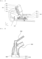
- FIG. 4 is a schematic view of a blasting gun of the combination of a welding jig and a welding jig micro-cleaning apparatus according to an embodiment of the present invention.
- the welding jig micro-cleaning apparatus includes a housing 100, a sandbox 200, an air supply unit 300, a controller 400, a jig fixing portion 600, and a blasting gun 500.
- the jig fixing portion and the blasting gun are positioned in the housing 100.
- the housing is a portion that defines the external appearance of the welding jig micro-cleaning apparatus.
- the housing 100 may be formed in a hexahedral shape having an empty inner space.
- a housing door 110 may be positioned at an upper part of a front end of the housing 100.
- the housing door 110 may be configured to open and close a part of a front surface of the housing 100 and a part of an upper end of the housing.
- a welding jig 700 a description of which will follow, may be mounted to the jig fixing portion 600 located in the housing or may be separated from the jig fixing portion 600 and taken out to the outside.
- the housing door 110 may be manually opened and closed, and may be connected to an automatic control system so as to be automatically opened and closed as needed.
- a sealing means may be provided at a portion at which an edge of the housing door 110 and the housing 100 are connected to each other in tight contact with each other in order to hermetically seal the interior of the housing, whereby it is possible to prevent polluted sand or other pollutants dispersed during cleaning from being discharged to the outside.
- An observation window 120 may be provided in a front surface (xz plane) of the housing door 110. Cleaning of the welding jig 700 in the housing 100 may be observed through the observation window 120.
- the sandbox 200 may be located above the housing 100, and the air supply unit 300 may be connected to the sandbox 200.
- the sandbox 200 may be formed in an approximately cylindrical shape or an approximately hexahedral shape. However, the shape of the sandbox is not particularly restricted as long as sand and other necessary members can be received in an inner space thereof.
- the air supply unit 300 may be an air compressor. Compressed air from the air supply unit 300 may be supplied to the sandbox 200 through a compressed air supply hose (not shown). A compressed air distribution means (not shown), a cut-off valve (not shown), a pressure control valve (not shown), and a flow control valve (not shown) may be disposed in the compressed air supply hose. Compressed air from the air supply unit 300 may be supplied to the sandbox 200 and other rear equipment through the compressed air distribution means.
- First compressed air (not shown), which is some of compressed air from the air supply unit 300, may be supplied to the sandbox 200 through a connection pipe (not shown) so as to be mixed with sand.
- a sand and air discharge port may be located at a lower end of the sandbox 200, and a three-way valve (not shown) may be located in the air discharge port.
- Sand and air mixed in the sandbox 200 may be introduced into a first hole of the three-way valve, and second compressed air (not shown), which is compressed air from the air supply unit 300, may be introduced into a second hole of the three-way valve.
- the compressed air introduced into the second hole and the sand and air mixture introduced into the first hole may be discharged together through a third hole of the three-way valve.
- the third hole may be connected to a supply hose 530 in order to transfer the sand supplied from the sandbox 200 to the blasting gun 500.
- the amount and flow speed of sand supplied to the supply hose 530 may be adjusted using the first compressed air and the second compressed air, and a control valve (not shown) may be mounted on a transfer line for the first compressed air and the second compressed air in order to adjust the flow rate of compressed air.
- controller 400 will be described.
- the controller 400 may be connected to a side surface of the housing 100.
- the controller 400 may control driving of the air supply unit 300, operation of the control valve (not shown) configured to adjust flow rate of compressed air, upward and downward movement of a support portion 550 of the blasting gun 500, a description of which will follow, on and off of a magnetic unit, and horizontal movement and rotation of a sliding unit 620, a description of which will follow.
- a supply hose 530 connected to the third hole of the three-way valve located at the lower end of the sandbox 200 is connected to the blasting gun 500 to supply the sand and the compressed air discharged from the third hole of the three-way valve to the blasting gun 500.
- a discharge hose 520 is located spaced apart from the supply hose 530 by a predetermined distance, and the supply hose 530 and the discharge hose 520 extend into a body portion 540 so as to be connected to the body portion 540. Flow of a fluid in the supply hose 530, the discharge hose 520, and the body portion 540 will be described below in detail.
- the blasting gun inlet 510 may include a discharge port 511 and a suction port 512.
- the discharge port 511 may be located at a tip end of an internal flow path (not shown) of the body portion 540 to which the supply hose 530 extending into the body portion 540 is connected.
- the discharge port 511 may spray the sand and the compressed air supplied from the supply hose 530 to the welding jig 700, a description of which will follow, disposed thereunder in order to clean the welding jig.
- the internal flow path of the body portion 540 may be a hose or a stainless steel pipe.
- a partition wall of the body portion 540 is spaced apart from a partition wall of the internal flow path while wrapping the internal flow path of the body portion 540, whereby a space functioning as an external flow path (not shown) is formed.
- the partition wall of the body portion 540 and the partition wall of the internal flow path are spaced apart from each other, whereby the suction port 512 is formed at a tip end of the blasting gun inlet 510.
- the suction port 512 is located around the discharge port 511.
- the discharge hose 520 is connected to the body portion 540 through the partition wall of the body portion so as to be opposite the suction port 512 in the state in which the external flow path is located therebetween.
- the sprayed sand and the pollutants separated from the welding jig 700 are suctioned through the suction port 512.
- the tip end surface of the sealing portion 560 which is brought into tight contact with the die 610, a description of which will follow, may be coated with a metal material.
- the extent of tight contact between the sealing portion and the die 610 is improved by a magnetic unit 640, a description of which will follow, which is advantageous in suctioning the removed pollutant, such as spatter.
- the jig fixing portion 600 may be located under the blasting gun 500, and may include a die 610, a sliding unit 620, a sliding slit 630, and a magnetic unit 640.
- the welding jig 700 is located at an upper end of the die 610 so as to be cleaned by the sand and the compressed air sprayed from the discharge port 511 of the blasting gun 500.
- the die 610 may have a plate shape.
- the magnetic unit 640 may be located at the die 610 in order to fix the welding jig 700, whereby it is possible to prevent separation or displacement of the welding jig 700 during a cleaning process.
- the magnetic unit 640 may be constituted by a permanent magnet or an electromagnet.
- the magnetic unit is constituted by an electromagnet
- an on-off lever (not shown) may be provided.
- the magnetic unit 640 may be magnetized or demagnetized by manipulation of the on-off lever.
- magnetic force of the magnetic unit may be controlled. In the present invention, therefore, it is preferable for the magnetic unit 640 to be constituted by an electromagnet.
- the die 610 may be connected to the sliding unit 620, and the sliding unit 620 may be connected to a rear sliding driving portion (not shown) through the sliding slit 630, which is formed in the partition wall of the housing 100.
- the sliding unit 620 may be moved leftwards and rightwards in a horizontal direction by manipulation of the sliding driving portion.
- the welding jig 700 After the welding jig 700 is mounted to the upper end of the die 610, the welding jig 700 may be moved under the blasting gun inlet 510 through operation of the sliding unit 620, and cleaning may be performed.
- a hinge coupling portion (not shown) provided at the sliding unit 620 to allow the die 610 to be rotated by a predetermined angle may be included.
- a disposition angle of the welding jig 700 may be adjusted, which is advantageous in effectively removing pollutants from a bent portion of the welding jig 700 through cleaning.
Landscapes
- Engineering & Computer Science (AREA)
- Mechanical Engineering (AREA)
- Physics & Mathematics (AREA)
- Optics & Photonics (AREA)
- Plasma & Fusion (AREA)
- Cleaning In General (AREA)
Claims (11)
- Kombination einer Schweißvorrichtung (700) und einer Mikroreinigungsvorrichtung für eine Schweiß-Spannvorrichtung, aufweisend:ein Gehäuse (100);eine Sandbox (200), die mit dem Gehäuse (100) verbunden ist;eine Luftversorgungseinheit (300), die über einen Schlauch mit der Sandbox (200) verbunden ist;eine Strahlkanone (500), die in dem Gehäuse (100) positioniert ist, wobei die Strahlkanone (500) einen Strahlkanoneneinlass (510) aufweist, der an einem Spitzenende der Strahlkanone (500) vorgesehen ist, und
wobei der Strahlkanoneneinlass (510) eine Auslassöffnung (511) und eine Ansaugöffnung (512) aufweist;einen Spannvorrichtungs-Befestigungsabschnitt (600), der an einem unteren Ende der Strahlkanone (500) positioniert ist, wobei die Schweiß-Spannvorrichtung (700) an dem Spannvorrichtungs-Befestigungsabschnitt (600) montiert ist, der sich in dem Gehäuse (100) befindet; undeine Steuerung (400),wobei der Spannvorrichtungs-Befestigungsabschnitt (600) eine Magneteinheit (640), die konfiguriert ist, um die Schweiß-Spannvorrichtung (700) zu befestigen, und eine Schiebeeinheit (620) aufweist, die horizontal an dem unteren Ende der Strahlkanone (500) bewegbar ist, so dass die Schweiß-Spannvorrichtung (700) unter dem Strahlkanoneneinlass (510) durch Betätigung der Schiebeeinheit (620) bewegbar ist. - Kombination nach Anspruch 1, wobei die Schiebeeinheit (620) um einen vorbestimmten Winkel in einer horizontalen Richtung drehbar ist.
- Kombination nach einem der vorhergehenden Ansprüche, wobei der Strahlkanoneneinlass (510) einen Dichtungsabschnitt (560) aufweist.
- Kombination nach Anspruch 3, wobei der Dichtungsabschnitt (560) einen Die (610) des Spannvorrichtungs-Befestigungsabschnitts (600) berührt, so dass die Schweiß-Spannvorrichtung (700) in einem Innenraum des Dichtungsabschnitts (560) positioniert ist.
- Kombination nach Anspruch 4, wobei, wenn die Schweiß-Spannvorrichtung (700) unter dem Strahlkanoneneinlass (510) der Strahlkanone (500) durch Betätigung der Schiebeeinheit (620) bewegt wird, eine Reinigung durchgeführt werden kann.
- Kombination nach Anspruch 3, wobei der Dichtungsabschnitt (560) aus einem elastischen Material hergestellt ist.
- Kombination nach Anspruch 6, wobei eine Spitzenendfläche des Dichtungsabschnitts (560), die in engen Kontakt mit einem Die (610) des Spannvorrichtungs-Befestigungsabschnitts (600) gebracht wird, mit einem Metallmaterial beschichtet ist.
- Kombination nach Anspruch 1, wobei die Strahlkanone (500) mit einer Bewegungseinheit so verbunden ist, dass sie nach oben und unten beweglich ist.
- Kombination nach Anspruch 1, wobei die Sandbox (200) und die Luftversorgungseinheit (300) so konfiguriert sind, dass sie die Zufuhrmengen an Luft und Sand unter der Steuerung der Steuerung (400) einstellen.
- Kombination nach Anspruch 9, wobei sich ein Dreiwegeventil in einer Luftauslassöffnung befindet, wobei Sand und Luft, die in der Sandbox (200) gemischt sind, in ein erstes Loch des Dreiwegeventils eingeführt werden, und zweite Druckluft von der Luftversorgungseinheit (300) in ein zweites Loch des Dreiwegeventils eingeführt wird, und wobei die zweite Druckluft, die in das zweite Loch eingeführt wird, und das Sand-Luft-Gemisch, das in das erste Loch eingeführt wird, zusammen durch ein drittes Loch des Dreiwegeventils, das mit einem Versorgungsschlauch (530) verbunden ist, ausgelassen werden, um den Sand, der von der Sandbox (200) zugeführt wird, zu der Strahlkanone (500) zu übertragen.
- Kombination nach Anspruch 1, wobei das Gehäuse (100) eine Gehäusetür (110) aufweist, und
wobei die Gehäusetür (100) ein Beobachtungsfenster (120) aufweist.
Applications Claiming Priority (2)
| Application Number | Priority Date | Filing Date | Title |
|---|---|---|---|
| KR1020210004088A KR102830240B1 (ko) | 2021-01-12 | 2021-01-12 | 용접 지그 마이크로 클리닝 장치 |
| PCT/KR2022/000081 WO2022154351A1 (ko) | 2021-01-12 | 2022-01-04 | 용접 지그 마이크로 클리닝 장치 |
Publications (3)
| Publication Number | Publication Date |
|---|---|
| EP4108371A1 EP4108371A1 (de) | 2022-12-28 |
| EP4108371A4 EP4108371A4 (de) | 2023-08-23 |
| EP4108371B1 true EP4108371B1 (de) | 2024-09-18 |
Family
ID=82448328
Family Applications (1)
| Application Number | Title | Priority Date | Filing Date |
|---|---|---|---|
| EP22739549.8A Active EP4108371B1 (de) | 2021-01-12 | 2022-01-04 | Mikroreinigungsvorrichtung für eine schweissvorrichtung |
Country Status (7)
| Country | Link |
|---|---|
| US (1) | US20230142000A1 (de) |
| EP (1) | EP4108371B1 (de) |
| KR (1) | KR102830240B1 (de) |
| CN (1) | CN115427180A (de) |
| ES (1) | ES3001437T3 (de) |
| HU (1) | HUE069078T2 (de) |
| WO (1) | WO2022154351A1 (de) |
Families Citing this family (2)
| Publication number | Priority date | Publication date | Assignee | Title |
|---|---|---|---|---|
| KR102535802B1 (ko) * | 2022-11-16 | 2023-05-26 | 링크온코리아 주식회사 | 레이저를 이용한 슬롯홈의 스패터 제거 장치 |
| KR20250147052A (ko) * | 2024-04-03 | 2025-10-13 | 삼성에스디아이 주식회사 | 이차 전지용 이물 검사장치를 위한 마스터 지그장치 |
Family Cites Families (21)
| Publication number | Priority date | Publication date | Assignee | Title |
|---|---|---|---|---|
| DE4123020C2 (de) * | 1991-07-11 | 2002-03-21 | Kaltenbach & Voigt | Bearbeitungsgerät zum Bearbeiten von feinwerktechnischen, insbesondere dentaltechnischen Werkstücken in einem von einem Gehäuse umgebenen Bearbeitungsraum |
| JPH08132346A (ja) * | 1994-11-04 | 1996-05-28 | Alps Eng:Kk | ワーク固定装置 |
| KR19990033416A (ko) * | 1997-10-24 | 1999-05-15 | 정몽규 | 이동식 블라스터 |
| KR100352293B1 (ko) * | 2000-08-01 | 2002-09-12 | (주)나이테산기개발 | 샌드블라스트기 |
| KR20040071358A (ko) * | 2003-02-05 | 2004-08-12 | 삼성전자주식회사 | 샌드 블래스터 |
| WO2011014913A1 (en) * | 2009-08-04 | 2011-02-10 | Andrew Hill | Portable containment device |
| GB0921374D0 (en) * | 2009-12-04 | 2010-01-20 | Pinovo As | Apparatus |
| CN102267101B (zh) * | 2010-06-04 | 2014-12-03 | 新东工业株式会社 | 板状部件的加工装置及其加工方法 |
| TW201200297A (en) * | 2010-06-22 | 2012-01-01 | Hon Hai Prec Ind Co Ltd | Sand-blasting apparatus and method for shaping product with same |
| CN204366752U (zh) * | 2014-12-16 | 2015-06-03 | 天津中鼎铝业有限公司 | 一种吸入式干喷砂机 |
| CN106078532A (zh) * | 2016-08-23 | 2016-11-09 | 郭继安 | 喷砂机 |
| KR101874041B1 (ko) * | 2016-11-14 | 2018-07-05 | 삼성중공업 주식회사 | 블라스팅 장치 |
| KR101988335B1 (ko) | 2017-08-11 | 2019-06-12 | (주)호원 | 용접 노즐 클리닝장치 |
| KR102068346B1 (ko) * | 2018-01-15 | 2020-01-20 | 김득배 | 반자동 블라스팅 장치 |
| CN109015416A (zh) * | 2018-10-24 | 2018-12-18 | 鹰普航空零部件(无锡)有限公司 | 悬浮式喷砂机 |
| CN109262473A (zh) * | 2018-11-22 | 2019-01-25 | 天津商业大学 | 一种用于曲面壳体类零件的精密数控喷砂机 |
| CN110125812B (zh) * | 2019-05-24 | 2021-04-30 | 广州威品技术研发有限公司 | 一种金属面板喷砂及夹持机构 |
| KR20210004088A (ko) | 2019-07-03 | 2021-01-13 | 전선영 | 깔라만시 순수원료로 다이어트 및 변비개선에 효과가있는 가공물 제조방법 |
| CN111002231B (zh) * | 2019-12-19 | 2021-08-20 | 苏州知云创宇信息科技有限公司 | 一种磨料喷射装置 |
| CN211439591U (zh) * | 2019-12-30 | 2020-09-08 | 昆山炫鹏机械设备制造有限公司 | 一种精密零件表面喷砂装置 |
| CN111590470B (zh) * | 2020-04-29 | 2021-11-16 | 江苏八达重工科技有限公司 | 一种金属板件表面除锈喷砂装置 |
-
2021
- 2021-01-12 KR KR1020210004088A patent/KR102830240B1/ko active Active
-
2022
- 2022-01-04 US US17/915,347 patent/US20230142000A1/en active Pending
- 2022-01-04 ES ES22739549T patent/ES3001437T3/es active Active
- 2022-01-04 EP EP22739549.8A patent/EP4108371B1/de active Active
- 2022-01-04 HU HUE22739549A patent/HUE069078T2/hu unknown
- 2022-01-04 CN CN202280003449.6A patent/CN115427180A/zh active Pending
- 2022-01-04 WO PCT/KR2022/000081 patent/WO2022154351A1/ko not_active Ceased
Also Published As
| Publication number | Publication date |
|---|---|
| KR20220101963A (ko) | 2022-07-19 |
| KR102830240B1 (ko) | 2025-07-07 |
| EP4108371A4 (de) | 2023-08-23 |
| HUE069078T2 (hu) | 2025-02-28 |
| WO2022154351A1 (ko) | 2022-07-21 |
| CN115427180A (zh) | 2022-12-02 |
| US20230142000A1 (en) | 2023-05-11 |
| EP4108371A1 (de) | 2022-12-28 |
| ES3001437T3 (en) | 2025-03-05 |
Similar Documents
| Publication | Publication Date | Title |
|---|---|---|
| KR102414044B1 (ko) | 전지 셀에 부착 가능한 접착 테이프용 테이핑 장치 및 테이핑 방법 | |
| EP4108371A1 (de) | Mikroreinigungsvorrichtung für eine schweissvorrichtung | |
| CN115475986B (zh) | 清洁设备、电池单体、用电装置及电池单体加工方法 | |
| KR102166039B1 (ko) | 배터리 원료 투입장치 | |
| CN203398203U (zh) | 正负极耳焊接机 | |
| CN102267101B (zh) | 板状部件的加工装置及其加工方法 | |
| KR20100019341A (ko) | 연마재 회수 시스템을 갖는 블라스트 가공 방법 및 장치, 박막 태양전지 패널의 가공 방법 및 이에 의해 가공된 박막 태양전지 패널 | |
| US20220209340A1 (en) | End cover assembly, battery cell and electrolyte injection method therefor, battery, and power consumption device | |
| CN117583725A (zh) | 焊接除尘装置 | |
| CN222077056U (zh) | 涂布模头及涂布装置 | |
| CN115832388A (zh) | 贴膜装置、贴膜系统和贴膜方法 | |
| CN220329480U (zh) | 一种易于密封的除尘设备 | |
| CN118385801A (zh) | 一种锂电池焊接设备 | |
| CN116706472A (zh) | 顶盖清洗方法、装置、电池单体、电池以及用电装置 | |
| KR102962589B1 (ko) | 용접 지그 클리닝 장치 | |
| CN223454435U (zh) | 一种喷涂工艺防护工装 | |
| CN112295777B (zh) | 喷涂辅助装置 | |
| CN221294383U (zh) | 撕膜装置及撕膜设备 | |
| CN113967782A (zh) | 超声波除尘装置 | |
| JPH08131973A (ja) | マグネット密着、剥離交互動作式の移動密閉構造 | |
| CN224072883U (zh) | 除尘组件、除尘装置和电池生产线 | |
| CN221230962U (zh) | 涂胶装置以及电池生产系统 | |
| CN115365687B (zh) | 焊接切割系统 | |
| CN118207612B (zh) | 一种适用于手机保护膜的单面电镀设备 | |
| CN119076264A (zh) | 一种喷涂工艺防护工装及工艺 |
Legal Events
| Date | Code | Title | Description |
|---|---|---|---|
| STAA | Information on the status of an ep patent application or granted ep patent |
Free format text: STATUS: THE INTERNATIONAL PUBLICATION HAS BEEN MADE |
|
| PUAI | Public reference made under article 153(3) epc to a published international application that has entered the european phase |
Free format text: ORIGINAL CODE: 0009012 |
|
| STAA | Information on the status of an ep patent application or granted ep patent |
Free format text: STATUS: REQUEST FOR EXAMINATION WAS MADE |
|
| 17P | Request for examination filed |
Effective date: 20220920 |
|
| AK | Designated contracting states |
Kind code of ref document: A1 Designated state(s): AL AT BE BG CH CY CZ DE DK EE ES FI FR GB GR HR HU IE IS IT LI LT LU LV MC MK MT NL NO PL PT RO RS SE SI SK SM TR |
|
| A4 | Supplementary search report drawn up and despatched |
Effective date: 20230725 |
|
| RIC1 | Information provided on ipc code assigned before grant |
Ipc: B24C 7/00 20060101ALI20230719BHEP Ipc: B24C 5/02 20060101ALI20230719BHEP Ipc: B24C 9/00 20060101ALI20230719BHEP Ipc: B24C 1/08 20060101ALI20230719BHEP Ipc: B23K 37/04 20060101ALI20230719BHEP Ipc: B23K 9/32 20060101AFI20230719BHEP |
|
| STAA | Information on the status of an ep patent application or granted ep patent |
Free format text: STATUS: EXAMINATION IS IN PROGRESS |
|
| 17Q | First examination report despatched |
Effective date: 20240124 |
|
| DAV | Request for validation of the european patent (deleted) | ||
| DAX | Request for extension of the european patent (deleted) | ||
| GRAP | Despatch of communication of intention to grant a patent |
Free format text: ORIGINAL CODE: EPIDOSNIGR1 |
|
| STAA | Information on the status of an ep patent application or granted ep patent |
Free format text: STATUS: GRANT OF PATENT IS INTENDED |
|
| INTG | Intention to grant announced |
Effective date: 20240617 |
|
| GRAS | Grant fee paid |
Free format text: ORIGINAL CODE: EPIDOSNIGR3 |
|
| GRAA | (expected) grant |
Free format text: ORIGINAL CODE: 0009210 |
|
| STAA | Information on the status of an ep patent application or granted ep patent |
Free format text: STATUS: THE PATENT HAS BEEN GRANTED |
|
| AK | Designated contracting states |
Kind code of ref document: B1 Designated state(s): AL AT BE BG CH CY CZ DE DK EE ES FI FR GB GR HR HU IE IS IT LI LT LU LV MC MK MT NL NO PL PT RO RS SE SI SK SM TR |
|
| P01 | Opt-out of the competence of the unified patent court (upc) registered |
Free format text: CASE NUMBER: APP_46757/2024 Effective date: 20240813 |
|
| REG | Reference to a national code |
Ref country code: GB Ref legal event code: FG4D |
|
| REG | Reference to a national code |
Ref country code: CH Ref legal event code: EP |
|
| REG | Reference to a national code |
Ref country code: IE Ref legal event code: FG4D |
|
| REG | Reference to a national code |
Ref country code: DE Ref legal event code: R096 Ref document number: 602022006241 Country of ref document: DE |
|
| REG | Reference to a national code |
Ref country code: LT Ref legal event code: MG9D |
|
| PG25 | Lapsed in a contracting state [announced via postgrant information from national office to epo] |
Ref country code: NO Free format text: LAPSE BECAUSE OF FAILURE TO SUBMIT A TRANSLATION OF THE DESCRIPTION OR TO PAY THE FEE WITHIN THE PRESCRIBED TIME-LIMIT Effective date: 20241218 |
|
| PG25 | Lapsed in a contracting state [announced via postgrant information from national office to epo] |
Ref country code: GR Free format text: LAPSE BECAUSE OF FAILURE TO SUBMIT A TRANSLATION OF THE DESCRIPTION OR TO PAY THE FEE WITHIN THE PRESCRIBED TIME-LIMIT Effective date: 20241219 Ref country code: FI Free format text: LAPSE BECAUSE OF FAILURE TO SUBMIT A TRANSLATION OF THE DESCRIPTION OR TO PAY THE FEE WITHIN THE PRESCRIBED TIME-LIMIT Effective date: 20240918 |
|
| PG25 | Lapsed in a contracting state [announced via postgrant information from national office to epo] |
Ref country code: BG Free format text: LAPSE BECAUSE OF FAILURE TO SUBMIT A TRANSLATION OF THE DESCRIPTION OR TO PAY THE FEE WITHIN THE PRESCRIBED TIME-LIMIT Effective date: 20240918 |
|
| PG25 | Lapsed in a contracting state [announced via postgrant information from national office to epo] |
Ref country code: LV Free format text: LAPSE BECAUSE OF FAILURE TO SUBMIT A TRANSLATION OF THE DESCRIPTION OR TO PAY THE FEE WITHIN THE PRESCRIBED TIME-LIMIT Effective date: 20240918 |
|
| PG25 | Lapsed in a contracting state [announced via postgrant information from national office to epo] |
Ref country code: HR Free format text: LAPSE BECAUSE OF FAILURE TO SUBMIT A TRANSLATION OF THE DESCRIPTION OR TO PAY THE FEE WITHIN THE PRESCRIBED TIME-LIMIT Effective date: 20240918 |
|
| REG | Reference to a national code |
Ref country code: NL Ref legal event code: MP Effective date: 20240918 |
|
| PG25 | Lapsed in a contracting state [announced via postgrant information from national office to epo] |
Ref country code: RS Free format text: LAPSE BECAUSE OF FAILURE TO SUBMIT A TRANSLATION OF THE DESCRIPTION OR TO PAY THE FEE WITHIN THE PRESCRIBED TIME-LIMIT Effective date: 20241218 |
|
| PG25 | Lapsed in a contracting state [announced via postgrant information from national office to epo] |
Ref country code: RS Free format text: LAPSE BECAUSE OF FAILURE TO SUBMIT A TRANSLATION OF THE DESCRIPTION OR TO PAY THE FEE WITHIN THE PRESCRIBED TIME-LIMIT Effective date: 20241218 Ref country code: NO Free format text: LAPSE BECAUSE OF FAILURE TO SUBMIT A TRANSLATION OF THE DESCRIPTION OR TO PAY THE FEE WITHIN THE PRESCRIBED TIME-LIMIT Effective date: 20241218 Ref country code: LV Free format text: LAPSE BECAUSE OF FAILURE TO SUBMIT A TRANSLATION OF THE DESCRIPTION OR TO PAY THE FEE WITHIN THE PRESCRIBED TIME-LIMIT Effective date: 20240918 Ref country code: HR Free format text: LAPSE BECAUSE OF FAILURE TO SUBMIT A TRANSLATION OF THE DESCRIPTION OR TO PAY THE FEE WITHIN THE PRESCRIBED TIME-LIMIT Effective date: 20240918 Ref country code: GR Free format text: LAPSE BECAUSE OF FAILURE TO SUBMIT A TRANSLATION OF THE DESCRIPTION OR TO PAY THE FEE WITHIN THE PRESCRIBED TIME-LIMIT Effective date: 20241219 Ref country code: FI Free format text: LAPSE BECAUSE OF FAILURE TO SUBMIT A TRANSLATION OF THE DESCRIPTION OR TO PAY THE FEE WITHIN THE PRESCRIBED TIME-LIMIT Effective date: 20240918 Ref country code: BG Free format text: LAPSE BECAUSE OF FAILURE TO SUBMIT A TRANSLATION OF THE DESCRIPTION OR TO PAY THE FEE WITHIN THE PRESCRIBED TIME-LIMIT Effective date: 20240918 |
|
| REG | Reference to a national code |
Ref country code: AT Ref legal event code: MK05 Ref document number: 1724270 Country of ref document: AT Kind code of ref document: T Effective date: 20240918 |
|
| PG25 | Lapsed in a contracting state [announced via postgrant information from national office to epo] |
Ref country code: NL Free format text: LAPSE BECAUSE OF FAILURE TO SUBMIT A TRANSLATION OF THE DESCRIPTION OR TO PAY THE FEE WITHIN THE PRESCRIBED TIME-LIMIT Effective date: 20240918 |
|
| REG | Reference to a national code |
Ref country code: HU Ref legal event code: AG4A Ref document number: E069078 Country of ref document: HU |
|
| PG25 | Lapsed in a contracting state [announced via postgrant information from national office to epo] |
Ref country code: PT Free format text: LAPSE BECAUSE OF FAILURE TO SUBMIT A TRANSLATION OF THE DESCRIPTION OR TO PAY THE FEE WITHIN THE PRESCRIBED TIME-LIMIT Effective date: 20250120 Ref country code: IS Free format text: LAPSE BECAUSE OF FAILURE TO SUBMIT A TRANSLATION OF THE DESCRIPTION OR TO PAY THE FEE WITHIN THE PRESCRIBED TIME-LIMIT Effective date: 20250118 |
|
| PG25 | Lapsed in a contracting state [announced via postgrant information from national office to epo] |
Ref country code: RO Free format text: LAPSE BECAUSE OF FAILURE TO SUBMIT A TRANSLATION OF THE DESCRIPTION OR TO PAY THE FEE WITHIN THE PRESCRIBED TIME-LIMIT Effective date: 20240918 Ref country code: SM Free format text: LAPSE BECAUSE OF FAILURE TO SUBMIT A TRANSLATION OF THE DESCRIPTION OR TO PAY THE FEE WITHIN THE PRESCRIBED TIME-LIMIT Effective date: 20240918 |
|
| PG25 | Lapsed in a contracting state [announced via postgrant information from national office to epo] |
Ref country code: AT Free format text: LAPSE BECAUSE OF FAILURE TO SUBMIT A TRANSLATION OF THE DESCRIPTION OR TO PAY THE FEE WITHIN THE PRESCRIBED TIME-LIMIT Effective date: 20240918 Ref country code: EE Free format text: LAPSE BECAUSE OF FAILURE TO SUBMIT A TRANSLATION OF THE DESCRIPTION OR TO PAY THE FEE WITHIN THE PRESCRIBED TIME-LIMIT Effective date: 20240918 |
|
| PG25 | Lapsed in a contracting state [announced via postgrant information from national office to epo] |
Ref country code: PL Free format text: LAPSE BECAUSE OF FAILURE TO SUBMIT A TRANSLATION OF THE DESCRIPTION OR TO PAY THE FEE WITHIN THE PRESCRIBED TIME-LIMIT Effective date: 20240918 Ref country code: CZ Free format text: LAPSE BECAUSE OF FAILURE TO SUBMIT A TRANSLATION OF THE DESCRIPTION OR TO PAY THE FEE WITHIN THE PRESCRIBED TIME-LIMIT Effective date: 20240918 |
|
| PG25 | Lapsed in a contracting state [announced via postgrant information from national office to epo] |
Ref country code: SK Free format text: LAPSE BECAUSE OF FAILURE TO SUBMIT A TRANSLATION OF THE DESCRIPTION OR TO PAY THE FEE WITHIN THE PRESCRIBED TIME-LIMIT Effective date: 20240918 Ref country code: IT Free format text: LAPSE BECAUSE OF FAILURE TO SUBMIT A TRANSLATION OF THE DESCRIPTION OR TO PAY THE FEE WITHIN THE PRESCRIBED TIME-LIMIT Effective date: 20240918 |
|
| REG | Reference to a national code |
Ref country code: DE Ref legal event code: R097 Ref document number: 602022006241 Country of ref document: DE |
|
| PG25 | Lapsed in a contracting state [announced via postgrant information from national office to epo] |
Ref country code: DK Free format text: LAPSE BECAUSE OF FAILURE TO SUBMIT A TRANSLATION OF THE DESCRIPTION OR TO PAY THE FEE WITHIN THE PRESCRIBED TIME-LIMIT Effective date: 20240918 |
|
| PLBE | No opposition filed within time limit |
Free format text: ORIGINAL CODE: 0009261 |
|
| STAA | Information on the status of an ep patent application or granted ep patent |
Free format text: STATUS: NO OPPOSITION FILED WITHIN TIME LIMIT |
|
| 26N | No opposition filed |
Effective date: 20250619 |
|
| REG | Reference to a national code |
Ref country code: CH Ref legal event code: PL |
|
| PG25 | Lapsed in a contracting state [announced via postgrant information from national office to epo] |
Ref country code: SE Free format text: LAPSE BECAUSE OF FAILURE TO SUBMIT A TRANSLATION OF THE DESCRIPTION OR TO PAY THE FEE WITHIN THE PRESCRIBED TIME-LIMIT Effective date: 20240918 |
|
| PG25 | Lapsed in a contracting state [announced via postgrant information from national office to epo] |
Ref country code: MC Free format text: LAPSE BECAUSE OF FAILURE TO SUBMIT A TRANSLATION OF THE DESCRIPTION OR TO PAY THE FEE WITHIN THE PRESCRIBED TIME-LIMIT Effective date: 20240918 Ref country code: LU Free format text: LAPSE BECAUSE OF NON-PAYMENT OF DUE FEES Effective date: 20250104 |
|
| PG25 | Lapsed in a contracting state [announced via postgrant information from national office to epo] |
Ref country code: CH Free format text: LAPSE BECAUSE OF NON-PAYMENT OF DUE FEES Effective date: 20250131 |
|
| PGFP | Annual fee paid to national office [announced via postgrant information from national office to epo] |
Ref country code: GB Payment date: 20251222 Year of fee payment: 5 |
|
| PGFP | Annual fee paid to national office [announced via postgrant information from national office to epo] |
Ref country code: FR Payment date: 20251223 Year of fee payment: 5 |
|
| PGFP | Annual fee paid to national office [announced via postgrant information from national office to epo] |
Ref country code: BE Payment date: 20251229 Year of fee payment: 5 |
|
| PG25 | Lapsed in a contracting state [announced via postgrant information from national office to epo] |
Ref country code: IE Free format text: LAPSE BECAUSE OF NON-PAYMENT OF DUE FEES Effective date: 20250104 |
|
| PGFP | Annual fee paid to national office [announced via postgrant information from national office to epo] |
Ref country code: HU Payment date: 20260129 Year of fee payment: 5 |
|
| PGFP | Annual fee paid to national office [announced via postgrant information from national office to epo] |
Ref country code: ES Payment date: 20260212 Year of fee payment: 5 |
|
| PGFP | Annual fee paid to national office [announced via postgrant information from national office to epo] |
Ref country code: DE Payment date: 20251222 Year of fee payment: 5 |