EP4107472B1 - Kanisteranordnung mit geschützter verschlusskappe und damit versehener booster-sprengstoff - Google Patents
Kanisteranordnung mit geschützter verschlusskappe und damit versehener booster-sprengstoff Download PDFInfo
- Publication number
- EP4107472B1 EP4107472B1 EP21756259.4A EP21756259A EP4107472B1 EP 4107472 B1 EP4107472 B1 EP 4107472B1 EP 21756259 A EP21756259 A EP 21756259A EP 4107472 B1 EP4107472 B1 EP 4107472B1
- Authority
- EP
- European Patent Office
- Prior art keywords
- protective sleeve
- cap well
- canister
- canister assembly
- detonator
- Prior art date
- Legal status (The legal status is an assumption and is not a legal conclusion. Google has not performed a legal analysis and makes no representation as to the accuracy of the status listed.)
- Active
Links
Images


Classifications
-
- F—MECHANICAL ENGINEERING; LIGHTING; HEATING; WEAPONS; BLASTING
- F42—AMMUNITION; BLASTING
- F42B—EXPLOSIVE CHARGES, e.g. FOR BLASTING, FIREWORKS, AMMUNITION
- F42B3/00—Blasting cartridges, i.e. case and explosive
- F42B3/10—Initiators therefor
-
- C—CHEMISTRY; METALLURGY
- C06—EXPLOSIVES; MATCHES
- C06C—DETONATING OR PRIMING DEVICES; FUSES; CHEMICAL LIGHTERS; PYROPHORIC COMPOSITIONS
- C06C5/00—Fuses, e.g. fuse cords
- C06C5/04—Detonating fuses
-
- F—MECHANICAL ENGINEERING; LIGHTING; HEATING; WEAPONS; BLASTING
- F42—AMMUNITION; BLASTING
- F42B—EXPLOSIVE CHARGES, e.g. FOR BLASTING, FIREWORKS, AMMUNITION
- F42B3/00—Blasting cartridges, i.e. case and explosive
- F42B3/08—Blasting cartridges, i.e. case and explosive with cavities in the charge, e.g. hollow-charge blasting cartridges
-
- F—MECHANICAL ENGINEERING; LIGHTING; HEATING; WEAPONS; BLASTING
- F42—AMMUNITION; BLASTING
- F42B—EXPLOSIVE CHARGES, e.g. FOR BLASTING, FIREWORKS, AMMUNITION
- F42B3/00—Blasting cartridges, i.e. case and explosive
- F42B3/24—Cartridge closures or seals
-
- F—MECHANICAL ENGINEERING; LIGHTING; HEATING; WEAPONS; BLASTING
- F42—AMMUNITION; BLASTING
- F42B—EXPLOSIVE CHARGES, e.g. FOR BLASTING, FIREWORKS, AMMUNITION
- F42B3/00—Blasting cartridges, i.e. case and explosive
- F42B3/26—Arrangements for mounting initiators; Accessories therefor, e.g. tools
-
- F—MECHANICAL ENGINEERING; LIGHTING; HEATING; WEAPONS; BLASTING
- F42—AMMUNITION; BLASTING
- F42B—EXPLOSIVE CHARGES, e.g. FOR BLASTING, FIREWORKS, AMMUNITION
- F42B3/00—Blasting cartridges, i.e. case and explosive
- F42B3/28—Cartridge cases characterised by the material used, e.g. coatings
-
- F—MECHANICAL ENGINEERING; LIGHTING; HEATING; WEAPONS; BLASTING
- F42—AMMUNITION; BLASTING
- F42B—EXPLOSIVE CHARGES, e.g. FOR BLASTING, FIREWORKS, AMMUNITION
- F42B33/00—Manufacture of ammunition; Dismantling of ammunition; Apparatus therefor
- F42B33/02—Filling cartridges, missiles, or fuzes; Inserting propellant or explosive charges
- F42B33/0214—Filling cartridges, missiles, or fuzes; Inserting propellant or explosive charges by casting
Definitions
- the present invention concerns novel canister assemblies for cast booster explosives, and cast booster explosives comprising the canister assemblies.
- Cast booster explosives are typically utilized to detonate normally cap-insensitive explosives such as ammonium nitrate and fuel oil (“ANFO”) bulk explosives.
- ANFO ammonium nitrate and fuel oil
- Cast booster explosives are normally cast with a fuse tunnel and a cap well, the tunnel providing a passageway for a fuse connected to a detonator (“cap”), which is received within the cap well.
- cap detonator
- U.S. Patent 9,115,963 assigned to the assignee of the present application, discloses a plastic canister having a fuse tunnel (22) formed integrally with the canister body (12) and a separate cap well (14) which may be secured within the canister body by means of a cap well mounting fixture (28).
- U.S. Patent 6,311,621 discloses an electronic circuit assembly in an encapsulation which may be enclosed within, e.g., a metal sleeve.
- U.S. Patent 4,334,476 issued June 15, 1982 to John T.
- U.S. Patent 4,425,849 issued on January 17, 1984 to Gordon K. Jorgenson for "Primer Assembly” discloses an explosive primer assembly which utilizes ( Figure 2 ) a primer explosive composition 6 which is initiated by a detonator 12 disposed within a cap well 8. Initiation is effectuated by a wire conductor 14 which passes through a toroid 10 which effectuates the initiation by electromagnetic induction.
- the embodiment illustrated in Figure 4 (column 3, line 61 et seq. ) encases detonator 12 within a tube 35 in order to provide a stable attachment of body 29 and its cover 30 to the cartridge of primer explosive shown in Figure 4 .
- Tube 35 has barbs 36 to help retain body 29 in place when tube element 35 is pressed into the cartridge.
- GB Patent Application 2 257 774 A to Hartley Hodgson published on January 20, 1993 discloses a shaped explosive charge 13 ( Fig. 2 ) having a metal barrier plate 1 having ( Fig.2 ) a cup-like deflector 4 and peripheral annular slots 6. Barrier plate 1 serves to deflect to the periphery of explosive charge 13 the explosive force of disc-like initiating charge 10 ( Fig. 2 ). Charge 10 is initiated by detonator 17/ explosive pellet 18.
- GB Patent 2 368 626 B to Wenbo Yang et al. published on September 8, 2004 is one of several Schlumberger patent publications showing provision of a shock-absorbing barrier to shield the explosives of well-perforating guns from the shock waves generated by adjacent explosives.
- Two basic shielding techniques are disclosed.
- One, as illustrated in Figure 3 is to enclose the perforating gun explosive charges 506 with a shock-impeding powder material 510 emplaced within sleeve 512.
- the shock-impeding material may be a porous cement comprising a mixture of cement and hollow microspheres (see the paragraph bridging pages 9 and 10 of this patent).
- Another shock-impeding technique is illustrated in Figure 7 of the patent where barriers 410 are interposed between shaped charges 412.
- US 2013/0206027 A1 discloses a rock cracker cartridge having an ignition assembly sleeve, a cracking powder charge and an ignition capsule with an ignition powder charge in an ignition unit sleeve, wherein the ignition assembly sleeve surrounds the ignition unit sleeve when the rock cracker cartridge is primed.
- RU 2 691 033 C1 discloses a canister assembly for a cast booster explosive, the canister assembly comprising a canister body defining a canister interior, and having a canister base, a cap well of generally tubular configuration disposed within the canister interior, the cap well having a length, an outside diameter and an active section, and a proximal open end, the cap well being configured to receive therewithin a detonator; and a protective sleeve surmounting the cap well, whereby the protective sleeve being configured to enclose a major portion of the length of the cap well.
- cast booster explosives are normally lowered into a borehole, which may be as deep as 10, 20 or 30 feet (3, 6.1 and 9.1 meters, respectively) or deeper. More than one booster may be loaded into a given borehole and in such case the two or more boosters are normally positioned at different depths within a given borehole.
- the booster explosive(s) are employed to initiate a bulk explosive such as an ANFO slurry or emulsion which is poured into the borehole.
- booster explosives are utilized in blasting systems which may comprise numerous boreholes filled with a suitable cap-insensitive explosive such as an ANFO slurry or emulsion. It is important that the sequence of explosions from borehole to borehole be carefully timed so that each borehole is detonated at an appropriate time in order to maximize blasting efficiency. If a "downstream" borehole is intended to be detonated after an adjacent or nearby "upstream” borehole, it is possible that the shock wave from the detonation of the upstream borehole may damage the detonator in the downstream borehole, so as to prevent the downstream borehole from initiating.
- the circuitry of electronic delay detonators is particularly vulnerable to damage by the shock waves generated by prior upstream or adjacent explosions. Failure of any borehole to detonate is of course highly undesirable. Detonation failures result in uninitiated explosives in muck piles, present severe safety hazards and greatly reduce the efficiency of the blasting system.
- the present invention is defined by claim 1 and provides a canister assembly and a booster explosive comprising the canister assembly.
- the canister assembly has a cap well which is protected by a shock-absorbing barrier to reduce the possibility of damage to the detonator lodged within the cap well by shock waves generated by prior adjacent explosions.
- the shock wave protection for the detonator is attained by enclosing a substantial portion of the cap well within a shock-absorbing barrier which may comprise a protective sleeve, while leaving unshielded an active section of the cap well, that is, the section of the cap well which encloses the explosive end section of the detonator.
- the protective sleeve may be made of any suitable material such as metal or plastic or a closed cell synthetic polymeric foam, or a combination thereof.
- a canister assembly for a cast booster explosive comprising: a canister body defining a canister interior, and having a canister base, a cap well of generally tubular configuration disposed within the canister interior, the cap well having a length, an outside diameter, an active section terminating in a distal closed end, and a proximal open end, the cap well being configured to receive therewithin a detonator comprising a shell having an explosive end section and a firing train section, such detonator to be disposed within the cap well with at least a portion of such explosive end section disposed in the active section of the cap well.
- a protective sleeve surmounts the cap well and encloses a major portion of the length of the cap well, the protective sleeve being configured to leave exposed the active section of the cap well.
- the protective sleeve has an inside diameter which is greater than the outside diameter of the cap well, which results in an annular cap well space between the inside diameter of the protective sleeve and the outside diameter of the cap well.
- the protective sleeve has a terminal end which terminates adjacent the active section of the cap well, and the canister assembly further comprises a sleeve seal closing the annular cap well space at the terminal end of the protective sleeve;
- the protective sleeve has a base end opposite the terminal end and the base end of the protective sleeve is mounted on the canister base in order to seal the annular cap well space at the base end of the protective sleeve; and the annular cap well space has a thickness of from about 0.05 inch (0.127 cm) to about 0.08 inch (0.203 cm).
- the protective sleeve comprises a tube, e.g., a metal tube, the tube having one or more of the following characteristics: a wall thickness of from about 0.05 inch (0.127 centimeter) to about 0.07 inch (0.178 centimeter); a length of from about 2 inches (5.08 centimeters) to about 3 inches (7.62 centimeters); and an outer diameter of from about 0.7 inch (1.78 centimeters) to about 1 inch (2.54 centimeters).
- a canister assembly further comprising one or both of a cast booster explosive disposed within the canister interior and a fused detonator disposed within the cap well.
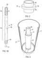
- a canister assembly (un-numbered) comprises part of a booster explosive 10.
- the canister assembly comprises a canister body 12 having a canister base 14 in which an open base passage 14a and a cap well mounting fixture 14b are formed.
- a cap well 20 is mounted on cap well mounting fixture 14b and is surmounted by a protective sleeve 28 along a portion of its length.
- Cast explosive 16 Contained within the body 12 of the canister assembly is a cast explosive 16, which, as is well known in the art, may be Pentolite or the like.
- Cast explosive 16 has formed therein a cavity (un-numbered) which is configured to receive cap well 20 and the protective sleeve 28, as more fully described below.
- Cast explosive 16 has also formed therein a fuse tunnel 22.
- a detonator 24 has connected to it a fuse 18, which may be shock tube or any other suitable fuse extending from the fuse end (unnumbered) of detonator 24 through base passage 14a, thence through fuse tunnel 22 and outwardly of fuse tunnel 22 at the top 16a of cast explosive 16, in the usual manner.
- Cap well 20 has a distal closed end 20a and a proximal open end 20b, the latter of which is securely mounted onto cap well mounting fixture 14b.
- the cap well itself may comprise a synthetic polymeric material (plastic) closed at one end and open at its opposite end to receive the detonator therein, as shown in the canister described in the above-mentioned U.S. Patent 9,115,963 .
- any suitable canister and cap well configuration is useable in the present invention.
- the canister body 12 and canister base 14 and, if present, an optional canister top may be made of molded plastic or any suitable material such as waxed or coated cardboard, plastic sheeting, or the like.
- Detonator 24 is disposed within cap well 20 with the explosive end section 24a of detonator 24 ( Figure 1B ) at or adjacent to the closed end 20a of cap well 20.
- detonator 24 is of conventional construction and is comprised of a shell 24b having the usual crimp 24c closing the open end of shell 24b, and a detonator tip 24d.
- Detonator 24 further has a firing train section 24e which contains, as is well known in the art, an electronic or pyrotechnic firing train. Firing train section 24e is the portion of the detonator 24 protected by protective sleeve 28.
- Detonator 24 which may be of conventional construction, is positioned within cap well 20 with detonator explosive charge 26 positioned at or immediately adjacent to the distal closed end 20a of cap well 20.
- a small air head space (not shown) may optionally be left between the tip 24d of detonator 20 and the distal closed end 20a of cap well 20.
- the canister assembly and cast booster explosive of the present invention may be made by any suitable manufacturing process.
- An efficient process is to mold from a suitable synthetic polymeric material canister body 12 integrally with fuse tunnel 22 and to separately mold cap well 20 from the same or a different synthetic polymeric material, as disclosed in the above-mentioned U.S. Patent 9,115,963 .
- Cap well 20, protective sleeve 28 and sleeve seal 34 are then mounted within canister body 12. Thereafter, a flowable explosive is introduced into canister body 12 and hardens into cast explosive 16. Normally, the detonator 24 and its fuse 18 are not inserted until the point of use, for obvious safety reasons.
- the shell 24b of detonator 24 is broken away at the explosive end section 24a thereof in order to show detonator explosive charge 26.
- a shock-absorbing barrier is comprised, in the illustrated embodiment, of a protective sleeve 28, which extends from the proximal open end 20b of cap well 20 and stops short of the portion of cap well 20 which encloses explosive end section 24a of detonator 24.
- the terminal end 28a ( Figure 1A ) of protective sleeve 28 stops short of detonator explosive charge 26 contained within explosive end section 24a.
- protective sleeve 28 extends to the proximal open end 20b of cap well 20.
- An annular air space is provided between the outside diameter of the cap well and the inside diameter of the protective sleeve.
- the protective sleeve snugly fitted about the exterior of the cap well may serve as the sole shock absorbing barrier, improved shock resistance is attained by a combination of a protective sleeve and an annular air space between the exterior of the cap well and the interior of the protective sleeve.
- the inside diameter D of protective sleeve 28 is greater than the outside diameter d of cap well 20 so that the width w of the annular air space is (D-d)/2.
- cap well 20 is tapered along its length to be of slightly smaller diameter at distal closed end 20a ( Figure 1 ) than at proximal open end 20b.
- the tapered inside diameter facilitates insertion of detonator 24 into cap well 20 from open end 20b of cap well 20.
- the identically tapered outside diameter d ( Figure 1A ) of cap well 20 results in the width w of the annular air space 32 gradually increasing in size from adjacent open end 20b to adjacent closed end 20a.
- the size range of width w may of course differ from one to another embodiment of the invention.
- width w ranges from about 0.05 inch (0.127 cm) to about 0.08 inch (0.203 cm), or from about 0.05 inch (0.127 cm) to about 0.075 inch (0.191 cm), or from about 0.052 inch (0.132 cm) to about 0.072 inch (0.183 cm).
- Water, soil and other foreign materials, as well as the bulk explosive slurry or emulsion, or cast explosive pentolite or the like, must be kept out of the annular air space if the air space is to provide effective shock wave attenuation. The annular air space is therefore sealed at both ends of the protective sleeve as described below.
- annular air space surrounding the cap well containing the detonator enhances the shock wave protection as compared to the protective sleeve snugly fitted around the cap well.
- a snugly-fitted protective sleeve or a protective sleeve which provides an annular air space is a much poorer transmission medium for explosive shock waves than would be a solid cast explosive such as Pentolite disposed in direct contact with the cap well.
- the annular air space 32 should be protected against infiltration by ground water, soil particles, particles of ammonium nitrate from the ANFO, etc., especially if the cast booster explosive is positioned within a borehole for a significant length of time before detonation. Such infiltration will greatly reduce or eliminate the shock-absorbing ability of the annular air space.
- the terminal end 28a of protective sleeve 28 is closed by a sleeve seal 34.
- Sleeve seal 34 is of generally annular configuration and may be formed of any material suitable for sealing against liquid or particulate infiltration, for example, sleeve seal 34 may be made of a suitable rubber or other natural or synthetic polymeric material. As seen in Figures 1A and 2 , sleeve seal 34 comprises a tubular body 34a from which an annular crown 34b extends longitudinally, and a ring 34c extends radially of tubular body 34a and rests on the terminal end 28a of protective sleeve 28. A portion of ring 34c at the right-hand side of Figure 1A is broken away to better show a portion of terminal end 28a of protective sleeve 28.
- Sleeve seal 34 is sufficiently compressible to form a tight force-fit seal to close the terminal end 28a of protective sleeve 28 to prevent infiltration of ground water, etc., into annular air space 32.
- sleeve seal 34 may comprise any suitable elastomeric material such as a water-resistant rubber such as that sold under the trademark NEOPRENE ® .
- NEOPRENE ® a water-resistant rubber
- the bottom of protective sleeve 28 is sealed by being firmly seated on canister base 14.
- the protective sleeve 28 may be a close fit about the outside wall of cap well 20 so as to substantially eliminate the annular air space 32.
- This embodiment is obtained by a force-fit of protective sleeve 28 about most of the exterior wall of cap well 20 stopping short of at least the portion of cap well 20 which encloses the explosive end section 24a of detonator 24.
- the protective sleeve alone is relied upon to provide attenuation of shock waves from prior adjacent explosions.
- protective sleeve 28 may be made of any suitable material, for example, any suitable metal such as brass or any suitable synthetic polymer (plastic) material, or wood, cardboard, etc., or combinations thereof.
- Protective sleeve 28, when made of brass, may be a seamless tube having a wall thickness of at least about 0.05 inch (0.127 centimeter), for example, from about 0.05 inch to about 0.06 inch (0.152 centimeter) or from about 0,05 inch to about 0.070 inch (0.178 centimeter).
- the length of protective sleeve 28 and the other exemplary dimensions given herein may of course vary depending on the specific dimensions of the cap well, the degree of desired shock wave protection, etc.
- the length of protective sleeve 28 may vary from about 2 inches (5.08 centimeters) to about 3 inches (7.62 centimeters) in length, and the outer diameter of protective sleeve 28 may be from about 0.7 inch (1.78 centimeters) to about 1 inch (2.54 centimeters).
- a tube as described above is simple to manufacture, obviously the protective sleeve, whether dimensioned to be a snug, close fit around the cap well or dimensioned to provide an annular air gap, may be of more complex design, e.g., it may comprise a multi-layer tube with layers of different materials, a coated tube, etc.
- the cap well may be positioned to extend along the central longitudinal axis of the canister so that the cap well and the detonator contained therein are equidistant from the canister wall in all directions. This results in the same degree of protection from shock waves by the surrounding body of cast explosive regardless of the orientation of the booster explosive to the source of the shock wave, i.e., to the location of a nearby explosive which is to be detonated before the booster charge of the invention.
- FIG 3 shows a central cap well booster explosive 10' with a cardboard canister body 12' broken away and cast booster explosive and detonator omitted for clarity of illustration.
- Cap well 20' is seen to be disposed along the central longitudinal axis of booster explosive 10' and the fuse tunnel (not shown in Figure 3 ) will of necessity be offset from the central longitudinal axis.
- a protective sleeve 28' extends from the bottom of the cap well 20' and stops short of the closed end 20a' of cap well 20' in order to leave unshielded by sleeve 28' the active section 20d' of cap well 20, that is, the portion of cap well 20' which houses the explosive end section of the detonator (not shown in Figure 3 ).
- Sleeve seal 34' seals the top of the protective sleeve 28' to prevent entry of foreign objects into the annular air space formed between the exterior of cap well 20' and protective sleeve 28'.
- a series of tests was conducted by suspending prototype test embodiments of booster explosives of the present invention in water spaced apart at different selected distances from a donor explosive charge.
- the donor explosive charges were suspended in the water at the same depth as the test embodiments, at about 6 feet (1.83 meters) below the surface.
- the donor charges comprised two 900 gram Pentolite charges, to provide a donor charge of 1,800 grams of Pentolite.
- Each of the test embodiments was configured so that the distance between the cap well (20, Figure 1 ) and the wall of the canister body (12, Figure 1 ) varied from 0.5 inch (1.27 centimeters) to 1.2 inches (3.05 centimeters).
- the test embodiments were not oriented rotationally to the donor charges during the tests.
- Both the donor charges and the test embodiments utilized electronic delay detonators.
- the tests were conducted by initiating both the donor and test embodiment detonators at the same time, with the donor charge delay detonator programmed to detonate while the test embodiment delay detonator was still counting down towards its detonation time. Those of the test embodiment detonators which were significantly damaged by the shock wave generated by the donor charge failed to initiate their associated explosive charges.
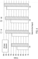
- test results are graphically shown in Figure 4 , which shows on the left-hand vertical axis the percentage of test embodiments which were not damaged by the shock wave engendered by detonation of the donor charges. (A single donor charge was used for a single test embodiment in each test.) The graph thus shows the percentage of test embodiment booster explosives which functioned properly, that is, which were not damaged by the donor explosive shock wave.
- the horizontal axis of the chart shows the distance in feet between the test embodiments and the donor charges. The indicated distances are center to center distances between the donor charge and the test embodiment.
- test embodiments identified as "SR" in the graph of Figure 4 are embodiments as described herein where there is no annular air space, i.e., the protective sleeve 28 fits snugly about the exterior of the cap well 20.
- the test embodiments identified in the graph of Figure 4 as "SR2" are in accordance with the illustrated embodiments of the present invention wherein the annular air space 32 ( Figure 1A ) is about 0.05 inch (0.13 centimeter) wide. That is, there is about 0.05 inch (0.13 centimeter) distance between the exterior wall of cap well 20 and the interior wall of protective sleeve 28.
- the protective sleeve 28 used in all test embodiments was a brass sleeve 0.73 inch (1.85 centimeters) in outer diameter with a wall thickness of 0.065 inch (0.165 centimeter).
- the brass sleeve was 2.7 inches (6.9 centimeters) in length, leaving the portion of the cap well which enclosed the explosive end section 24a of detonator 24 exposed, i.e., uncovered by protective sleeve 28.
- Each test embodiment utilized an electronic delay detonator sold under the trademark DigiShot ® by Dyno Nobel Inc., and programmed for a 1,500 millisecond delay.
- the delay detonator was 3.5 inches (8.9 centimeters) in length and had an explosive end about 1 inch (2.54 centimeters) in length which contained about 0.1 gram of lead azide initiator enclosed by a base charge comprised of about 0.8 gram of PETN.
- Each test embodiment comprised a booster explosive containing 450 grams of Pentolite in a plastic cylinder measuring about 5 inches (12.7 centimeters) in length and about 2 inches (5.1 centimeters) in diameter.
Landscapes
- Engineering & Computer Science (AREA)
- General Engineering & Computer Science (AREA)
- Manufacturing & Machinery (AREA)
- Chemical & Material Sciences (AREA)
- Organic Chemistry (AREA)
- Air Bags (AREA)
- Portable Nailing Machines And Staplers (AREA)
- Placing Or Removing Of Piles Or Sheet Piles, Or Accessories Thereof (AREA)
- Pressure Welding/Diffusion-Bonding (AREA)
- Shaping Metal By Deep-Drawing, Or The Like (AREA)
- Braking Systems And Boosters (AREA)
- Fuses (AREA)
Claims (14)
- Kanisteranordnung für einen gegossenen Verstärkungs-Sprengstoff, wobei die Kanisterbaugruppe aufweist: einen Kanisterkörper (12), der einen Kanisterinnenraum definiert und eine Kanisterbasis (14) aufweist, eine Kappenvertiefung (20) von allgemein röhrenförmiger Konfiguration, die innerhalb des Kanisterinnenraums angeordnet ist, wobei die Kappenvertiefung (20) eine Länge, einen Außendurchmesser, einen aktiven Abschnitt, der in einem distalen geschlossenen Ende (20a) endet, und ein proximales offenes Ende (20b) aufweist, wobei die Kappenvertiefung (20) so konfiguriert ist, dass sie darin einen Zünder (24) aufnimmt; undeine Schutzhülse (28), die über der Kappenvertiefung (20) sitzt,wobei die Schutzhülse (28) so konfiguriert ist, dass sie den aktiven Abschnitt der Kappenvertiefung (20) freilässt und einen größeren Abschnitt der Länge der Kappenvertiefung (20) umschließt.
- Kanisteranordnung nach Anspruch 1, wobei die Schutzhülse (28) einen Innendurchmesser aufweist, der größer ist als der Außendurchmesser der Kappenvertiefung (20), wodurch ein ringförmiger Kappenlochraum zwischen dem Innendurchmesser der Schutzhülse (28) und dem Außendurchmesser der Kappenvertiefung (20) definiert wird.
- Kanisteranordnung nach Anspruch 2, wobei die Schutzhülse (28) ein Anschlussende aufweist, das angrenzend an den aktiven Abschnitt der Kappenvertiefung (20) endet, wobei die Kanisteranordnung ferner eine Hülsenabdichtung (34) aufweist, die den ringförmigen Kappenlochraum am Anschlussende der Schutzhülse (28) verschließt.
- Kanisteranordnung nach Anspruch 2, wobei die Schutzhülse (28) ein dem Anschluss entgegengesetztes Basisende aufweist und wobei das Basisende der Schutzhülse (28) an der Kanisterbasis (14) angebracht ist, wodurch der ringförmige Raum der Kappenvertiefung am Basisende der Schutzhülse (28) abgedichtet wird.
- Kanisteranordnung nach Anspruch 2, wobei der ringförmige Raum der Kappenvertiefung eine Dicke von etwa 0,05 Zoll (0,127 cm) bis etwa 0,08 Zoll (0,203 cm) aufweist.
- Kanisteranordnung nach Anspruch 2, wobei die Schutzhülse (28) ein Rohr (35) mit einer Wandstärke von etwa 0,05 Zoll (0,127 Zentimeter) bis etwa 0,07 Zoll (0,178 Zentimeter) aufweist.
- Kanisteranordnung nach Anspruch 2, wobei die Schutzhülse (28) eine Länge von etwa 2 Zoll (5,08 Zentimeter) bis etwa 3 Zoll (7,62 Zentimeter) aufweist.
- Kanisteranordnung nach Anspruch 2, wobei die Schutzhülse (28) einen Außendurchmesser von etwa 0,7 Zoll (1,78 Zentimeter) bis etwa 1 Zoll (2,54 Zentimeter) aufweist.
- Kanisteranordnung nach Anspruch 2, wobei die Schutzhülse (28) ein Metallrohr (35) aufweist.
- Kanisteranordnung nach Anspruch 1, wobeidie Schutzhülse (28) ferner einen Innendurchmesser aufweist, der größer ist als der Außendurchmesser der Kappenvertiefung (20), wodurch ein ringförmiger Kappenlochraum zwischen dem Innendurchmesser der Schutzhülse (28) und dem Außendurchmesser der Kappenvertiefung (20) definiert wird;die Schutzhülse (28) eine Basis und ein gegenüberliegendes Anschlussende aufweist, wobei das Anschlussende angrenzend an den aktive Abschnitt der Kappenvertiefung (20) endet;die Kanisterbaugruppe ferner eine Hülsendichtung (34) aufweist, die an dem Anschlussende der Schutzhülse (28) angebracht ist, um den ringförmigen Raum des Kappenlochs an dem Anschlussende der Schutzhülse (28) abzudichten, und das Basisende der Schutzhülse (28) an der Kanisterbasis (14) angebracht ist, um den ringförmigen Raum der Kappenvertiefung an dem Basisende der Schutzhülse (28) abzudichten.
- Kanisteranordnung nach Anspruch 1 oder 10, ferner aufweisend einen gegossenen Verstärkungs-Sprengstoff, der im Inneren des Kanisters angeordnet ist.
- Kanisteranordnung nach Anspruch 11, ferner aufweisend einen Zünder (24), der in der Kappenvertiefung (20) angeordnet ist.
- Kanisteranordnung nach Anspruch 2, ferner aufweisend einen gegossenen Verstärkungs-Sprengstoff, der im Inneren des Kanisters angeordnet ist.
- Kanisteranordnung nach Anspruch 13, die ferner einen Zünder (24) aufweist, die in der Kappenvertiefung (20) angeordnet ist.
Applications Claiming Priority (2)
| Application Number | Priority Date | Filing Date | Title |
|---|---|---|---|
| US202062978595P | 2020-02-19 | 2020-02-19 | |
| PCT/US2021/018181 WO2021167886A1 (en) | 2020-02-19 | 2021-02-16 | Canister assembly with protected cap well and booster explosive comprising the same |
Publications (4)
| Publication Number | Publication Date |
|---|---|
| EP4107472A1 EP4107472A1 (de) | 2022-12-28 |
| EP4107472A4 EP4107472A4 (de) | 2024-03-06 |
| EP4107472C0 EP4107472C0 (de) | 2025-05-21 |
| EP4107472B1 true EP4107472B1 (de) | 2025-05-21 |
Family
ID=77391580
Family Applications (1)
| Application Number | Title | Priority Date | Filing Date |
|---|---|---|---|
| EP21756259.4A Active EP4107472B1 (de) | 2020-02-19 | 2021-02-16 | Kanisteranordnung mit geschützter verschlusskappe und damit versehener booster-sprengstoff |
Country Status (14)
| Country | Link |
|---|---|
| US (1) | US11473882B2 (de) |
| EP (1) | EP4107472B1 (de) |
| AU (1) | AU2021224538B2 (de) |
| BR (1) | BR112022016201A2 (de) |
| CA (1) | CA3166970A1 (de) |
| CL (1) | CL2022002244A1 (de) |
| CO (1) | CO2022011607A2 (de) |
| ES (1) | ES3035384T3 (de) |
| MA (1) | MA57760B1 (de) |
| MX (1) | MX2022010045A (de) |
| PE (1) | PE20221711A1 (de) |
| PL (1) | PL4107472T3 (de) |
| WO (1) | WO2021167886A1 (de) |
| ZA (1) | ZA202209738B (de) |
Families Citing this family (2)
| Publication number | Priority date | Publication date | Assignee | Title |
|---|---|---|---|---|
| CA3121248A1 (en) * | 2019-01-28 | 2020-08-06 | Detnet South Africa (Pty) Ltd | Detonator sensing arrangement |
| US12287183B2 (en) * | 2023-08-28 | 2025-04-29 | Aeci Mining Limited | Explosive booster |
Family Cites Families (51)
| Publication number | Priority date | Publication date | Assignee | Title |
|---|---|---|---|---|
| US2759418A (en) * | 1951-08-14 | 1956-08-21 | Allied Chem & Dye Corp | Frozen nitrogen tetroxide-hydrocarbon explosives |
| US3092025A (en) | 1960-08-11 | 1963-06-04 | Dow Chemical Co | Detonating device |
| US3183836A (en) | 1963-08-21 | 1965-05-18 | Trojan Powder Co | Canister for cast primer |
| US3276372A (en) * | 1965-04-28 | 1966-10-04 | Hercules Powder Co Ltd | Booster device |
| US3355053A (en) * | 1965-11-02 | 1967-11-28 | Sexton Can Co Inc | Metal can and closure therefor |
| US3407730A (en) | 1966-09-21 | 1968-10-29 | Trojan Powder Co | Retainer for holding a detonator in a detonator receptacle and explosive cartridge container containing the same |
| US3451341A (en) | 1967-09-22 | 1969-06-24 | Hercules Inc | Booster structure |
| US3437037A (en) | 1967-10-10 | 1969-04-08 | Hercules Inc | Fuse type initiator and booster system containing same |
| US3437038A (en) | 1967-10-10 | 1969-04-08 | Hercules Inc | Process and assembly for manufacture of cast boosters,and booster product |
| US3507218A (en) | 1968-07-03 | 1970-04-21 | Seispower Corp | Explosive container |
| US3604353A (en) | 1968-12-24 | 1971-09-14 | Hercules Inc | Cast booster assembly |
| US3831522A (en) | 1973-03-02 | 1974-08-27 | R Romney | Explosive booster and container therefor |
| AT339798B (de) | 1974-02-26 | 1977-11-10 | Hagenuck & Co Gmbh | Ubersprengsicherer schlagbolzenzunder |
| US3948177A (en) * | 1974-07-12 | 1976-04-06 | Hercules Incorporated | Self-disarming explosive cartridges |
| US4023494A (en) | 1975-11-03 | 1977-05-17 | Tyler Holding Company | Explosive container |
| US4178852A (en) | 1977-08-29 | 1979-12-18 | Atlas Powder Company | Delay actuated explosive device |
| US4335652A (en) * | 1979-02-26 | 1982-06-22 | E. I. Du Pont De Nemours & Company | Non-electric delay detonator |
| US4295424A (en) | 1979-04-24 | 1981-10-20 | Atlas Powder Company | Explosive container for cast primer |
| CA1140811A (en) | 1979-12-07 | 1983-02-08 | Ici Canada Inc. | Primer assembly having a delay cap/sensor element hermetically sealed in a shell unit |
| US4334476A (en) * | 1980-07-02 | 1982-06-15 | Mining Services International Corporation | Primer cup |
| IT1236493B (it) | 1981-02-27 | 1993-03-11 | Secr Defence Brit | Perfezionamento nei dispositivi di detonazione per cariche esplosive |
| CA1161302A (en) | 1981-06-26 | 1984-01-31 | Gordon K. Jorgenson | Primer assembly |
| US4485741A (en) | 1983-04-13 | 1984-12-04 | Apache Powder Company | Booster container with isolated and open cord tunnels |
| US4796533A (en) * | 1985-03-25 | 1989-01-10 | Eti Explosives Technologies International Inc. | Primer assembly |
| US4637312A (en) * | 1985-05-01 | 1987-01-20 | E. I. Du Pont De Nemours And Company | Explosive primer and carrier therefor |
| SE456528B (sv) * | 1986-02-17 | 1988-10-10 | Nobel Kemi Ab | Tendare |
| US4799428A (en) | 1987-04-06 | 1989-01-24 | Explosives Technologies International Inc. | Explosive primer unit for instantaneous initiation by low-energy detonating cord |
| US4776276A (en) * | 1987-05-06 | 1988-10-11 | Eti Explosives Technologies International Inc. | Cast explosive primer initiatable by low-energy detonating cord |
| US5522318A (en) | 1990-11-05 | 1996-06-04 | The Ensign-Bickford Company | Cushion element for detonators and the like; apparatus and method of assembly |
| AUPM861794A0 (en) | 1994-10-06 | 1994-10-27 | Ici Australia Operations Proprietary Limited | Explosives booster and primer |
| US5780764A (en) | 1996-01-11 | 1998-07-14 | The Ensign-Bickford Company | Booster explosive devices and combinations thereof with explosive accessory charges |
| US5747722A (en) * | 1996-01-11 | 1998-05-05 | The Ensign-Bickford Company | Detonators having multiple-line input leads |
| US5763816A (en) | 1996-07-26 | 1998-06-09 | Slurry Explosive Corporation | Explosive primer |
| US6311621B1 (en) | 1996-11-01 | 2001-11-06 | The Ensign-Bickford Company | Shock-resistant electronic circuit assembly |
| US6397752B1 (en) * | 1999-01-13 | 2002-06-04 | Schlumberger Technology Corporation | Method and apparatus for coupling explosive devices |
| GB2398094B (en) | 1999-07-22 | 2004-09-22 | Schlumberger Technology Corp | Components and methods for use with explosives |
| DE10084830T1 (de) | 1999-07-22 | 2003-01-30 | Schlumberger Technology Corp | Komponenten und Verfahren zur Verwendung mit Sprengstoffen |
| FR2832499B1 (fr) | 2001-11-19 | 2004-02-06 | Delta Caps Internat Dci | Module de commande electronique pour detonateur |
| US8127682B1 (en) | 2006-02-01 | 2012-03-06 | John Sonday | Cast booster using novel explosive core |
| DE602007008543D1 (de) | 2006-03-24 | 2010-09-30 | African Explosives Ltd | Detonation von sprengladungen |
| EP2013566B1 (de) | 2006-04-28 | 2015-03-04 | Orica Explosives Technology Pty Ltd | Drahtloser elektronischer verstärker und sprengverfahren |
| US7882785B2 (en) | 2006-08-14 | 2011-02-08 | The United States Of America As Represented By The Secretary Of The Navy | Demolition charge having multi-primed initiation system |
| US7472652B1 (en) | 2006-08-14 | 2009-01-06 | The United States Of America As Represented By The Secretary Of The Army | Demolition charge having multi-primed initiation system |
| US7882784B2 (en) | 2006-08-14 | 2011-02-08 | The United States Of America As Represented By The Secretary Of The Navy | Demolition charge having multi-primed initiation system |
| US7823508B2 (en) | 2006-08-24 | 2010-11-02 | Orica Explosives Technology Pty Ltd | Connector for detonator, corresponding booster assembly, and method of use |
| SE533526C2 (sv) | 2008-03-26 | 2010-10-19 | Jan-Aake Bengtsson | Användning av en krutladdad patron för att spräcka sten |
| SE534577C2 (sv) | 2010-02-03 | 2011-10-11 | Jan-Aake Bengtsson | Stenspräckpatron och tändkapsel |
| US20120192748A1 (en) | 2011-02-02 | 2012-08-02 | Eric Scheid | Coupling adapter |
| AU2012253612B2 (en) * | 2011-05-10 | 2015-10-29 | Dyno Nobel Inc. | Canisters with integral locking means and cast booster explosives comprising the same |
| EP3392601A1 (de) * | 2017-04-18 | 2018-10-24 | Maxamcorp Holding, S.L. | Zünderrückhaltesystem für verstärker |
| RU2691033C1 (ru) * | 2018-08-24 | 2019-06-07 | Акционерное общество "Новосибирский механический завод "Искра" | Промежуточный детонатор из эмульсионного взрывчатого состава |
-
2021
- 2021-02-16 WO PCT/US2021/018181 patent/WO2021167886A1/en not_active Ceased
- 2021-02-16 MA MA57760A patent/MA57760B1/fr unknown
- 2021-02-16 BR BR112022016201A patent/BR112022016201A2/pt unknown
- 2021-02-16 PE PE2022001757A patent/PE20221711A1/es unknown
- 2021-02-16 EP EP21756259.4A patent/EP4107472B1/de active Active
- 2021-02-16 MX MX2022010045A patent/MX2022010045A/es unknown
- 2021-02-16 CA CA3166970A patent/CA3166970A1/en active Pending
- 2021-02-16 AU AU2021224538A patent/AU2021224538B2/en active Active
- 2021-02-16 ES ES21756259T patent/ES3035384T3/es active Active
- 2021-02-16 US US17/176,846 patent/US11473882B2/en active Active
- 2021-02-16 PL PL21756259.4T patent/PL4107472T3/pl unknown
-
2022
- 2022-08-17 CO CONC2022/0011607A patent/CO2022011607A2/es unknown
- 2022-08-17 CL CL2022002244A patent/CL2022002244A1/es unknown
- 2022-08-31 ZA ZA2022/09738A patent/ZA202209738B/en unknown
Also Published As
| Publication number | Publication date |
|---|---|
| EP4107472C0 (de) | 2025-05-21 |
| EP4107472A1 (de) | 2022-12-28 |
| CA3166970A1 (en) | 2021-08-26 |
| US20210404778A1 (en) | 2021-12-30 |
| CO2022011607A2 (es) | 2022-08-30 |
| ZA202209738B (en) | 2023-03-29 |
| AU2021224538A1 (en) | 2022-08-25 |
| MA57760A1 (fr) | 2023-08-31 |
| CL2022002244A1 (es) | 2023-03-24 |
| PL4107472T3 (pl) | 2025-09-08 |
| AU2021224538B2 (en) | 2024-06-06 |
| WO2021167886A1 (en) | 2021-08-26 |
| MA57760B1 (fr) | 2023-12-29 |
| ES3035384T3 (en) | 2025-09-02 |
| BR112022016201A2 (pt) | 2022-10-04 |
| US11473882B2 (en) | 2022-10-18 |
| MX2022010045A (es) | 2022-10-10 |
| EP4107472A4 (de) | 2024-03-06 |
| PE20221711A1 (es) | 2022-11-02 |
Similar Documents
| Publication | Publication Date | Title |
|---|---|---|
| BR112019015882A2 (pt) | Carga moldada e sistema de suporte de pistola de perfuração exposta | |
| CA1161302A (en) | Primer assembly | |
| AU2009229575B2 (en) | Rock cracking assembly and method of making same | |
| FI57741C (fi) | Anordning foer initiering av spraengladdningar | |
| AU2011213319B2 (en) | Rock cracker cartridge and ignition capsule | |
| US4383484A (en) | Primer assembly | |
| EP4107472B1 (de) | Kanisteranordnung mit geschützter verschlusskappe und damit versehener booster-sprengstoff | |
| CN109813188B (zh) | 一种安全电子点火起爆件及安全电子点火起爆雷管 | |
| US4165691A (en) | Delay detonator and its use with explosive packaged boosters and cartridges | |
| US4776276A (en) | Cast explosive primer initiatable by low-energy detonating cord | |
| JPS6235039B2 (de) | ||
| CN100504280C (zh) | 爆破筒 | |
| OA20960A (en) | Canister assembly with protected cap well and booster explosive comprising the same. | |
| CA1331935C (en) | Multi-directional initiator for explosives | |
| CA1193909A (en) | Methods of and containers for igniting explosives | |
| FI69703B (fi) | Taendanordning | |
| US3587466A (en) | Relay charge with a fuse of weakened explosive power | |
| US3640222A (en) | Booster-cap assembly | |
| JPH0752080B2 (ja) | 発破補強方法 | |
| JPH0246557B2 (de) | ||
| NZ200635A (en) | Electro-magnetically actuated explosive primer assembly for use in vertical boreholes | |
| BG544Y1 (bg) | Съставен междинен детонаторен заряд |
Legal Events
| Date | Code | Title | Description |
|---|---|---|---|
| STAA | Information on the status of an ep patent application or granted ep patent |
Free format text: STATUS: THE INTERNATIONAL PUBLICATION HAS BEEN MADE |
|
| PUAI | Public reference made under article 153(3) epc to a published international application that has entered the european phase |
Free format text: ORIGINAL CODE: 0009012 |
|
| STAA | Information on the status of an ep patent application or granted ep patent |
Free format text: STATUS: REQUEST FOR EXAMINATION WAS MADE |
|
| 17P | Request for examination filed |
Effective date: 20220906 |
|
| AK | Designated contracting states |
Kind code of ref document: A1 Designated state(s): AL AT BE BG CH CY CZ DE DK EE ES FI FR GB GR HR HU IE IS IT LI LT LU LV MC MK MT NL NO PL PT RO RS SE SI SK SM TR |
|
| DAV | Request for validation of the european patent (deleted) | ||
| DAX | Request for extension of the european patent (deleted) | ||
| P01 | Opt-out of the competence of the unified patent court (upc) registered |
Effective date: 20230525 |
|
| A4 | Supplementary search report drawn up and despatched |
Effective date: 20240205 |
|
| RIC1 | Information provided on ipc code assigned before grant |
Ipc: F42B 3/26 20060101ALI20240130BHEP Ipc: F42B 3/24 20060101ALI20240130BHEP Ipc: F42B 3/10 20060101ALI20240130BHEP Ipc: F42B 3/28 20060101ALI20240130BHEP Ipc: F42B 3/08 20060101AFI20240130BHEP |
|
| GRAP | Despatch of communication of intention to grant a patent |
Free format text: ORIGINAL CODE: EPIDOSNIGR1 |
|
| STAA | Information on the status of an ep patent application or granted ep patent |
Free format text: STATUS: GRANT OF PATENT IS INTENDED |
|
| INTG | Intention to grant announced |
Effective date: 20250121 |
|
| GRAS | Grant fee paid |
Free format text: ORIGINAL CODE: EPIDOSNIGR3 |
|
| GRAA | (expected) grant |
Free format text: ORIGINAL CODE: 0009210 |
|
| STAA | Information on the status of an ep patent application or granted ep patent |
Free format text: STATUS: THE PATENT HAS BEEN GRANTED |
|
| AK | Designated contracting states |
Kind code of ref document: B1 Designated state(s): AL AT BE BG CH CY CZ DE DK EE ES FI FR GB GR HR HU IE IS IT LI LT LU LV MC MK MT NL NO PL PT RO RS SE SI SK SM TR |
|
| REG | Reference to a national code |
Ref country code: GB Ref legal event code: FG4D |
|
| REG | Reference to a national code |
Ref country code: CH Ref legal event code: EP |
|
| REG | Reference to a national code |
Ref country code: DE Ref legal event code: R096 Ref document number: 602021031158 Country of ref document: DE |
|
| REG | Reference to a national code |
Ref country code: IE Ref legal event code: FG4D |
|
| U01 | Request for unitary effect filed |
Effective date: 20250603 |
|
| U07 | Unitary effect registered |
Designated state(s): AT BE BG DE DK EE FI FR IT LT LU LV MT NL PT RO SE SI Effective date: 20250610 |
|
| P04 | Withdrawal of opt-out of the competence of the unified patent court (upc) registered |
Free format text: CASE NUMBER: APP_26682/2025 Effective date: 20250604 |
|
| REG | Reference to a national code |
Ref country code: GR Ref legal event code: EP Ref document number: 20250401211 Country of ref document: GR Effective date: 20250707 |
|
| REG | Reference to a national code |
Ref country code: ES Ref legal event code: FG2A Ref document number: 3035384 Country of ref document: ES Kind code of ref document: T3 Effective date: 20250902 |
|
| PG25 | Lapsed in a contracting state [announced via postgrant information from national office to epo] |
Ref country code: HR Free format text: LAPSE BECAUSE OF FAILURE TO SUBMIT A TRANSLATION OF THE DESCRIPTION OR TO PAY THE FEE WITHIN THE PRESCRIBED TIME-LIMIT Effective date: 20250521 |
|
| PG25 | Lapsed in a contracting state [announced via postgrant information from national office to epo] |
Ref country code: RS Free format text: LAPSE BECAUSE OF FAILURE TO SUBMIT A TRANSLATION OF THE DESCRIPTION OR TO PAY THE FEE WITHIN THE PRESCRIBED TIME-LIMIT Effective date: 20250821 |
|
| PG25 | Lapsed in a contracting state [announced via postgrant information from national office to epo] |
Ref country code: IS Free format text: LAPSE BECAUSE OF FAILURE TO SUBMIT A TRANSLATION OF THE DESCRIPTION OR TO PAY THE FEE WITHIN THE PRESCRIBED TIME-LIMIT Effective date: 20250921 |