EP4107448B1 - Wärmemanagementvorrichtung - Google Patents
Wärmemanagementvorrichtung Download PDFInfo
- Publication number
- EP4107448B1 EP4107448B1 EP21705253.9A EP21705253A EP4107448B1 EP 4107448 B1 EP4107448 B1 EP 4107448B1 EP 21705253 A EP21705253 A EP 21705253A EP 4107448 B1 EP4107448 B1 EP 4107448B1
- Authority
- EP
- European Patent Office
- Prior art keywords
- phase change
- heat exchange
- thermal management
- vehicle system
- exchange units
- Prior art date
- Legal status (The legal status is an assumption and is not a legal conclusion. Google has not performed a legal analysis and makes no representation as to the accuracy of the status listed.)
- Active
Links
Images


Classifications
-
- F—MECHANICAL ENGINEERING; LIGHTING; HEATING; WEAPONS; BLASTING
- F25—REFRIGERATION OR COOLING; COMBINED HEATING AND REFRIGERATION SYSTEMS; HEAT PUMP SYSTEMS; MANUFACTURE OR STORAGE OF ICE; LIQUEFACTION SOLIDIFICATION OF GASES
- F25B—REFRIGERATION MACHINES, PLANTS OR SYSTEMS; COMBINED HEATING AND REFRIGERATION SYSTEMS; HEAT PUMP SYSTEMS
- F25B5/00—Compression machines, plants or systems, with several evaporator circuits, e.g. for varying refrigerating capacity
- F25B5/02—Compression machines, plants or systems, with several evaporator circuits, e.g. for varying refrigerating capacity arranged in parallel
-
- F—MECHANICAL ENGINEERING; LIGHTING; HEATING; WEAPONS; BLASTING
- F25—REFRIGERATION OR COOLING; COMBINED HEATING AND REFRIGERATION SYSTEMS; HEAT PUMP SYSTEMS; MANUFACTURE OR STORAGE OF ICE; LIQUEFACTION SOLIDIFICATION OF GASES
- F25D—REFRIGERATORS; COLD ROOMS; ICE-BOXES; COOLING OR FREEZING APPARATUS NOT OTHERWISE PROVIDED FOR
- F25D16/00—Devices using a combination of a cooling mode associated with refrigerating machinery with a cooling mode not associated with refrigerating machinery
-
- F—MECHANICAL ENGINEERING; LIGHTING; HEATING; WEAPONS; BLASTING
- F41—WEAPONS
- F41H—ARMOUR; ARMOURED TURRETS; ARMOURED OR ARMED VEHICLES; MEANS OF ATTACK OR DEFENCE, e.g. CAMOUFLAGE, IN GENERAL
- F41H13/00—Means of attack or defence not otherwise provided for
- F41H13/0043—Directed energy weapons, i.e. devices that direct a beam of high energy content toward a target for incapacitating or destroying the target
- F41H13/005—Directed energy weapons, i.e. devices that direct a beam of high energy content toward a target for incapacitating or destroying the target the high-energy beam being a laser beam
-
- H—ELECTRICITY
- H10—SEMICONDUCTOR DEVICES; ELECTRIC SOLID-STATE DEVICES NOT OTHERWISE PROVIDED FOR
- H10W—GENERIC PACKAGES, INTERCONNECTIONS, CONNECTORS OR OTHER CONSTRUCTIONAL DETAILS OF DEVICES COVERED BY CLASS H10
- H10W40/00—Arrangements for thermal protection or thermal control
- H10W40/70—Fillings or auxiliary members in containers or in encapsulations for thermal protection or control
- H10W40/73—Fillings or auxiliary members in containers or in encapsulations for thermal protection or control for cooling by change of state
-
- B—PERFORMING OPERATIONS; TRANSPORTING
- B64—AIRCRAFT; AVIATION; COSMONAUTICS
- B64D—EQUIPMENT FOR FITTING IN OR TO AIRCRAFT; FLIGHT SUITS; PARACHUTES; ARRANGEMENT OR MOUNTING OF POWER PLANTS OR PROPULSION TRANSMISSIONS IN AIRCRAFT
- B64D13/00—Arrangements or adaptations of air-treatment apparatus for aircraft crew or passengers, or freight space
- B64D13/06—Arrangements or adaptations of air-treatment apparatus for aircraft crew or passengers, or freight space the air being conditioned
- B64D2013/0603—Environmental Control Systems
- B64D2013/0629—Environmental Control Systems with subsystems for cooling food, catering or special loads
-
- F—MECHANICAL ENGINEERING; LIGHTING; HEATING; WEAPONS; BLASTING
- F25—REFRIGERATION OR COOLING; COMBINED HEATING AND REFRIGERATION SYSTEMS; HEAT PUMP SYSTEMS; MANUFACTURE OR STORAGE OF ICE; LIQUEFACTION SOLIDIFICATION OF GASES
- F25B—REFRIGERATION MACHINES, PLANTS OR SYSTEMS; COMBINED HEATING AND REFRIGERATION SYSTEMS; HEAT PUMP SYSTEMS
- F25B2400/00—General features or devices for refrigeration machines, plants or systems, combined heating and refrigeration systems or heat-pump systems, i.e. not limited to a particular subgroup of F25B
- F25B2400/24—Storage receiver heat
Definitions
- This disclosure relates to a thermal management apparatus, vehicles incorporating thermal management apparatus, and to methods of thermal management employed in a thermal management apparatus.
- thermal management is used to ensure vehicle components and systems remain within their desired operating temperature range. Thermal management is particularly important for systems that have high peak energy consumption, and which operate on demand rather than with a steady energy throughput. Such systems have the potential to generate large amounts of heat in a short period of time. That heat can build up more rapidly than can be lost through natural heat dissipation or disposed of via a primary cooling system for the vehicle, such as the cooling system which deals with cooling the vehicle's interior or engines.
- LDEWs laser directed energy weapons
- LDEWs laser directed energy weapons
- the LDEW has high peak energy consumption and typically need to manage a significant amount of heat generated while the laser is in use over a short time period.
- disposing of excess heat generated during LDEW use can be a limiting factor on LDEW operation. This is particularly the case when the LDEW has different usage patterns according to operational requirements.
- thermal management apparatus In addition, as with all vehicle-mounted systems, there are restrictions on space and weight that can be dedicated to thermal management apparatus. Thus, there is a desire for a small, lightweight and adaptable thermal management apparatus.
- CN209787675U describes a cooling system comprising a phase change material energy store and ram air primary cooling source for an aircraft.
- US2012/327596 describes a thermal management system for a vehicle comprising a phase-change material arranged to cool an onboard system.
- EP2889551 A1 describes a multi-evaporator cooling system for use with a vehicle.
- EP2628680 A1 describes an environmental control system for use with a vehicle comprising phase change heat exchange units.
- US6205803 B1 describes a thermal control system for an avionics pod.
- thermal management apparatus for use with a vehicle according to claim 1.
- one or more of the phase change heat exchange units is thermally coupled to a primary cooling system of the vehicle to discharge heat thereto.
- each of the phase change heat exchange units is thermally coupled to a primary cooling system of the vehicle.
- all of the phase change heat exchange units are thermally coupled to a primary cooling system of the vehicle.
- this primary cooling system is an engine cooling system of the vehicle, and/or an interior cooling system of the vehicle.
- the primary cooling system comprises engine cooling and/or interior cooling of the vehicle.
- a thermal management apparatus that comprises a plurality of phase change heat exchange units, also known as phase change heat exchangers, that are thermally coupled with a system that requires thermal management takes advantage of the size and weight advantages of individual phase change heat exchange units, enabling flexibility in locating the individual units in a vehicle. Furthermore, flexibility in thermal management is achieved as it is possible to vary the operation of the phase change heat exchange units according to operational requirements of the system to which they are thermally connected.
- the phase change heat exchange units serve as a buffer between the system to which they are thermally connected and other cooling systems or equipment such as the primary cooling system of a vehicle.
- the thermal management apparatus comprises a manifold, operable to control delivery of heat from the vehicle system to the phase change heat exchange units.
- the manifold is operable to direct heat from the vehicle system to a subset of the phase change heat exchange units.
- the thermal management apparatus comprises a controller arranged to control the manifold.
- the controller is arranged to control the manifold to deliver heat from the vehicle system to two or more phase change heat exchange units simultaneously.
- the controller is arranged to control the manifold to deliver heat from the system to all of the phase change heat exchange units simultaneously.
- the controller is arranged to control the manifold to deliver heat from the system to two or more phase change heat exchange units in parallel, for example all of the phase change heat exchange units in parallel.
- the controller is arranged to control the manifold to deliver heat from the system to a first phase change heat exchange unit until that unit's capacity to receive heat is exhausted, then to control the manifold to deliver heat from the system to a second phase change heat exchange unit.
- the controller is arranged to control the manifold to deliver heat from the vehicle system to the phase change heat exchange units in sequence. In one example, the controller is arranged to control the manifold to deliver heat from the vehicle system to the phase change heat exchange units in sequence such that heat from the vehicle system is delivered to one first phase change heat exchange unit until that unit's capacity to receive heat is exhausted, then to the next. In one example, the controller is arranged to control the manifold to deliver heat from the vehicle system to the phase change heat exchange units in sequence such that heat from the vehicle system is delivered to one first phase change heat exchange unit until that unit's capacity to receive heat is exhausted, then to the next until all capacity of all the units to receive heat is exhausted. In one example, the controller is arranged to control the manifold to deliver heat from the vehicle system to phase change heat exchange units cyclically.
- phase change heat exchange units are operatively coupled to the controller to provide an indication of their capacity to receive heat.
- the thermal management apparatus comprises one or more temperature sensors arranged to provide temperature information to the controller. In one example, the thermal management apparatus comprises one or more temperature sensors that in use are operatively coupled to the vehicle system.
- the controller is in use arranged to communicate with the vehicle system through the system interface to control operation of the vehicle system.
- controller is arranged to control operation of the vehicle system according to the heat absorbing capacity of the phase change heat exchange units.
- controller is arranged to control operation of the vehicle system according to cool down ratio of the phase change heat exchange units.
- the controller is arranged to control operation of the vehicle system by inhibiting operation thereof while the temperature of the system is above an operating threshold.
- the controller is arranged to control operation of the vehicle system by inhibiting operation thereof while the heat absorbing capacity of the phase change heat exchange units is below a threshold capacity.
- the vehicle system comprises an electronics system. In one example, the vehicle system comprises a defence system. In one example, the vehicle system comprises a laser directed energy weapon.
- one or more of the phase change heat exchange units is thermally coupled to a heat sink on the vehicle. In one example, each of the phase change heat exchange units is thermally coupled to a heat sink on the vehicle. In one example, all of the phase change heat exchange units are thermally coupled to a heat sink on the vehicle.
- one or more of the phase change heat exchange units is thermally coupled to a structural component of the vehicle.
- each of the phase change heat exchange units is coupled to a structural component on the vehicle.
- all of the phase change heat exchange units are thermally coupled to a structural component on the vehicle.
- the structural component comprises a chassis of the vehicle.
- the structural component comprises an airframe of the vehicle.
- the structural component comprises a fuselage of the vehicle.
- a vehicle comprising the thermal management apparatus as set out herein.
- the vehicle comprises an aircraft. Aircraft are subject to restrictions on available space and weight that can be dedicated to thermal management apparatus, so a thermal management apparatus as described reduces problems of integration with the vehicle while enabling flexibility in operation to match to operational requirements of the system to which the phase change heat exchange units are thermally connected.
- the method comprises operating a manifold to control delivery of heat from the vehicle system to the phase change heat exchange units.
- the method comprises operating a manifold to direct heat from the vehicle system to a subset of the phase change heat exchange units.
- the method comprises operating a manifold to selectively control delivery of heat from the vehicle system to the phase change heat exchange units. In one example, the method comprises operating a manifold to selectively control delivery of heat from the vehicle system to individual phase change heat exchange units in the plurality of phase change heat exchange units.
- the method comprises operating a controller to control a manifold to deliver heat from the vehicle system to two or more phase change heat exchange units simultaneously.
- the method comprises operating a controller a manifold to deliver heat from the system to all of the phase change heat exchange units simultaneously.
- the method comprises operating a controller to control a manifold to deliver heat from the system to two or more phase change heat exchange units in parallel, for example all of the phase change heat exchange units in parallel.
- the method comprises operating a controller to control a manifold to deliver heat from the system to a first phase change heat exchange unit until that unit's capacity to receive heat is exhausted, then to control the manifold to deliver heat from the system to a second phase change heat exchange unit.
- the method comprises operating a controller to control a manifold to deliver heat from the vehicle system to the phase change heat exchange units in sequence. In one example, the method comprises operating a controller to control a manifold to deliver heat from the vehicle system to the phase change heat exchange units in sequence such that heat from the vehicle system is delivered to one first phase change heat exchange unit until that unit's capacity to receive heat is exhausted, then to the next. In one example, the method comprises operating a controller to control a manifold to deliver heat from the vehicle system to the phase change heat exchange units in sequence such that heat from the vehicle system is delivered to one first phase change heat exchange unit until that unit's capacity to receive heat is exhausted, then to the next until all capacity of all the units to receive heat is exhausted. In one example, the method comprises operating a controller to control a manifold to deliver heat from the vehicle system to phase change heat exchange units cyclically.
- the method comprises providing status information of the phase change heat exchange units to a controller to provide an indication of their capacity to receive heat.
- the method comprises providing temperature information of the vehicle system to a controller. In one example, the method comprises sensing the temperature of the vehicle system.
- the method comprises communicating with the vehicle system through to control operation of the vehicle system.
- the method comprises controlling operation of the vehicle system by inhibiting operation thereof while the temperature of the system is above an operating threshold.
- the method comprises controlling operation of the vehicle system by inhibiting operation thereof while the heat absorbing capacity of the phase change heat exchange units is below a threshold heat capacity.
- a thermal management apparatus for use with a vehicle is denoted as a whole by the reference numeral 100.
- the thermal management apparatus 100 comprises a plurality of phase change heat exchange units 101 that are thermally coupled with a vehicle system that requires thermal management, the plurality of phase change heat exchange units operable to remove heat from the vehicle system.
- the plurality of phase change heat exchange units operable to remove heat from the vehicle system.
- three phase change heat exchange units 101 are present.
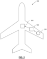
- FIG. 2 shows a vehicle 200 comprising the thermal management apparatus 100. While the vehicle 200 shown here comprises an aircraft, it would be readily appreciated that the present invention is applicable to other types of vehicles such as ships, land vehicles and so on.
- the vehicle 200 comprises various electronics systems that require thermal management to prevent overheating, including a laser directed energy weapon (LDEW) 201.
- LDEW laser directed energy weapon
- the LDEW 201 generates a significant amount of heat, which poses a limiting factor on LDEW operation due to the amount of time required for the LDEW 201 to cool down before it can be used again.
- the phase change heat exchange units 101 are thermally coupled to a primary cooling system 202 of the vehicle 200 to aid removal of heat from the phase change heat exchange units 101.
- the primary cooling system 202 may include active or forced cooling, alongside passive cooling elements such as specifically provisioned heat sinks (not shown) or by thermal coupling to one or more structural components on the vehicle 200.
- the primary cooling system 202 comprises engine cooling and/or interior cooling of the vehicle.
- the primary cooling system includes cooling systems pre-existing in the vehicle, or otherwise arranged for steady state/normal vehicle operations, i.e. not operations of the vehicle system that requires thermal management, in this example the LDEW 201.
- the thermal management apparatus 100 comprises a manifold 102, operable to control delivery of heat from the LDEW 201 to the phase change heat exchange units 101.
- the manifold 102 is operable to direct heat from the LDEW 201 to a subset of the phase change heat exchange units 101.
- phase change heat exchange unit units 101 Due to their ability to rapidly absorb the heat load generated by the LDEW 201, the phase change heat exchange unit units 101 provide a compact and effective cooling solution for laser applications.
- typical phase change heat exchange units have a 10:1 cool down ratio; that is, if the heat exchange unit's capacity to absorb heat is exhausted in 10 seconds, 100 seconds is required to re-cool the phase change heat exchange unit 101 so that it is again ready to absorb heat for another 10 seconds.
- the manifold 102 is operable to selectively control delivery of heat from the LDEW 201 to individual phase change heat exchange units 101 in the plurality of phase change heat exchange units 101.
- phase change heat exchange units 101 are operatively coupled to the controller 103 to provide information on their capacity to receive heat.
- the thermal management apparatus 100 comprises a controller 103 arranged to control the manifold 102, based on the phase change heat exchange units' capacity to receive heat.
- the controller 103 is arranged to control the manifold 102 to deliver heat from the vehicle system to one, two or more phase change heat exchange units 101 simultaneously.
- the heat generated by the LDEW 201 can be directed to the phase change heat exchange units 101 which have capacity to receive heat, i.e. are not currently re-cooling.
- the controller 103 may be arranged to control the manifold 102 to deliver heat from the system to a first phase change heat exchange unit 101 until that unit's capacity to receive heat is exhausted, then to control the manifold 102 to deliver heat from the system to a second phase change heat exchange unit 101, the second phase change heat exchange unit capable of receiving heat, and so on, in sequence, cyclically.
- This method of operation is suitable for enabling a longer burst of operation of the LDEW 201, with corresponding longer cooling delay.
- the manifold 102 is controllable to deliver heat from the LDEW 201 to the phase change heat exchange units 101 in parallel, so that as much heat as possible is absorbed as quickly as possible after each individual burst of operation of the LDEW 201.
Landscapes
- Engineering & Computer Science (AREA)
- Physics & Mathematics (AREA)
- General Engineering & Computer Science (AREA)
- Mechanical Engineering (AREA)
- Thermal Sciences (AREA)
- Chemical & Material Sciences (AREA)
- Combustion & Propulsion (AREA)
- Radar, Positioning & Navigation (AREA)
- Optics & Photonics (AREA)
- Remote Sensing (AREA)
- Control Of Temperature (AREA)
- Manufacturing & Machinery (AREA)
- Chemical Kinetics & Catalysis (AREA)
- Electrochemistry (AREA)
- General Chemical & Material Sciences (AREA)
- Food Preservation Except Freezing, Refrigeration, And Drying (AREA)
Claims (14)
- Wärmeverwaltungseinrichtung (100) zur Verwendung mit einem Fahrzeug (200), wobei die Einrichtung umfasst:eine Vielzahl von Phasenwechsel-Wärmetauschereinheiten (101), die thermisch mit einem Fahrzeugsystem (201) gekoppelt sind, das eine Wärmeverwaltung erfordert, wobei die Vielzahl von Phasenwechsel-Wärmetauschereinheiten dazu dient, Wärme aus dem Fahrzeugsystem abzuführen;einen Verteiler (102), der betriebsfähig ist, um die Wärmezufuhr vom Fahrzeugsystem zu den Phasenwechsel-Wärmetauschereinheiten zu regeln;gekennzeichnet durcheine Steuerung (103), die zum Steuern des Verteilers angeordnet ist;wobei die Phasenwechsel-Wärmetauschereinheiten operativ mit der Steuerung gekoppelt sind, um eine Anzeige ihrer Kapazität zur Aufnahme von Wärme bereitzustellen.
- Wärmeverwaltungseinrichtung nach Anspruch 1, wobei eine oder mehrere der Phasenwechsel-Wärmetauschereinheiten thermisch mit einem primären Kühlsystem (202) des Fahrzeugs gekoppelt sind.
- Wärmeverwaltungseinrichtung nach Anspruch 1 oder 2, wobei die Steuerung dazu dient, den Verteiler so zu steuern, dass Wärme vom Fahrzeugsystem parallel an zwei oder mehr Phasenwechsel-Wärmetauschereinheiten abgegeben wird.
- Wärmeverwaltungseinrichtung nach einem der Ansprüche 1 bis 3, wobei die Steuerung dazu dient, den Verteiler so zu steuern, dass er Wärme aus dem Fahrzeugsystem an eine erste Phasenwechsel-Wärmetauschereinheit liefert, bis die Wärmeaufnahmekapazität dieser Einheit erschöpft ist, und anschließend den Verteiler so zu steuern, dass er Wärme aus dem Fahrzeugsystem an eine zweite Phasenwechsel-Wärmetauschereinheit liefert.
- Wärmeverwaltungseinrichtung nach einem der Ansprüche 1 bis 4, wobei die Steuerung dazu dient, den Verteiler so zu steuern, dass er Wärme nacheinander vom Fahrzeugsystem an die Phasenwechsel-Wärmetauschereinheiten liefert.
- Wärmeverwaltungseinrichtung nach einem der Ansprüche 1 bis 5, die ferner einen oder mehrere Temperatursensoren (104) umfasst, die so angeordnet sind, dass sie der Steuerung Temperaturinformationen von mindestens einer der Phasenwechsel-Wärmetauschereinheiten (101) und/oder dem Fahrzeugsystem (201) bereitstellen.
- Wärmeverwaltungseinrichtung nach einem der Ansprüche 1 bis 6, wobei die Steuerung eine Systemschnittstelle umfasst, die bei Verwendung so angeordnet ist, dass sie mit dem Fahrzeugsystem kommuniziert, das eine Wärmeverwaltung erfordert.
- Wärmeverwaltungseinrichtung nach Anspruch 7, wobei die Steuerung bei Verwendung so eingerichtet ist, dass sie über die Systemschnittstelle mit dem Fahrzeugsystem kommuniziert, um den Betrieb des Fahrzeugsystems zu steuern.
- Wärmeverwaltungseinrichtung nach einem der Ansprüche 1 bis 8, wobei die Steuerung dazu eingerichtet ist, den Betrieb des Fahrzeugsystems gemäß mindestens einem der folgenden Parameter zu steuern: Wärmeabsorptionskapazität der Phasenwechsel-Wärmetauschereinheiten, Abkühlverhältnis der Phasenwechsel-Steuerungen und Temperatur des Fahrzeugsystems.
- Wärmeverwaltungseinrichtung nach einem der Ansprüche 1 bis 9, wobei die Steuerung dazu eingerichtet ist, den Betrieb des Fahrzeugsystems zu steuern, indem sie dessen Betrieb unterbindet, während die Temperatur des Fahrzeugsystems über einem Betriebsschwellenwert liegt.
- Wärmeverwaltungseinrichtung nach einem der Ansprüche 1 bis 10, wobei die Steuerung dazu eingerichtet ist, den Betrieb des Fahrzeugsystems zu steuern, indem sie dessen Betrieb unterbindet, während die Wärmeabsorptionskapazität der Phasenwechsel-Wärmetauschereinheiten unter einer Schwellenkapazität liegt.
- Wärmeverwaltungseinrichtung nach einem der vorstehenden Ansprüche, wobei das Fahrzeugsystem eine lasergesteuerte Energiewaffe umfasst.
- Fahrzeug (200), umfassend die Wärmeverwaltungseinrichtung nach einem der vorstehenden Ansprüche.
- Verfahren (300) zur Wärmeverwaltung unter Verwendung der Wärmeverwaltungseinrichtung nach einem der Ansprüche 1 bis 12.
Applications Claiming Priority (3)
| Application Number | Priority Date | Filing Date | Title |
|---|---|---|---|
| GB2002135.8A GB2592070B (en) | 2020-02-17 | 2020-02-17 | Thermal management apparatus |
| EP20275042.8A EP3865787A1 (de) | 2020-02-17 | 2020-02-17 | Wärmemanagementvorrichtung |
| PCT/GB2021/050303 WO2021165646A1 (en) | 2020-02-17 | 2021-02-10 | Thermal management apparatus |
Publications (3)
| Publication Number | Publication Date |
|---|---|
| EP4107448A1 EP4107448A1 (de) | 2022-12-28 |
| EP4107448C0 EP4107448C0 (de) | 2025-07-02 |
| EP4107448B1 true EP4107448B1 (de) | 2025-07-02 |
Family
ID=74595323
Family Applications (1)
| Application Number | Title | Priority Date | Filing Date |
|---|---|---|---|
| EP21705253.9A Active EP4107448B1 (de) | 2020-02-17 | 2021-02-10 | Wärmemanagementvorrichtung |
Country Status (6)
| Country | Link |
|---|---|
| US (1) | US12595937B2 (de) |
| EP (1) | EP4107448B1 (de) |
| JP (1) | JP7494309B2 (de) |
| IL (1) | IL295614A (de) |
| PL (1) | PL4107448T3 (de) |
| WO (1) | WO2021165646A1 (de) |
Families Citing this family (1)
| Publication number | Priority date | Publication date | Assignee | Title |
|---|---|---|---|---|
| US20250130022A1 (en) * | 2023-10-24 | 2025-04-24 | Applied Research Associates, Inc. | Laser system |
Family Cites Families (13)
| Publication number | Priority date | Publication date | Assignee | Title |
|---|---|---|---|---|
| US6205803B1 (en) | 1996-04-26 | 2001-03-27 | Mainstream Engineering Corporation | Compact avionics-pod-cooling unit thermal control method and apparatus |
| JP3251911B2 (ja) | 1998-12-21 | 2002-01-28 | 東京瓦斯株式会社 | 蓄熱(蓄冷)パネルおよび蓄熱(蓄冷)システムならびに該システムの蓄熱(蓄冷)方法 |
| US7854131B2 (en) | 2008-04-16 | 2010-12-21 | The Boeing Company | Thermal buffer system |
| WO2012135314A1 (en) | 2011-03-29 | 2012-10-04 | Rolls-Royce North American Technologies Inc. | Vehicle system |
| US9105951B2 (en) | 2011-06-22 | 2015-08-11 | Magna E-Car Systems Of America, Inc. | Thermal management system using a phase-change material for vehicle with electric traction motor |
| US20140109603A1 (en) * | 2011-12-29 | 2014-04-24 | Embraer S.A. | Integrated environmental control systems and methods for controlling environmental temperature of an enclosed space |
| FR3015780A3 (fr) | 2013-12-23 | 2015-06-26 | Renault Sa | Systeme de maintien en temperature d'une batterie. |
| US9657969B2 (en) * | 2013-12-30 | 2017-05-23 | Rolls-Royce Corporation | Multi-evaporator trans-critical cooling systems |
| JP6459714B2 (ja) | 2015-03-30 | 2019-01-30 | 株式会社デンソー | 制御装置及び車両用空調装置 |
| CN107152890B (zh) * | 2017-04-18 | 2019-01-11 | 南京航空航天大学 | 一种模块化复合型高能武器散热系统及其控制方法 |
| DE102017212309B3 (de) | 2017-07-19 | 2018-09-06 | Bayerische Motoren Werke Aktiengesellschaft | Kühlmittelkreislauf mit wenigstens zwei Kühlkreisen und einem Latentwärmespeicher |
| DE102017219814A1 (de) | 2017-11-08 | 2019-05-09 | Robert Bosch Gmbh | Batteriemodul mit einer Mehrzahl an Batteriezellen, Verwendung eines solchen Batteriemoduls und Verfahren zum Betrieb eines Batteriemoduls |
| CN209787675U (zh) | 2018-09-29 | 2019-12-13 | 南京工业大学 | 相变材料储能和冲压空气及燃油冷源的机载喷雾冷却系统 |
-
2021
- 2021-02-10 US US17/799,053 patent/US12595937B2/en active Active
- 2021-02-10 IL IL295614A patent/IL295614A/en unknown
- 2021-02-10 JP JP2022549529A patent/JP7494309B2/ja active Active
- 2021-02-10 EP EP21705253.9A patent/EP4107448B1/de active Active
- 2021-02-10 WO PCT/GB2021/050303 patent/WO2021165646A1/en not_active Ceased
- 2021-02-10 PL PL21705253.9T patent/PL4107448T3/pl unknown
Also Published As
| Publication number | Publication date |
|---|---|
| EP4107448C0 (de) | 2025-07-02 |
| JP2023517500A (ja) | 2023-04-26 |
| US12595937B2 (en) | 2026-04-07 |
| WO2021165646A1 (en) | 2021-08-26 |
| IL295614A (en) | 2022-10-01 |
| US20230068896A1 (en) | 2023-03-02 |
| EP4107448A1 (de) | 2022-12-28 |
| PL4107448T3 (pl) | 2025-09-08 |
| JP7494309B2 (ja) | 2024-06-03 |
Similar Documents
| Publication | Publication Date | Title |
|---|---|---|
| EP2920075B1 (de) | System und verfahren zur thermischen regelung von luftfahrzeugen | |
| EP2644508B1 (de) | System und Verfahren zur Kühlung elektrischer Komponenten | |
| EP2400828B1 (de) | Kühlung mit mehreren Flüssigkeitskreisläufen für Elektronik | |
| US20100313591A1 (en) | Adaptive heat sink for aircraft environmental control system | |
| US7954331B2 (en) | Thermally-balanced solid state cooling | |
| US10994857B2 (en) | Methods and apparatus to cool a vehicle heat source | |
| Mahefkey et al. | Thermal management challenges for future military aircraft power systems | |
| US20100071881A1 (en) | Cooling system for aircraft electric or electronic devices | |
| US5257757A (en) | Advanced hypersonic nosecap | |
| CN115042977B (zh) | 应用低温消耗性热沉的兆瓦级热负载机载热管理系统 | |
| EP4107448B1 (de) | Wärmemanagementvorrichtung | |
| EP0584920B1 (de) | Thermisches Regelsystem | |
| EP2805883B1 (de) | Luftfahrzeugkühlsystem | |
| US7433190B2 (en) | Liquid cooled electronic chassis having a plurality of phase change material reservoirs | |
| EP3865787A1 (de) | Wärmemanagementvorrichtung | |
| GB2592070A (en) | Thermal management apparatus | |
| EP2650218B1 (de) | Flugzeugklimasteuerungssystem und Verfahren zum Betreiben eines Flugzeugklimasteuerungssystems | |
| US20230112805A1 (en) | Systems and methods for cooling electronics | |
| AU2017402634B2 (en) | Integrated temperature control for multi-layer ceramics and method | |
| Hoang et al. | Multiple-evaporator loop heat pipe | |
| EP4163583B1 (de) | Gelenkte munition mit druckflüssigkeits-betätigungssystem mit wärmeaustausch | |
| US12477947B2 (en) | Powering sensor packages in moving platforms | |
| EP4293313A1 (de) | Kühlplattenwärmespeicher für hochlast-kurzdauerkühlung | |
| Chambliss et al. | Modular, thermal bus-to-radiator integral heat exchanger design for Space Station Freedom | |
| WO2016114739A1 (en) | A gun interface unit |
Legal Events
| Date | Code | Title | Description |
|---|---|---|---|
| STAA | Information on the status of an ep patent application or granted ep patent |
Free format text: STATUS: UNKNOWN |
|
| STAA | Information on the status of an ep patent application or granted ep patent |
Free format text: STATUS: THE INTERNATIONAL PUBLICATION HAS BEEN MADE |
|
| PUAI | Public reference made under article 153(3) epc to a published international application that has entered the european phase |
Free format text: ORIGINAL CODE: 0009012 |
|
| STAA | Information on the status of an ep patent application or granted ep patent |
Free format text: STATUS: REQUEST FOR EXAMINATION WAS MADE |
|
| 17P | Request for examination filed |
Effective date: 20220907 |
|
| AK | Designated contracting states |
Kind code of ref document: A1 Designated state(s): AL AT BE BG CH CY CZ DE DK EE ES FI FR GB GR HR HU IE IS IT LI LT LU LV MC MK MT NL NO PL PT RO RS SE SI SK SM TR |
|
| DAV | Request for validation of the european patent (deleted) | ||
| DAX | Request for extension of the european patent (deleted) | ||
| STAA | Information on the status of an ep patent application or granted ep patent |
Free format text: STATUS: EXAMINATION IS IN PROGRESS |
|
| 17Q | First examination report despatched |
Effective date: 20240228 |
|
| GRAP | Despatch of communication of intention to grant a patent |
Free format text: ORIGINAL CODE: EPIDOSNIGR1 |
|
| STAA | Information on the status of an ep patent application or granted ep patent |
Free format text: STATUS: GRANT OF PATENT IS INTENDED |
|
| INTG | Intention to grant announced |
Effective date: 20250401 |
|
| GRAS | Grant fee paid |
Free format text: ORIGINAL CODE: EPIDOSNIGR3 |
|
| GRAA | (expected) grant |
Free format text: ORIGINAL CODE: 0009210 |
|
| STAA | Information on the status of an ep patent application or granted ep patent |
Free format text: STATUS: THE PATENT HAS BEEN GRANTED |
|
| AK | Designated contracting states |
Kind code of ref document: B1 Designated state(s): AL AT BE BG CH CY CZ DE DK EE ES FI FR GB GR HR HU IE IS IT LI LT LU LV MC MK MT NL NO PL PT RO RS SE SI SK SM TR |
|
| REG | Reference to a national code |
Ref country code: GB Ref legal event code: FG4D |
|
| REG | Reference to a national code |
Ref country code: CH Ref legal event code: EP |
|
| REG | Reference to a national code |
Ref country code: DE Ref legal event code: R096 Ref document number: 602021033280 Country of ref document: DE |
|
| REG | Reference to a national code |
Ref country code: IE Ref legal event code: FG4D |
|
| U01 | Request for unitary effect filed |
Effective date: 20250723 |
|
| U07 | Unitary effect registered |
Designated state(s): AT BE BG DE DK EE FI FR IT LT LU LV MT NL PT RO SE SI Effective date: 20250729 |
|
| PG25 | Lapsed in a contracting state [announced via postgrant information from national office to epo] |
Ref country code: IS Free format text: LAPSE BECAUSE OF FAILURE TO SUBMIT A TRANSLATION OF THE DESCRIPTION OR TO PAY THE FEE WITHIN THE PRESCRIBED TIME-LIMIT Effective date: 20251102 |
|
| PG25 | Lapsed in a contracting state [announced via postgrant information from national office to epo] |
Ref country code: HR Free format text: LAPSE BECAUSE OF FAILURE TO SUBMIT A TRANSLATION OF THE DESCRIPTION OR TO PAY THE FEE WITHIN THE PRESCRIBED TIME-LIMIT Effective date: 20250702 |
|
| PG25 | Lapsed in a contracting state [announced via postgrant information from national office to epo] |
Ref country code: GR Free format text: LAPSE BECAUSE OF FAILURE TO SUBMIT A TRANSLATION OF THE DESCRIPTION OR TO PAY THE FEE WITHIN THE PRESCRIBED TIME-LIMIT Effective date: 20251003 |
|
| PG25 | Lapsed in a contracting state [announced via postgrant information from national office to epo] |
Ref country code: CZ Free format text: LAPSE BECAUSE OF FAILURE TO SUBMIT A TRANSLATION OF THE DESCRIPTION OR TO PAY THE FEE WITHIN THE PRESCRIBED TIME-LIMIT Effective date: 20250702 |
|
| PG25 | Lapsed in a contracting state [announced via postgrant information from national office to epo] |
Ref country code: RS Free format text: LAPSE BECAUSE OF FAILURE TO SUBMIT A TRANSLATION OF THE DESCRIPTION OR TO PAY THE FEE WITHIN THE PRESCRIBED TIME-LIMIT Effective date: 20251002 |
|
| PG25 | Lapsed in a contracting state [announced via postgrant information from national office to epo] |
Ref country code: ES Free format text: LAPSE BECAUSE OF FAILURE TO SUBMIT A TRANSLATION OF THE DESCRIPTION OR TO PAY THE FEE WITHIN THE PRESCRIBED TIME-LIMIT Effective date: 20250702 |
|
| U20 | Renewal fee for the european patent with unitary effect paid |
Year of fee payment: 6 Effective date: 20260121 |
|
| PG25 | Lapsed in a contracting state [announced via postgrant information from national office to epo] |
Ref country code: SM Free format text: LAPSE BECAUSE OF FAILURE TO SUBMIT A TRANSLATION OF THE DESCRIPTION OR TO PAY THE FEE WITHIN THE PRESCRIBED TIME-LIMIT Effective date: 20250702 |
|
| PGFP | Annual fee paid to national office [announced via postgrant information from national office to epo] |
Ref country code: GB Payment date: 20260121 Year of fee payment: 6 |
|
| PGFP | Annual fee paid to national office [announced via postgrant information from national office to epo] |
Ref country code: NO Payment date: 20260123 Year of fee payment: 6 |
|
| PGFP | Annual fee paid to national office [announced via postgrant information from national office to epo] |
Ref country code: TR Payment date: 20260127 Year of fee payment: 6 |