EP4163583B1 - Gelenkte munition mit druckflüssigkeits-betätigungssystem mit wärmeaustausch - Google Patents
Gelenkte munition mit druckflüssigkeits-betätigungssystem mit wärmeaustausch Download PDFInfo
- Publication number
- EP4163583B1 EP4163583B1 EP22200388.1A EP22200388A EP4163583B1 EP 4163583 B1 EP4163583 B1 EP 4163583B1 EP 22200388 A EP22200388 A EP 22200388A EP 4163583 B1 EP4163583 B1 EP 4163583B1
- Authority
- EP
- European Patent Office
- Prior art keywords
- heat exchange
- fluid
- compressible fluid
- guided munition
- path
- Prior art date
- Legal status (The legal status is an assumption and is not a legal conclusion. Google has not performed a legal analysis and makes no representation as to the accuracy of the status listed.)
- Active
Links
Images


Classifications
-
- F—MECHANICAL ENGINEERING; LIGHTING; HEATING; WEAPONS; BLASTING
- F42—AMMUNITION; BLASTING
- F42B—EXPLOSIVE CHARGES, e.g. FOR BLASTING, FIREWORKS, AMMUNITION
- F42B10/00—Means for influencing, e.g. improving, the aerodynamic properties of projectiles or missiles; Arrangements on projectiles or missiles for stabilising, steering, range-reducing, range-increasing or fall-retarding
- F42B10/32—Range-reducing or range-increasing arrangements; Fall-retarding means
- F42B10/48—Range-reducing, destabilising or braking arrangements, e.g. impact-braking arrangements; Fall-retarding means, e.g. balloons, rockets for braking or fall-retarding
- F42B10/50—Brake flaps, e.g. inflatable
-
- F—MECHANICAL ENGINEERING; LIGHTING; HEATING; WEAPONS; BLASTING
- F42—AMMUNITION; BLASTING
- F42B—EXPLOSIVE CHARGES, e.g. FOR BLASTING, FIREWORKS, AMMUNITION
- F42B15/00—Self-propelled projectiles or missiles, e.g. rockets; Guided missiles
- F42B15/34—Protection against overheating or radiation, e.g. heat shields; Additional cooling arrangements
-
- F—MECHANICAL ENGINEERING; LIGHTING; HEATING; WEAPONS; BLASTING
- F25—REFRIGERATION OR COOLING; COMBINED HEATING AND REFRIGERATION SYSTEMS; HEAT PUMP SYSTEMS; MANUFACTURE OR STORAGE OF ICE; LIQUEFACTION SOLIDIFICATION OF GASES
- F25B—REFRIGERATION MACHINES, PLANTS OR SYSTEMS; COMBINED HEATING AND REFRIGERATION SYSTEMS; HEAT PUMP SYSTEMS
- F25B9/00—Compression machines, plants or systems, in which the refrigerant is air or other gas of low boiling point
- F25B9/02—Compression machines, plants or systems, in which the refrigerant is air or other gas of low boiling point using Joule-Thompson effect; using vortex effect
-
- F—MECHANICAL ENGINEERING; LIGHTING; HEATING; WEAPONS; BLASTING
- F42—AMMUNITION; BLASTING
- F42B—EXPLOSIVE CHARGES, e.g. FOR BLASTING, FIREWORKS, AMMUNITION
- F42B10/00—Means for influencing, e.g. improving, the aerodynamic properties of projectiles or missiles; Arrangements on projectiles or missiles for stabilising, steering, range-reducing, range-increasing or fall-retarding
- F42B10/02—Stabilising arrangements
- F42B10/14—Stabilising arrangements using fins spread or deployed after launch, e.g. after leaving the barrel
- F42B10/20—Stabilising arrangements using fins spread or deployed after launch, e.g. after leaving the barrel deployed by combustion gas pressure, or by pneumatic or hydraulic forces
-
- F—MECHANICAL ENGINEERING; LIGHTING; HEATING; WEAPONS; BLASTING
- F42—AMMUNITION; BLASTING
- F42B—EXPLOSIVE CHARGES, e.g. FOR BLASTING, FIREWORKS, AMMUNITION
- F42B10/00—Means for influencing, e.g. improving, the aerodynamic properties of projectiles or missiles; Arrangements on projectiles or missiles for stabilising, steering, range-reducing, range-increasing or fall-retarding
- F42B10/32—Range-reducing or range-increasing arrangements; Fall-retarding means
- F42B10/48—Range-reducing, destabilising or braking arrangements, e.g. impact-braking arrangements; Fall-retarding means, e.g. balloons, rockets for braking or fall-retarding
- F42B10/52—Nose cones
-
- F—MECHANICAL ENGINEERING; LIGHTING; HEATING; WEAPONS; BLASTING
- F42—AMMUNITION; BLASTING
- F42B—EXPLOSIVE CHARGES, e.g. FOR BLASTING, FIREWORKS, AMMUNITION
- F42B10/00—Means for influencing, e.g. improving, the aerodynamic properties of projectiles or missiles; Arrangements on projectiles or missiles for stabilising, steering, range-reducing, range-increasing or fall-retarding
- F42B10/60—Steering arrangements
- F42B10/62—Steering by movement of flight surfaces
- F42B10/64—Steering by movement of flight surfaces of fins
-
- F—MECHANICAL ENGINEERING; LIGHTING; HEATING; WEAPONS; BLASTING
- F25—REFRIGERATION OR COOLING; COMBINED HEATING AND REFRIGERATION SYSTEMS; HEAT PUMP SYSTEMS; MANUFACTURE OR STORAGE OF ICE; LIQUEFACTION SOLIDIFICATION OF GASES
- F25B—REFRIGERATION MACHINES, PLANTS OR SYSTEMS; COMBINED HEATING AND REFRIGERATION SYSTEMS; HEAT PUMP SYSTEMS
- F25B2309/00—Gas cycle refrigeration machines
- F25B2309/02—Gas cycle refrigeration machines using the Joule-Thompson effect
Definitions
- the present disclosure relates to actuation of moveable components, e.g. for use in guided munitions.
- Heatsinks, phase change materials, thermal electric coolers, and cryogenic coolers can be used to cool certain, isolated, components in an electronic assembly, such as infrared sensors, or on infrared seekers to cool the seeker to bring the signal noise floor down such that normal temperature targets in the infrared bands can be visualized.
- cooling the infrared sensor does not cool all components in the electronics assembly, including those that are heatgenerating, such as electro optical infrared (EOIR) image processor, RF antenna, and RF processors, Canard Actuation System electronics, and the like. Accordingly, there remains a need in the art for cooling systems and methods to cool seeker electronics, for example to maintain a component temperature within the operating range of the electronics.
- EOIR electro optical infrared
- guided munitions may have active components requiring deployment during a mission, such as wings, canards, nose cone, and the like.
- active components such as wings, canards, nose cone, and the like.
- here is always a need in the art for improved systems and methods for actuating moveable components on the guided munition.
- US 4069744 discloses a gas metering orifice for decreasing gas consumption of pneumatic actuator.
- US 3390612 discloses a pneumatically operated power actuator.
- US 8269156 discloses a guidance control system for projectiles.
- the present invention provides a guided munition as claimed in claim 1 and a method of discharging a compressible fluid from an onboard reservoir into a body of a guided munition as claimed in claim 7.
- the reservoir can further include an actuated discharge valve and the actuation system can include a controller operatively connected to control the discharge valve to discharge the compressible fluid at a predetermined time.
- the fluid path can be configured to cool the heat exchange volume in the fluid path prior to entering the actuation path.
- the actuation system can include an exhaust outlet defined in the guided munition body in fluid communication with the actuation path, and configured to exhaust the compressible fluid from the actuation path to an ambient environment external to the guided munition body.
- the fluid path is configured to direct the compressible fluid from the throttling orifice outlet to the heat exchange volume and the actuation path is configured to direct the compressible fluid from the heat exchange volume toward a respective nose cone segment to move the nose cone segment from a stowed position to a deployed position.
- the actuation system can be included in a nose cone mounted the guided munition body.
- the fluid path can be configured to direct the compressible fluid from the throttling orifice outlet to the heat exchange volume and the actuation path can be configured to direct the compressible fluid from the heat exchange volume away from a respective nose cone segment to move the respective nose cone segment from a stowed position to a deployed position.
- the actuation system can be configured to be ejected from the guided munition body with the respective nose cone segment upon deployment of the respective nose cone segment.
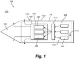
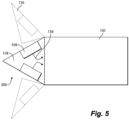
- FIG. 1 an illustrative view of an embodiment of a system in accordance with the disclosure is shown in Fig. 1 and is designated generally by reference character 100. Other arrangements are shown in Figs. 2-8 .
- Certain embodiments described herein can be used to remove heat from the source heat generating electronics to maintain the electronics components below max operating temperatures, operating more efficiently, and prevent failure due to over temperature situations.
- systems as disclosed herein can be used for actuation in guided munitions or other applications having one time use electronics.
- a moving platform 100 i.e., a guided munition
- a moving platform 100 can include a platform body 102, an electronics assembly 104 housed within the platform body 102, comprising an electronics component 106, and a thermal management system 200 (e.g., utilizing a Joule-Thompson cooler) configured to cool the electronics assembly 104.
- the thermal management system 200 can include a reservoir 108 housing a compressible fluid (e.g., any suitable gas or liquid as needed or desired) in a compressed state.
- the compressible fluid includes at least one of carbon dioxide, nitrogen, argon, neon and/or krypton. Any other suitable fluid, combination and/or mixture of the listed fluids is contemplated herein, for example fluids having a temperature range being below its inversion temperature as defined in a concept of operations (CONOP), and fluids having nonflammable nature.
- CONOP concept of operations
- the compressible fluid(s) can be tailored for specific CONOP thermal profiles, duration and thermal load required.
- the reservoir 108 can be a single storage container or any suitable number of storage containers (e.g., three as shown). In certain embodiments, the reservoir 108 can include a single container having a multi-celled structure. The reservoir 108 can include a release mechanism 110 for discharging the compressible fluid. In certain embodiments, the reservoir 108 can be configured to discharge the compressible fluid upon acceleration of the moving platform 100 (e.g., utilizing the high level of accelerations present within a gun launch), for example, setback, set-forward or balloting accelerations could be used in conjunction with mechanical features that could cause discharge the compressible fluid upon acceleration.
- the moving platform 100 e.g., utilizing the high level of accelerations present within a gun launch
- setback, set-forward or balloting accelerations could be used in conjunction with mechanical features that could cause discharge the compressible fluid upon acceleration.
- the release mechanism 110 can be or include a passive pressure release mechanism 110 configured to retain the compressible fluid at a first pressure (e.g., the highest pressure allowed by the passive pressure release mechanism) until a second predetermined pressure is reached (e.g., greater than the first pressure) and/or upon acceleration of the moving platform 100, at which time the compressible fluid can be discharged to a pressure that is lower than the pressure at which it was stored.
- a passive pressure release mechanism 110 can include a pierceable membrane, such as a frangible diaphragm, or a burst disk.
- the release mechanism 110 can be or include an actuated discharge valve, controllable by a thermal management system controller 112.
- the controller 112 can include machine readable instruction operative to control the discharge valve 110 to discharge the compressible fluid at a predetermined time, such as defined in a CONOP, for example, when the temperature gradient is needed the most.
- the release mechanism 110 can be or include an active pressure release mechanism, such as a squib or other suitable explosive.
- a blockage may be configured to retain the compressible fluid at a first predetermined pressure and configured to allow discharge of the compressible fluid upon detonation of the squib.
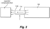
- a throttling orifice 114 is disposed in fluid communication with the reservoir 108 and is configured to expand the compressible fluid, such as shown in Fig. 2 , where expanding the compressible fluid produces a cooling effect to cool the compressible fluid.
- a heat exchange volume 116 is in fluid communication with the throttling orifice 114 to receive cooled compressible fluid from the throttling orifice 114.
- the cooled compressible fluid can be in fluid communication with the heat exchange volume 116 to cool the heat exchange volume 116 by convection
- the heat exchange volume 116 can be in thermal communication with the heat generating electronics component 106 (e.g., at or directly on, or near the component 106) of the electronics assembly 104 to remove heat from the heat generating electrics component 106 through conduction, e.g. heat conducts out of the heat generating component 106 to its surface and is convected away by the cooled, compressed gas either directly from the surface of the heat generating component 106 or a heat sink associated with it.
- the heat exchange volume 116 can be any suitable heat exchange volume, such as a multi fluid heat exchanger, a single fluid heat sink, or the like.
- the heat exchange volume 116 can be the reservoir 108 itself, such that as the compressible fluid is discharged, the cooled reservoir 108 can absorb ambient heat within the platform body 102.
- the reservoir 108 may be able to absorb aerothermal energy or near electronics or other heat producing components. The effect of allowing the reservoir 108 to absorb heat prior to initiation and release would be to increase the pressure of the compressible fluid within the reservoir 108. This could allow for tailoring of the Joule-Thompson cooling coefficient and/or or allowing for a lower storage pressure required at assembly.
- the heat exchange volume 116 can be or include a manifold array such that cooled compressible fluid can be directed to specific areas of the electronics assembly 104, such as electronics exhibiting higher temperatures.
- a manifold array such that cooled compressible fluid can be directed to specific areas of the electronics assembly 104, such as electronics exhibiting higher temperatures.
- different components 106 may experience temperature increases at different times, such that the manifold array is able to direct the cooled compressible fluid to each component as it is needed.
- multiple throttling orifices 114, and enlarged fluid channels may be included in the thermal management system 200 to allow for a multi-stage expansion approach for further cooling effects and to mitigate excess temperature increase in the compressible fluid.
- the thermal management system 200 can be in thermal communication with an outer shell 118 of the platform body 102.
- the heat exchange volume 116 can be in thermal communication with a cooling path 120 housing a working fluid, and configured to exchange heat between the working fluid and the compressible fluid in the heat exchange volume 116 while maintaining fluid isolation between the compressible fluid and the working fluid.
- the cooling path 120 can be or include a 3D printed, micro-machined or wire EDM flow channel.
- the cooling path 120 can be designed to increase the surface area in thermal contact with the compressible fluid and increase the thermal energy transfer between the working fluid and the compressible fluid.
- the compressible fluid can be directed through the cooling path, and over the heat exchange volume 116 to create a cooling effect that could induce a temperature differential and a thermal sink, thereby driving thermal transport through conductive means.
- the working fluid can be in thermal communication with the heat generating electronics component 106 to cool the heat generating electronics component 106 via any suitable means (e.g., as discussed above). While in Fig. 1 , the cooling path 120 is shown near, or surrounding the electronics assembly 104 and electronics components 106, it is contemplated the cooling path could be located elsewhere in the platform body 102 (e.g., separate from the electronics assembly 104 and heat generating electronics 106). Any suitable arrangement of the heat exchange volume 116 and cooling path 120 in relation to the electronics component 106 within the platform body 102, and any suitable combination of heat exchange volume structures is contemplated herein.
- the electronics assembly 104 may include certain, isolated electronics components 107, (e.g. an infrared (IR) sensor, a radio frequency (RF) seeker, a datalink, an RF communication module, or the like), which may generate less heat than components 106. Because the electronics components 107 typically generate little to negligible heat during use, components 107 can be separate from the electronics components 106 within assembly 104, or may be separate from the assembly 104 altogether. The electronics components 107 therefore may not need cooling from a thermal management system 200, or they may include separate systems for temperature maintenance, outside of thermal management system 200.
- IR infrared
- RF radio frequency
- the thermal management system 200 may act to cool the electronics components 107 in addition to cooling the other, heat generating components 106 in the electronics assembly 104, whether partially, wholly, intentionally, or incidentally.
- a temperature maintenance system for the components 107 can be aboard an aircraft that releases the guided munition 100 (e.g. in the rails).
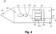
- the heat exchange volume 116 can be configured to direct, via any suitable means, the cooled compressible fluid in a first path 116a from a throttling orifice outlet 114b to and along a centerline 106-A of the heat generating electronics component 106, then outward from the centerline 106-A to any number of exhaust path outlets 122. Still with reference to Fig.
- the heat exchange volume 116 can be configured to direct, via any suitable means, the cooled compressible fluid in a second path 116b from the throttling orifice outlet 114b to a periphery 106-P of the heat generating electronics component 106, then inward to the centerline 106-A, then outward from the centerline to any number of exhaust path outlets 122.
- the heat exchange volume 116 can be configured to direct the cooled compressible fluid from the throttling orifice outlet 114b to a location 124 aft of the heat generating electronics component 106, then along the heat generating electronics component 106 to a location 126 forward of the heat generating electronics component 106 and to the exhaust path outlet 122.
- the heat exchange volume 116 can be configured to direct the cooled compressible fluid, via any suitable means, from the throttling orifice outlet 114b to via a third path 116c a location 126 forward of the electronics component 106, then along the electronic component 106 to a location 124 aft of the electronics component 106 via the exhaust path outlet 122.
- first and second paths 116a, 116b can be tailored to be used in the arrangement shown in Fig. 4 , even if not specifically shown herein.
- the forward location 126 can include housing at least the reservoir 108 of the thermal management system 200 in a nose cone 128 of the moving platform 100, such as shown in Fig.
- the system 200 can include multiple reservoirs 108, where at least one reservoir 108 is located in the nose cone 128 of the platform 100, and at least one reservoir 108 is located in the platform body 102. Any suitable combinations of reservoir arrangements and fluid paths in and through the moving platform 100 as shown and described is contemplated herein.
- the exhaust path outlet 122 can fluidly connect the heat exchange volume 116 to an ambient environment 130 external to the heat exchange volume via the exhaust path outlet.
- the exhaust path outlet 124 can be defined in the outer shell 118 of the platform body 102 to empty the spent compressible fluid to the ambient air 130 surrounding the platform 100 as it flies, for example as shown in Fig. 1 .
- the exhaust path outlet 122 in addition to or instead of the exhaust path outlet 122 defined in the platform body, the exhaust path outlet 122 can be defined in the nose cone 128 of the platform 100, as shown in Figs. 1 , 3 , 4 , and 6 .
- the exhaust path outlet 122 can be a passive port open to the ambient environment, a valved opening controllable by any suitable means, plugged with a device or material that ejects when over-pressured, covered with an acceleration initiated membrane, and/or other initiation methods.
- the exhaust path is used as an actuation system 300 configured to move a moveable component 136 mounted to the guided munition body 102, i.e. a nose cone segment.
- the actuation system 300 includes, in addition to the elements described above with respect to the thermal management system 200, an actuation path 138 (e.g., paths 116a, 116b, 116c) connecting the heat exchange volume 116 in fluid communication with the moveable component 136.
- the actuation path 138 is configured to supply pneumatic pressure to the moveable component 136 to move the moveable component 136 relative to the guided munition body 102, for example from a stowed position to a deployed position (e.g., a locked position and an in-flight position, respectively). Because the actuation system 300 utilizes the exhausted compressible fluid, the compressible fluid is directed, via any suitable path described herein, to cool the heat exchange volume 116 via a cooling path prior to entering the actuation path 138.
- the moveable component 136 is a nose cone segment mounted to the guided munition body 102.
- the compressible fluid is directed, via any suitable path, from the throttling orifice 114b outlet to the heat exchange volume 116, and toward the respective nose cone segment 136 to move the nose cone segment 136 outward from the guided munition body 102.
- the actuation system 300 can be included in the nose cone 128, where the compressible fluid can be directed from the throttling orifice outlet 114b to the heat exchange volume 116 and away from a respective nose cone segment 136 to move the respective nose cone segment 136 from the stowed position to the deployed position.
- the actuation system 300 can be configured to be ejected with the respective nose cone segment 136 upon actuation of the actuation system 300.
- the actuation system 300 can be included the guided munition body 102, where the compressible fluid can be directed from the throttling orifice outlet 114b to the heat exchange volume 116 and away towards the respective nose cone segment 136 to move the respective nose cone segment 136 from the stowed position to the deployed position, such that the compressible fluid is exhausted to the ambient environment 130 but the actuation system 300 is not ejected with the nose cone segment 136.
- the moveable component 136 can be or include at least one of a canard 136 in the CAS 132, and/or a wing 136.
- the actuation system 300 can be included in the platform body 102 such that the compressible fluid can be directed, via any suitable path, from the throttling orifice outlet 114b to the heat exchange volume 114 and toward the respective canard 136 to move the respective canard and/or wing 136 from the stowed position to the deployed position.
- the actuation system 300 can be included in any suitable position within the guided munition body 102 relative to the moveable component 136, such as shown in Fig.
- the reservoir 108 and throttling orifice 114 can be positioned forward of the moveable component 136, or, such as shown in Fig. 8 , the reservoir 108 throttling orifice 114 can be positioned aft the moveable component 136, for example.
- the present invention provides a method as claimed in claim 7.
- heatsinks or heat pipes can be used in conjunction with the systems as described herein, for example to transport heat to certain other components.
- active cooling techniques it may not be desirable to use active cooling techniques that require power, because in a guided munition, there may be a limited amount of power available to operate such active system. Additionally, active cooling system can, in certain instances, less efficient, and can contribute to the overall system thermal load.
- guided munition CONOPs can be relatively short, therefore the duration which the thermal load applied can be equally short. In this case, it may be desirable to utilize energy that can be added to the system prior to launch and/or be extracted from the launch or flight.
- Embodiments utilize the properties of the ideal gas law and Joule-Thomson effect to cool the electronics through the expansion of compressed gas.
- the high levels of acceleration experienced by a munition during a launch event can be used to initiate the release of the compressed gas.
- An external sink can be created for: heat to travel to through conduction, a cooling gas may move through a heatsink to remove heat through conduction, or may move across a heat producing electronic component to remove heat through conduction and convection. This process removes heat from the source in the electronics and keeps the components: below max operating temperatures, operating more efficiently, and from failing due to over temperature situations.
- Embodiments can be particularly useful in CONOPs in certain environments, such as a desert, where ambient temperatures are high and adding to that initial temperature.
- Other circumstances such as a hot gun environment (created by a hold fire order after a recent launch), could increase temperatures to where all or most of the operational temperature range is used up before launch.
- a high velocity launch could further add to the heat load applied to the electronics through supersonic shockwave thermal effects.
- Embodiments can therefore utilize a passive technique that can be used directly at the heat source to absorb and/or remove heat to drive thermal transport.
- Embodiments can employ the Joule-Thomson effect where the compressed gas is throttled through an orifice, below its inversion temperature, and expanded into a larger volume, creating a cooling effect.
- the cooled gas can be utilized to decrease the temperature of electronics through channeling it on or near the electronic components, or through the use of heat exchangers or heatsinks.
- the compressed gas is added to the munition from an external source, e.g.
- embodiments carry the compressed gas stored within the munition and release it into an open loop, exhausting externally.
- the intent of the cooling gas is to maintain the electronics in the munition at a cooled temperature that is within the operating temperature range and prevent the electronics from going into thermal runaway.
- Embodiments can maintain internal munition temperatures and electronics temperatures within an acceptable operating range with a potential to use less expensive automotive or commercial grade components.
Landscapes
- Engineering & Computer Science (AREA)
- General Engineering & Computer Science (AREA)
- Physics & Mathematics (AREA)
- Fluid Mechanics (AREA)
- Mechanical Engineering (AREA)
- Thermal Sciences (AREA)
- Chemical & Material Sciences (AREA)
- Aviation & Aerospace Engineering (AREA)
- Combustion & Propulsion (AREA)
- Cooling Or The Like Of Electrical Apparatus (AREA)
Claims (7)
- Gelenkte Munition (100), Folgendes umfassend:einen gelenkten Munitionskörper (102); undein Betätigungssystem, Folgendes umfassend: einen Behälter (108), der ein kompressibles Flüssigkeit in einem Druckzustand aufnimmt; einen Flüssigkeitsweg, der den Behälter in Flüssigkeitsverbindung mit einem Wärmeaustauschvolumen (116) verbindet; eine Drosselöffnung (114), die in dem Flüssigkeitsweg angeordnet und konfiguriert ist, um die kompressible Flüssigkeit auszudehnen; einen Betätigungsweg, der das Wärmeaustauschvolumen in Flüssigkeitsverbindung mit einer beweglichen Komponente (136) verbindet, die für eine Bewegung relativ zu dem gelenkten Munitionskörper montiert ist, wobei der Betätigungsweg konfiguriert ist, um der beweglichen Komponente pneumatischen Druck zuzuführen; dadurch gekennzeichnet, dass die bewegliche Komponente ein an dem gelenkten Munitionskörper montiertes Nasenkonussegment (136) beinhaltet.
- Gelenkte Munition (100) nach Anspruch 1, wobei der Flüssigkeitsweg konfiguriert ist, um das Wärmeaustauschvolumen (116) in dem Flüssigkeitsweg vor dem Eintritt in den Betätigungsweg zu kühlen.
- Gelenkte Munition (100) nach Anspruch 1 oder 2, wobei der Flüssigkeitsweg konfiguriert ist, um die kompressible Flüssigkeit von dem Auslass der Drosselöffnung (114) zu dem Wärmeaustauschvolumen (116) zu leiten, und der Betätigungsweg konfiguriert ist, um die kompressible Flüssigkeit von dem Wärmeaustauschvolumen zu dem Nasenkonussegment (136) zu leiten, um das Nasenkonussegment von einer verstauten Position zu einer entfalteten Position zu bewegen.
- Gelenkte Munition (100) nach Anspruch 1 oder 2, wobei das Betätigungssystem in einem Nasenkonus (128) beinhaltet ist, der an dem gelenkten Munitionskörper (102) montiert ist, wobei der Flüssigkeitsweg konfiguriert ist, um die kompressible Flüssigkeit von dem Auslass der Drosselöffnung (114) zu dem Wärmeaustauschvolumen zu leiten, und der Betätigungsweg konfiguriert ist, um die kompressible Flüssigkeit von dem Wärmeaustauschvolumen weg von dem Nasenkonussegment (136) zu leiten, um das Nasenkonussegment von einer verstauten Position zu einer entfalteten Position zu bewegen.
- Gelenkte Munition (100) nach Anspruch 4, wobei das Betätigungssystem konfiguriert ist, um mit dem Nasenkonussegment (136) bei der Entfaltung des Nasenkonussegments aus dem gelenkten Munitionskörper (102) ausgestoßen zu werden.
- System nach einem der vorhergehenden Ansprüche, wobei der Behälter (108) ferner ein betätigtes Auslassventil (110) beinhaltet und ferner umfassend eine Steuerung (112), die betriebsmäßig verbunden ist, um das Auslassventil zu steuern, um die kompressible Flüssigkeit zu einem vorbestimmten Zeitpunkt auszulassen.
- Verfahren, Folgendes umfassend:Auslassen einer kompressiblen Flüssigkeit aus einem Bordbehälter (108) in einen Körper einer gelenkten Munition (102), durch;Ausdehnen der kompressiblen Flüssigkeit durch eine Drosselöffnung (114);Strömenlassen der kompressiblen Flüssigkeit durch einen Flüssigkeitsweg von der Drosselöffnung zu einem Wärmeaustauschvolumen (116);Ablassen der kompressiblen Flüssigkeit aus dem Wärmeaustauschvolumen zu einem Betätigungsweg einer beweglichen Komponente (136) der gelenkten Munition (100); undBetätigen der beweglichen Komponente mit der abgelassenen kompressiblen Flüssigkeit;dadurch gekennzeichnet, dassBetätigen der beweglichen Komponente Betätigen eines an dem gelenkten Munitionskörper montierten Nasenkonussegments (136) beinhaltet.
Applications Claiming Priority (1)
| Application Number | Priority Date | Filing Date | Title |
|---|---|---|---|
| US17/450,449 US12007212B2 (en) | 2021-10-08 | 2021-10-08 | Joule-Thompson cooler actuation systems |
Publications (2)
| Publication Number | Publication Date |
|---|---|
| EP4163583A1 EP4163583A1 (de) | 2023-04-12 |
| EP4163583B1 true EP4163583B1 (de) | 2024-07-17 |
Family
ID=83689347
Family Applications (1)
| Application Number | Title | Priority Date | Filing Date |
|---|---|---|---|
| EP22200388.1A Active EP4163583B1 (de) | 2021-10-08 | 2022-10-07 | Gelenkte munition mit druckflüssigkeits-betätigungssystem mit wärmeaustausch |
Country Status (2)
| Country | Link |
|---|---|
| US (1) | US12007212B2 (de) |
| EP (1) | EP4163583B1 (de) |
Citations (1)
| Publication number | Priority date | Publication date | Assignee | Title |
|---|---|---|---|---|
| US7163176B1 (en) * | 2004-01-15 | 2007-01-16 | Raytheon Company | 2-D projectile trajectory correction system and method |
Family Cites Families (8)
| Publication number | Priority date | Publication date | Assignee | Title |
|---|---|---|---|---|
| US3390612A (en) * | 1965-07-06 | 1968-07-02 | Chandler Evans Inc | Dual stroke actuator |
| US4069744A (en) * | 1975-01-30 | 1978-01-24 | Texas Instruments Incorporated | Gas metering orifice for decreasing gas consumption of pneumatic actuator |
| DE3337194A1 (de) | 1983-10-13 | 1985-04-25 | Telefunken electronic GmbH, 7100 Heilbronn | Gehaeuse fuer ein optoelektronisches halbleiterbauelement |
| DE3432614A1 (de) | 1984-09-05 | 1986-03-13 | Rheinmetall GmbH, 4000 Düsseldorf | Flugkoerper |
| DE3838738A1 (de) | 1988-11-15 | 1990-05-23 | Diehl Gmbh & Co | Projektil mit ausklappbaren fluegeln |
| DE4226024C1 (de) | 1992-08-06 | 1993-07-15 | Bodenseewerk Geraetetechnik Gmbh, 7770 Ueberlingen, De | |
| US8269156B2 (en) | 2008-03-04 | 2012-09-18 | The Charles Stark Draper Laboratory, Inc. | Guidance control system for projectiles |
| US10018456B2 (en) | 2015-11-10 | 2018-07-10 | Raytheon Company | Multifunctional aerodynamic, propulsion, and thermal control system |
-
2021
- 2021-10-08 US US17/450,449 patent/US12007212B2/en active Active
-
2022
- 2022-10-07 EP EP22200388.1A patent/EP4163583B1/de active Active
Patent Citations (1)
| Publication number | Priority date | Publication date | Assignee | Title |
|---|---|---|---|---|
| US7163176B1 (en) * | 2004-01-15 | 2007-01-16 | Raytheon Company | 2-D projectile trajectory correction system and method |
Also Published As
| Publication number | Publication date |
|---|---|
| US20230114102A1 (en) | 2023-04-13 |
| US12007212B2 (en) | 2024-06-11 |
| EP4163583A1 (de) | 2023-04-12 |
Similar Documents
| Publication | Publication Date | Title |
|---|---|---|
| EP2644508B1 (de) | System und Verfahren zur Kühlung elektrischer Komponenten | |
| US7891298B2 (en) | Guided projectile | |
| EP4164354A1 (de) | Systeme und verfahren zur kühlung von elektronik | |
| US6422507B1 (en) | Smart bullet | |
| US6254031B1 (en) | Precision guidance system for aircraft launched bombs | |
| EP2412631B1 (de) | Kühlvorrichtung für eine Flüssigkeit mit hoher Temperatur, und Kühlverfahren für eine Flüssigkeit mit hoher Temperatur | |
| JP2021506539A (ja) | 広域火災を抑制するための耐火性空中機 | |
| US10018456B2 (en) | Multifunctional aerodynamic, propulsion, and thermal control system | |
| Mahefkey et al. | Thermal management challenges for future military aircraft power systems | |
| EP4163583B1 (de) | Gelenkte munition mit druckflüssigkeits-betätigungssystem mit wärmeaustausch | |
| US20150284080A1 (en) | Special forces replenishment vehicle | |
| US10942015B2 (en) | Actuation device for ejecting at least one removable part of a missile, particularly a nose | |
| US5218165A (en) | Pneumatic separation device | |
| EP1917495B1 (de) | Ausstossbare aerodynamische stabilisierungs- und steuerungsvorrichtung | |
| US11866204B2 (en) | Thermal control system for reentry vehicles | |
| EP2650218A1 (de) | Flugzeugwärmesteuerungssystem und Verfahren für den Betrieb eines Flugzeugwärmesteuerungssystems | |
| US5125596A (en) | Fluid shielded movable strut for missile and rocket thrust vector control | |
| JP6239724B1 (ja) | 飛翔体 | |
| US9115964B2 (en) | Integral injection thrust vector control with booster attitude control system | |
| JP2025526382A (ja) | 吹出し冷却用途向け水系ポリマーネットワーク | |
| US11346615B2 (en) | Multi-function thermal absorber and isolator using liquid-to-gas phase change material | |
| EP3286522B1 (de) | Projektil und gefechtskopf und abschusssystem dafür | |
| Harwell et al. | Cryogenic heat pipe experiment-Flight performance onboard a sounding rocket | |
| FRIEDMAN et al. | Ballistic-missile research with athena | |
| JP2002277199A (ja) | 飛翔体 |
Legal Events
| Date | Code | Title | Description |
|---|---|---|---|
| PUAI | Public reference made under article 153(3) epc to a published international application that has entered the european phase |
Free format text: ORIGINAL CODE: 0009012 |
|
| STAA | Information on the status of an ep patent application or granted ep patent |
Free format text: STATUS: THE APPLICATION HAS BEEN PUBLISHED |
|
| AK | Designated contracting states |
Kind code of ref document: A1 Designated state(s): AL AT BE BG CH CY CZ DE DK EE ES FI FR GB GR HR HU IE IS IT LI LT LU LV MC ME MK MT NL NO PL PT RO RS SE SI SK SM TR |
|
| STAA | Information on the status of an ep patent application or granted ep patent |
Free format text: STATUS: REQUEST FOR EXAMINATION WAS MADE |
|
| 17P | Request for examination filed |
Effective date: 20231012 |
|
| RBV | Designated contracting states (corrected) |
Designated state(s): AL AT BE BG CH CY CZ DE DK EE ES FI FR GB GR HR HU IE IS IT LI LT LU LV MC ME MK MT NL NO PL PT RO RS SE SI SK SM TR |
|
| GRAP | Despatch of communication of intention to grant a patent |
Free format text: ORIGINAL CODE: EPIDOSNIGR1 |
|
| STAA | Information on the status of an ep patent application or granted ep patent |
Free format text: STATUS: GRANT OF PATENT IS INTENDED |
|
| INTG | Intention to grant announced |
Effective date: 20240213 |
|
| RIN1 | Information on inventor provided before grant (corrected) |
Inventor name: BIBEAU, CRAIG Inventor name: GRAHAM, JASON |
|
| GRAS | Grant fee paid |
Free format text: ORIGINAL CODE: EPIDOSNIGR3 |
|
| GRAA | (expected) grant |
Free format text: ORIGINAL CODE: 0009210 |
|
| STAA | Information on the status of an ep patent application or granted ep patent |
Free format text: STATUS: THE PATENT HAS BEEN GRANTED |
|
| AK | Designated contracting states |
Kind code of ref document: B1 Designated state(s): AL AT BE BG CH CY CZ DE DK EE ES FI FR GB GR HR HU IE IS IT LI LT LU LV MC ME MK MT NL NO PL PT RO RS SE SI SK SM TR |
|
| REG | Reference to a national code |
Ref country code: CH Ref legal event code: EP |
|
| REG | Reference to a national code |
Ref country code: DE Ref legal event code: R096 Ref document number: 602022004612 Country of ref document: DE |
|
| REG | Reference to a national code |
Ref country code: IE Ref legal event code: FG4D |
|
| REG | Reference to a national code |
Ref country code: LT Ref legal event code: MG9D |
|
| REG | Reference to a national code |
Ref country code: NL Ref legal event code: MP Effective date: 20240717 |
|
| PG25 | Lapsed in a contracting state [announced via postgrant information from national office to epo] |
Ref country code: PT Free format text: LAPSE BECAUSE OF FAILURE TO SUBMIT A TRANSLATION OF THE DESCRIPTION OR TO PAY THE FEE WITHIN THE PRESCRIBED TIME-LIMIT Effective date: 20241118 |
|
| REG | Reference to a national code |
Ref country code: AT Ref legal event code: MK05 Ref document number: 1704514 Country of ref document: AT Kind code of ref document: T Effective date: 20240717 |
|
| PG25 | Lapsed in a contracting state [announced via postgrant information from national office to epo] |
Ref country code: NL Free format text: LAPSE BECAUSE OF FAILURE TO SUBMIT A TRANSLATION OF THE DESCRIPTION OR TO PAY THE FEE WITHIN THE PRESCRIBED TIME-LIMIT Effective date: 20240717 |
|
| PG25 | Lapsed in a contracting state [announced via postgrant information from national office to epo] |
Ref country code: PT Free format text: LAPSE BECAUSE OF FAILURE TO SUBMIT A TRANSLATION OF THE DESCRIPTION OR TO PAY THE FEE WITHIN THE PRESCRIBED TIME-LIMIT Effective date: 20241118 Ref country code: NL Free format text: LAPSE BECAUSE OF FAILURE TO SUBMIT A TRANSLATION OF THE DESCRIPTION OR TO PAY THE FEE WITHIN THE PRESCRIBED TIME-LIMIT Effective date: 20240717 |
|
| PG25 | Lapsed in a contracting state [announced via postgrant information from national office to epo] |
Ref country code: NO Free format text: LAPSE BECAUSE OF FAILURE TO SUBMIT A TRANSLATION OF THE DESCRIPTION OR TO PAY THE FEE WITHIN THE PRESCRIBED TIME-LIMIT Effective date: 20241017 |
|
| PG25 | Lapsed in a contracting state [announced via postgrant information from national office to epo] |
Ref country code: GR Free format text: LAPSE BECAUSE OF FAILURE TO SUBMIT A TRANSLATION OF THE DESCRIPTION OR TO PAY THE FEE WITHIN THE PRESCRIBED TIME-LIMIT Effective date: 20241018 Ref country code: FI Free format text: LAPSE BECAUSE OF FAILURE TO SUBMIT A TRANSLATION OF THE DESCRIPTION OR TO PAY THE FEE WITHIN THE PRESCRIBED TIME-LIMIT Effective date: 20240717 Ref country code: PL Free format text: LAPSE BECAUSE OF FAILURE TO SUBMIT A TRANSLATION OF THE DESCRIPTION OR TO PAY THE FEE WITHIN THE PRESCRIBED TIME-LIMIT Effective date: 20240717 |
|
| PG25 | Lapsed in a contracting state [announced via postgrant information from national office to epo] |
Ref country code: BG Free format text: LAPSE BECAUSE OF FAILURE TO SUBMIT A TRANSLATION OF THE DESCRIPTION OR TO PAY THE FEE WITHIN THE PRESCRIBED TIME-LIMIT Effective date: 20240717 |
|
| PG25 | Lapsed in a contracting state [announced via postgrant information from national office to epo] |
Ref country code: LV Free format text: LAPSE BECAUSE OF FAILURE TO SUBMIT A TRANSLATION OF THE DESCRIPTION OR TO PAY THE FEE WITHIN THE PRESCRIBED TIME-LIMIT Effective date: 20240717 |
|
| PG25 | Lapsed in a contracting state [announced via postgrant information from national office to epo] |
Ref country code: AT Free format text: LAPSE BECAUSE OF FAILURE TO SUBMIT A TRANSLATION OF THE DESCRIPTION OR TO PAY THE FEE WITHIN THE PRESCRIBED TIME-LIMIT Effective date: 20240717 Ref country code: IS Free format text: LAPSE BECAUSE OF FAILURE TO SUBMIT A TRANSLATION OF THE DESCRIPTION OR TO PAY THE FEE WITHIN THE PRESCRIBED TIME-LIMIT Effective date: 20241117 |
|
| PG25 | Lapsed in a contracting state [announced via postgrant information from national office to epo] |
Ref country code: HR Free format text: LAPSE BECAUSE OF FAILURE TO SUBMIT A TRANSLATION OF THE DESCRIPTION OR TO PAY THE FEE WITHIN THE PRESCRIBED TIME-LIMIT Effective date: 20240717 |
|
| PG25 | Lapsed in a contracting state [announced via postgrant information from national office to epo] |
Ref country code: RS Free format text: LAPSE BECAUSE OF FAILURE TO SUBMIT A TRANSLATION OF THE DESCRIPTION OR TO PAY THE FEE WITHIN THE PRESCRIBED TIME-LIMIT Effective date: 20241017 Ref country code: ES Free format text: LAPSE BECAUSE OF FAILURE TO SUBMIT A TRANSLATION OF THE DESCRIPTION OR TO PAY THE FEE WITHIN THE PRESCRIBED TIME-LIMIT Effective date: 20240717 |
|
| PG25 | Lapsed in a contracting state [announced via postgrant information from national office to epo] |
Ref country code: RS Free format text: LAPSE BECAUSE OF FAILURE TO SUBMIT A TRANSLATION OF THE DESCRIPTION OR TO PAY THE FEE WITHIN THE PRESCRIBED TIME-LIMIT Effective date: 20241017 Ref country code: PL Free format text: LAPSE BECAUSE OF FAILURE TO SUBMIT A TRANSLATION OF THE DESCRIPTION OR TO PAY THE FEE WITHIN THE PRESCRIBED TIME-LIMIT Effective date: 20240717 Ref country code: NO Free format text: LAPSE BECAUSE OF FAILURE TO SUBMIT A TRANSLATION OF THE DESCRIPTION OR TO PAY THE FEE WITHIN THE PRESCRIBED TIME-LIMIT Effective date: 20241017 Ref country code: LV Free format text: LAPSE BECAUSE OF FAILURE TO SUBMIT A TRANSLATION OF THE DESCRIPTION OR TO PAY THE FEE WITHIN THE PRESCRIBED TIME-LIMIT Effective date: 20240717 Ref country code: IS Free format text: LAPSE BECAUSE OF FAILURE TO SUBMIT A TRANSLATION OF THE DESCRIPTION OR TO PAY THE FEE WITHIN THE PRESCRIBED TIME-LIMIT Effective date: 20241117 Ref country code: HR Free format text: LAPSE BECAUSE OF FAILURE TO SUBMIT A TRANSLATION OF THE DESCRIPTION OR TO PAY THE FEE WITHIN THE PRESCRIBED TIME-LIMIT Effective date: 20240717 Ref country code: GR Free format text: LAPSE BECAUSE OF FAILURE TO SUBMIT A TRANSLATION OF THE DESCRIPTION OR TO PAY THE FEE WITHIN THE PRESCRIBED TIME-LIMIT Effective date: 20241018 Ref country code: FI Free format text: LAPSE BECAUSE OF FAILURE TO SUBMIT A TRANSLATION OF THE DESCRIPTION OR TO PAY THE FEE WITHIN THE PRESCRIBED TIME-LIMIT Effective date: 20240717 Ref country code: ES Free format text: LAPSE BECAUSE OF FAILURE TO SUBMIT A TRANSLATION OF THE DESCRIPTION OR TO PAY THE FEE WITHIN THE PRESCRIBED TIME-LIMIT Effective date: 20240717 Ref country code: BG Free format text: LAPSE BECAUSE OF FAILURE TO SUBMIT A TRANSLATION OF THE DESCRIPTION OR TO PAY THE FEE WITHIN THE PRESCRIBED TIME-LIMIT Effective date: 20240717 Ref country code: AT Free format text: LAPSE BECAUSE OF FAILURE TO SUBMIT A TRANSLATION OF THE DESCRIPTION OR TO PAY THE FEE WITHIN THE PRESCRIBED TIME-LIMIT Effective date: 20240717 |
|
| PG25 | Lapsed in a contracting state [announced via postgrant information from national office to epo] |
Ref country code: SM Free format text: LAPSE BECAUSE OF FAILURE TO SUBMIT A TRANSLATION OF THE DESCRIPTION OR TO PAY THE FEE WITHIN THE PRESCRIBED TIME-LIMIT Effective date: 20240717 Ref country code: DK Free format text: LAPSE BECAUSE OF FAILURE TO SUBMIT A TRANSLATION OF THE DESCRIPTION OR TO PAY THE FEE WITHIN THE PRESCRIBED TIME-LIMIT Effective date: 20240717 Ref country code: RO Free format text: LAPSE BECAUSE OF FAILURE TO SUBMIT A TRANSLATION OF THE DESCRIPTION OR TO PAY THE FEE WITHIN THE PRESCRIBED TIME-LIMIT Effective date: 20240717 |
|
| REG | Reference to a national code |
Ref country code: DE Ref legal event code: R097 Ref document number: 602022004612 Country of ref document: DE |
|
| PG25 | Lapsed in a contracting state [announced via postgrant information from national office to epo] |
Ref country code: EE Free format text: LAPSE BECAUSE OF FAILURE TO SUBMIT A TRANSLATION OF THE DESCRIPTION OR TO PAY THE FEE WITHIN THE PRESCRIBED TIME-LIMIT Effective date: 20240717 |
|
| PG25 | Lapsed in a contracting state [announced via postgrant information from national office to epo] |
Ref country code: CZ Free format text: LAPSE BECAUSE OF FAILURE TO SUBMIT A TRANSLATION OF THE DESCRIPTION OR TO PAY THE FEE WITHIN THE PRESCRIBED TIME-LIMIT Effective date: 20240717 |
|
| PG25 | Lapsed in a contracting state [announced via postgrant information from national office to epo] |
Ref country code: SK Free format text: LAPSE BECAUSE OF FAILURE TO SUBMIT A TRANSLATION OF THE DESCRIPTION OR TO PAY THE FEE WITHIN THE PRESCRIBED TIME-LIMIT Effective date: 20240717 |
|
| PLBE | No opposition filed within time limit |
Free format text: ORIGINAL CODE: 0009261 |
|
| STAA | Information on the status of an ep patent application or granted ep patent |
Free format text: STATUS: NO OPPOSITION FILED WITHIN TIME LIMIT |
|
| 26N | No opposition filed |
Effective date: 20250422 |
|
| PG25 | Lapsed in a contracting state [announced via postgrant information from national office to epo] |
Ref country code: MC Free format text: LAPSE BECAUSE OF FAILURE TO SUBMIT A TRANSLATION OF THE DESCRIPTION OR TO PAY THE FEE WITHIN THE PRESCRIBED TIME-LIMIT Effective date: 20240717 |
|
| PG25 | Lapsed in a contracting state [announced via postgrant information from national office to epo] |
Ref country code: LU Free format text: LAPSE BECAUSE OF NON-PAYMENT OF DUE FEES Effective date: 20241007 Ref country code: BE Free format text: LAPSE BECAUSE OF NON-PAYMENT OF DUE FEES Effective date: 20241031 |
|
| REG | Reference to a national code |
Ref country code: BE Ref legal event code: MM Effective date: 20241031 |
|
| PG25 | Lapsed in a contracting state [announced via postgrant information from national office to epo] |
Ref country code: SE Free format text: LAPSE BECAUSE OF FAILURE TO SUBMIT A TRANSLATION OF THE DESCRIPTION OR TO PAY THE FEE WITHIN THE PRESCRIBED TIME-LIMIT Effective date: 20240717 |
|
| PGFP | Annual fee paid to national office [announced via postgrant information from national office to epo] |
Ref country code: FR Payment date: 20250923 Year of fee payment: 4 |
|
| PG25 | Lapsed in a contracting state [announced via postgrant information from national office to epo] |
Ref country code: IE Free format text: LAPSE BECAUSE OF NON-PAYMENT OF DUE FEES Effective date: 20241007 |
|
| REG | Reference to a national code |
Ref country code: GB Ref legal event code: 732E Free format text: REGISTERED BETWEEN 20251023 AND 20251029 |
|
| REG | Reference to a national code |
Ref country code: DE Ref legal event code: R081 Ref document number: 602022004612 Country of ref document: DE Owner name: RAYTHEON COMPANY, ARLINGTON, US Free format text: FORMER OWNER: SIMMONDS PRECISION PRODUCTS, INC., VERGENNES, VT, US |
|
| PGFP | Annual fee paid to national office [announced via postgrant information from national office to epo] |
Ref country code: DE Payment date: 20250923 Year of fee payment: 4 |
|
| PG25 | Lapsed in a contracting state [announced via postgrant information from national office to epo] |
Ref country code: CY Free format text: LAPSE BECAUSE OF FAILURE TO SUBMIT A TRANSLATION OF THE DESCRIPTION OR TO PAY THE FEE WITHIN THE PRESCRIBED TIME-LIMIT; INVALID AB INITIO Effective date: 20221007 Ref country code: IT Free format text: LAPSE BECAUSE OF FAILURE TO SUBMIT A TRANSLATION OF THE DESCRIPTION OR TO PAY THE FEE WITHIN THE PRESCRIBED TIME-LIMIT Effective date: 20240717 |
|
| PG25 | Lapsed in a contracting state [announced via postgrant information from national office to epo] |
Ref country code: HU Free format text: LAPSE BECAUSE OF FAILURE TO SUBMIT A TRANSLATION OF THE DESCRIPTION OR TO PAY THE FEE WITHIN THE PRESCRIBED TIME-LIMIT; INVALID AB INITIO Effective date: 20221007 |