EP4105534A1 - Verbinderbaugruppe - Google Patents
Verbinderbaugruppe Download PDFInfo
- Publication number
- EP4105534A1 EP4105534A1 EP21461553.6A EP21461553A EP4105534A1 EP 4105534 A1 EP4105534 A1 EP 4105534A1 EP 21461553 A EP21461553 A EP 21461553A EP 4105534 A1 EP4105534 A1 EP 4105534A1
- Authority
- EP
- European Patent Office
- Prior art keywords
- connector
- parts
- fluid
- fluid flow
- connector part
- Prior art date
- Legal status (The legal status is an assumption and is not a legal conclusion. Google has not performed a legal analysis and makes no representation as to the accuracy of the status listed.)
- Pending
Links
Images


Classifications
-
- F—MECHANICAL ENGINEERING; LIGHTING; HEATING; WEAPONS; BLASTING
- F16—ENGINEERING ELEMENTS AND UNITS; GENERAL MEASURES FOR PRODUCING AND MAINTAINING EFFECTIVE FUNCTIONING OF MACHINES OR INSTALLATIONS; THERMAL INSULATION IN GENERAL
- F16L—PIPES; JOINTS OR FITTINGS FOR PIPES; SUPPORTS FOR PIPES, CABLES OR PROTECTIVE TUBING; MEANS FOR THERMAL INSULATION IN GENERAL
- F16L21/00—Joints with sleeve or socket
- F16L21/002—Sleeves or nipples for pipes of the same diameter; Reduction pieces
-
- F—MECHANICAL ENGINEERING; LIGHTING; HEATING; WEAPONS; BLASTING
- F16—ENGINEERING ELEMENTS AND UNITS; GENERAL MEASURES FOR PRODUCING AND MAINTAINING EFFECTIVE FUNCTIONING OF MACHINES OR INSTALLATIONS; THERMAL INSULATION IN GENERAL
- F16L—PIPES; JOINTS OR FITTINGS FOR PIPES; SUPPORTS FOR PIPES, CABLES OR PROTECTIVE TUBING; MEANS FOR THERMAL INSULATION IN GENERAL
- F16L21/00—Joints with sleeve or socket
- F16L21/02—Joints with sleeve or socket with elastic sealing rings between pipe and sleeve or between pipe and socket, e.g. with rolling or other prefabricated profiled rings
- F16L21/022—Joints with sleeve or socket with elastic sealing rings between pipe and sleeve or between pipe and socket, e.g. with rolling or other prefabricated profiled rings used with sleeves or nipples for pipes of the same diameter, or with reduction pieces
-
- F—MECHANICAL ENGINEERING; LIGHTING; HEATING; WEAPONS; BLASTING
- F16—ENGINEERING ELEMENTS AND UNITS; GENERAL MEASURES FOR PRODUCING AND MAINTAINING EFFECTIVE FUNCTIONING OF MACHINES OR INSTALLATIONS; THERMAL INSULATION IN GENERAL
- F16L—PIPES; JOINTS OR FITTINGS FOR PIPES; SUPPORTS FOR PIPES, CABLES OR PROTECTIVE TUBING; MEANS FOR THERMAL INSULATION IN GENERAL
- F16L21/00—Joints with sleeve or socket
- F16L21/08—Joints with sleeve or socket with additional locking means
-
- F—MECHANICAL ENGINEERING; LIGHTING; HEATING; WEAPONS; BLASTING
- F16—ENGINEERING ELEMENTS AND UNITS; GENERAL MEASURES FOR PRODUCING AND MAINTAINING EFFECTIVE FUNCTIONING OF MACHINES OR INSTALLATIONS; THERMAL INSULATION IN GENERAL
- F16L—PIPES; JOINTS OR FITTINGS FOR PIPES; SUPPORTS FOR PIPES, CABLES OR PROTECTIVE TUBING; MEANS FOR THERMAL INSULATION IN GENERAL
- F16L27/00—Adjustable joints, Joints allowing movement
- F16L27/10—Adjustable joints, Joints allowing movement comprising a flexible connection only, e.g. for damping vibrations
- F16L27/1012—Flanged joints
-
- F—MECHANICAL ENGINEERING; LIGHTING; HEATING; WEAPONS; BLASTING
- F16—ENGINEERING ELEMENTS AND UNITS; GENERAL MEASURES FOR PRODUCING AND MAINTAINING EFFECTIVE FUNCTIONING OF MACHINES OR INSTALLATIONS; THERMAL INSULATION IN GENERAL
- F16L—PIPES; JOINTS OR FITTINGS FOR PIPES; SUPPORTS FOR PIPES, CABLES OR PROTECTIVE TUBING; MEANS FOR THERMAL INSULATION IN GENERAL
- F16L37/00—Couplings of the quick-acting type
- F16L37/08—Couplings of the quick-acting type in which the connection between abutting or axially overlapping ends is maintained by locking members
- F16L37/12—Couplings of the quick-acting type in which the connection between abutting or axially overlapping ends is maintained by locking members using hooks, pawls or other movable or insertable locking members
- F16L37/138—Couplings of the quick-acting type in which the connection between abutting or axially overlapping ends is maintained by locking members using hooks, pawls or other movable or insertable locking members using an axially movable sleeve
-
- F—MECHANICAL ENGINEERING; LIGHTING; HEATING; WEAPONS; BLASTING
- F16—ENGINEERING ELEMENTS AND UNITS; GENERAL MEASURES FOR PRODUCING AND MAINTAINING EFFECTIVE FUNCTIONING OF MACHINES OR INSTALLATIONS; THERMAL INSULATION IN GENERAL
- F16L—PIPES; JOINTS OR FITTINGS FOR PIPES; SUPPORTS FOR PIPES, CABLES OR PROTECTIVE TUBING; MEANS FOR THERMAL INSULATION IN GENERAL
- F16L41/00—Branching pipes; Joining pipes to walls
- F16L41/02—Branch units, e.g. made in one piece, welded, riveted
- F16L41/021—T- or cross-pieces
Definitions
- the present disclosure relates to a connector assembly for connecting components to form a fluid flow conduit.
- Connector parts may be secured together by a form fit or friction fit and provided with seals around the join to prevent leakage. Often connector parts are connected by pushing one connector part into the other and then securing the connection by means of a clamp around the outside of the area where the connector parts join.
- a valve is used in a system.
- the valve is provided to regulate the flow of fluid through the pipes of the system and is therefore provided in the flow path(s).
- a valve will generally have one or more connector parts defining fluid inlets to, and fluid outlets from the valve. These are arranged to be fluidly connected to the fluid flow lines of the system in which the valve is used so that when the valve is open, a flow passage or conduit is defined from a system line, through an inlet defined by a valve connector part, through the valve, through an outlet defined by a connector part of the valve and into a system line connected to the outlet.
- water may be provided from a supply to a tank via a valve and/or from the tank to an end user or as overflow via a valve.
- the valve needs to be securely and fluidly connected by connector parts to the lines from the supply, to the tank and from the tank to the end user/overflow.
- the connection between the valve and the lines must be fluid-tight to prevent leakage.
- a first connector part is designed to have a slightly smaller diameter than the opposite connector part such that the smaller connector part can be pushed into the larger connector part.
- Seals e.g. O-ring seals, may be provided in the area inside the larger connector part, or on the outside of the smaller connector part, where the two parts overlap to ensure a tight fight. A clamp is then secured around the overlapping area to ensure a secure connection.
- connections are provided in constrained areas or are limited by the shape and configuration of the system part, such that it is not easy, or sometimes not possible, to connect the connector parts by pushing one into the other and it is then not possible to secure the clamp around a push-fit connection as required.
- valves have recently been designed having several ports around the valve that need to be connected to cooperating connector parts at different angles e.g. at e.g. 90 degree separation. It is not possible to connect all ports at the same time by the push-fit connection conventionally used.
- a connector assembly comprising: a first connector part and a second connector part, each connector part defining a fluid flow passage therethrough configured to together define a fluid flow conduit when the first and second parts are connected together, the connector assembly further comprising an extension part mounted around one of the first and the second connector parts, the extension part arranged to move relative to the connector part around which it is mounted to extend across an interface area between the first connector part and the second connector part and to bridge the first and second connector parts when the first and second connector parts are brought to meet each other to define the fluid conduit.
- the extension part may be a sleeve arranged to slide relative to the connector part around which it is mounted to overlap the other of the first and second connector parts.
- Sealing means may be provided on an outer surface of one or both of the first and second connector parts to provide a seal between the connector part(s) and the extension part.
- the interface area preferably includes a gap between the first and second connector parts, and may be defined by the first and second connector parts abutting against each other.
- the first connector part and/or the second connector part may be provided with means for engaging a fluid port of a fluid system component, in use.
- a clamp may be provided, configured to be mounted over the extension part when the first and second connector parts together define the fluid conduit.
- a fluid system such as a water system, comprising a valve arranged in a fluid flow path to regulate the flow of fluid therethrough, the valve connected to the fluid flow path by means of a connector assembly as defined above.
- the valve may have a plurality of ports to be connected to fluid lines of the system, and comprising a corresponding plurality of such connector assemblies to connect the ports to the fluid lines.
- a connector assembly comprises a first connector part 1, which may, for example, be a connector piece of a valve 10, and a connector part 2, which may be, for example, a connector piece of a tank 20, where the valve 10 is provided in a fluid path to regulate flow of fluid to and/or from the tank 20.
- a connector part 1 which may, for example, be a connector piece of a valve 10
- a connector part 2 which may be, for example, a connector piece of a tank 20, where the valve 10 is provided in a fluid path to regulate flow of fluid to and/or from the tank 20.
- the first and second connector parts 1, 2 To connect the valve 10 into the fluid path it is, therefore, necessary to connect the first and second connector parts 1, 2 together to define a fluid flow conduit.
- one of the connector parts here the first connector part 1 has a smaller diameter than the other connector part 2. The parts are connected by pushing the first connector part 1 into the second connector part 2 as indicated by arrow A.
- a secure, sealing connection can be ensured by means of sealing rings 3 provided on the outer surface of the first connector part 1 (and/or the inner surface of the second connector part 2 (not shown here).
- the two parts are then secured together by means of a clamp 4 that is fastened around the connectors where the parts overlap.
- the connector assembly of the present disclosure overcomes this problem by providing an adjustable length connector part as will be described with reference to Figs. 3 to 5 .
- the connector assembly comprises a first connector part 100 and a second connector part 200.
- the second connector part 200 is attached to the valve 300 and the first connector part 100 is attached to the tank 400 but the reverse could also be used.
- the connection between a valve and a tank is just one possible application for use of the connector assembly of the disclosure.
- One of the connector parts - here the first connector part 100 - is provided with an extension sleeve 500 that is slidably mounted over the end portion of the connector part 100 that is to cooperate with the second connector part 200.
- the sleeve 500 is configured such that when the first and second connector parts 100,200 are brought together and meet each other the sleeve 500 can then be slid axially relative to the connector part 100 on which it is mounted (here in the direction of arrow a) across the interface 150 where the two connector parts meet to extend over an end portion of the other connector part across the interface 150 thus forming a bridge between the two connector parts.
- sealing rings 110, 120 may be provided on the outer surface of one or both connector parts where the sleeve 500 overlaps the connector parts.
- a small gap may be left between the end surfaces of the connector parts when the sleeve is in place to allow some tolerance, but this is not essential and the assembly may be designed such that the two connector parts do contact each other.
- the sleeve 500 acts as an extension of the length of one of the connector parts to allow the parts to be securely connected to each other without the need to push one into the other.
- a first connector piece 100 is provided on a first part to be connected into the fluid flow path (here tank 400) ( Fig. 4A ).
- the attachment is a threaded attachment.
- the connector part 100 defines a fluid flow channel 101.
- a sleeve 500 is mounted over the connector part 100.
- a system part (here valve 300) to be connected into the fluid flow path is provided with a second connector part 200 at a port 301 of the valve.
- the valve 300 has four ports 301, 302, 303 and 304 each of which is to be connected to another system part by means of a connector assembly connecting the valve connector to an opposing connector of another system part.
- valve shown here is just one example and its structure and operation is not limiting on the connector assembly of this disclosure and so will not be described further.
- valve As shown in Fig. 4B , the valve is brought into position such that its ports and their connector parts 200 align with the corresponding opposite connector parts 100. Once the first and second connector parts abut ( fig. 4C ), the sleeve 500 is slid axially across the interface 150 where they meet and over the end of the second connector part 200 thus bridging the first and second connector parts. The same procedure can be carried out at the other ports.
- connection is then secured by fitting a clamp 4, which may be a standard clamp known in the art, over the sleeve 500.
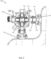
- Fig. 5 shows the connector assembly of this disclosure used to connect two ports 301, 302 of a valve 300 to two respective ports 401, 402 of a tank, where the ports are at about 90 degrees from each other.
- the connector assembly can be advantageous in other connections and arrangements.
- the use of the moving sleeve ensures that such a valve assembly or other structure can be properly mounted to other parts of a fluid flow system.
- the sleeve allows for some movement of the engaging parts and builds some tolerance into the connection.
- the sleeve is simple and no special tools are required for its use and assembly and allows the use of a known clamp for securement of the connection.
Landscapes
- Engineering & Computer Science (AREA)
- General Engineering & Computer Science (AREA)
- Mechanical Engineering (AREA)
- Quick-Acting Or Multi-Walled Pipe Joints (AREA)
- Valve Housings (AREA)
Priority Applications (3)
| Application Number | Priority Date | Filing Date | Title |
|---|---|---|---|
| EP21461553.6A EP4105534A1 (de) | 2021-06-15 | 2021-06-15 | Verbinderbaugruppe |
| CA3158545A CA3158545A1 (en) | 2021-06-15 | 2022-05-05 | Connector assembly |
| US17/826,721 US20220397217A1 (en) | 2021-06-15 | 2022-05-27 | Connector assembly |
Applications Claiming Priority (1)
| Application Number | Priority Date | Filing Date | Title |
|---|---|---|---|
| EP21461553.6A EP4105534A1 (de) | 2021-06-15 | 2021-06-15 | Verbinderbaugruppe |
Publications (1)
| Publication Number | Publication Date |
|---|---|
| EP4105534A1 true EP4105534A1 (de) | 2022-12-21 |
Family
ID=76483258
Family Applications (1)
| Application Number | Title | Priority Date | Filing Date |
|---|---|---|---|
| EP21461553.6A Pending EP4105534A1 (de) | 2021-06-15 | 2021-06-15 | Verbinderbaugruppe |
Country Status (3)
| Country | Link |
|---|---|
| US (1) | US20220397217A1 (de) |
| EP (1) | EP4105534A1 (de) |
| CA (1) | CA3158545A1 (de) |
Citations (6)
| Publication number | Priority date | Publication date | Assignee | Title |
|---|---|---|---|---|
| US3438657A (en) * | 1967-01-25 | 1969-04-15 | Purolator Products Inc | Swaged ferrule type flexible coupling |
| US3776579A (en) * | 1971-03-11 | 1973-12-04 | Stanley Aviation Corp | Coupling assemblies |
| EP0485885A1 (de) * | 1990-11-13 | 1992-05-20 | A. und K. Müller GmbH & Co. KG | Ausgabeventilanordnung für Brühwasser, insbesondere an einem Heissgetränkeautomaten, sowie Betriebsverfahren zur Steuerung der Ausgabeventilanordnung |
| US9599262B1 (en) * | 2016-12-06 | 2017-03-21 | Robin C. Moore | Sleeve tool and method of use |
| US20170343141A1 (en) * | 2016-05-27 | 2017-11-30 | John O. Roper | Rotatable Pipe Adapter |
| EP3714745A1 (de) * | 2019-03-05 | 2020-09-30 | Be Aerospace, Inc. | Verteileranordnung mit integrierten entlüftungs- und durchflussregelungsanschlüssen |
Family Cites Families (3)
| Publication number | Priority date | Publication date | Assignee | Title |
|---|---|---|---|---|
| US2781207A (en) * | 1953-01-12 | 1957-02-12 | Lockheed Aircraft Corp | Flexible couplings for beaded tubing |
| US20130207383A1 (en) * | 2009-12-15 | 2013-08-15 | Georg Fischer Llc | Containment Pipe Fittings and Methods |
| JP6392716B2 (ja) * | 2015-08-31 | 2018-09-19 | Ckd株式会社 | 配管接続構造 |
-
2021
- 2021-06-15 EP EP21461553.6A patent/EP4105534A1/de active Pending
-
2022
- 2022-05-05 CA CA3158545A patent/CA3158545A1/en active Pending
- 2022-05-27 US US17/826,721 patent/US20220397217A1/en active Pending
Patent Citations (6)
| Publication number | Priority date | Publication date | Assignee | Title |
|---|---|---|---|---|
| US3438657A (en) * | 1967-01-25 | 1969-04-15 | Purolator Products Inc | Swaged ferrule type flexible coupling |
| US3776579A (en) * | 1971-03-11 | 1973-12-04 | Stanley Aviation Corp | Coupling assemblies |
| EP0485885A1 (de) * | 1990-11-13 | 1992-05-20 | A. und K. Müller GmbH & Co. KG | Ausgabeventilanordnung für Brühwasser, insbesondere an einem Heissgetränkeautomaten, sowie Betriebsverfahren zur Steuerung der Ausgabeventilanordnung |
| US20170343141A1 (en) * | 2016-05-27 | 2017-11-30 | John O. Roper | Rotatable Pipe Adapter |
| US9599262B1 (en) * | 2016-12-06 | 2017-03-21 | Robin C. Moore | Sleeve tool and method of use |
| EP3714745A1 (de) * | 2019-03-05 | 2020-09-30 | Be Aerospace, Inc. | Verteileranordnung mit integrierten entlüftungs- und durchflussregelungsanschlüssen |
Also Published As
| Publication number | Publication date |
|---|---|
| US20220397217A1 (en) | 2022-12-15 |
| CA3158545A1 (en) | 2022-12-15 |
Similar Documents
| Publication | Publication Date | Title |
|---|---|---|
| AU2011306630B2 (en) | Tubular joint | |
| US7159616B2 (en) | Dual path hydraulic coupling | |
| US4159132A (en) | Sealed connection | |
| US6123363A (en) | Self-centering low profile connection with trapped gasket | |
| US20110163540A1 (en) | O-ringless seal couplings | |
| JPH01500453A (ja) | 外側にねじを設けた迅速連結継ぎ手 | |
| JP3711365B2 (ja) | コンポーネント対コンポーネントのシール方法 | |
| RU2402713C2 (ru) | Соединительный узел для трубопроводов | |
| JPH0762514B2 (ja) | 急速ストレート連結流体用カツプラ | |
| EP4105534A1 (de) | Verbinderbaugruppe | |
| KR200391276Y1 (ko) | 관이음 구조 | |
| CN116194696A (zh) | 具有形成在止回阀壳体、止回阀主体转换部和锁定换之间的止回阀组件接头的止回阀组件 | |
| US5863078A (en) | Pipe coupling | |
| AU2004257931B8 (en) | A hydraulic coupling device and a valve device provided with a sealing member | |
| US8888144B2 (en) | Misalignment connector utilizing interleaved bearings | |
| US11857933B2 (en) | Systems, apparatuses, and methods for mixing fluids using a conical flow member | |
| SK8633Y1 (sk) | Spojovací mechanizmus | |
| KR20050014783A (ko) | 튜브 및 필터하우징사이의 연결장치 | |
| KR970028015A (ko) | 유체 및 가스 시스템을 위한 편평한 하부 구성 요소 및 편평한 하부 구조를 이용한 밸브 및 장치 | |
| US11841085B1 (en) | Piston actuated cartridge valve | |
| JPS5928798B2 (ja) | 自動調心流体用継手 | |
| EP4040030B1 (de) | Fluidflussverbinder | |
| US20080048437A1 (en) | Method and apparatus for end-to-end coupling of component bores | |
| CN107289129A (zh) | 一种液压系统通道体径向密封装置 | |
| TR2024002011A2 (tr) | Mi̇sket valf ti̇pli̇, yüksek sicaklikli akişkanlara uygun emni̇yetli̇ ki̇li̇tlenebi̇len hizli bağlanti elemani |
Legal Events
| Date | Code | Title | Description |
|---|---|---|---|
| PUAI | Public reference made under article 153(3) epc to a published international application that has entered the european phase |
Free format text: ORIGINAL CODE: 0009012 |
|
| STAA | Information on the status of an ep patent application or granted ep patent |
Free format text: STATUS: THE APPLICATION HAS BEEN PUBLISHED |
|
| AK | Designated contracting states |
Kind code of ref document: A1 Designated state(s): AL AT BE BG CH CY CZ DE DK EE ES FI FR GB GR HR HU IE IS IT LI LT LU LV MC MK MT NL NO PL PT RO RS SE SI SK SM TR |
|
| STAA | Information on the status of an ep patent application or granted ep patent |
Free format text: STATUS: REQUEST FOR EXAMINATION WAS MADE |
|
| 17P | Request for examination filed |
Effective date: 20230621 |
|
| RBV | Designated contracting states (corrected) |
Designated state(s): AL AT BE BG CH CY CZ DE DK EE ES FI FR GB GR HR HU IE IS IT LI LT LU LV MC MK MT NL NO PL PT RO RS SE SI SK SM TR |
|
| P01 | Opt-out of the competence of the unified patent court (upc) registered |
Effective date: 20230922 |