EP4103855B1 - Längsverstellbare zug-druck-stange mit widerstandsmomentvorrichtung - Google Patents
Längsverstellbare zug-druck-stange mit widerstandsmomentvorrichtung Download PDFInfo
- Publication number
- EP4103855B1 EP4103855B1 EP20716178.7A EP20716178A EP4103855B1 EP 4103855 B1 EP4103855 B1 EP 4103855B1 EP 20716178 A EP20716178 A EP 20716178A EP 4103855 B1 EP4103855 B1 EP 4103855B1
- Authority
- EP
- European Patent Office
- Prior art keywords
- connecting rod
- fork
- rod
- shank
- toothing
- Prior art date
- Legal status (The legal status is an assumption and is not a legal conclusion. Google has not performed a legal analysis and makes no representation as to the accuracy of the status listed.)
- Active
Links
- 238000003825 pressing Methods 0.000 claims description 30
- 238000004519 manufacturing process Methods 0.000 claims description 11
- 238000002347 injection Methods 0.000 claims description 9
- 239000007924 injection Substances 0.000 claims description 9
- 239000011324 bead Substances 0.000 claims description 8
- 229920001169 thermoplastic Polymers 0.000 claims description 8
- 239000004416 thermosoftening plastic Substances 0.000 claims description 8
- 239000007769 metal material Substances 0.000 claims description 7
- 230000000295 complement effect Effects 0.000 claims description 5
- 238000000034 method Methods 0.000 claims description 4
- 230000008569 process Effects 0.000 claims description 3
- 238000001746 injection moulding Methods 0.000 claims 2
- 208000031968 Cadaver Diseases 0.000 description 8
- 230000008901 benefit Effects 0.000 description 6
- 230000000694 effects Effects 0.000 description 4
- 229910052782 aluminium Inorganic materials 0.000 description 3
- XAGFODPZIPBFFR-UHFFFAOYSA-N aluminium Chemical compound [Al] XAGFODPZIPBFFR-UHFFFAOYSA-N 0.000 description 3
- 230000008859 change Effects 0.000 description 3
- 238000007906 compression Methods 0.000 description 3
- 229910052751 metal Inorganic materials 0.000 description 3
- 239000002184 metal Substances 0.000 description 3
- 230000000903 blocking effect Effects 0.000 description 2
- 239000002131 composite material Substances 0.000 description 2
- 230000006835 compression Effects 0.000 description 2
- 230000007797 corrosion Effects 0.000 description 2
- 238000005260 corrosion Methods 0.000 description 2
- 230000008878 coupling Effects 0.000 description 2
- 238000010168 coupling process Methods 0.000 description 2
- 238000005859 coupling reaction Methods 0.000 description 2
- 230000003247 decreasing effect Effects 0.000 description 2
- 230000003100 immobilizing effect Effects 0.000 description 2
- 238000009434 installation Methods 0.000 description 2
- 239000000463 material Substances 0.000 description 2
- 229920001187 thermosetting polymer Polymers 0.000 description 2
- OKTJSMMVPCPJKN-UHFFFAOYSA-N Carbon Chemical compound [C] OKTJSMMVPCPJKN-UHFFFAOYSA-N 0.000 description 1
- RTAQQCXQSZGOHL-UHFFFAOYSA-N Titanium Chemical compound [Ti] RTAQQCXQSZGOHL-UHFFFAOYSA-N 0.000 description 1
- 208000027418 Wounds and injury Diseases 0.000 description 1
- 238000004026 adhesive bonding Methods 0.000 description 1
- 239000000956 alloy Substances 0.000 description 1
- 229910045601 alloy Inorganic materials 0.000 description 1
- 229910052799 carbon Inorganic materials 0.000 description 1
- 238000006243 chemical reaction Methods 0.000 description 1
- 230000006378 damage Effects 0.000 description 1
- 230000007423 decrease Effects 0.000 description 1
- 208000014674 injury Diseases 0.000 description 1
- 230000007246 mechanism Effects 0.000 description 1
- 238000012986 modification Methods 0.000 description 1
- 230000004048 modification Effects 0.000 description 1
- 229920000642 polymer Polymers 0.000 description 1
- 238000007789 sealing Methods 0.000 description 1
- 239000000243 solution Substances 0.000 description 1
- 239000010936 titanium Substances 0.000 description 1
- 229910052719 titanium Inorganic materials 0.000 description 1
Images


Classifications
-
- F—MECHANICAL ENGINEERING; LIGHTING; HEATING; WEAPONS; BLASTING
- F16—ENGINEERING ELEMENTS AND UNITS; GENERAL MEASURES FOR PRODUCING AND MAINTAINING EFFECTIVE FUNCTIONING OF MACHINES OR INSTALLATIONS; THERMAL INSULATION IN GENERAL
- F16C—SHAFTS; FLEXIBLE SHAFTS; ELEMENTS OR CRANKSHAFT MECHANISMS; ROTARY BODIES OTHER THAN GEARING ELEMENTS; BEARINGS
- F16C7/00—Connecting-rods or like links pivoted at both ends; Construction of connecting-rod heads
- F16C7/06—Adjustable connecting-rods
-
- F—MECHANICAL ENGINEERING; LIGHTING; HEATING; WEAPONS; BLASTING
- F16—ENGINEERING ELEMENTS AND UNITS; GENERAL MEASURES FOR PRODUCING AND MAINTAINING EFFECTIVE FUNCTIONING OF MACHINES OR INSTALLATIONS; THERMAL INSULATION IN GENERAL
- F16C—SHAFTS; FLEXIBLE SHAFTS; ELEMENTS OR CRANKSHAFT MECHANISMS; ROTARY BODIES OTHER THAN GEARING ELEMENTS; BEARINGS
- F16C2226/00—Joining parts; Fastening; Assembling or mounting parts
- F16C2226/50—Positive connections
- F16C2226/60—Positive connections with threaded parts, e.g. bolt and nut connections
-
- F—MECHANICAL ENGINEERING; LIGHTING; HEATING; WEAPONS; BLASTING
- F16—ENGINEERING ELEMENTS AND UNITS; GENERAL MEASURES FOR PRODUCING AND MAINTAINING EFFECTIVE FUNCTIONING OF MACHINES OR INSTALLATIONS; THERMAL INSULATION IN GENERAL
- F16C—SHAFTS; FLEXIBLE SHAFTS; ELEMENTS OR CRANKSHAFT MECHANISMS; ROTARY BODIES OTHER THAN GEARING ELEMENTS; BEARINGS
- F16C2226/00—Joining parts; Fastening; Assembling or mounting parts
- F16C2226/50—Positive connections
- F16C2226/70—Positive connections with complementary interlocking parts
- F16C2226/74—Positive connections with complementary interlocking parts with snap-fit, e.g. by clips
-
- F—MECHANICAL ENGINEERING; LIGHTING; HEATING; WEAPONS; BLASTING
- F16—ENGINEERING ELEMENTS AND UNITS; GENERAL MEASURES FOR PRODUCING AND MAINTAINING EFFECTIVE FUNCTIONING OF MACHINES OR INSTALLATIONS; THERMAL INSULATION IN GENERAL
- F16C—SHAFTS; FLEXIBLE SHAFTS; ELEMENTS OR CRANKSHAFT MECHANISMS; ROTARY BODIES OTHER THAN GEARING ELEMENTS; BEARINGS
- F16C2226/00—Joining parts; Fastening; Assembling or mounting parts
- F16C2226/50—Positive connections
- F16C2226/70—Positive connections with complementary interlocking parts
- F16C2226/76—Positive connections with complementary interlocking parts with tongue and groove or key and slot
-
- Y—GENERAL TAGGING OF NEW TECHNOLOGICAL DEVELOPMENTS; GENERAL TAGGING OF CROSS-SECTIONAL TECHNOLOGIES SPANNING OVER SEVERAL SECTIONS OF THE IPC; TECHNICAL SUBJECTS COVERED BY FORMER USPC CROSS-REFERENCE ART COLLECTIONS [XRACs] AND DIGESTS
- Y10—TECHNICAL SUBJECTS COVERED BY FORMER USPC
- Y10T—TECHNICAL SUBJECTS COVERED BY FORMER US CLASSIFICATION
- Y10T74/00—Machine element or mechanism
- Y10T74/21—Elements
- Y10T74/2142—Pitmans and connecting rods
- Y10T74/2151—Longitudinally adjustable
Definitions
- the present invention relates to the technical field of connecting rods, shafts and arms intended to be positioned between two fixed or mobile members whose length can be adjustable in order to adjust and relates in particular to a connecting rod adjustable in length provided with a torque device resistant.
- Connecting rods of this type are used for example between a fixed member and a movable member such as a shutter mechanism. Due to the manufacturing and assembly tolerances of the different components, the distance between the two can fluctuate according to these tolerances by several millimeters. To be able to put the connecting rod in place, you must be able to adjust its length. This is possible thanks to length-adjustable connecting rods comprising a connecting element such as for example a fork, a ball joint or a metal yoke and a tube which cooperates thanks to a threaded device in order to change the length of the connecting rod when it is set up.
- a connecting element such as for example a fork, a ball joint or a metal yoke
- a tube which cooperates thanks to a threaded device in order to change the length of the connecting rod when it is set up.
- the length-adjustable connecting rod may also include a rotational braking device which acts on the rotational movement in order to apply a determined locking force between the fork and the tube and thus prevent an untimely change in length of the connecting rod when it is not required to voluntarily vary its length, as in the case of stresses due to vibrations, fatigue cycle in traction, compression, flexion, thermal gradient up to 140°C.
- the document WO2006042750 describes a traction-compression bar which comprises a fork and a tube, the rotation of the fork around the tube can be locked using a blocking device which comprises a partial ring provided with a locking nose and a toothed crown.
- the disadvantage of such a device is that it requires an intermediate part such as a sleeve placed between the fork and the tube and comprising two threads, a first thread located on the external wall of the sleeve making it possible to connect the tube of the connecting rod and a second thread located on the internal wall allowing the fork to be connected.
- the first thread When assembling the connecting rod, the first thread must be kept blocked because only the second thread is involved in adjusting the length of the connecting rod. This double thread complicates the manufacturing and assembly of the parts that make up the connecting rod.
- we want to secure the blocking of the first thread we must carry out an additional step consisting, for example, of gluing the thread.
- the connecting rod locking device described in the document WO2006042750 acts on the tightening torque between the fork and the tube thanks to the locking nose of the partial ring which is housed in a space in the toothed crown.
- the partial ring is connected to the fork thanks to an offset bolt and a connection element which connects the partial ring to the bolt.
- the fact that the partial ring is fixed on the connecting rod thanks to a fixing element offset relative to the plane in which the tightening force is exerted creates a tightening torque between the fork and the tube which varies according to the position of the fork in the tube.
- the locking nose of the partial ring is not aligned, according to the direction of the axis of rotation, on the connection element, which means that the tightening torque is not identical depending on whether the The operator turns the connecting rod in one direction or the other. Consequently, the tightening torque between the fork and the tube also varies depending on the direction of adjustment of the fork relative to the tube.
- the connecting rod described in the document WO2011057627 includes two threads, one of which allows you to modify the length of the connecting rod.
- This thread comprises a first thread located on the outside of the fork which cooperates with a second thread located inside a connecting part.
- a spring presses two locking elements against each other in the longitudinal direction of the connecting rod.
- the spring being supported with its ends between the fork and the connecting piece, it also presses the outer thread against the inner thread of the thread which allows the length of the connecting rod to be changed.
- One of the disadvantages of this connecting rod lies in the fact that the tightening torque depends on the friction between the locking elements but also depends on the friction between the two threads.
- the aim of the invention is to produce a connecting rod adjustable in length provided with a resistant torque device which overcomes the aforementioned drawbacks and in particular which comprises a single thread per end and provides a constant resistant torque and this , whatever the position of the fork relative to the tube.
- Another aim of the invention is to propose a simple and economical manufacturing process making it possible to produce length-adjustable connecting rods whose resistant torque device provides a constant resistant torque whatever the position of the fork relative to the tube.
- the object of the invention is therefore a connecting rod adjustable in length having a longitudinal axis, comprising a connecting rod body provided with at least one internal thread, at least one junction element comprising an external thread cooperating with the internal thread of the body connecting rod, screwing or unscrewing the connecting rod body relative to the junction element making it possible to adjust the length of the connecting rod and at least one resistant torque device between the connecting rod body and the junction element, the connecting device resistant torque comprising at least one pressing element and a support element, the pressing element exerting a force on the support element which opposes resistance to the rotational movement of the connecting rod body relative to said junction element.
- the connecting rod is characterized in that the support element is integral with the junction element and the pressing element is integral with the connecting rod body and in that the force exerted by the pressing element on the element d
- the support is done in a transverse direction and perpendicular to the longitudinal axis of the connecting rod.
- the connecting rod 1 has a rectilinear shape and comprises an elongated and hollow body 50 whose center is shown in dotted lines in the figure.
- the connecting rod is equipped on at least one of its ends with a junction element 10 comprising on its free end junction means 11 and 13 which serve to connect the connecting rod to its location.
- the connecting rod 1 comprises a second junction element 20 identical to the first junction element 10 and two opposite threads.
- the junction element 20 comprises on its free end junction means 21 and 23.
- the junction element 10 and 20 is a fork. However, it could be a yoke or a ball joint without departing from the scope of the invention.
- the fork 10 comprises two ends 11 each provided with an orifice 13 and the fork 20 comprises two ends 21 each provided with an orifice 23.
- the connecting rod 1 is equipped with at least one identical resistant torque device 30 and/or 40 between each fork and the connecting rod body.
- Each resistant torque device comprises an element presser and a support element.
- the pressing element is produced according to different embodiments described later in the description.
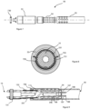
- FIG 2 illustrates an entire fork 10 or 20 as well as the part of the resistant torque device integral with the fork which corresponds to the support element of the resistant torque device.
- the fork 10 or 20 has a longitudinal central axis represented by the axis 5.
- the fork 10 or 20 and the support element are rotated by 90° around the axis 5 relative to the figure 2 .
- the support element of the resistant torque device integral with the fork is represented as part of a separate element 300 of the fork, added during assembly of the connecting rod, however it could be machined directly on the metal fork, for example in aluminum, without departing from the scope of the invention.
- the embodiment described and illustrated by the figures is therefore the preferred embodiment when the support device and the fork are not made from the same material, for example for an aluminum fork and a thermoplastic support element. .
- This embodiment makes it possible to reduce the risk of galvanic corrosion.
- the support element is mounted integrally on the junction element using means for immobilizing it on the junction element. These means are described in the remainder of the description.
- the free end of the fork 10 is extended by a central cylindrical part 101 which supports the support element of the resistant torque device.
- the central cylindrical part 101 is provided with a collar 102 located on the external face of the cylindrical part 101 on the side of the free end of the fork.
- the collar is circular and located in a plane perpendicular to axis 5 and its external diameter is greater than the external diameter of the cylindrical part by 0.1 mm to 0.5 mm.
- the collar has two opposite faces, a flat face perpendicular to axis 5 and a frustoconical shaped face.
- the flat face is located on the side of the free end of the fork while the frustoconical face is directed in the opposite direction, therefore towards the center of the connecting rod.
- the cylindrical part is extended by a groove 105 adapted to accommodate a seal sealing 115, a thread 106 and two blades 107 each provided on their external face and at their end with a stopping element in the form of a bead 108 projecting radially outwards.
- the central cylindrical part 101 comprises at least one slot 103 located on its external surface and parallel to the axis 5 extending from the groove 105 towards the middle part of the cylindrical part.
- the central cylindrical part 101 comprises a second slot also located on its external surface, parallel and preferably diametrically opposite to the first slot.
- the seal 115 guarantees the seal between the tube and the fork against galvanic corrosion.
- the support element of the resistant torque device and integral with the fork is a set of teeth 331 comprising a set of teeth. Even in the case where the support element is machined directly with the fork, the teeth 331 are preferably straight, that is to say that the teeth of the teeth 331 are distributed uniformly circumferentially and parallel to the longitudinal axis 5.
- the toothing 331 is part of a toothed ring 300.
- the toothed ring has a cylindrical shape and has on its external surface a smooth part 332 and the toothing 331.
- the fork 10 and 20 and the notched ring 300 include means for immobilizing the notched ring on the fork.
- the interior of the ring 300 is not shown in the figures and includes an annular groove formed at the edge of the cylindrical internal face of the ring on the side of its smooth part.
- the internal diameter of the notched ring is equal to or slightly greater than the external diameter of the cylindrical part 101 of the fork on which it is positioned.
- the notched ring is put in place by threading onto the fork through its second end located on the opposite side of its free end up to the collar 102 so that its internal face is in surface support on the external face of the cylindrical part 101 of the fork.
- the complementary shape of the collar 102 and the annular groove of the ring allows the sliding of the notched ring over the collar by exerting sufficient force so that it is inserted into the groove, the groove of the ring notched and the collar 102 thus cooperating together.
- the flat, perpendicular face of the collar prevents the ring from being removed by sliding in the direction opposite to its installation.
- the teeth 331 are located on the external face of the cylindrical part 101.
- the notched ring 300 also includes at least one rectilinear boss formed on its internal face. This rectilinear boss extends from the edge of the ring on the side of the smooth part to its middle part and is parallel to the longitudinal axis 5. The shape of this boss is complementary with the slot 103 of the cylindrical part 101 so as to that the boss of the notched ring 300 and the slot 103 cooperate together when the ring is slipped on the fork 10 or 20.
- the ring comprises a second diametrically opposite boss on its internal surface so that each boss cooperates with each of the two slots in the fork.
- the connecting rod 1 comprises at least one fixing element adapted to connect the two ends 11 of the fork 10 in a direction transverse to the longitudinal axis of the connecting rod.
- the fixing element is a latching clip 130 comprising a pin 131 passing through the two openings 13 or the two openings 23 of the ends 11 or the ends 21 of the fork 10 or 20 via two rings 133.
- the pin 131 is connected to a clip 132 which snaps elastically around the central cylindrical part 101 of the fork, on the smooth part 332 of the notched ring or directly on the fork in the case where the support element is machined directly on the fork.
- the locking clip 130 allows the connecting rod to be coupled and locked to an external body without preventing its length from being adjusted.
- FIG. 4 illustrates one of the two ends of the connecting rod body 50 in exploded view. It is composed of a tip 53 of cylindrical shape, a threaded insert 54 of cylindrical shape and a tube 55.
- the threaded insert is assembled and fixed to the tube thanks to the end piece made partly around the threaded insert, between the threaded insert and the tube and around the tube by a thermoplastic injection process or thermoplastic over-injection on a metal part such as described in the patent application EP 3 302 916 .
- the end piece is made of thermoplastic or thermoplastic composite and the tube is made from a thermoplastic or thermosetting composite, for example thermosetting carbon.
- the threaded insert can be made of polymer such as a thermoplastic but also of metallic material or a combination of the two.
- the metallic material may be aluminum or titanium or an alloy of the two.
- the fork is made at both ends of a hollow tubular structure, for weight reasons.
- the pressing element of the resistant torque device 30, integral with the connecting rod body 50, is intended to cooperate with the support element of the resistant torque device and therefore with the teeth 331.
- the pressing element of the resistant torque device 30 comprises at least one ball pusher 530 and the means for fixing the pressing element is a housing 533 per ball pusher 530, each housing 533 being provided in the thickness of the walls of the connecting rod body and more precisely in the thickness of the wall of the end piece 53 on the side opposite the tube 55.
- FIG. 5 represents a cross section of the connecting rod perpendicular to axis 5 comprising two ball pushers 530 according to a preferred embodiment.
- Ball plungers are ball and spring loaded.
- a spring 532 compresses a ball 531 mounted freely in the ball pusher and part of the surface of which is flush with the outside of the pusher.
- the ball pusher has on its external face on the ball side a collar which abuts against a shoulder of the housing 533 when it is inserted into it through an opening on the internal face of the wall of the end piece 53.
- the shape of the housing 533 of the ball pusher 530 is adapted to immobilize the pusher against any translational movement in both directions of the longitudinal axis 5 of the connecting rod.
- THE housing 533 is therefore preferably cylindrical with a diameter equal to or slightly greater than the diameter of the part of the ball pusher without the collar.
- each ball pusher 530 When the fork 10 and the connecting rod body 50 are assembled together, the flush surface of the ball 531 of each ball pusher 530 is in permanent contact with the teeth 331 of the resistant torque device. The ball pushers can no longer be removed from their housing because they are stuck between end piece 53 and teeth 331.
- each ball cooperates with a hollow of the teeth 331.
- the dimension of the balls is adapted to cooperate with a hollow of the teeth 331 and the shape of the hollows of the teeth 331 is complementary with the shape of the balls.
- the ball pushers are integral with the end piece 53 and therefore with the connecting rod body. The rotation of the connecting rod body causes the ball pushers 530 to rotate. The spring of each ball pusher exerts a force on the ball and therefore on the teeth 331 which increases during the passage of the ball from a hollow between two teeth to adjacent hollow.
- Each ball pusher provides a point, independent and equal spring effect on the teeth, exerted by the spring which pushes on the ball and acts only in the direction of the axis of the pusher in order to push the ball into a hollow in the teeth.
- the force exerted by each ball on the teeth 331 is then identical and predictable, which has the advantage of being able to dimension the desired force by increasing or decreasing the number of ball pushers.
- the number of pushers can be between 1 and 8.
- THE figures 6a, 6b and 6c illustrate a longitudinal section of one end of the connecting rod equipped with the fork 10 in three positions of the fork 10 relative to the connecting rod body 50.
- the fork is inserted into the connecting rod body by the end piece 53 until that the external thread 106 of the fork cooperates with a thread 546 located on the internal face of the insert 54.
- the fork is then screwed until the end 108 of the blades 107 projecting radially from the fork 10 exceed the end of the insert 54, the blades 107 provided with the bead 108 at their ends then serve as means of stopping the fork in the connecting rod body by preventing it from being removed during a unscrewing the fork.
- the maximum size of the connecting rod is reached when the shoulder of the bead 108 of the end of the blades 107 abuts against the end of the insert 54.
- the connecting rod body 50 comprises two threaded inserts 54 each provided with a thread 546 and two end pieces 53.
- the threading device of the second fork is oriented in the opposite direction to the threading device of the first fork so that the rotation in one direction of the connecting rod body causes the two forks to exit and the rotation of the connecting rod body in the opposite direction causes the two forks to enter the connecting rod body.
- figure 6c represents the position of the connecting rod when the fork 10 is retracted to the maximum and the figure 6a represents an intermediate position of the fork.
- the fork can move by rotating in the connecting rod body 50 between two positions without being able to be removed from the connecting rod body thanks to the stopping means 107 and 108 provided to block the fork in the connecting rod body and which are automatically active during the assembly of the connecting rod.
- the pressing element of the resistant coupling device secured to the connecting rod body comprises at least one leaf spring 730 and the end piece 53 comprises at least one means for fixing the pressing element.
- the fixing means is at least one housing 733 per leaf spring 730, each housing 733 being provided inside the end piece 53 on the side opposite the tube 55.
- the 730 spring blade is seen in detail on the Figure 7 which represents a cross section of the connecting rod perpendicular to axis 5.
- the leaf spring 730 partly surrounds the teeth 331.
- At least one of the two ends of the leaf spring 730 is inserted into a housing 733 in the form of a notch provided on the internal surface in the thickness of the walls of the connecting rod body and more precisely in the thickness of the walls of the end piece 53.
- the shape of the housing of at least one end of the blade spring is adapted to immobilize the blade spring against any translational movement in both directions of the longitudinal axis 5.
- the positioning of the blade spring in its housing of the end piece 53 makes the blade secured to the end piece 53 and therefore secured to the connecting rod body 50.
- the spring blade can no longer be removed from its location because it is stuck between the end piece 53 and the teeth 331 of the resistant torque device.
- the blade 730 is stuck but not completely immobilized so that there is a space between the tip 53 and the teeth 331 for the spring blade to exert its elasticity.
- the blade 730 comprises at least one tooth 731 whose shape is adapted to cooperate with a hollow of the teeth 331.
- the device according to the invention comprises more than one leaf spring, each leaf spring has a single tooth 731 and all the leaf springs are identical.
- the leaf springs are then positioned side by side in the end piece so that the teeth 731 are uniformly distributed angularly.
- This has the advantage of centering the fork in the connecting rod body.
- Each blade has at least one end inserted in a notch 733 provided in the wall of the end piece 53.
- Each spring blade has a point, independent and equal spring effect on the teeth exerted by the blade which pushes the tooth 731 into a hollow of teeth 331.
- each tooth 731 on the notched ring 300 and therefore on the teeth 331 is then identical and predictable, which has the advantage of being able to dimension the desired force by increasing or decreasing the number of blades as for ball pushers .
- the blades are positioned so as to be symmetrical with respect to a plane passing through the longitudinal axis 5 of the connecting rod.
- the two teeth are therefore diametrically opposed and if only one end of each blade is inserted into a housing of the tip, these are either the two ends located closest to the teeth, or the two ends furthest from the teeth.
- the leaf spring has two teeth 731, and these are diametrically opposed as can be seen in the figure 5 .
- the rotation of the connecting rod body and therefore of the end piece 53 causes the blade spring 730 to rotate.
- the spring effect of each blade exerts a force on the tooth 731 and therefore on the teeth 331 which increases during the passage of the tooth 731 from a hollow between two teeth of the toothing 331 to the adjacent hollow.
- This effort opposes a resistance to the rotational movement of the connecting rod body relative to the fork by friction of the tooth 731 against the teeth which means that the operator must exert a necessary and sufficient torque force to rotate the connecting rod body by relation to the fork.
- This necessary and sufficient torque must be greater than the resistant torque of tooth 731 on teeth 331.
- FIG. 9 illustrates a longitudinal section of one end of the connecting rod according to the second embodiment when the fork is in an intermediate position between the position where it is extended to the maximum with reference to the figure 6b and the position where it is retracted to the maximum with reference to the figure 6c .
- the pressing elements when no rotational torque is exerted on the connecting rod, the pressing elements exert a force radial on the support element perpendicular to the longitudinal axis 5 of the connecting rod.
- the pressing element exerts a radial force and a tangential force on the support element, the two forces being located in a transverse plane and perpendicular to the longitudinal axis 5 of the connecting rod.
- the connecting rod according to the invention provides a resistant torque with preferably a value defined between 0.5Nm and 10Nm and preferably between 1Nm and 3 Nm.
- the torque resistor ensures the set length of the connecting rod by maintaining a minimum torque resistant to misadjustment once the connecting rod has been installed and adjusted in length, even when installed on structures subject to vibration.
- the resistant torque of the connecting rod according to the invention can be increased by increasing the number of ball pushers or leaf springs, the connecting rod according to the invention can be adapted to more stressed structures without requiring many modifications in its manufacturing process .
- a plurality of housings for ball pushers or spring blades can be provided in the manufacture of the end piece and be provided as necessary with the required number of pushers or blades to obtain a connecting rod with the desired resistant torque.
- the torque exerted to set the connecting rod body in rotational movement applies in the same transverse plane as the resistant torque exerted by the resistant torque device of the connecting rod according to the invention.
- the housing 533 and 733 of each pressing element and the pressing element have a common plane of symmetry perpendicular to the longitudinal axis 5 of the connecting rod.
- the force exerted by the pressing element is also contained in this plane.
- the means of fixing the pressing element on the tip is not offset along the longitudinal axis relative to the axis of the force it exerts.
- the method of manufacturing the connecting rod is such that once the connecting rod is assembled it is no longer possible to separate the fork from the connecting rod body, the means for stopping the fork in the connecting rod body being put into place automatically.
- the assembled connecting rod is a one-piece device. Consequently, the two elements of the resistant coupling device (including the support element secured to the fork and including the pressing element secured to the connecting rod body) can no longer be disengaged from one another.
- the connecting rod cannot change length without the resistive torque device being actuated.
- the connecting rod according to the invention has the advantage of having a resistant torque device that is active all the time and cannot be dismantled. Even in the event of incorrect assembly of the locking clip by the operator, the resistant torque is guaranteed by the connecting rod according to the invention, which is essential in the case of use on an aircraft. Indeed, the detent clip having the sole unique function of connecting the connecting rod to the intended location of its installation, it does not apply any effort additional on the rotational movement of the connecting rod body relative to the fork.
- the connecting rod according to the invention reduces the risk of injury for the operator who handles and installs the connecting rod.
Landscapes
- Engineering & Computer Science (AREA)
- General Engineering & Computer Science (AREA)
- Mechanical Engineering (AREA)
- Mutual Connection Of Rods And Tubes (AREA)
Claims (14)
- Längenverstellbare Pleuelstange mit einer Längsachse (5), umfassend einen Pleuelkörper (50), der mit mindestens einem Innengewinde (546) ausgestattet ist, mindestens ein Verbindungselement (10, 20) mit einem Außengewinde (106), das mit dem Innengewinde des Pleuelkörpers zusammenwirkt, wobei das Ein- oder Ausschrauben des Pleuelkörpers in Bezug auf das Verbindungselement die Verstellung der Länge der Pleuelstange ermöglicht, und mindestens eine Widerstandsdrehmomentvorrichtung (30, 40) zwischen dem Pleuelkörper und dem Verbindungselement, wobei die Widerstandsdrehmomentvorrichtung mindestens ein Druckelement (530, 730) und ein Abstützelement umfasst, wobei das Druckelement eine Kraft auf das Abstützelement ausübt, die der Rotationsbewegung des Pleuelkörpers in Bezug auf das Verbindungselement einen Widerstand entgegensetzt,wobei das Abstützelement eine Verzahnung (331) ist, die eine Gruppe von Zähnen umfasst, die mit dem Verbindungselement (10, 20) fest verbunden ist, und das Druckelement (530, 730) mit dem Pleuelkörper (50) fest verbunden ist, so dass die vom Druckelement (530, 730) auf die Verzahnung (331) ausgeübte Kraft in einer Querrichtung und senkrecht zur Längsachse der Pleuelstange (50) erfolgt,und so dass das Verbindungselement (10, 20) ein freies Ende umfasst, das mit Verbindungsmitteln (11, 13) oder (21, 23) versehen ist, das sich in einen zentralen zylindrischen Teil (101) verlängert, der die Verzahnung (331) und eine Nut (105) trägt, die dazu angepasst ist, eine Dichtung (115) darin aufzunehmen.
- Pleuelstange nach Anspruch 1, wobei der Pleuelkörper (50) mindestens ein Befestigungsmittel (533, 733) für das Druckelement (530, 730) umfasst, wobei das Befestigungsmittel für das Druckelement und das Druckelement eine gemeinsame Symmetrieebene senkrecht zur Längsachse (5) der Pleuelstange haben.
- Pleuelstange nach Anspruch 1 oder 2, wobei das Verbindungselement (10, 20) durch Drehen im Pleuelkörper (50) zwischen zwei Positionen bewegt werden kann, ohne aus dem Pleuelkörper herausgezogen werden zu können, wobei Rastmittel (107, 108) vorgesehen sind, um das Verbindungselement in dem Pleuelkörper zu arretieren, wobei die Rastmittel beim Zusammenbau der Pleuelstange automatisch aktiv sind.
- Pleuelstange nach einem der Ansprüche 1 bis 3, wobei die Verzahnung (331) Teil eines gezahnten Rings (300) ist, wobei das Verbindungselement (10, 20) und der Ring Mittel zum Fixieren des gezahnten Rings am Verbindungselement (10, 20) umfassen.
- Pleuelstange nach Anspruch 4, wobei der zentrale zylindrische Teil (101) auf seiner Außenfläche auf der Seite des freien Endes des Verbindungselements einen Kragen (102), der kreisförmig ist und sich in einer Ebene senkrecht zur Längsachse (5) befindet, und mindestens einen Schlitz (103) parallel zur Achse (5) aufweist, wobei der Außendurchmesser des Kragens um 0,1 mm bis 0,5 mm größer ist als der Außendurchmesser des zylindrischen Teils (101), wobei der Kragen zwei gegenüberliegende Flächen aufweist, eine ebene Fläche senkrecht zur Achse (5), die sich auf der Seite des freien Endes des Verbindungselements befindet, und eine kegelstumpfförmige Fläche, die zu dem Zentrum der Pleuelstange hin gerichtet ist.
- Pleuelstange nach Anspruch 5, wobei der Innendurchmesser des zylinderförmigen gezahnten Rings gleich oder etwas größer ist als der Außendurchmesser des zylindrischen Teils (101 ) des Verbindungselements, der gezahnte Ring auf seiner zylindrischen Innenfläche eine ringförmige Rille mit einer Form komplementär zu der des Kragens (102) und mindestens einen geradlinigen Vorsprung mit einer Form komplementär zu der des Schlitzes (103) aufweist, so dass, wenn der gezahnte Ring (300) auf das Verbindungselement (10, 20) aufgezogen ist, die Rille des gezahnten Rings mit dem Kragen (102) zusammenwirkt und der Vorsprung des gezahnten Rings (300) mit dem Schlitz (103) zusammenwirkt, um den gezahnten Ring (300) auf dem Verbindungselement (10, 20) zu fixieren.
- Pleuelstange nach einem der Ansprüche 1 bis 6, wobei der hohle Pleuelkörper (50) aus einem Endstück (53), einem Gewindeeinsatz (54), der das Gewinde (546) auf seiner Innenfläche umfasst, und einem Rohr (55) besteht, wobei der Gewindeeinsatz an dem Rohr durch das Endstück befestigt ist, das teilweise um den Gewindeeinsatz, zwischen dem Gewindeeinsatz und dem Rohr und um das Rohr herum durch ein Thermoplast-Spritzgussverfahren gefertigt wird.
- Pleuelstange nach einem der Ansprüche 2 bis 7, wobei das Druckelement mindestens einen Kugelstößel (530) oder mindestens ein Federblatt (730) umfasst, wobei das Mittel zur Befestigung des Druckelements eine Aufnahme (533) pro Kugelstößel (530) oder mindestens eine Aufnahme (733) pro Blattfeder (730) ist, die in der Dicke der Wand des Pleuelkörpers (50) vorgesehen ist, wobei die Form der Aufnahme (533, 733) so angepasst ist, dass sie den Stößel oder das Blatt gegen eine Translationsbewegung in beiden Richtungen der Längsachse (5) der Pleuelstange fixiert.
- Pleuelstange nach Anspruch 8, wobei im Falle mehrerer Kugelstößel (530) oder Federblätter (730) diese unabhängig voneinander sind und über den Umfang des Pleuelkörpers (50) winkelmäßig gleichmäßig verteilt sind.
- Pleuelstange nach Anspruch 8 oder 9, wobei der Kugelstößel (530) eine Feder (532) umfasst, die eine Kugel (531) zusammendrückt, die frei in dem Stößel montiert ist, wobei ein Teil der Oberfläche der Kugel, der mit der Außenseite des Stößels bündig ist, in ständigem Kontakt mit der Verzahnung (331) der Widerstandsdrehmomentvorrichtung steht, wenn das Verbindungselement (10, 20) auf dem Pleuelkörper (50) zusammengebaut ist, wobei die Kugel eine Größe hat, die dazu angepasst ist, mit einer Aushöhlung der Verzahnung (331) zusammenzuwirken.
- Pleuelstange nach Anspruch 8 oder 9, wobei das Federblatt (730) die Verzahnung (331) teilweise umgibt und mindestens eines seiner Enden in eine Aufnahme (733) eingesetzt ist, wobei das Blatt mindestens einen Zahn (731) aufweist, dessen Form dazu angepasst ist, mit einer Vertiefung der Verzahnung (331) zusammenzuwirken, wobei der Zahn (731) in ständigem Kontakt mit der Verzahnung (331) der Widerstandsdrehmomentvorrichtung steht, wenn das Verbindungselement (10, 20) auf dem Pleuelkörper (50) zusammengebaut ist.
- Pleuelstange nach einem der Ansprüche 1 bis 11, wobei das Verbindungselement (10) oder (20) eine Gabel ist, wobei die Verbindungsmittel der Gabel (10) zwei Enden (11) sind, die jeweils mit einer Öffnung (13) versehen sind, und die Verbindungsmittel der Gabel (20) zwei Enden (21) sind, die jeweils mit einer Öffnung (23) versehen sind, wobei die Pleuelstange mindestens ein Befestigungselement in Form eines Einrastclips (130) mit einem Stift (131) umfasst, der dazu bestimmt ist, die beiden Öffnungen (13) oder (23) der Gabel (10) oder (20) über zwei Ringe (133) zu durchqueren, wobei der Stift mit einem Clip (132) verbunden ist, der elastisch um den zylindrischen zentralen Teil der Gabel (10, 20) einrastet, um die Pleuelstange an ein äußeres Organ anzukoppeln, ohne die Einstellung ihrer Länge zu verhindern.
- Verfahren zur Herstellung und zum Zusammenbau einer Pleuelstange nach einem der Ansprüche 1 bis 12 in Kombination mit den Ansprüchen 4, 7 und 8, das die folgenden Schritte umfasst:a) der Pleuelkörper (50), der aus dem Endstück (53), dem Gewindeeinsatz (54) und dem Rohr (55) besteht, wird in einem einzigen Spritzgussschritt hergestellt und zusammengebaut,b) das Verbindungselement (10, 20) ist vorzugsweise aus einem metallischen Material einstückig bearbeitet, mit einem ersten freien Ende und einem zweiten Ende, das eine Rastvorrichtung (107, 108) aufweist,c) der gezahnte Ring (300) ist fest an dem Verbindungselement montiert,d) die Dichtung (115) ist in der Nut (105) angeordnet, die an dem Verbindungselement am Ende des gezahnten Rings vorgesehen ist,e) mindestens ein Kugelstößel (530) oder ein Federblatt (730) ist in der dafür vorgesehenen Aufnahme in der Dicke der Wand des Endstücks angeordnet,f) das Verbindungselement wird durch Zusammenwirken der Gewinde in den Pleuelkörper eingesetzt und eingeschraubt und bis die beiden Blätter (107), die sich am entgegengesetzten Ende des freien Endes des Verbindungselements befinden, mit ihrem Rastelement in Form eines radial nach außen vorstehenden Wulstes (108) gegen das Ende des Gewindeeinsatzes anstoßen, wodurch die Anschlageinrichtung automatisch in Position gebracht wird.
- Verfahren zur Herstellung und zum Zusammenbau einer Pleuelstange nach einem der Ansprüche 1 bis 12 in Kombination mit den Ansprüchen 4, 7 und 8, das die folgenden Schritte umfasst:a) der Pleuelkörper (50), der aus dem Endstück (53), dem Gewindeeinsatz (54) und dem Rohr (55) besteht, wird in einem einzigen Spritzgussschritt hergestellt und zusammengebaut,b) das Verbindungselement (10, 20) ist vorzugsweise aus einem metallischen Material einstückig bearbeitet, mit einem ersten freien Ende und einem zweiten Ende, das eine Rastvorrichtung (107, 108) aufweist, und einem zylindrischen zentralen Teil, der die Verzahnung (331) umfasst,c) die Dichtung (115) ist in der Nut (105) angeordnet, die an dem Verbindungselement vorgesehen ist,d) mindestens ein Kugelstößel (530) oder ein Federblatt (730) ist in der dafür vorgesehenen Aufnahme in der Dicke der Wand des Endstücks angeordnet,e) das Verbindungselement wird durch Zusammenwirken der Gewinde in den Pleuelkörper eingesetzt und eingeschraubt und bis die beiden Blätter (107), die sich am entgegengesetzten Ende des freien Endes des Verbindungselements befinden, mit ihrem Rastelement in Form eines radial nach außen vorstehenden Wulstes (108) gegen das Ende des Gewindeeinsatzes anstoßen, wodurch die Rastvorrichtung automatisch in Position gebracht wird.
Applications Claiming Priority (1)
| Application Number | Priority Date | Filing Date | Title |
|---|---|---|---|
| PCT/FR2020/000032 WO2021160941A1 (fr) | 2020-02-14 | 2020-02-14 | Bielle ajustable en longueur munie d'un dispositif de couple résistant |
Publications (2)
| Publication Number | Publication Date |
|---|---|
| EP4103855A1 EP4103855A1 (de) | 2022-12-21 |
| EP4103855B1 true EP4103855B1 (de) | 2024-04-03 |
Family
ID=70110271
Family Applications (1)
| Application Number | Title | Priority Date | Filing Date |
|---|---|---|---|
| EP20716178.7A Active EP4103855B1 (de) | 2020-02-14 | 2020-02-14 | Längsverstellbare zug-druck-stange mit widerstandsmomentvorrichtung |
Country Status (3)
| Country | Link |
|---|---|
| US (1) | US20230080669A1 (de) |
| EP (1) | EP4103855B1 (de) |
| WO (1) | WO2021160941A1 (de) |
Family Cites Families (10)
| Publication number | Priority date | Publication date | Assignee | Title |
|---|---|---|---|---|
| CH324803A (de) * | 1953-09-21 | 1957-10-15 | Schuler L Ag | Mehrteilige Pleuelstange |
| US5702196A (en) * | 1996-06-21 | 1997-12-30 | Teleflex, Incorporated | Turnbuckle-type adjustable link |
| JP2005030477A (ja) * | 2003-07-10 | 2005-02-03 | Koyo Seiko Co Ltd | 伸縮自在シャフト |
| DE202004004407U1 (de) * | 2004-03-18 | 2004-07-22 | Trigum-Engineering Gmbh | Zug-Druck-Stange |
| DE202004016321U1 (de) * | 2004-10-20 | 2005-03-10 | Trigum-Engineering Gmbh | Zug-Druck-Stange |
| US20120224913A1 (en) * | 2009-11-10 | 2012-09-06 | Ro-Ra Produktions Gmbh | Push/pull rod |
| DE202011002079U1 (de) * | 2011-01-28 | 2011-05-12 | Gmt Gummi-Metall-Technik Gmbh | Sicherungsklipp mit Verriegelung |
| EP2844885A1 (de) * | 2012-05-02 | 2015-03-11 | Jet Aviation AG | Ankerstabkopf |
| DE202012103224U1 (de) * | 2012-08-26 | 2012-09-14 | Ro-Ra Produktions Gmbh | Zug-Druck-Stange |
| FR3036643A1 (fr) | 2015-06-01 | 2016-12-02 | Epsilon Composite | Embout surmoule |
-
2020
- 2020-02-14 EP EP20716178.7A patent/EP4103855B1/de active Active
- 2020-02-14 US US17/796,243 patent/US20230080669A1/en not_active Abandoned
- 2020-02-14 WO PCT/FR2020/000032 patent/WO2021160941A1/fr unknown
Also Published As
| Publication number | Publication date |
|---|---|
| WO2021160941A1 (fr) | 2021-08-19 |
| US20230080669A1 (en) | 2023-03-16 |
| EP4103855A1 (de) | 2022-12-21 |
Similar Documents
| Publication | Publication Date | Title |
|---|---|---|
| EP2689110B1 (de) | Absperrvorrichtung mit automatisch aktivierbarer verriegelung | |
| EP1916182B1 (de) | Fahrrad-Steuerkopflager | |
| FR2771370A1 (fr) | Dispositif de support de moyeu de roue de bicyclette | |
| FR2905152A1 (fr) | Dispositif de fixation avec compensation de tolerances | |
| EP2496849B1 (de) | Selbstblockierende schraubfixiervorrichtung und anordnung damit | |
| WO1994010929A1 (fr) | Dispositif de fixation sur une tige pour orthopedie rachidienne | |
| FR3037115A1 (fr) | Dispositif de poulie pour galet tendeur ou enrouleur | |
| EP0402198B1 (de) | Verriegelungsmutter | |
| FR2976987A1 (fr) | Dispositif de montage pour la fixation rotative et imperdable d'un element mecanique | |
| EP0536005B1 (de) | Vorrichtung zum schnellen Montieren und Demontieren von zwei aufeinanderliegenden Teilen | |
| EP1553310B1 (de) | Vorrichtung zur lösbaren Verriegelung eines Endstückes auf einer Struktur mit verstellbarer Position | |
| EP4103855B1 (de) | Längsverstellbare zug-druck-stange mit widerstandsmomentvorrichtung | |
| EP3299650B1 (de) | Verfahren zum ausstatten eines endes eines dünnwandigen rohres mit einem mittels einer verschraubung einstellbaren axialanschlag | |
| FR2459906A1 (fr) | Butee d'embrayage a auto-centrage | |
| WO2004083657A9 (fr) | Dispositif de fixation a pince | |
| EP0699280A1 (de) | Schwimmsattel scheibenbremse | |
| EP0268510B1 (de) | Vorrichtung zur Blindbefestigung von mindestens zwei Teilen, zum Beispiel Bleche | |
| EP0079291B1 (de) | Sicherheitsmutterpaar mit doppelter Sicherung | |
| EP1092880A1 (de) | Schraubmechanismusbefestigungsvorrichtung mit Spielausgleichsvorrichtung zwischen zwei Bauteilen | |
| EP2818744A1 (de) | Verschlusssystem für Laufring | |
| FR2607201A1 (fr) | Dispositif de fixation sur fut filete ou annele | |
| EP0207833B1 (de) | Gewindezapfen mit Drehmomentbegrenzung | |
| EP0307327A1 (de) | Schraubverbindungensvorrichtung für zwei Elemente mit der Möglichkeit den Abstand dazwischen einzustellen | |
| FR3058389B1 (fr) | Dispositif de montage d'un axe sur une chape | |
| FR3084272A1 (fr) | Dispositif pour la tenue d'une tige comprenant un troncon filete |
Legal Events
| Date | Code | Title | Description |
|---|---|---|---|
| STAA | Information on the status of an ep patent application or granted ep patent |
Free format text: STATUS: UNKNOWN |
|
| STAA | Information on the status of an ep patent application or granted ep patent |
Free format text: STATUS: THE INTERNATIONAL PUBLICATION HAS BEEN MADE |
|
| PUAI | Public reference made under article 153(3) epc to a published international application that has entered the european phase |
Free format text: ORIGINAL CODE: 0009012 |
|
| STAA | Information on the status of an ep patent application or granted ep patent |
Free format text: STATUS: REQUEST FOR EXAMINATION WAS MADE |
|
| 17P | Request for examination filed |
Effective date: 20220804 |
|
| AK | Designated contracting states |
Kind code of ref document: A1 Designated state(s): AL AT BE BG CH CY CZ DE DK EE ES FI FR GB GR HR HU IE IS IT LI LT LU LV MC MK MT NL NO PL PT RO RS SE SI SK SM TR |
|
| DAV | Request for validation of the european patent (deleted) | ||
| DAX | Request for extension of the european patent (deleted) | ||
| GRAP | Despatch of communication of intention to grant a patent |
Free format text: ORIGINAL CODE: EPIDOSNIGR1 |
|
| STAA | Information on the status of an ep patent application or granted ep patent |
Free format text: STATUS: GRANT OF PATENT IS INTENDED |
|
| INTG | Intention to grant announced |
Effective date: 20231102 |
|
| GRAS | Grant fee paid |
Free format text: ORIGINAL CODE: EPIDOSNIGR3 |
|
| GRAA | (expected) grant |
Free format text: ORIGINAL CODE: 0009210 |
|
| STAA | Information on the status of an ep patent application or granted ep patent |
Free format text: STATUS: THE PATENT HAS BEEN GRANTED |
|
| AK | Designated contracting states |
Kind code of ref document: B1 Designated state(s): AL AT BE BG CH CY CZ DE DK EE ES FI FR GB GR HR HU IE IS IT LI LT LU LV MC MK MT NL NO PL PT RO RS SE SI SK SM TR |
|
| REG | Reference to a national code |
Ref country code: CH Ref legal event code: EP |
|
| REG | Reference to a national code |
Ref country code: DE Ref legal event code: R096 Ref document number: 602020028314 Country of ref document: DE |