EP4102684A1 - Stator für eine elektrische maschine, elektrische maschine, kraftfahrzeug - Google Patents
Stator für eine elektrische maschine, elektrische maschine, kraftfahrzeug Download PDFInfo
- Publication number
- EP4102684A1 EP4102684A1 EP22020057.0A EP22020057A EP4102684A1 EP 4102684 A1 EP4102684 A1 EP 4102684A1 EP 22020057 A EP22020057 A EP 22020057A EP 4102684 A1 EP4102684 A1 EP 4102684A1
- Authority
- EP
- European Patent Office
- Prior art keywords
- stator
- electrical conductors
- slots
- slot insulation
- core
- Prior art date
- Legal status (The legal status is an assumption and is not a legal conclusion. Google has not performed a legal analysis and makes no representation as to the accuracy of the status listed.)
- Granted
Links
Images

Classifications
-
- H—ELECTRICITY
- H02—GENERATION; CONVERSION OR DISTRIBUTION OF ELECTRIC POWER
- H02K—DYNAMO-ELECTRIC MACHINES
- H02K1/00—Details of the magnetic circuit
- H02K1/06—Details of the magnetic circuit characterised by the shape, form or construction
- H02K1/12—Stationary parts of the magnetic circuit
- H02K1/16—Stator cores with slots for windings
-
- H—ELECTRICITY
- H02—GENERATION; CONVERSION OR DISTRIBUTION OF ELECTRIC POWER
- H02K—DYNAMO-ELECTRIC MACHINES
- H02K3/00—Details of windings
- H02K3/32—Windings characterised by the shape, form or construction of the insulation
- H02K3/34—Windings characterised by the shape, form or construction of the insulation between conductors or between conductor and core, e.g. slot insulation
- H02K3/345—Windings characterised by the shape, form or construction of the insulation between conductors or between conductor and core, e.g. slot insulation between conductor and core, e.g. slot insulation
-
- H—ELECTRICITY
- H02—GENERATION; CONVERSION OR DISTRIBUTION OF ELECTRIC POWER
- H02K—DYNAMO-ELECTRIC MACHINES
- H02K1/00—Details of the magnetic circuit
- H02K1/06—Details of the magnetic circuit characterised by the shape, form or construction
- H02K1/12—Stationary parts of the magnetic circuit
- H02K1/16—Stator cores with slots for windings
- H02K1/165—Shape, form or location of the slots
-
- H—ELECTRICITY
- H02—GENERATION; CONVERSION OR DISTRIBUTION OF ELECTRIC POWER
- H02K—DYNAMO-ELECTRIC MACHINES
- H02K1/00—Details of the magnetic circuit
- H02K1/06—Details of the magnetic circuit characterised by the shape, form or construction
- H02K1/12—Stationary parts of the magnetic circuit
- H02K1/20—Stationary parts of the magnetic circuit with channels or ducts for flow of cooling medium
-
- H—ELECTRICITY
- H02—GENERATION; CONVERSION OR DISTRIBUTION OF ELECTRIC POWER
- H02K—DYNAMO-ELECTRIC MACHINES
- H02K15/00—Processes or apparatus specially adapted for manufacturing, assembling, maintaining or repairing of dynamo-electric machines
- H02K15/02—Processes or apparatus specially adapted for manufacturing, assembling, maintaining or repairing of dynamo-electric machines of stator or rotor bodies
- H02K15/021—Magnetic cores
-
- H—ELECTRICITY
- H02—GENERATION; CONVERSION OR DISTRIBUTION OF ELECTRIC POWER
- H02K—DYNAMO-ELECTRIC MACHINES
- H02K15/00—Processes or apparatus specially adapted for manufacturing, assembling, maintaining or repairing of dynamo-electric machines
- H02K15/13—Applying slot closure means in the cores; Manufacture of slot closure means
-
- H—ELECTRICITY
- H02—GENERATION; CONVERSION OR DISTRIBUTION OF ELECTRIC POWER
- H02K—DYNAMO-ELECTRIC MACHINES
- H02K21/00—Synchronous motors having permanent magnets; Synchronous generators having permanent magnets
- H02K21/12—Synchronous motors having permanent magnets; Synchronous generators having permanent magnets with stationary armatures and rotating magnets
- H02K21/14—Synchronous motors having permanent magnets; Synchronous generators having permanent magnets with stationary armatures and rotating magnets with magnets rotating within the armatures
-
- H—ELECTRICITY
- H02—GENERATION; CONVERSION OR DISTRIBUTION OF ELECTRIC POWER
- H02K—DYNAMO-ELECTRIC MACHINES
- H02K3/00—Details of windings
- H02K3/04—Windings characterised by the conductor shape, form or construction, e.g. with bar conductors
- H02K3/24—Windings characterised by the conductor shape, form or construction, e.g. with bar conductors with channels or ducts for cooling medium between the conductors
-
- H—ELECTRICITY
- H02—GENERATION; CONVERSION OR DISTRIBUTION OF ELECTRIC POWER
- H02K—DYNAMO-ELECTRIC MACHINES
- H02K3/00—Details of windings
- H02K3/46—Fastening of windings on the stator or rotor structure
- H02K3/48—Fastening of windings on the stator or rotor structure in slots
-
- H—ELECTRICITY
- H02—GENERATION; CONVERSION OR DISTRIBUTION OF ELECTRIC POWER
- H02K—DYNAMO-ELECTRIC MACHINES
- H02K9/00—Arrangements for cooling or ventilating
- H02K9/19—Arrangements for cooling or ventilating for machines with closed casing and closed-circuit cooling using a liquid cooling medium, e.g. oil
-
- H—ELECTRICITY
- H02—GENERATION; CONVERSION OR DISTRIBUTION OF ELECTRIC POWER
- H02K—DYNAMO-ELECTRIC MACHINES
- H02K9/00—Arrangements for cooling or ventilating
- H02K9/19—Arrangements for cooling or ventilating for machines with closed casing and closed-circuit cooling using a liquid cooling medium, e.g. oil
- H02K9/193—Arrangements for cooling or ventilating for machines with closed casing and closed-circuit cooling using a liquid cooling medium, e.g. oil with provision for replenishing the cooling medium; with means for preventing leakage of the cooling medium
-
- H—ELECTRICITY
- H02—GENERATION; CONVERSION OR DISTRIBUTION OF ELECTRIC POWER
- H02K—DYNAMO-ELECTRIC MACHINES
- H02K9/00—Arrangements for cooling or ventilating
- H02K9/19—Arrangements for cooling or ventilating for machines with closed casing and closed-circuit cooling using a liquid cooling medium, e.g. oil
- H02K9/197—Arrangements for cooling or ventilating for machines with closed casing and closed-circuit cooling using a liquid cooling medium, e.g. oil in which the rotor or stator space is fluid-tight, e.g. to provide for different cooling media for rotor and stator
-
- B—PERFORMING OPERATIONS; TRANSPORTING
- B60—VEHICLES IN GENERAL
- B60K—ARRANGEMENT OR MOUNTING OF PROPULSION UNITS OR OF TRANSMISSIONS IN VEHICLES; ARRANGEMENT OR MOUNTING OF PLURAL DIVERSE PRIME-MOVERS IN VEHICLES; AUXILIARY DRIVES FOR VEHICLES; INSTRUMENTATION OR DASHBOARDS FOR VEHICLES; ARRANGEMENTS IN CONNECTION WITH COOLING, AIR INTAKE, GAS EXHAUST OR FUEL SUPPLY OF PROPULSION UNITS IN VEHICLES
- B60K1/00—Arrangement or mounting of electrical propulsion units
- B60K2001/003—Arrangement or mounting of electrical propulsion units with means for cooling the electrical propulsion units
- B60K2001/006—Arrangement or mounting of electrical propulsion units with means for cooling the electrical propulsion units the electric motors
-
- B—PERFORMING OPERATIONS; TRANSPORTING
- B60—VEHICLES IN GENERAL
- B60Y—INDEXING SCHEME RELATING TO ASPECTS CROSS-CUTTING VEHICLE TECHNOLOGY
- B60Y2200/00—Type of vehicle
- B60Y2200/90—Vehicles comprising electric prime movers
- B60Y2200/91—Electric vehicles
-
- B—PERFORMING OPERATIONS; TRANSPORTING
- B60—VEHICLES IN GENERAL
- B60Y—INDEXING SCHEME RELATING TO ASPECTS CROSS-CUTTING VEHICLE TECHNOLOGY
- B60Y2400/00—Special features of vehicle units
- B60Y2400/60—Electric Machines, e.g. motors or generators
Definitions
- the present invention relates to a stator for an electrical machine, having a stator lamination stack, the stator lamination stack having stator slots arranged along an axial direction parallel to a stator axis, electrical conductors being arranged in the stator slots, wherein between the electrical conductors and the stator lamination stack in the stator slots fluid-tight slot insulation are arranged. Furthermore, the present invention relates to an electrical machine with a stator and a motor vehicle with an electrical machine.
- the coolant is usually introduced into a winding overhang area of the stator.
- the cooling liquid continues to flow along the electrical conductors through the stator slots of the stator into another winding overhang area. There, the coolant can exit the stator and the heat absorbed by the coolant can be dissipated.
- a stator for an electrical machine having a laminated stator core, the laminated stator core having stator slots arranged in an axial direction parallel to a stator axis, electrical conductors being arranged in the stator slots, wherein between the electrical conductors and the laminated stator core in the Stator slots fluid-tight slot insulation are arranged, the slot insulation each having a spaced-apart in a direction orthogonal to the axial direction radial direction to the electrical conductors cooling channel.
- the stator according to the invention enables the use of smaller pumps, which are significantly lighter and cheaper.
- the flow resistance is noticeably reduced by the cooling ducts, at the same time the efficiency of the cooling of the electrical conductors is hardly impaired and in particular the efficiency of the cooling of the winding overhangs is not impaired at all. Furthermore, the lower flow resistance leads to a significantly longer service life of the pumps.
- the electrical conductors are conductor rails with, in particular, a rectangular cross section.
- the electrical conductors are particularly preferably hairpin elements.
- stator core stamped. It is also conceivable, however, for the laminated core of the stator to be packaged by means of welding, preferably laser welding, along the back of the stator, or by applying a baked lacquer.
- stator is a stator of an internal rotor.
- the cooling ducts are arranged in slot slots of the laminated core of the stator.
- the cooling channels are provided as bulges of the slot insulation in the slot slots.
- the cooling channels do not protrude beyond the electrical conductors in the circumferential direction of the laminated core of the stator.
- the cooling ducts are arranged in a recess on the yoke side of the laminated core of the stator. This advantageously results in very good cooling on the yoke side of the electrical lines. It is preferably provided that the recesses and the cooling channels do not protrude beyond the electrical conductors in the direction of rotation of the laminated stator core, but preferably have a smaller extent than the electrical conductors in the direction of rotation.
- the electrical conductors are arranged in interior spaces of the slot insulation, with the cooling channels being fluidically connected to the interior spaces are. This makes it possible in an advantageous manner for the cooling liquid to flow both through the cooling ducts and through the interior spaces, and with low flow resistance the electrical conductors are directly acted upon by the cooling liquid and are thus cooled.
- the electrical conductors are arranged in interior spaces of the slot insulation, with the cooling channels being separated from the interior spaces in a fluidically sealed manner.
- the electrical conductors are cooled indirectly.
- the fluidic separation of the cooling channels from the interior spaces enables a very stable structure of the slot insulation.
- the stator has an end disk on one end face of the stator lamination stack, the end disk having a radial part, a main direction of extension of the radial part being arranged in the radial direction, the radial part having openings for passage which has electrical lines through the radial part from the stator slots into an end winding area of the stator and further openings for fluidly connecting the cooling channels to the end winding area.
- the end winding space is sealed off from the stator lamination stack, which can prevent coolant from getting from the end winding area into the air gap of the electrical machine between the rotor and stator, where it leads to severe friction losses.
- the front disk is fastened to the front side in a fluid-tight manner, so that no coolant can get between the front disk and the front side.
- the end plate itself is fluid-tight.
- the end plate is made of an electrically insulating material. It is conceivable that the front disk is made of a plastic, preferably a fiber-reinforced plastic.
- the openings have fluid-tight seals between the winding overhang space and the interior spaces of the cooling channels. This ensures in an advantageous manner that, in particular in the case of indirect cooling of the electrical conductors in the stator slots, no cooling liquid from the winding overhang area gets into the interior.
- edges of the openings are connected to edges of the slot insulation in a fluid-tight manner, with the edges of the openings preferably being welded to the edges of the slot insulation, glued or injection-molded onto the edges of the slot insulation. In this way, it is ensured in an advantageous manner that no cooling liquid gets at the openings between the end disk and the end face and from there into the air gap.
- edges of the further openings are preferably connected in a fluid-tight manner to edges of the slot insulation, in particular to edges of the cooling channels, with the edges of the openings preferably being welded to the edges of the slot insulation, glued or injection-molded onto the edges of the slot insulation.
- the end plate has an axial part, with a main extension direction of the axial part being arranged in the axial direction, with the axial part having channels, the channels being arranged along a main extension direction of the cooling channels.
- stator and/or preferably the electrical machine has a can, the can having channels, the channels being arranged along a main extension direction of the cooling channels.
- the end disk in particular the radial part, is glued to the end face of the laminated stator core or is injection-molded onto the end face of the laminated stator core. This advantageously brings about a very good seal to prevent coolant from escaping from the end winding space into an area between the end disk and the end face.
- a further object of the present invention for solving the problem formulated at the outset is an electrical machine having a stator according to the invention.
- a further object of the present invention for solving the problem formulated at the outset is a motor vehicle having an electric machine according to the invention.
- stator according to the invention also relate to the electric machine according to the invention and to the motor vehicle according to the invention.
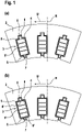
- Fig. 1 (a) and (b) each schematically illustrate a detail of a stator 1 according to an exemplary embodiment of the present invention.
- FIG.1(a) a part of the stator 1 is shown.
- a laminated stator core 2 with three stator slots 3 can be seen.
- Electrical conductors 4 preferably parts of a hairpin winding, are arranged in the stator slots 3 .
- the slot insulation 5 is fluid-tight. This makes it possible for a cooling liquid, for example an oil, to flow through the slot insulation 5 and directly act on and cool the electrical conductors 4 arranged in the inner spaces 5 ′ of the slot insulation 5 .
- the fluid-tightness of the slot insulation 5 effectively prevents the cooling liquid from escaping through slot slots 7 into an area between the stator 1 and a rotor (see Fig. 3 ), the so-called air gap, and leads to strong friction losses there.
- cooling channels 6 spaced apart from the electrical conductors 4 are provided in the radial direction R.
- the lower flow resistance means that smaller, lighter and cheaper pumps can be used to generate the coolant flow.
- cooling channels 6 are provided in recesses 8 of the stator core 2 on the yoke side and in the slots 7 . This brings about a uniform cooling of the electrical conductors 4 .
- cooling channels 6 have less expansion in the circumferential direction U than the electrical conductors 4.
- Fig.1(b) shows a part of a stator 1 according to a further preferred embodiment of the present invention.
- the stator like that in Fig.1(a) shown, also arranged in the stator 3 electrical conductors 4 on.
- the slot insulations 5 are arranged around the electrical conductors 4 with the cooling channels 6 spaced apart from the electrical conductors in the radial direction R in the slot slots 7 and the recesses 8 of the stator core 2 on the yoke side.
- the embodiment shown here differs from that in Fig.1(a) in that partition walls 6' are arranged between the cooling channels 6 and the inner spaces 5' of the slot insulation 5, in which the electrical conductors 4 are arranged.
- the partition walls 6 ′ are fluid-tight and prevent cooling liquid from reaching the interior spaces 5 from the cooling channels 6 .
- FIG. 1 schematically illustrates a detail of a stator 1 according to an exemplary embodiment of the present invention in a perspective view.
- An electrically insulating and fluid-tight end disk 9 arranged on an end face 2' of the stator core 2 can be seen.
- the end disk 9 has a radial part 9.1 which is connected in a fluid-tight manner to the end face 2'.
- the radial part 9.1 has openings 9.3 for passing the electrical conductors 4 out of the stator slots (see Fig. Fig.1(a),(b) ) in a winding head area 10. Furthermore, the radial part 9.1 has further openings 9.4, through which the cooling channels 6 are connected to the end winding area 10.
- the edges of the openings 9.3 and the edges of the other openings 9.4 are connected to the slot insulation 5 in a fluid-tight manner.
- stator 2 has seals 9.7 in the area of the openings 9.3, which prevent coolant from penetrating from the end winding area 10 into the interior (see Fig. Fig.1(a),(b) ) impede.
- the front disk 9 also has an axial part 9.5 which extends in the axial direction A.
- the axial part 9.5 prevents cooling liquid from getting from the end winding area 10 into a rotor space (not shown) and thus into the air gap.
- the axial part 9.5 has channels 9.6, which extend in the axial direction A in front of the cooling channels 6, which are located in the slots (see Fig. Fig.1(a),(b) ) are arranged.
- FIG. 3 1 schematically illustrates a motor vehicle 200 according to an exemplary embodiment of the present invention with an electric machine 100 according to an exemplary embodiment of the present invention.
- the electric machine 100 has a rotor 11 and a stator according to an exemplary embodiment of the present invention.
Landscapes
- Engineering & Computer Science (AREA)
- Power Engineering (AREA)
- Manufacturing & Machinery (AREA)
- Motor Or Generator Cooling System (AREA)
- Iron Core Of Rotating Electric Machines (AREA)
- Windings For Motors And Generators (AREA)
Abstract
Description
- Die vorliegende Erfindung betrifft einen Stator für eine elektrische Maschine, aufweisend ein Statorblechpaket, wobei das Statorblechpaket entlang einer zu einer Statorachse parallelen axialen Richtung angeordnete Statornuten aufweist, wobei in den Statornuten elektrische Leiter angeordnet sind, wobei zwischen den elektrischen Leitern und dem Statorblechpaket in den Statornuten fluiddichte Nutisolationen angeordnet sind. Weiterhin betrifft die vorliegende Erfindung eine elektrische Maschine mit einem Stator sowie ein Kraftfahrzeug mit einer elektrischen Maschine.
- Elektrische Maschinen, insbesondere hochperformante elektrische Maschinen, müssen im Betrieb gekühlt werden. Typischerweise ist die Temperaturverträglichkeit von Komponenten der elektrischen Maschine leistungslimitierend, wodurch der Kühlung besondere Aufmerksamkeit zukommt.
- Als besonders effektiv hat sich erwiesen, die elektrischen Leiter des Stators einer elektrischen Maschine direkt mit einer Kühlflüssigkeit, beispielsweise mit einem Öl, zu beaufschlagen. Hierzu wird die Kühlflüssigkeit üblicherweise in einen Wickelkopfbereich des Stators eingeleitet. Die Kühlflüssigkeit strömt weiter entlang der elektrischen Leiter durch Statornuten des Stators bis in einen weiteren Wickelkopfbereich. Dort kann die Kühlflüssigkeit aus dem Stator austreten und die von der Kühlflüssigkeit aufgenommene Wärme abgeführt werden.
- Das beschriebene Verfahren aus dem Stand der Technik ist zwar sehr effizient, allerdings bewirkt die Passage der Kühlflüssigkeit durch die Statornuten entlang der elektrischen Leitungen einen hohen Strömungswiderstand, was entsprechend starke Pumpen zur Erzeugung des Kühlflüssigkeitsstromes erfordert und zu hohen Kosten, einem hohen Gewicht und einem großen benötigten Bauraum der Pumpen führt.
- Es ist daher eine Aufgabe der vorliegenden Erfindung, einen Stator für eine elektrische Maschine zur Verfügung zu stellen, welcher die genannten Nachteile des Standes der Technik nicht aufweist, sondern die Verwendung von kleineren und damit leichteren und günstigeren Pumpen zur Erzeugung des Kühlflüssigkeitsstromes erlaubt.
- Diese Aufgabe wird gelöst durch einen Stator für eine elektrische Maschine, aufweisend ein Statorblechpaket, wobei das Statorblechpaket entlang einer zu einer Statorachse parallelen axialen Richtung angeordnete Statornuten aufweist, wobei in den Statornuten elektrische Leiter angeordnet sind, wobei zwischen den elektrischen Leitern und dem Statorblechpaket in den Statornuten fluiddichte Nutisolationen angeordnet sind, wobei die Nutisolationen jeweils einen in einer zur axialen Richtung orthogonal angeordneten radialen Richtung zu den elektrischen Leitern beabstandeten Kühlkanal aufweisen.
- Der erfindungsgemäße Stator ermöglicht die Verwendung kleinerer Pumpen, welche deutlich leichter und günstiger sind. Durch die Kühlkanäle wird der Strömungswiderstand merklich gesenkt, gleichzeitig die Effizienz der Kühlung der elektrischen Leiter kaum und insbesondere die Effizienz der Kühlung der Wickelköpfe gar nicht beeinträchtigt. Ferner führt der geringere Strömungswiderstand zu einer deutlich verlängerten Lebensdauer der Pumpen.
- Vorzugsweise ist vorgesehen, dass die elektrischen Leiter Leiterschienen mit insbesondere rechteckigem Querschnitt sind. Besonders bevorzugt sind die elektrischen Leiter Hairpin-Elemente.
- Vorzugsweise ist vorgesehen, dass die Nutisolationen aus PEEK hergestellt sind. Denkbar ist, dass die Nutisolationen in die Statornuten eingeschoben sind. Denkbar ist aber auch, dass die Nutisolationen in die Statornuten laminiert oder gespritzt sind.
- Die Verwendung von Nutisolationen macht es möglich, dass das Statorblechpaket stanzpaketiert ist. Denkbar ist aber auch, dass das Statorblechpaket mittels Schweißen, bevorzugt Laserschweißen, entlang des Statorrückens oder mittels des Auftragens eines Backlacks paketiert ist.
- Vorzugsweise ist vorgesehen, dass der Stator ein Stator eines Innenläufers ist.
- Vorteilhafte Ausgestaltungen und Weiterbildungen der Erfindung sind den Unteransprüchen, sowie der Beschreibung unter Bezugnahme auf die Zeichnungen entnehmbar.
- Gemäß einer bevorzugten Ausführungsform der Erfindung ist vorgesehen, dass die Kühlkanäle in Nutschlitzen des Statorblechpaketes angeordnet sind. Hierdurch ist auf vorteilhafte Weise eine Anordnung der Kühlkanäle mit nur geringen bzw. ohne Beeinträchtigung der elektromagnetischen Eigenschaften des Stators möglich. Denkbar ist, dass die Kühlkanäle als Ausbuchtungen der Nutisolationen in die Nutschlitze vorgesehen sind. Insbesondere ist vorgesehen, dass die Kühlkanäle in Umlaufrichtung des Statorblechpaketes die elektrischen Leiter nicht überragen.
- Gemäß einer weiteren bevorzugten Ausführungsform der Erfindung ist vorgesehen, dass die Kühlkanäle in einer jochseitigen Aussparung des Statorblechpaketes angeordnet sind. Hierdurch ergibt sich auf vorteilhafte Weise eine sehr gute Kühlung an der jochseitigen Seite der elektrischen Leitungen. Vorzugsweise ist vorgesehen, dass die Aussparungen und die Kühlkanäle in Umlaufrichtung des Statorblechpaketes die elektrischen Leiter nicht überragen, sondern vorzugsweise in Umlaufrichtung eine geringere Ausdehnung aufweisen als die elektrischen Leiter.
- Gemäß einer weiteren bevorzugten Ausführungsform der Erfindung ist vorgesehen, dass die elektrischen Leiter in Innenräumen der Nutisolationen angeordnet sind, wobei die Kühlkanäle mit den Innenräumen fluidisch verbunden sind. Hierdurch ist auf vorteilhafte Weise ermöglicht, dass die Kühlflüssigkeit sowohl durch die Kühlkanäle, als auch durch die Innenräume strömt und dabei bei geringem Strömungswiderstand die elektrischen Leiter direkt mit der Kühlflüssigkeit beaufschlagt und somit gekühlt werden.
- Gemäß einer weiteren bevorzugten Ausführungsform der Erfindung ist vorgesehen, dass die elektrischen Leiter in Innenräumen der Nutisolationen angeordnet sind, wobei die Kühlkanäle von den Innenräumen fluidisch dicht getrennt sind. Mit anderen Worten werden die elektrischen Leiter indirekt gekühlt. Durch die fluidische Trennung der Kühlkanäle von den Innenräumen ist eine sehr stabile Struktur der Nutisolationen ermöglicht. Vorzugsweise zur Trennung der Kühlkanäle von den Innenräumen vorgesehene Trennwände versteifen die Nutisolationen, was zu einem deutlich verbesserten Handling bei der Fertigung des Stators führt.
- Gemäß einer weiteren bevorzugten Ausführungsform der Erfindung ist vorgesehen, dass der Stator an einer Stirnseite des Statorblechpaketes eine Stirnscheibe aufweist, wobei die Stirnscheibe einen radialen Teil aufweist, wobei eine Haupterstreckungsrichtung des radialen Teils in der radialen Richtung angeordnet ist, wobei der radiale Teil Öffnungen zum Durchführen der elektrischen Leitungen durch den radialen Teil von den Statornuten in einen Wickelkopfbereich des Stators und weitere Öffnungen zum fluidischen Verbinden der Kühlkanäle mit dem Wickelkopfbereich aufweist. Hierdurch ist ein Abschluss des Wickelkopfraumes zum Statorblechpaket hergestellt, durch welchen verhindert werden kann, dass Kühlflüssigkeit aus dem Wickelkopfbereich in den Luftspalt der elektrischen Maschine zwischen Rotor und Stator gelangt und dort zu starken Reibungsverlusten führt.
- Vorzugsweise ist vorgesehen, dass die Stirnscheibe fluiddicht an der Stirnseite befestigt ist, so dass keine Kühlflüssigkeit zwischen Stirnscheibe und Stirnseite gelangen kann. Hierzu ist vorzugsweise vorgesehen, dass die Stirnscheibe selbst fluiddicht ist.
- Vorzugsweise ist vorgesehen, dass die Stirnscheibe aus einem elektrisch isolierenden Material hergestellt ist. Denkbar ist, dass die Stirnscheibe aus einem Kunststoff, vorzugsweise aus einem faserverstärkten Kunststoff hergestellt ist.
- Gemäß einer weiteren bevorzugten Ausführungsform der Erfindung ist vorgesehen, dass die Öffnungen fluiddichte Abdichtungen zwischen dem Wickelkopfraum und den Innenräumen der Kühlkanäle aufweisen. Hierdurch ist auf vorteilhafte Weise sichergestellt, dass, insbesondere bei indirekter Kühlung der elektrischen Leiter in den Statornuten, keine Kühlflüssigkeit aus dem Wickelkopfbereich in die Innenräume gelangt.
- Gemäß einer weiteren bevorzugten Ausführungsform der Erfindung ist vorgesehen, dass Ränder der Öffnungen mit Rändern der Nutisolationen fluiddicht verbunden sind, wobei die Ränder der Öffnungen bevorzugt mit den Rändern der Nutisolationen verschweißt, verklebt oder an die Ränder der Nutisolationen angespritzt sind. Hierdurch ist auf vorteilhafte Weise sichergestellt, dass keine Kühlflüssigkeit an den Öffnungen zwischen die Stirnscheibe und die Stirnseite und von dort aus in den Luftspalt gelangt.
- Vorzugsweise ist vorgesehen, dass Ränder der weiteren Öffnungen mit Rändern der Nutisolationen, insbesondere mit Rändern der Kühlkanäle, fluiddicht verbunden sind, wobei die Ränder der Öffnungen bevorzugt mit den Rändern der Nutisolationen verschweißt, verklebt oder an die Ränder der Nutisolationen angespritzt sind.
- Gemäß einer weiteren bevorzugten Ausführungsform der Erfindung ist vorgesehen, dass die Stirnscheibe einen axialen Teil aufweist, wobei eine Haupterstreckungsrichtung des axialen Teils in der axialen Richtung angeordnet ist, wobei der axiale Teil Kanäle aufweist, wobei die Kanäle entlang einer Haupterstreckungsrichtung der Kühlkanäle angeordnet sind. Hierdurch ist auf vorteilhafte Weise bewirkt, dass kein zusätzliches Spaltrohr zur Abdichtung des Luftspaltes vorgesehen werden muss. Gleichzeitig bewirken die Kanäle, dass der Strömungswiderstand nicht durch den axialen Teil erhöht wird.
- Denkbar ist aber auch, dass der Stator und/oder vorzugsweise die elektrische Maschine ein Spaltrohr aufweist, wobei das Spaltrohr Kanäle aufweist, wobei die Kanäle entlang einer Haupterstreckungsrichtung der Kühlkanäle angeordnet sind.
- Gemäß einer weiteren bevorzugten Ausführungsform der Erfindung ist vorgesehen, dass die Stirnscheibe, insbesondere der radiale Teil, mit der Stirnseite des Statorblechpaketes verklebt oder an die Stirnseite des Statorblechpaketes angespritzt ist. Dies bewirkt auf vorteilhafte Weise eine sehr gute Abdichtung zur Verhinderung des Austretens von Kühlflüssigkeit aus dem Wickelkopfraum in einen Bereich zwischen der Stirnscheibe und der Stirnseite.
- Ein weiterer Gegenstand der vorliegenden Erfindung zur Lösung der eingangs formulierten Aufgabe ist eine elektrische Maschine aufweisend einen erfindungsgemäßen Stator.
- Ein weiterer Gegenstand der vorliegenden Erfindung zur Lösung der eingangs formulierten Aufgabe ist ein Kraftfahrzeug aufweisend eine erfindungsgemäße elektrische Maschine.
- Alle zuvor im Zusammenhang mit dem erfindungsgemäßen Stator offenbarten Einzelheiten, Merkmale und Vorteile beziehen sich gleichfalls auf die erfindungsgemäße elektrische Maschine sowie auf das erfindungsgemäße Kraftfahrzeug.
- Weitere Einzelheiten, Merkmale und Vorteile der Erfindung ergeben sich aus den Zeichnungen sowie aus der nachfolgenden Beschreibung von bevorzugten Ausführungsformen anhand der Zeichnungen. Die Zeichnungen illustrieren dabei lediglich beispielhafte Ausführungsformen der Erfindung, welche den Erfindungsgedanken nicht einschränken.
-
Fig. 1 (a) und (b) illustrieren jeweils schematisch ein Detail eines Stators gemäß einer beispielhaften Ausführungsform der vorliegenden Erfindung. -
Fig. 2 illustriert schematisch ein Detail eines Stators gemäß einer beispielhaften Ausführungsform der vorliegenden Erfindung. -
Fig. 3 illustriert schematisch ein Kraftfahrzeug gemäß einer beispielhaften Ausführungsform der vorliegenden Erfindung mit einer elektrischen Maschine gemäß einer beispielhaften Ausführungsform der vorliegenden Erfindung. -
Fig. 1 (a) und (b) illustrieren jeweils schematisch ein Detail eines Stators 1 gemäß einer beispielhaften Ausführungsform der vorliegenden Erfindung. - In
Fig. 1 (a) ist ein Teil des Stators 1 dargestellt. Zu erkennen ist ein Statorblechpaket 2 mit drei Statornuten 3. In den Statornuten 3 sind elektrische Leiter 4, vorzugsweise Teile einer Hairpin-Wicklung, angeordnet. Zwischen den elektrischen Leitern 4 und dem Statorblechpaket 2 sind elektrisch isolierende Nutisolationen 5 vorgesehen, welche vorzugsweise aus PEEK hergestellt sind. - Die Nutisolationen 5 sind fluiddicht. Hierdurch ist es möglich, dass eine Kühlflüssigkeit, beispielsweise ein Öl, durch die Nutisolationen 5 strömt und die in Innenräumen 5' der Nutisolationen 5 angeordneten elektrischen Leiter 4 direkt beaufschlagt und kühlt. Durch die Fluiddichtigkeit der Nutisolationen 5 wird effektiv verhindert, dass die Kühlflüssigkeit durch Nutschlitze 7 in einen Bereich zwischen dem Stator 1 und einem Rotor (s.
Fig. 3 ), den sogenannten Luftspalt, gelangt und dort zu starken Reibungsverlusten führt. - Zur Verringerung des Strömungswiderstandes, welcher der durchströmenden Kühlflüssigkeit entgegenwirkt, sind in radialer Richtung R zu den elektrischen Leitern 4 beabstandete Kühlkanäle 6 vorgesehen. Durch den geringeren Strömungswiderstand ist die Verwendung kleinerer, leichterer und günstigerer Pumpen zur Erzeugung des Kühlflüssigkeitsstromes möglich. In der hier gezeigten Ausführungsform sind Kühlkanäle 6 in jochseitigen Aussparungen 8 des Statorblechpaketes 2 und in den Nutschlitzen 7 vorgesehen. Hierdurch wird eine gleichmäßige Kühlung der elektrischen Leiter 4 bewirkt.
- Zur besseren mechanischen Stützung der elektrischen Leiter 4 ist vorgesehen, dass die Kühlkanäle 6 in Umfangsrichtung U weniger Ausdehnung aufweisen, als die elektrischen Leiter 4.
-
Fig. 1 (b) zeigt einen Teil eines Stators 1 gemäß einer weiteren bevorzugten Ausführungsform der vorliegenden Erfindung. Der Stator 1 weist, wie der inFig. 1 (a) gezeigte, ebenfalls in den Statornuten 3 angeordnete elektrische Leiter 4 auf. Um die elektrischen Leiter 4 herum sind die Nutisolationen 5 mit den in radialer Richtung R von den elektrischen Leitern beabstandeten Kühlkanälen 6 in den Nutschlitzen 7 und den jochseitigen Aussparungen 8 des Statorblechpaketes 2 angeordnet. - Das hier gezeigte Ausführungsbeispiel unterscheidet sich von dem in
Fig. 1 (a) darin, dass zwischen den Kühlkanälen 6 und den Innenräumen 5' der Nutisolationen 5, in welchen die elektrischen Leiter 4 angeordnet sind, Trennwände 6' angeordnet sind. Die Trennwände 6' sind fluiddicht und verhindern, dass Kühlflüssigkeit von den Kühlkanälen 6 in die Innenräume 5 gelangt. - Durch die indirekte Kühlung der elektrischen Leiter 4 ergibt sich zwar eine leichte Verschlechterung der Kühleffizienz gegenüber dem in
Fig. 1 (a) gezeigten Ausführungsbeispiel, jedoch erhöhen die Trennwände 6' die Steifigkeit der Nutisolationen 5 deutlich, was zu einem verbesserten Handling bei der Fertigung des Stators 1 beiträgt. -
Fig. 2 illustriert schematisch ein Detail eines Stators 1 gemäß einer beispielhaften Ausführungsform der vorliegenden Erfindung in perspektivischer Darstellung. Zu erkennen ist eine an einer Stirnseite 2' des Statorblechpaketes 2 angeordnete elektrisch isolierende und fluiddichte Stirnscheibe 9. - Die Stirnscheibe 9 weist einen radialen Teil 9.1 auf, welcher fluiddicht mit der Stirnseite 2' verbunden ist. Der radiale Teil 9.1 weist Öffnungen 9.3 zum Durchführen der elektrischen Leiter 4 aus den Statornuten (s.
Fig. 1 (a), (b) ) in einen Wickelkopfbereich 10 auf. Weiterhin weist der radiale Teil 9.1 weitere Öffnungen 9.4 auf, durch welche die Kühlkanäle 6 mit dem Wickelkopfbereich 10 verbunden sind. - Um ein hohes Maß an Dichtigkeit zu gewährleisten und zu verhindern, dass Kühlflüssigkeit aus dem Wickelkopfbereich 10 zwischen die Stirnscheibe 9 und die Stirnseite 2' gelangt, sind die Ränder der Öffnungen 9.3 und die Ränder der weiteren Öffnungen 9.4 mit den Nutisolationen 5 fluiddicht verbunden.
- Ferner weist der Stator 2 im Bereich der Öffnungen 9.3 Abdichtungen 9.7 auf, welche ein Eindringen von Kühlflüssigkeit von dem Wickelkopfbereich 10 in die Innenräume (s.
Fig. 1 (a), (b) ) verhindern. - Die Stirnscheibe 9 weist ferner einen axialen Teil 9.5 auf, welcher sich in axialer Richtung A erstreckt. Der axiale Teil 9.5 verhindert, dass Kühlflüssigkeit aus dem Wickelkopfbereich 10 in einen (nicht gezeigten) Rotorraum und somit in den Luftspalt gelangen kann. Zur weiteren Verringerung des Strömungswiderstandes weist der axiale Teil 9.5 Kanäle 9.6 auf, welche sich in axialer Richtung A vor den Kühlkanälen 6 erstrecken, welche in den Nutschlitzen (s.
Fig. 1 (a), (b) ) angeordnet sind. -
Fig. 3 illustriert schematisch ein Kraftfahrzeug 200 gemäß einer beispielhaften Ausführungsform der vorliegenden Erfindung mit einer elektrischen Maschine 100 gemäß einer beispielhaften Ausführungsform der vorliegenden Erfindung. Die elektrische Maschine 100 weist einen Rotor 11 und einen Stator gemäß einer beispielhaften Ausführungsform der vorliegenden Erfindung auf. -
- 1
- Stator
- 2
- Statorblechpaket
- 2'
- Stirnseite
- 3
- Statornut
- 4
- elektrischer Leiter
- 5
- Nutisolation
- 5'
- Innenraum
- 6
- Kühlkanal
- 6'
- Trennwand
- 7
- Nutschlitz
- 8
- Aussparung
- 9
- Stirnscheibe
- 9.1
- radialer Teil
- 9.3
- Öffnung
- 9.4
- weitere Öffnung
- 9.5
- axialer Teil
- 9.6
- Kanal
- 9.7
- Abdichtung
- 10
- Wickelkopfbereich
- 11
- Rotor
- 100
- elektrische Maschine
- 200
- Kraftfahrzeug
- A
- axiale Richtung
- R
- radiale Richtung
- U
- Umfangsrichtung
Claims (12)
- Stator (1) für eine elektrische Maschine (100), aufweisend ein Statorblechpaket (2), wobei das Statorblechpaket (2) entlang einer zu einer Statorachse parallelen axialen Richtung (A) angeordnete Statornuten (3) aufweist, wobei in den Statornuten (3) elektrische Leiter (4) angeordnet sind, wobei zwischen den elektrischen Leitern (4) und dem Statorblechpaket (2) in den Statornuten (3) fluiddichte Nutisolationen (5) angeordnet sind, dadurch gekennzeichnet, dass die Nutisolationen (5) jeweils einen in einer zur axialen Richtung (A) orthogonal angeordneten radialen Richtung (R) zu den elektrischen Leitern (4) beabstandeten Kühlkanal (6) aufweisen.
- Stator (1) nach Anspruch 1, wobei die Kühlkanäle (6) in Nutschlitzen (7) des Statorblechpaketes (2) angeordnet sind.
- Stator (1) nach einem der vorhergehenden Ansprüche, wobei die Kühlkanäle (6) in einer jochseitigen Aussparung (8) des Statorblechpaketes (2) angeordnet sind.
- Stator (1) nach einem der vorhergehenden Ansprüche, wobei die elektrischen Leiter (4) in Innenräumen (5') der Nutisolationen angeordnet sind, wobei die Kühlkanäle (6) mit den Innenräumen (5') fluidisch verbunden sind.
- Stator (1) nach einem der Ansprüche 1 bis 3, wobei die elektrischen Leiter (4) in Innenräumen (5') der Nutisolationen (5) angeordnet sind, wobei die Kühlkanäle (6) von den Innenräumen (5') fluidisch dicht getrennt sind.
- Stator (1) nach einem der vorhergehenden Ansprüche, wobei der Stator (1) an einer Stirnseite (2') des Statorblechpaketes eine Stirnscheibe (9) aufweist, wobei die Stirnscheibe (9) einen radialen Teil (9.1) aufweist, wobei eine Haupterstreckungsrichtung des radialen Teils (9.1) in der radialen Richtung (R) angeordnet ist, wobei der radiale Teil (9.1) Öffnungen (9.3) zum Durchführen der elektrischen Leitungen (4) durch den radialen Teil (9.1) von den Statornuten (3) in einen Wickelkopfbereich (10) des Stators (1) und weitere Öffnungen (9.4) zum fluidischen Verbinden der Kühlkanäle (6) mit dem Wickelkopfbereich (10) aufweist.
- Stator (1) nach Anspruch 6, wobei die Öffnungen (9.3) fluiddichte Abdichtungen (9.7) zwischen dem Wickelkopfraum (10) und den Innenräumen (5') der Kühlkanäle (6) aufweisen.
- Stator (1) nach einem der Ansprüche 6 bis 7, wobei Ränder der Öffnungen (9.3) mit Rändern der Nutisolationen (5) fluiddicht verbunden sind, wobei die Ränder der Öffnungen (9.3) bevorzugt mit den Rändern der Nutisolationen (5) verschweißt, verklebt oder an die Ränder der Nutisolationen (5) angespritzt sind.
- Stator (1) nach einem der Ansprüche 6 bis 8, wobei die Stirnscheibe (9) einen axialen Teil (9.5) aufweist, wobei eine Haupterstreckungsrichtung des axialen Teils (9.5) in der axialen Richtung (A) angeordnet ist, wobei der axiale Teil (9.5) Kanäle (9.6) aufweist, wobei die Kanäle (9.6) entlang einer Haupterstreckungsrichtung der Kühlkanäle (6) angeordnet sind.
- Stator (1) nach einem der Ansprüche 6 bis 9, wobei die Stirnscheibe (9), insbesondere der radiale Teil (9.1), mit der Stirnseite (2') des Statorblechpaketes (2) verklebt oder an die Stirnseite (2') des Statorblechpaketes (2) angespritzt ist.
- Elektrische Maschine (100) aufweisend einen Stator (1) nach einem der vorhergehenden Ansprüche.
- Kraftfahrzeug (200) aufweisend eine elektrische Maschine (100) nach Anspruch 11.
Applications Claiming Priority (1)
| Application Number | Priority Date | Filing Date | Title |
|---|---|---|---|
| DE102021114737.9A DE102021114737A1 (de) | 2021-06-08 | 2021-06-08 | Stator für eine elektrische Maschine, elektrische Maschine, Kraftfahrzeug |
Publications (2)
| Publication Number | Publication Date |
|---|---|
| EP4102684A1 true EP4102684A1 (de) | 2022-12-14 |
| EP4102684B1 EP4102684B1 (de) | 2024-07-03 |
Family
ID=80953450
Family Applications (1)
| Application Number | Title | Priority Date | Filing Date |
|---|---|---|---|
| EP22020057.0A Active EP4102684B1 (de) | 2021-06-08 | 2022-02-17 | Stator für eine elektrische maschine, elektrische maschine, kraftfahrzeug |
Country Status (7)
| Country | Link |
|---|---|
| US (1) | US12407206B2 (de) |
| EP (1) | EP4102684B1 (de) |
| JP (1) | JP7488298B2 (de) |
| KR (1) | KR102787421B1 (de) |
| CN (1) | CN115459475A (de) |
| DE (1) | DE102021114737A1 (de) |
| HU (1) | HUE068241T2 (de) |
Families Citing this family (20)
| Publication number | Priority date | Publication date | Assignee | Title |
|---|---|---|---|---|
| DE102020215913A1 (de) * | 2020-12-15 | 2022-06-15 | Valeo Siemens Eautomotive Germany Gmbh | Statorkern, Anordnung mit einem Statorkern und mit Nutauskleidungen, Stator, elektrischer Maschine und Fahrzeug |
| US20240313590A1 (en) * | 2020-12-31 | 2024-09-19 | Mavel edt S.p.A. | Stator with closed slots with continuous winding for an electric machine and process for making such stator |
| JP7531429B2 (ja) * | 2021-03-05 | 2024-08-09 | 本田技研工業株式会社 | 回転電機 |
| DE102021107454B4 (de) * | 2021-03-25 | 2023-02-02 | Dr. Ing. H.C. F. Porsche Aktiengesellschaft | Statoreinrichtung für eine elektrische Maschine und Verfahren zur Herstellung |
| DE102021109007B4 (de) * | 2021-04-12 | 2023-04-13 | Schaeffler Technologies AG & Co. KG | Direkter Nutkühlung in elektrischen Maschinen |
| DE102021113440A1 (de) * | 2021-05-25 | 2022-12-01 | Dr. Ing. H.C. F. Porsche Aktiengesellschaft | Stator einer elektrischen Maschine, Verfahren zum Herstellen desselben und elektrische Maschine |
| DE102021113691A1 (de) * | 2021-05-27 | 2022-12-01 | Dr. Ing. H.C. F. Porsche Aktiengesellschaft | Stator einer elektrischen Antriebsmaschine und Verfahren zum Herstellen desselben |
| CN115693995B (zh) * | 2021-07-27 | 2026-03-17 | 台达电子工业股份有限公司 | 马达及马达定子 |
| EP4220906A1 (de) * | 2022-01-27 | 2023-08-02 | MAHLE International GmbH | Stator für eine elektrische maschine, herstellungsverfahren dafür und kraftfahrzeugkomponente mit solch einem stator |
| GB2627823A (en) * | 2023-03-03 | 2024-09-04 | Safran Electrical & Power | Stator sealing member |
| DE102023113181A1 (de) | 2023-05-19 | 2024-11-21 | Ford Global Technologies, Llc | Stator und Rotor für eine elektrische Maschine, elektrische Maschine, Verfahren zur Herstellung derselben, Fahrzeug |
| DE102024104928A1 (de) * | 2024-02-22 | 2025-08-28 | Bayerische Motoren Werke Aktiengesellschaft | Elektrische Maschine für ein Kraftfahrzeug, insbesondere für einen Kraftwagen, sowie Verfahren zum Herstellen einer solchen elektrischen Maschine |
| US20250293562A1 (en) * | 2024-03-12 | 2025-09-18 | General Electric Company | Cooling system for electric machine |
| US20250293563A1 (en) * | 2024-03-12 | 2025-09-18 | General Electric Deutschland Holding Gmbh | Electric machine with cooling features |
| CN118413030A (zh) * | 2024-04-17 | 2024-07-30 | 华为数字能源技术有限公司 | 直接冷却扁线绕组的扁线电机、动力总成及电动车 |
| FR3161820A1 (fr) * | 2024-04-29 | 2025-10-31 | Valeo Eautomotive Germany Gmbh | Machine électrique tournante |
| SE548062C2 (en) * | 2024-05-15 | 2026-02-17 | Traton Ab | Slot Sealing Element and Electric Machine and Vehicle |
| DE102024116321A1 (de) * | 2024-06-11 | 2025-12-11 | Bayerische Motoren Werke Aktiengesellschaft | Stator für eine elektrische Maschine, elektrische Maschine und Kraftfahrzeug |
| DE102024117114A1 (de) * | 2024-06-18 | 2025-12-18 | Mahle International Gmbh | Verfahren zur Herstellung eines Rotors, Rotor und elektrische Maschine |
| DE102024129627A1 (de) | 2024-10-14 | 2026-04-16 | Dr. Ing. H.C. F. Porsche Aktiengesellschaft | Elektrische Maschine, Herstellung und Verwendung derselben sowie Fahrzeug mit einer solchen Maschine |
Citations (3)
| Publication number | Priority date | Publication date | Assignee | Title |
|---|---|---|---|---|
| EP3223394A1 (de) * | 2016-03-22 | 2017-09-27 | Siemens Aktiengesellschaft | Fluidgekühltes aktivteil, elektrische maschine und antriebssystem |
| WO2019183657A1 (de) * | 2018-03-27 | 2019-10-03 | Miba Aktiengesellschaft | Stator |
| US20200153306A1 (en) * | 2018-11-12 | 2020-05-14 | Audi Ag | Stator for an electric motor |
Family Cites Families (19)
| Publication number | Priority date | Publication date | Assignee | Title |
|---|---|---|---|---|
| US2390130A (en) * | 1943-06-04 | 1945-12-04 | Sigmund Corp | Cooling means for dynamoelectric machines |
| JPS49123430U (de) | 1973-02-24 | 1974-10-23 | ||
| JPS5149410U (de) * | 1974-10-12 | 1976-04-14 | ||
| JPS5950547U (ja) * | 1982-09-27 | 1984-04-03 | 神鋼電機株式会社 | 回転電機の固定子鉄心 |
| JPS60181149U (ja) * | 1984-05-10 | 1985-12-02 | 三菱電機株式会社 | 回転電機の固定子の冷却装置 |
| JPS612748U (ja) * | 1984-06-11 | 1986-01-09 | 三菱電機株式会社 | 回転電機の通風冷却装置 |
| JP3791428B2 (ja) * | 2002-02-22 | 2006-06-28 | 日産自動車株式会社 | 回転電機のステータ構造 |
| KR100968163B1 (ko) * | 2002-04-23 | 2010-07-06 | 엔티엔 가부시키가이샤 | 유체 베어링 장치 |
| JP2010166708A (ja) * | 2009-01-15 | 2010-07-29 | Aisin Aw Co Ltd | 電機子 |
| DE102010055821B4 (de) | 2010-12-23 | 2014-09-25 | Avl Trimerics Gmbh | Elektrische Maschine mit Spaltrohr und Verfahren zur Herstellung derselben |
| US10211704B2 (en) | 2015-08-29 | 2019-02-19 | Abb Schweiz Ag | Fluid-cooled stator assemblies having multilayer and multifunctional tubing |
| DE102017213662A1 (de) | 2017-08-07 | 2019-02-07 | Audi Ag | Vorrichtung und Verfahren zum Abführen von entstehender Wärme in Elektromotoren |
| DE102017221801A1 (de) | 2017-12-04 | 2019-06-06 | Mahle International Gmbh | Verfahren zum Herstellen eines Stators für eine elektrische Maschine |
| DE102017221803A1 (de) | 2017-12-04 | 2019-06-06 | Mahle International Gmbh | Elektrische Maschine, insbesondere für ein Fahrzeug |
| JP2019154157A (ja) * | 2018-03-02 | 2019-09-12 | 本田技研工業株式会社 | 回転電機のステータ |
| AT521060A1 (de) * | 2018-03-27 | 2019-10-15 | Miba Ag | Stator |
| DE102018219822A1 (de) * | 2018-11-19 | 2020-05-20 | Mahle International Gmbh | Isolationskörper für eine elektrische Maschine |
| DE102018219817A1 (de) | 2018-11-19 | 2020-05-20 | Mahle International Gmbh | Elektrische Maschine, insbesondere für ein Fahrzeug |
| FR3093388B1 (fr) * | 2019-02-28 | 2021-03-12 | Nidec Psa Emotors | Machine électrique tournante ayant un refroidissement du stator amélioré |
-
2021
- 2021-06-08 DE DE102021114737.9A patent/DE102021114737A1/de active Pending
-
2022
- 2022-02-17 HU HUE22020057A patent/HUE068241T2/hu unknown
- 2022-02-17 EP EP22020057.0A patent/EP4102684B1/de active Active
- 2022-05-24 JP JP2022084408A patent/JP7488298B2/ja active Active
- 2022-06-02 US US17/830,387 patent/US12407206B2/en active Active
- 2022-06-03 KR KR1020220068093A patent/KR102787421B1/ko active Active
- 2022-06-08 CN CN202210643626.9A patent/CN115459475A/zh active Pending
Patent Citations (3)
| Publication number | Priority date | Publication date | Assignee | Title |
|---|---|---|---|---|
| EP3223394A1 (de) * | 2016-03-22 | 2017-09-27 | Siemens Aktiengesellschaft | Fluidgekühltes aktivteil, elektrische maschine und antriebssystem |
| WO2019183657A1 (de) * | 2018-03-27 | 2019-10-03 | Miba Aktiengesellschaft | Stator |
| US20200153306A1 (en) * | 2018-11-12 | 2020-05-14 | Audi Ag | Stator for an electric motor |
Also Published As
| Publication number | Publication date |
|---|---|
| CN115459475A (zh) | 2022-12-09 |
| EP4102684B1 (de) | 2024-07-03 |
| DE102021114737A1 (de) | 2022-12-08 |
| KR20220165660A (ko) | 2022-12-15 |
| US12407206B2 (en) | 2025-09-02 |
| US20220393538A1 (en) | 2022-12-08 |
| HUE068241T2 (hu) | 2024-12-28 |
| JP2022187991A (ja) | 2022-12-20 |
| KR102787421B1 (ko) | 2025-03-27 |
| JP7488298B2 (ja) | 2024-05-21 |
Similar Documents
| Publication | Publication Date | Title |
|---|---|---|
| EP4102684B1 (de) | Stator für eine elektrische maschine, elektrische maschine, kraftfahrzeug | |
| DE102020117267B4 (de) | Statoranordnung mit Kühlung | |
| WO2016173812A1 (de) | Gehäuselose elektrische maschine | |
| DE102021113440A1 (de) | Stator einer elektrischen Maschine, Verfahren zum Herstellen desselben und elektrische Maschine | |
| DE102020118014A1 (de) | Stator und Verfahren zum Herstellen eines Stators einer elektrischen Maschine | |
| DE102020119110A1 (de) | Spaltrohr zur Abdichtung eines Rotorraumes von einem Statorraum einer elektrischen Maschine, Stator für eine elektrische Maschine, elektrische Maschine, Kraftfahrzeug, Verfahren zur Herstellung eines Spaltrohres | |
| DE102021131448A1 (de) | Kühlvorrichtung für einen Stator mit Kühlmantel außerhalb eines Innengehäuseteils | |
| DE102018116031A1 (de) | Elektromotor mit zu Statornuten beabstandeten elektrischen Leitern | |
| DE102019008668A1 (de) | Statorvorrichtung für eine elektrische Maschine mit einer separaten Kühleinrichtung, sowie elektrische Maschine | |
| DE102023124497A1 (de) | Stator für eine elektrische Maschine, elektrische Maschine sowie Kraftfahrzeug | |
| DE102019124206A1 (de) | Elektrische Maschine und Verfahren zum Aufbringen wenigstens einer Wicklung auf einen Wicklungsträger einer elektrischen Maschine | |
| DE102021131195A1 (de) | Elektrische Maschine umfassend ein Gehäuse und ein Getriebeanschlusselement | |
| DE102016000985A1 (de) | Verfahren zum Herstellen einer elektrischen Maschine und elektrische Maschine | |
| DE102015225946A1 (de) | Rotierende elektrische Maschine für ein Fahrzeug | |
| DE102020109980A1 (de) | Stator für eine elektrische Maschine und elektrische Maschine | |
| DE102014223421A1 (de) | Maschinenkomponente für eine elektrische Maschine sowie eine elektrische Maschine mit einer Kühleinrichtung | |
| WO2023093935A1 (de) | Elektrische maschine umfassend einen stator sowie einen an einem axialen ende des stators angeordneten leiterträger | |
| DE102021113225A1 (de) | Statoreinrichtung für eine elektrische Maschine | |
| DE102021122979A1 (de) | Wicklung für ein Aktivteil einer elektrischen Maschine, Aktivteil sowie elektrische Maschine | |
| DE102019131069A1 (de) | Stator für eine elektrische Maschine mit verbesserter Kühlung, elektrische Maschine, Kraftfahrzeug | |
| DE102020126184B4 (de) | Elektrische Maschine | |
| DE102020117275B4 (de) | Schaltring für einen Stator einer elektrischen Maschine, elektrische Maschine, Kraftfahrzeug | |
| DE102018126320A1 (de) | Rotor für eine elektrische Maschine und elektrische Maschine | |
| DE102021113227A1 (de) | Stator für eine elektrische Maschine, elektrische Maschine, Kraftfahrzeug, Verfahren zur Herstellung eines Stators | |
| DE102022120771A1 (de) | Rotor für eine elektrische Traktionsmaschine eines Kraftfahrzeugs, elektrische Traktionsmaschine für ein Kraftfahrzeug sowie Blechpaket für eine elektrische Traktionsmaschine |
Legal Events
| Date | Code | Title | Description |
|---|---|---|---|
| STAA | Information on the status of an ep patent application or granted ep patent |
Free format text: STATUS: EXAMINATION IS IN PROGRESS |
|
| PUAI | Public reference made under article 153(3) epc to a published international application that has entered the european phase |
Free format text: ORIGINAL CODE: 0009012 |
|
| 17P | Request for examination filed |
Effective date: 20220303 |
|
| AK | Designated contracting states |
Kind code of ref document: A1 Designated state(s): AL AT BE BG CH CY CZ DE DK EE ES FI FR GB GR HR HU IE IS IT LI LT LU LV MC MK MT NL NO PL PT RO RS SE SI SK SM TR |
|
| P01 | Opt-out of the competence of the unified patent court (upc) registered |
Effective date: 20230526 |
|
| RBV | Designated contracting states (corrected) |
Designated state(s): AL AT BE BG CH CY CZ DE DK EE ES FI FR GB GR HR HU IE IS IT LI LT LU LV MC MK MT NL NO PL PT RO RS SE SI SK SM TR |
|
| GRAP | Despatch of communication of intention to grant a patent |
Free format text: ORIGINAL CODE: EPIDOSNIGR1 |
|
| STAA | Information on the status of an ep patent application or granted ep patent |
Free format text: STATUS: GRANT OF PATENT IS INTENDED |
|
| INTG | Intention to grant announced |
Effective date: 20240226 |
|
| GRAS | Grant fee paid |
Free format text: ORIGINAL CODE: EPIDOSNIGR3 |
|
| GRAA | (expected) grant |
Free format text: ORIGINAL CODE: 0009210 |
|
| STAA | Information on the status of an ep patent application or granted ep patent |
Free format text: STATUS: THE PATENT HAS BEEN GRANTED |
|
| AK | Designated contracting states |
Kind code of ref document: B1 Designated state(s): AL AT BE BG CH CY CZ DE DK EE ES FI FR GB GR HR HU IE IS IT LI LT LU LV MC MK MT NL NO PL PT RO RS SE SI SK SM TR |
|
| REG | Reference to a national code |
Ref country code: CH Ref legal event code: EP |
|
| REG | Reference to a national code |
Ref country code: DE Ref legal event code: R096 Ref document number: 502022001134 Country of ref document: DE |
|
| REG | Reference to a national code |
Ref country code: LT Ref legal event code: MG9D |
|
| REG | Reference to a national code |
Ref country code: NL Ref legal event code: MP Effective date: 20240703 |
|
| PG25 | Lapsed in a contracting state [announced via postgrant information from national office to epo] |
Ref country code: PT Free format text: LAPSE BECAUSE OF FAILURE TO SUBMIT A TRANSLATION OF THE DESCRIPTION OR TO PAY THE FEE WITHIN THE PRESCRIBED TIME-LIMIT Effective date: 20241104 |
|
| PG25 | Lapsed in a contracting state [announced via postgrant information from national office to epo] |
Ref country code: NL Free format text: LAPSE BECAUSE OF FAILURE TO SUBMIT A TRANSLATION OF THE DESCRIPTION OR TO PAY THE FEE WITHIN THE PRESCRIBED TIME-LIMIT Effective date: 20240703 |
|
| REG | Reference to a national code |
Ref country code: HU Ref legal event code: AG4A Ref document number: E068241 Country of ref document: HU |
|
| PG25 | Lapsed in a contracting state [announced via postgrant information from national office to epo] |
Ref country code: PT Free format text: LAPSE BECAUSE OF FAILURE TO SUBMIT A TRANSLATION OF THE DESCRIPTION OR TO PAY THE FEE WITHIN THE PRESCRIBED TIME-LIMIT Effective date: 20241104 Ref country code: NL Free format text: LAPSE BECAUSE OF FAILURE TO SUBMIT A TRANSLATION OF THE DESCRIPTION OR TO PAY THE FEE WITHIN THE PRESCRIBED TIME-LIMIT Effective date: 20240703 |
|
| PG25 | Lapsed in a contracting state [announced via postgrant information from national office to epo] |
Ref country code: GR Free format text: LAPSE BECAUSE OF FAILURE TO SUBMIT A TRANSLATION OF THE DESCRIPTION OR TO PAY THE FEE WITHIN THE PRESCRIBED TIME-LIMIT Effective date: 20241004 Ref country code: FI Free format text: LAPSE BECAUSE OF FAILURE TO SUBMIT A TRANSLATION OF THE DESCRIPTION OR TO PAY THE FEE WITHIN THE PRESCRIBED TIME-LIMIT Effective date: 20240703 Ref country code: PL Free format text: LAPSE BECAUSE OF FAILURE TO SUBMIT A TRANSLATION OF THE DESCRIPTION OR TO PAY THE FEE WITHIN THE PRESCRIBED TIME-LIMIT Effective date: 20240703 |
|
| PG25 | Lapsed in a contracting state [announced via postgrant information from national office to epo] |
Ref country code: BG Free format text: LAPSE BECAUSE OF FAILURE TO SUBMIT A TRANSLATION OF THE DESCRIPTION OR TO PAY THE FEE WITHIN THE PRESCRIBED TIME-LIMIT Effective date: 20240703 |
|
| PG25 | Lapsed in a contracting state [announced via postgrant information from national office to epo] |
Ref country code: LV Free format text: LAPSE BECAUSE OF FAILURE TO SUBMIT A TRANSLATION OF THE DESCRIPTION OR TO PAY THE FEE WITHIN THE PRESCRIBED TIME-LIMIT Effective date: 20240703 |
|
| PG25 | Lapsed in a contracting state [announced via postgrant information from national office to epo] |
Ref country code: IS Free format text: LAPSE BECAUSE OF FAILURE TO SUBMIT A TRANSLATION OF THE DESCRIPTION OR TO PAY THE FEE WITHIN THE PRESCRIBED TIME-LIMIT Effective date: 20241103 |
|
| PG25 | Lapsed in a contracting state [announced via postgrant information from national office to epo] |
Ref country code: CZ Free format text: LAPSE BECAUSE OF FAILURE TO SUBMIT A TRANSLATION OF THE DESCRIPTION OR TO PAY THE FEE WITHIN THE PRESCRIBED TIME-LIMIT Effective date: 20240703 Ref country code: HR Free format text: LAPSE BECAUSE OF FAILURE TO SUBMIT A TRANSLATION OF THE DESCRIPTION OR TO PAY THE FEE WITHIN THE PRESCRIBED TIME-LIMIT Effective date: 20240703 |
|
| PG25 | Lapsed in a contracting state [announced via postgrant information from national office to epo] |
Ref country code: ES Free format text: LAPSE BECAUSE OF FAILURE TO SUBMIT A TRANSLATION OF THE DESCRIPTION OR TO PAY THE FEE WITHIN THE PRESCRIBED TIME-LIMIT Effective date: 20240703 Ref country code: RS Free format text: LAPSE BECAUSE OF FAILURE TO SUBMIT A TRANSLATION OF THE DESCRIPTION OR TO PAY THE FEE WITHIN THE PRESCRIBED TIME-LIMIT Effective date: 20241003 |
|
| PG25 | Lapsed in a contracting state [announced via postgrant information from national office to epo] |
Ref country code: RS Free format text: LAPSE BECAUSE OF FAILURE TO SUBMIT A TRANSLATION OF THE DESCRIPTION OR TO PAY THE FEE WITHIN THE PRESCRIBED TIME-LIMIT Effective date: 20241003 Ref country code: PL Free format text: LAPSE BECAUSE OF FAILURE TO SUBMIT A TRANSLATION OF THE DESCRIPTION OR TO PAY THE FEE WITHIN THE PRESCRIBED TIME-LIMIT Effective date: 20240703 Ref country code: LV Free format text: LAPSE BECAUSE OF FAILURE TO SUBMIT A TRANSLATION OF THE DESCRIPTION OR TO PAY THE FEE WITHIN THE PRESCRIBED TIME-LIMIT Effective date: 20240703 Ref country code: IS Free format text: LAPSE BECAUSE OF FAILURE TO SUBMIT A TRANSLATION OF THE DESCRIPTION OR TO PAY THE FEE WITHIN THE PRESCRIBED TIME-LIMIT Effective date: 20241103 Ref country code: HR Free format text: LAPSE BECAUSE OF FAILURE TO SUBMIT A TRANSLATION OF THE DESCRIPTION OR TO PAY THE FEE WITHIN THE PRESCRIBED TIME-LIMIT Effective date: 20240703 Ref country code: GR Free format text: LAPSE BECAUSE OF FAILURE TO SUBMIT A TRANSLATION OF THE DESCRIPTION OR TO PAY THE FEE WITHIN THE PRESCRIBED TIME-LIMIT Effective date: 20241004 Ref country code: FI Free format text: LAPSE BECAUSE OF FAILURE TO SUBMIT A TRANSLATION OF THE DESCRIPTION OR TO PAY THE FEE WITHIN THE PRESCRIBED TIME-LIMIT Effective date: 20240703 Ref country code: ES Free format text: LAPSE BECAUSE OF FAILURE TO SUBMIT A TRANSLATION OF THE DESCRIPTION OR TO PAY THE FEE WITHIN THE PRESCRIBED TIME-LIMIT Effective date: 20240703 Ref country code: CZ Free format text: LAPSE BECAUSE OF FAILURE TO SUBMIT A TRANSLATION OF THE DESCRIPTION OR TO PAY THE FEE WITHIN THE PRESCRIBED TIME-LIMIT Effective date: 20240703 Ref country code: BG Free format text: LAPSE BECAUSE OF FAILURE TO SUBMIT A TRANSLATION OF THE DESCRIPTION OR TO PAY THE FEE WITHIN THE PRESCRIBED TIME-LIMIT Effective date: 20240703 |
|
| REG | Reference to a national code |
Ref country code: DE Ref legal event code: R097 Ref document number: 502022001134 Country of ref document: DE |
|
| PG25 | Lapsed in a contracting state [announced via postgrant information from national office to epo] |
Ref country code: RO Free format text: LAPSE BECAUSE OF FAILURE TO SUBMIT A TRANSLATION OF THE DESCRIPTION OR TO PAY THE FEE WITHIN THE PRESCRIBED TIME-LIMIT Effective date: 20240703 Ref country code: DK Free format text: LAPSE BECAUSE OF FAILURE TO SUBMIT A TRANSLATION OF THE DESCRIPTION OR TO PAY THE FEE WITHIN THE PRESCRIBED TIME-LIMIT Effective date: 20240703 Ref country code: SM Free format text: LAPSE BECAUSE OF FAILURE TO SUBMIT A TRANSLATION OF THE DESCRIPTION OR TO PAY THE FEE WITHIN THE PRESCRIBED TIME-LIMIT Effective date: 20240703 |
|
| PG25 | Lapsed in a contracting state [announced via postgrant information from national office to epo] |
Ref country code: EE Free format text: LAPSE BECAUSE OF FAILURE TO SUBMIT A TRANSLATION OF THE DESCRIPTION OR TO PAY THE FEE WITHIN THE PRESCRIBED TIME-LIMIT Effective date: 20240703 |
|
| PG25 | Lapsed in a contracting state [announced via postgrant information from national office to epo] |
Ref country code: SK Free format text: LAPSE BECAUSE OF FAILURE TO SUBMIT A TRANSLATION OF THE DESCRIPTION OR TO PAY THE FEE WITHIN THE PRESCRIBED TIME-LIMIT Effective date: 20240703 Ref country code: IT Free format text: LAPSE BECAUSE OF FAILURE TO SUBMIT A TRANSLATION OF THE DESCRIPTION OR TO PAY THE FEE WITHIN THE PRESCRIBED TIME-LIMIT Effective date: 20240703 |
|
| PLBE | No opposition filed within time limit |
Free format text: ORIGINAL CODE: 0009261 |
|
| STAA | Information on the status of an ep patent application or granted ep patent |
Free format text: STATUS: NO OPPOSITION FILED WITHIN TIME LIMIT |
|
| 26N | No opposition filed |
Effective date: 20250404 |
|
| PG25 | Lapsed in a contracting state [announced via postgrant information from national office to epo] |
Ref country code: SE Free format text: LAPSE BECAUSE OF FAILURE TO SUBMIT A TRANSLATION OF THE DESCRIPTION OR TO PAY THE FEE WITHIN THE PRESCRIBED TIME-LIMIT Effective date: 20240703 |
|
| PG25 | Lapsed in a contracting state [announced via postgrant information from national office to epo] |
Ref country code: MC Free format text: LAPSE BECAUSE OF FAILURE TO SUBMIT A TRANSLATION OF THE DESCRIPTION OR TO PAY THE FEE WITHIN THE PRESCRIBED TIME-LIMIT Effective date: 20240703 |
|
| REG | Reference to a national code |
Ref country code: CH Ref legal event code: PL |
|
| PG25 | Lapsed in a contracting state [announced via postgrant information from national office to epo] |
Ref country code: LU Free format text: LAPSE BECAUSE OF NON-PAYMENT OF DUE FEES Effective date: 20250217 |
|
| PG25 | Lapsed in a contracting state [announced via postgrant information from national office to epo] |
Ref country code: CH Free format text: LAPSE BECAUSE OF NON-PAYMENT OF DUE FEES Effective date: 20250228 |
|
| REG | Reference to a national code |
Ref country code: BE Ref legal event code: MM Effective date: 20250228 |
|
| PG25 | Lapsed in a contracting state [announced via postgrant information from national office to epo] |
Ref country code: FR Free format text: LAPSE BECAUSE OF NON-PAYMENT OF DUE FEES Effective date: 20250228 |
|
| PG25 | Lapsed in a contracting state [announced via postgrant information from national office to epo] |
Ref country code: BE Free format text: LAPSE BECAUSE OF NON-PAYMENT OF DUE FEES Effective date: 20250228 |
|
| PG25 | Lapsed in a contracting state [announced via postgrant information from national office to epo] |
Ref country code: IE Free format text: LAPSE BECAUSE OF NON-PAYMENT OF DUE FEES Effective date: 20250217 |
|
| PGFP | Annual fee paid to national office [announced via postgrant information from national office to epo] |
Ref country code: HU Payment date: 20260220 Year of fee payment: 5 |
|
| PGFP | Annual fee paid to national office [announced via postgrant information from national office to epo] |
Ref country code: GB Payment date: 20260220 Year of fee payment: 5 |
|
| PGFP | Annual fee paid to national office [announced via postgrant information from national office to epo] |
Ref country code: NO Payment date: 20260220 Year of fee payment: 5 Ref country code: DE Payment date: 20260218 Year of fee payment: 5 |
|
| PGFP | Annual fee paid to national office [announced via postgrant information from national office to epo] |
Ref country code: AT Payment date: 20260301 Year of fee payment: 5 |
|
| PG25 | Lapsed in a contracting state [announced via postgrant information from national office to epo] |
Ref country code: CY Free format text: LAPSE BECAUSE OF FAILURE TO SUBMIT A TRANSLATION OF THE DESCRIPTION OR TO PAY THE FEE WITHIN THE PRESCRIBED TIME-LIMIT Effective date: 20240703 |
|
| PG25 | Lapsed in a contracting state [announced via postgrant information from national office to epo] |
Ref country code: LT Free format text: LAPSE BECAUSE OF FAILURE TO SUBMIT A TRANSLATION OF THE DESCRIPTION OR TO PAY THE FEE WITHIN THE PRESCRIBED TIME-LIMIT Effective date: 20240703 |
|
| PG25 | Lapsed in a contracting state [announced via postgrant information from national office to epo] |
Ref country code: TR Free format text: LAPSE BECAUSE OF FAILURE TO SUBMIT A TRANSLATION OF THE DESCRIPTION OR TO PAY THE FEE WITHIN THE PRESCRIBED TIME-LIMIT Effective date: 20240703 |