EP4102287B1 - Bilderzeugungsgerät und betriebsverfahren dafür - Google Patents
Bilderzeugungsgerät und betriebsverfahren dafür Download PDFInfo
- Publication number
- EP4102287B1 EP4102287B1 EP22176640.5A EP22176640A EP4102287B1 EP 4102287 B1 EP4102287 B1 EP 4102287B1 EP 22176640 A EP22176640 A EP 22176640A EP 4102287 B1 EP4102287 B1 EP 4102287B1
- Authority
- EP
- European Patent Office
- Prior art keywords
- reference signal
- angle
- signal output
- axis
- movable mirror
- Prior art date
- Legal status (The legal status is an assumption and is not a legal conclusion. Google has not performed a legal analysis and makes no representation as to the accuracy of the status listed.)
- Active
Links
Images


Classifications
-
- G—PHYSICS
- G02—OPTICS
- G02B—OPTICAL ELEMENTS, SYSTEMS OR APPARATUS
- G02B26/00—Optical devices or arrangements for the control of light using movable or deformable optical elements
- G02B26/08—Optical devices or arrangements for the control of light using movable or deformable optical elements for controlling the direction of light
- G02B26/0816—Optical devices or arrangements for the control of light using movable or deformable optical elements for controlling the direction of light by means of one or more reflecting elements
- G02B26/0833—Optical devices or arrangements for the control of light using movable or deformable optical elements for controlling the direction of light by means of one or more reflecting elements the reflecting element being a micromechanical device, e.g. a MEMS mirror, DMD
- G02B26/0858—Optical devices or arrangements for the control of light using movable or deformable optical elements for controlling the direction of light by means of one or more reflecting elements the reflecting element being a micromechanical device, e.g. a MEMS mirror, DMD the reflecting means being moved or deformed by piezoelectric means
-
- G—PHYSICS
- G02—OPTICS
- G02B—OPTICAL ELEMENTS, SYSTEMS OR APPARATUS
- G02B26/00—Optical devices or arrangements for the control of light using movable or deformable optical elements
- G02B26/08—Optical devices or arrangements for the control of light using movable or deformable optical elements for controlling the direction of light
- G02B26/0816—Optical devices or arrangements for the control of light using movable or deformable optical elements for controlling the direction of light by means of one or more reflecting elements
- G02B26/0833—Optical devices or arrangements for the control of light using movable or deformable optical elements for controlling the direction of light by means of one or more reflecting elements the reflecting element being a micromechanical device, e.g. a MEMS mirror, DMD
-
- G—PHYSICS
- G02—OPTICS
- G02B—OPTICAL ELEMENTS, SYSTEMS OR APPARATUS
- G02B26/00—Optical devices or arrangements for the control of light using movable or deformable optical elements
- G02B26/08—Optical devices or arrangements for the control of light using movable or deformable optical elements for controlling the direction of light
- G02B26/10—Scanning systems
- G02B26/101—Scanning systems with both horizontal and vertical deflecting means, e.g. raster or XY scanners
-
- G—PHYSICS
- G02—OPTICS
- G02B—OPTICAL ELEMENTS, SYSTEMS OR APPARATUS
- G02B27/00—Optical systems or apparatus not provided for by any of the groups G02B1/00 - G02B26/00, G02B30/00
- G02B27/18—Optical systems or apparatus not provided for by any of the groups G02B1/00 - G02B26/00, G02B30/00 for optical projection, e.g. combination of mirror and condenser and objective
-
- H—ELECTRICITY
- H04—ELECTRIC COMMUNICATION TECHNIQUE
- H04N—PICTORIAL COMMUNICATION, e.g. TELEVISION
- H04N9/00—Details of colour television systems
- H04N9/12—Picture reproducers
- H04N9/31—Projection devices for colour picture display, e.g. using electronic spatial light modulators [ESLM]
- H04N9/3129—Projection devices for colour picture display, e.g. using electronic spatial light modulators [ESLM] scanning a light beam on the display screen
- H04N9/3135—Driving therefor
-
- H—ELECTRICITY
- H04—ELECTRIC COMMUNICATION TECHNIQUE
- H04N—PICTORIAL COMMUNICATION, e.g. TELEVISION
- H04N9/00—Details of colour television systems
- H04N9/12—Picture reproducers
- H04N9/31—Projection devices for colour picture display, e.g. using electronic spatial light modulators [ESLM]
- H04N9/3141—Constructional details thereof
- H04N9/315—Modulator illumination systems
- H04N9/3152—Modulator illumination systems for shaping the light beam
-
- G—PHYSICS
- G02—OPTICS
- G02B—OPTICAL ELEMENTS, SYSTEMS OR APPARATUS
- G02B26/00—Optical devices or arrangements for the control of light using movable or deformable optical elements
- G02B26/08—Optical devices or arrangements for the control of light using movable or deformable optical elements for controlling the direction of light
- G02B26/10—Scanning systems
- G02B26/105—Scanning systems with one or more pivoting mirrors or galvano-mirrors
Definitions
- the disclosed technology relates to an image forming apparatus and an operation method thereof.
- the light scanning device comprises a movable mirror that swings about two orthogonal axes.
- the light scanning device performs Lissajous scanning of light of which an intensity is modulated in accordance with an input image.
- the movable mirror is resonantly driven by two sine waves having different frequencies.
- the movable mirror is resonantly driven about the two axes.
- the image drawn by the light scanning device it is necessary to accurately estimate the deflection angle in a case where the movable mirror is swinging, and irradiate the movable mirror with the light having a predetermined intensity in accordance with the estimated deflection angle.
- the image drawn by the light scanning device is distorted.
- the image drawn by the light scanning device is distorted due to a shift in irradiation timing between an advancing path and a returning path of the swing of the movable mirror.
- US8559086B discloses a configuration of providing a stress sensor in a light scanning device and estimating a deflection angle of a movable mirror based on a sensor signal of the stress sensor.
- JP2020-39082A discloses a method of measuring a projection distance by projecting and capturing a measurement image and correcting a position of an image to be subjected to calibration by projecting a calibration image based on the measured projection distance.
- US 2020/314395 A1 discloses a controller for a tiltable MEMS reflector configured to oscillate the reflector about X axis or about X and Y axes, and the obtain information about current and past tilt angles.
- DE 102008043416 A1 discloses a micromechanical component with a light window; a mirror element which can be adjusted relative to the light window from a first position about at least one axis of rotation into at least a second position; and an optical sensor with a detection surface which is designed to determine a light intensity on the detection surface and to provide a corresponding sensor signal.
- JP 2009180753 A discloses a two-dimensional scanner in which a scanning center position and a scanning amplitude or the like in a comparatively slow speed scanning direction are certainly measured.
- EP 1806571 A1 discloses an apparatus and method for evaluating driving characteristics of a scanner by precisely measuring the driving angle of a scanning mirror rotating within a large angle range of about +/- 12 degrees.
- the deflection angle of the movable mirror can be estimated using a driving signal for driving the movable mirror or an angle sensor configured with a piezoelectric element, in addition to the stress sensor disclosed in US8559086B .
- JP2020-39082A While performing the calibration of associating a position on an image displayed on a display surface with a position on a captured image by projecting the calibration image is disclosed in JP2020-39082A , a projection timing of a projection unit is not corrected.
- An object of the disclosed technology is to provide an image forming apparatus and an operation method thereof that can suppress distortion of an image.
- the image forming apparatus comprises a light emitting device that emits light, a movable mirror that reflects the light emitted from the light emitting device, a first actuator that causes the movable mirror to swing about a first axis, a first reference signal output portion that outputs a first reference signal by estimating a point in time when a deflection angle of the movable mirror about the first axis becomes equal to a first reference angle, a light emission controller that causes the light emitting device to emit the light based on the first reference signal output from the first reference signal output portion, an imaging apparatus that images the light reflected by the movable mirror, and a correction portion that corrects a timing of the first reference signal output by the first reference signal output portion based on imaging information acquired by the imaging apparatus.
- the image forming apparatus further comprises a second actuator that causes the movable mirror to swing about a second axis, and a second reference signal output portion that outputs a second reference signal by estimating a point in time when a deflection angle of the movable mirror about the second axis becomes equal to a second reference angle, in which the correction portion corrects the timing of the first reference signal output by the first reference signal output portion and a timing of the second reference signal output by the second reference signal output portion based on the imaging information captured by the imaging apparatus.
- the first reference angle is an angle at which the deflection angle of the movable mirror about the first axis becomes zero
- the second reference angle is an angle at which the deflection angle of the movable mirror about the second axis becomes zero.
- the first reference angle is an angle at which the deflection angle of the movable mirror about the first axis is the maximum or minimum
- the second reference angle is an angle at which the deflection angle of the movable mirror about the second axis is the maximum or minimum
- the first reference signal output portion estimates the point in time when the deflection angle of the movable mirror about the first axis becomes equal to the first reference angle, based on a first driving signal provided to the first actuator, and the second reference signal output portion estimates the point in time when the deflection angle of the movable mirror about the second axis becomes equal to the second reference angle, based on a second driving signal provided to the second actuator.
- the image forming apparatus further comprises an optical element that guides a part of the light to the imaging apparatus on an optical path of the light reflected by the movable mirror.
- An operation method of an image forming apparatus is an operation method of an image forming apparatus including a light emitting device that emits light, a movable mirror that reflects the light emitted from the light emitting device, a first actuator that causes the movable mirror to swing about a first axis, a first reference signal output portion that outputs a first reference signal by estimating a point in time when a deflection angle of the movable mirror about the first axis becomes equal to a first reference angle, a light emission controller that causes the light emitting device to emit the light based on the first reference signal output from the first reference signal output portion, and an imaging apparatus that images the light reflected by the movable mirror, the operation method comprising correcting a timing of the first reference signal output by the first reference signal output portion based on imaging information acquired by the imaging apparatus.
- an image forming apparatus and an operation method thereof that can suppress distortion of an image can be provided.
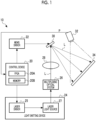
- Fig. 1 illustrates an example of a configuration of an image forming apparatus 10 of the present embodiment.
- the image forming apparatus 10 of the present embodiment comprises a control device 20, a MEMS driver 22, a light emitting device 24, a multiplexing optical system 26, a collimator 28, a MEMS mirror 30, and an imaging apparatus 32.
- the MEMS mirror 30 is an example of a "light scanning device" according to the embodiment of the disclosed technology.
- the light emitting device 24 includes a laser driver 25 and a laser light source 27.
- the laser driver 25 of the present embodiment drives the laser light source 27 based on an intensity modulation signal supplied from the control device 20 and causes laser light for forming an image to be output from the laser light source 27.
- the laser light source 27 outputs the laser light of three colors of red (R), green (G), and blue (B).
- the laser light is an example of "light" according to the embodiment of the disclosed technology.
- the laser light output from the laser light source 27 is multiplexed by the multiplexing optical system 26. Then, the MEMS mirror 30 is irradiated with the multiplexed laser light through the collimator 28. The laser light condensed in the MEMS mirror 30 is reflected toward a projection surface 34 by the MEMS mirror 30.
- the projection surface 34 is a screen for projecting the image, or a retina of an eye of a person. That is, the image forming apparatus 10 of the present embodiment is used for a projector, augmented reality (AR) glasses, and the like.
- the projection surface 34 is not limited to a surface of an actual object such as the screen and includes an imaginary plane in a space.
- the MEMS driver 22 drives the MEMS mirror 30 under control of the control device 20.
- a mirror portion 40 (refer to Fig. 2 ) that reflects laser light L swings about each of two axes orthogonal to each other as a central axis.
- the laser light L is scanned in a state of drawing a Lissajous curve on the projection surface 34 by the swing of the mirror portion 40 based on a driving signal.
- the Lissajous curve is a curve that is decided by a swing frequency about a first axis, a swing frequency about a second axis, and a phase difference therebetween.
- the mirror portion 40 is an example of a "movable mirror" according to the embodiment of the disclosed technology.
- the control device 20 of the present embodiment includes a field programmable gate array (FPGA) 20A and a memory 20B.
- the memory 20B is a volatile memory and stores various information such as an image signal representing the image projected to the projection surface 34.
- the memory 20B stores the image signal input from an outside of the image forming apparatus 10.
- the imaging apparatus 32 generates a captured image IP by imaging the projection surface 34 irradiated with the laser light L by the MEMS mirror 30, and outputs the generated captured image IP to the control device 20.
- the imaging apparatus 32 is configured with an image sensor such as a charge coupled device (CCD) image sensor or a complementary metal oxide semiconductor (CMOS) image sensor.
- the imaging apparatus 32 may be configured with a position sensitive detector (PSD).
- PSD position sensitive detector
- the captured image IP is used for correcting timings of a first reference signal and a second reference signal, described later.
- the captured image IP is an example of "imaging information" according to the embodiment of the disclosed technology.
- Fig. 2 illustrates an example of a configuration of the MEMS mirror 30.
- the MEMS mirror 30 includes the mirror portion 40, a first support portion 41, a first movable frame 42, a second support portion 43, a second movable frame 44, a connecting portion 45, and a fixed frame 46.
- the mirror portion 40 has a reflecting surface 40A on which an incidence ray is reflected.
- the reflecting surface 40A is formed with a thin metal film of gold (Au), aluminum (Al), silver (Ag), or a silver alloy.
- a shape of the reflecting surface 40A is a circular shape.
- the first support portion 41 is arranged outside the mirror portion 40 at each of positions that face with a second axis a 2 interposed therebetween.
- the first support portions 41 are connected to the mirror portion 40 on a first axis a 1 and support the mirror portion 40 in a swingable manner about the first axis a 1 .
- the first movable frame 42 is a rectangular frame surrounding the mirror portion 40 and is connected to the mirror portion 40 through the first support portions 41 on the first axis a 1 .
- a piezoelectric element 50 is formed on the first movable frame 42 at each of positions that face with the first axis a 1 interposed therebetween. In such a manner, a pair of first actuators 51 are configured by forming two piezoelectric elements 50 on the first movable frame 42.
- the pair of first actuators 51 are arranged at positions that face with the first axis a 1 interposed therebetween.
- the first actuators 51 cause the mirror portion 40 to swing about the first axis a 1 by applying rotational torque about the first axis a 1 to the mirror portion 40.
- the second support portion 43 is arranged outside the first movable frame 42 at each of positions that face with the first axis a 1 interposed therebetween.
- the second support portions 43 are connected to the first movable frame 42 on the second axis a 2 and support the first movable frame 42 and the mirror portion 40 in a swingable manner about the second axis a 2 .
- the second support portions 43 are torsion bars that stretch along the second axis a 2 .
- the second movable frame 44 is a rectangular frame surrounding the first movable frame 42 and is connected to the first movable frame 42 through the second support portions 43 on the second axis a 2 .
- the piezoelectric element 50 is formed on the second movable frame 44 at each of positions that face with the second axis a 2 interposed therebetween.
- a pair of second actuators 52 are configured by forming two piezoelectric elements 50 on the second movable frame 44.
- the pair of second actuators 52 are arranged at positions that face with the second axis a 2 interposed therebetween.
- the second actuators 52 cause the mirror portion 40 to swing about the second axis a 2 by applying rotational torque about the second axis a 2 to the mirror portion 40 and the first movable frame 42.
- the connecting portion 45 is arranged outside the second movable frame 44 at each of positions that face with the first axis a 1 interposed therebetween.
- the connecting portions 45 are connected to the second movable frame 44 on the second axis a 2 .
- the fixed frame 46 is a rectangular frame surrounding the second movable frame 44 and is connected to the second movable frame 44 through the connecting portions 45 on the second axis a 2 .
- the first axis a 1 and the second axis a 2 are orthogonal to each other.
- a direction parallel to the first axis a 1 will be referred to as an X direction
- a direction parallel to the second axis a 2 will be referred to as a Y direction
- a direction orthogonal to the first axis a 1 and the second axis a 2 will be referred to as a Z direction.
- Figs. 3A and 3B are diagrams for describing a deflection angle in a case where the mirror portion 40 swings.
- Fig. 3A illustrates a deflection angle (hereinafter, referred to as a first deflection angle) ⁇ 1 of the mirror portion 40 about the first axis a 1 .
- Fig. 3B illustrates a deflection angle (hereinafter, referred to as a second deflection angle) ⁇ 2 of the mirror portion 40 about the second axis a 2 .
- the first deflection angle ⁇ 1 is an angle at which a line normal to the reflecting surface 40A is inclined with respect to the Z direction in a YZ plane.
- the second deflection angle ⁇ 2 is an angle at which the line normal to the reflecting surface 40A is inclined with respect to the Z direction in an XZ plane.
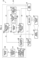
- Fig. 4 illustrates an example of a functional configuration of the control device 20.
- the control device 20 is configured with an image input portion 60, an information generation portion 61, an information storage portion 62, a first reference signal output portion 63A, a second reference signal output portion 63B, a light emission controller 64, a correction portion 65, a table holding portion 66, and a humidity and temperature sensor 67.
- the image input portion 60, the information generation portion 61, the information storage portion 62, the first reference signal output portion 63A, the second reference signal output portion 63B, the light emission controller 64, the correction portion 65, and the table holding portion 66 are functional portions implemented by causing the FPGA 20A and the memory 20B to operate in cooperation.
- Image data DT that represents the image to be formed is input into the image input portion 60 from the outside.
- the image corresponding to the image data DT input into the image input portion 60 may be referred to as an input image.
- the image data DT of colors represented by RGB signals is input into the image input portion 60.
- the image data DT input into the image input portion 60 is output to the information generation portion 61.
- the image data DT input into the image input portion 60 is not limited to the present embodiment and may be data corresponding to the image to be formed.
- the image data DT may be binarized data that represents whether or not to output the laser light L.
- the image data DT may be data that represents multiple values of an output amount.
- the information generation portion 61 generates intensity information SI that represents a correspondence relationship between a scanning position of the laser light L by the MEMS mirror 30 and a signal intensity of the input image.
- the signal intensity represents an intensity of each of the RGB signals.
- the information storage portion 62 stores the intensity information SI generated by the information generation portion 61.
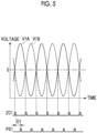
- the MEMS driver 22 outputs first driving signals V1A and V1B illustrated in Fig. 5 as an example to the pair of first actuators 51 of the MEMS mirror 30, and generates a first zero cross signal ZC1 and outputs the first zero cross signal ZC1 to the first reference signal output portion 63A.
- the first driving signal V1A and the first driving signal V1B are sine waves having a phase difference of 180°.
- the first zero cross signal ZC1 is a pulsed signal that represents points at which the first driving signals V1A and V1B become zero.
- Signals output to the first reference signal output portion 63A from the MEMS driver 22 are not limited to zero cross signals and may be signals having the same periods as the first driving signals V1A and V1B.
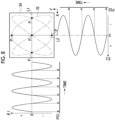
- the MEMS driver 22 outputs second driving signals V2A and V2B illustrated in Fig. 6 as an example to the pair of second actuators 52 of the MEMS mirror 30, and generates a second zero cross signal ZC2 and outputs the second zero cross signal ZC2 to the second reference signal output portion 63B.
- the second driving signal V2A and the second driving signal V2B are sine waves having a phase difference of 180°.
- the second zero cross signal ZC2 is a pulsed signal that represents points at which the second driving signals V2A and V2B become zero.
- Signals output to the second reference signal output portion 63B from the MEMS driver 22 are not limited to zero cross signals and may be signals having the same periods as the second driving signals V2A and V2B.
- a frequency (hereinafter, referred to as a first driving frequency) of the first driving signals V1A and V1B and a frequency (hereinafter, referred to as a second driving frequency) of the second driving signals V2A and V2B have different frequency ratios.
- a frequency ratio of the first driving frequency and the second driving frequency is decided based on a shape of a Lissajous curve of light scanning performed by the MEMS mirror 30.
- the first reference signal output portion 63A outputs a first reference signal PS1 to the light emission controller 64 by estimating a point in time when the first deflection angle ⁇ 1 of the mirror portion 40 becomes equal to a first reference angle.
- the first reference angle is set to 0°.
- the first reference signal output portion 63A generates the first reference signal PS1 by estimating the point in time when the first deflection angle ⁇ 1 becomes equal to the first reference angle, based on the first driving signals V1A and V1B.
- the first reference signal output portion 63A outputs a signal obtained by delaying the first zero cross signal ZC1 input from the MEMS driver 22 by a delay time period D1 as the first reference signal PS1.
- the delay time period D1 is ideally a time period corresponding to 1/4 of a period of the first zero cross signal ZC1.
- a shift occurs due to an environmental condition (a temperature, a humidity, and the like).
- the first reference signal output portion 63A acquires the delay time period D1 based on a temperature and a humidity detected by the humidity and temperature sensor 67 and a look-up table (hereinafter, referred to as the LUT) 66A held in the table holding portion 66, and generates the first reference signal PS1 based on the acquired delay time period D1.
- the LUT look-up table
- the second reference signal output portion 63B outputs a second reference signal PS2 to the light emission controller 64 by estimating a point in time when the second deflection angle ⁇ 2 of the mirror portion 40 becomes equal to a second reference angle.
- the second reference angle is set to 0°.
- the second reference signal output portion 63B generates the second reference signal PS2 by estimating the point in time when the second deflection angle ⁇ 2 becomes equal to the second reference angle, based on the second driving signals V2A and V2B.
- the second reference signal output portion 63B outputs a signal obtained by delaying the second zero cross signal ZC2 input from the MEMS driver 22 by a delay time period D2 as the second reference signal PS2.
- the delay time period D2 is ideally a time period corresponding to 1/4 of a period of the second zero cross signal ZC2.
- a shift occurs due to an environmental condition (a temperature, a humidity, and the like).
- the second reference signal output portion 63B acquires the delay time period D2 based on the temperature and the humidity detected by the humidity and temperature sensor 67 and the LUT 66A held in the table holding portion 66, and generates the second reference signal PS2 based on the acquired delay time period D2.
- a relationship among the delay time period D1, the temperature, and the humidity and a relationship among the delay time period D2, the temperature, and the humidity are recorded in advance in the LUT 66A.
- these relationships are decided based on a past history.
- the light emission controller 64 causes the light emitting device 24 to emit the laser light L based on the first reference signal PS1 and the second reference signal PS2.
- the light emission controller 64 reads out the intensity information SI from the information storage portion 62 and causes the light emitting device 24 to emit the laser light L having an intensity decided based on the first reference signal PS1 and the second reference signal PS2 for each constant time period (for example, for each clock period).
- a calibration mode for correcting the timings of the first reference signal PS1 and the second reference signal PS2 output by the first reference signal output portion 63A and the second reference signal output portion 63B, respectively, is performed.
- the light emission controller 64 causes the light emitting device 24 to emit the laser light L in accordance with the timing at which the first reference signal PS1 is output from the first reference signal output portion 63A, and the timing at which the second reference signal PS2 is output from the second reference signal output portion 63B.
- the light emission controller 64 causes the light emitting device 24 to emit the laser light L at the point in time when the first deflection angle ⁇ 1 is estimated to become equal to the first reference angle (in the present embodiment, 0°), and the point in time when the second deflection angle ⁇ 2 is estimated to become equal to the second reference angle (in the present embodiment, 0°).
- the imaging apparatus 32 images a pattern that is drawn on the projection surface 34 by reflecting the laser light L emitted from the light emitting device 24 by the MEMS mirror 30.
- the imaging apparatus 32 outputs the captured image IP generated by imaging the projection surface 34 to the correction portion 65.
- the correction portion 65 corrects the timings of the first reference signal PS1 and the second reference signal PS2 output by the first reference signal output portion 63A and the second reference signal output portion 63B, respectively, based on a shift amount of the pattern captured in the captured image IP from a predetermined shape.
- Fig. 8 illustrates an example of the pattern drawn on the projection surface 34 in the calibration mode.
- the frequency ratio of the first driving frequency and the second driving frequency is set to 3:2 for simplification of description.
- a Lissajous curve 70 is drawn on the projection surface 34 by the light scanning performed by the MEMS mirror 30.
- Fig. 8 illustrates a case where a shift does not occur between the swing of the mirror portion 40 and the timings of the first reference signal PS1 and the second reference signal PS2.
- a first reference line L1 and a second reference line L2 on the projection surface 34 are irradiated with the laser light L.
- the first reference line L1 is a straight line that passes through a center of the Lissajous curve 70 and is parallel to the X direction.
- the second reference line L2 is a straight line that passes through the center of the Lissajous curve 70 and is parallel to the Y direction.
- Reference numeral P denotes a point (that is, a bright point) irradiated with the laser light L on the projection surface 34.
- the bright points P draw straight line patterns along the first reference line L1 and the second reference line L2.
- Fig. 9 illustrates a case where a shift occurs between the swing of the mirror portion 40 and the timings of the first reference signal PS1 and the second reference signal PS2.
- positions shifted from the first reference line L1 and the second reference line L2 on the projection surface 34 are irradiated with the laser light L.
- straight lines L1A and L1B shifted from the first reference line L1 and straight lines L2A and L2B shifted from the second reference line L2 are irradiated with the laser light L.
- the straight line L1A is a line that is irradiated with the laser light L on an advancing path of Lissajous scanning.
- the straight line L1B is a line that is irradiated with the laser light L on a returning path of the Lissajous scanning.
- the straight line L2A is a line that is irradiated with the laser light L on the advancing path of the Lissajous scanning.
- the straight line L2B is a line that is irradiated with the laser light L on the returning path of the Lissajous scanning.
- the advancing path refers to a path along which the first deflection angle ⁇ 1 is increased for the Y direction, and a path along which the second deflection angle ⁇ 2 is increased for the X direction.
- the returning path refers to a path along which the first deflection angle ⁇ 1 is decreased for the Y direction, and a path along which the second deflection angle ⁇ 2 is decreased for the X direction.
- the first reference line L1 is separated into the straight line L1A and the straight line L1B
- the second reference line L2 is separated into the straight line L2A and the straight line L2B.
- the bright points P draw straight line patterns along the straight line L1A, the straight line L1B, the straight line L2A, and the straight line L2B.
- Fig. 10 illustrates an example of a functional configuration of the correction portion 65.
- the correction portion 65 includes a correction amount calculation portion 72 and a signal correction portion 73.
- the captured image IP is input into the correction portion 65 from the imaging apparatus 32.
- the correction amount calculation portion 72 derives the correction amounts ⁇ 1 and ⁇ 2 based on a relationship between the shift amount ⁇ X and the correction amount ⁇ 1 and a relationship between the shift amount ⁇ Y and the correction amount ⁇ 2 stored in advance.
- Each of the relationship between the shift amount ⁇ X and the correction amount ⁇ 1 and the relationship between the shift amount ⁇ Y and the correction amount ⁇ 2 is an almost proportional relationship.
- the signal correction portion 73 corrects the timing of the first reference signal PS1 output from the first reference signal output portion 63A based on the correction amount ⁇ 1 input from the correction amount calculation portion 72, and corrects the timing of the second reference signal PS2 output from the second reference signal output portion 63B based on the correction amount ⁇ 2 input from the correction amount calculation portion 72.
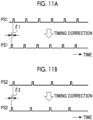
- Figs. 11A and 11B illustrate an example of timing correction performed by the signal correction portion 73.
- Fig. 11A illustrates an example of correcting the timing of the first reference signal PS1 based on the correction amount 61.
- Fig. 11B illustrates an example of correcting the timing of the second reference signal PS2 based on the correction amount ⁇ 2.
- the signal correction portion 73 may be provided inside each of the first reference signal output portion 63A and the second reference signal output portion 63B.
- the first reference signal output portion 63A corrects the timing of the first reference signal PS1 based on the correction amount ⁇ 1 input from the correction amount calculation portion 72.
- the second reference signal output portion 63B corrects the timing of the second reference signal PS2 based on the correction amount ⁇ 2 input from the correction amount calculation portion 72.
- the calibration mode is executed for a predetermined period when the image forming apparatus 10 is started. After the calibration mode is finished, the first reference signal output portion 63A and the second reference signal output portion 63B continue the timing correction based on the correction amounts ⁇ 1 and ⁇ 2 in the drawing mode.
- the calibration mode may be periodically executed during execution of the drawing mode.
- the image forming apparatus 10 can suppress distortion of the image drawn on the projection surface 34 by correcting the timings of the first reference signal PS1 and the second reference signal PS2 based on the imaging information acquired by the imaging apparatus 32.
- first reference line L1 and the second reference line L2 are set to pass through the center of the Lissajous curve 70 as illustrated in Fig. 8 , setting positions of the first reference line L1 and the second reference line L2 are not limited thereto and can be appropriately changed.
- the positions of the first reference line L1 and the second reference line L2 may be set in an end part of a drawing region of the laser light L.
- the first reference line L1 and the second reference line L2 are irradiated with the laser light L.
- the straight lines L1A and L1B shifted from the first reference line L1 and the straight lines L2A and L2B shifted from the second reference line L2 are irradiated with the laser light L.
- the correction portion 65 in the same manner as the embodiment, corrects the timings of the first reference signal PS1 and the second reference signal PS2 so that the straight line L1A matches the straight line L1B, and the straight line L2A matches the straight line L2B.
- the irradiation with the laser light L is performed on the advancing path and the returning path of the Lissajous scanning. Accordingly, in a case where a shift occurs as described above, the first reference line L1 is separated into the straight line L1A and the straight line L1B, and the second reference line L2 is separated into the straight line L2A and the straight line L2B. Instead, the irradiation with the laser light L may be performed on only one of the advancing path and the returning path of the Lissaj ous scanning.
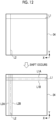
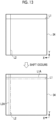
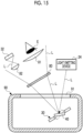
- Fig. 13 illustrates an example of performing the irradiation with the laser light L on only the advancing path in a case where the positions of the first reference line L1 and the second reference line L2 are set in the end part of the drawing region of the laser light L.
- the straight line L1A shifted from the first reference line L1 and the straight line L2A shifted from the second reference line L2 are irradiated with the laser light L.
- the correction portion 65 may correct the timings of the first reference signal PS1 and the second reference signal PS2 so that the straight line L1A matches the first reference line L1, and the straight line L2A matches the second reference line L2.
- the irradiation with the laser light L is performed a plurality of times in one scanning period of the Lissajous scanning.
- One scanning period of the Lissajous scanning corresponds to a frame period of the image projected to the projection surface 34.
- the number of times the irradiation with the laser light L is performed in one scanning period of the Lissajous scanning may be once (that is, one pulse).
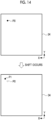
- Fig. 14 illustrates an example of performing the irradiation with the laser light L only once in one scanning period of the Lissajous scanning.
- a reference point P0 is irradiated with the laser light L.
- a point P1 shifted from the reference point P0 is irradiated with the laser light L.
- the correction portion 65 may correct the timings of the first reference signal PS1 and the second reference signal PS2 so that the point P1 matches the reference point P0.
- the reference point P0 may be set as a point at which the Lissajous curve 70 intersects.
- the irradiation with the laser light L is performed each time the Lissajous scanning passes through the reference point P0 (that is, the irradiation with the laser light L is performed twice in one scanning period of the Lissajous scanning).
- the reference point P0 is separated into two points.
- the correction portion 65 may correct the timings of the first reference signal PS1 and the second reference signal PS2 so that the two separated points match.
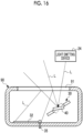
- a first optical element 80 having a light diffusion function is provided on an optical path of the laser light L reflected by the MEMS mirror 30.
- the first optical element 80 has a function of expanding a so-called eye-box (a range in which a video can be viewed by moving eyes).
- the laser light L emitted from the light emitting device 24 is incident on the MEMS mirror 30.
- the laser light L incident on the MEMS mirror 30 is emitted toward the first optical element 80 by modulating a reflection direction by the swinging mirror portion 40.
- the first optical element 80 transmits and diffuses the laser light L incident from the MEMS mirror 30.
- the first optical element 80 is a microlens array.
- the first optical element 80 is not limited to a microlens array and may be an optical element such as a frosted glass, a grating, or a hologram or may be a combination thereof.
- a second optical element 81 for guiding the laser light L to an eyeball E is provided on the optical path of the laser light L transmitted through the first optical element 80.
- a third optical element 82 for guiding a part of the laser light L to the imaging apparatus 32 is provided on the optical path of the laser light L transmitted through the first optical element 80.
- the third optical element 82 condenses the part of the laser light L transmitted through the first optical element 80 and forms an image of the condensed part of the laser light L on an imaging surface of the imaging apparatus 32.
- the third optical element 82 since the laser light L is diffused by the first optical element 80, it is preferable to provide the third optical element 82 that condenses the laser light L.
- the third optical element 82 is an example of an "optical element that guides a part of light to an imaging apparatus" according to the embodiment of the disclosed technology.
- the second optical element 81 and the third optical element 82 are lenses formed of glass or resin.
- the second optical element 81 and the third optical element 82 are not limited to lenses and may be optical elements such as holograms or concave mirrors or may be a combination thereof. It is preferable to configure the third optical element 82 with a hologram from a viewpoint of size reduction compared to a case of configuring the third optical element 82 with a liquid crystal or the like.
- the MEMS mirror 30 is accommodated in a package 90.
- An inside of the package 90 is depressurized or is in a vacuum in order to decrease air resistance of the swinging mirror portion 40.
- the package 90 is formed of glass. At least a part of the package 90 has light transmittance. The laser light L emitted from the light emitting device 24 is incident on the MEMS mirror 30 through a light transmission portion 91 of the package 90, and the laser light L reflected by the mirror portion 40 is emitted to the outside through the light transmission portion 91.
- the imaging apparatus 32 may be provided inside the package 90.
- the imaging apparatus 32 is provided on the optical path of the laser light L reflected on a surface of the light transmission portion 91 out of the laser light L reflected by the mirror portion 40.
- the imaging apparatus 32 receives the laser light L before the laser light L is diffused.
- the captured image IP generated by performing an imaging operation by the imaging apparatus 32 is output to the outside through a lead terminal 35. In such a manner, size reduction of the image forming apparatus 10 can be achieved by accommodating the imaging apparatus 32 inside the package 90.
- the light transmission portion 91 is an example of the "optical element that guides the part of the light to the imaging apparatus" according to the embodiment of the disclosed technology.
- first reference angle and the second reference angle may be angles other than 0°.
- the first reference angle may be set as an angle at which the first deflection angle ⁇ 1 is the maximum or minimum
- the second reference angle may be set as an angle at which the second deflection angle ⁇ 2 is the maximum or minimum.
- four reference lines L1 to L4 are irradiated with the laser light L on the projection surface 34.
- the reference lines L1 to L4 are straight lines tangential to an outer shape of the Lissajous curve 70.
- the correction portion 65 may correct the timings of the first reference signal PS1 and the second reference signal PS2 based on displacement amounts of the bright points P from the reference lines L1 to L4 that are derived using the captured image IP.
- the first reference signal output portion 63A outputs the first reference signal PS1 by estimating the point in time when the first deflection angle ⁇ 1 becomes equal to the first reference angle, using the temperature and the humidity detected by the humidity and temperature sensor 67 and the LUT 66A.
- the first reference signal output portion 63A may output the first reference signal PS1 by estimating the point in time when the first deflection angle ⁇ 1 becomes equal to the first reference angle, based on an angle sensor (not illustrated) that detects the first deflection angle ⁇ 1.
- the second reference signal output portion 63B may output the second reference signal PS2 by estimating the point in time when the second deflection angle ⁇ 2 becomes equal to the second reference angle, based on an angle sensor (not illustrated) that detects the second deflection angle ⁇ 2.
- the MEMS mirror 30 of two axes is used as the light scanning device in implementations not according to the claimed subject matter, a MEMS mirror of one axis may be used as the light scanning device. Accordingly, the disclosed technology can also be applied to an image forming apparatus comprising a light scanning device of one axis in which a movable mirror swings about a first axis.
- the following various processors can be used as a hardware structure of a processing unit that executes various processing of the image input portion 60, the information generation portion 61, the information storage portion 62, the first reference signal output portion 63A, the second reference signal output portion 63B, the light emission controller 64, the correction portion 65, and the table holding portion 66.
- the various processors include, in addition to a central processing unit (CPU) that is a general-purpose processor functioning as various processing units by executing software (program), a programmable logic device (PLD) such as the FPGA that is a processor having a circuit configuration changeable after manufacturing, a dedicated electric circuit such as an application specific integrated circuit (ASIC) that is a processor having a circuit configuration dedicatedly designed to execute specific processing, and the like.
- CPU central processing unit
- PLD programmable logic device
- FPGA programmable logic device
- ASIC application specific integrated circuit
- One processing unit may be configured with one of the various processors or may be configured with a combination of two or more processors of the same type or different types (for example, a combination of a plurality of FPGAs and/or a combination of a CPU and an FPGA).
- a plurality of processing units may be configured with one processor.
- Examples of the plurality of processing units configured with one processor include, first, as represented by a computer such as a client and a server, a form in which one processor is configured with a combination of one or more CPUs and software, and the processor functions as the plurality of processing units. Second, as represented by a system on chip (SoC) or the like, a form of using a processor that implements functions of the entire system including the plurality of processing units by one integrated circuit (IC) chip is included. In such a manner, various processing units are configured using one or more of the various processors as a hardware structure.
- SoC system on chip
- an electric circuit in which circuit elements such as semiconductor elements are combined can be used as the hardware structure of the various processors.
Landscapes
- Physics & Mathematics (AREA)
- Optics & Photonics (AREA)
- General Physics & Mathematics (AREA)
- Engineering & Computer Science (AREA)
- Multimedia (AREA)
- Signal Processing (AREA)
- Mechanical Optical Scanning Systems (AREA)
- Transforming Electric Information Into Light Information (AREA)
- Mechanical Light Control Or Optical Switches (AREA)
Claims (5)
- Bilderzeugungsgerät (10), umfassend:eine Licht emittierende Vorrichtung (24), die Licht emittiert;einen beweglichen Spiegel (40), der das von der Licht emittierenden Vorrichtung (24) emittierte Licht reflektiert,einen ersten Aktuator (51), der bewirkt, dass der bewegliche Spiegel (40) um eine erste Achse (a1) schwingt;einen zweiten Aktuator (52), der bewirkt, dass der bewegliche Spiegel (40) um eine zweite Achse (a2) schwingt;einen ersten Referenzsignalausgabeabschnitt (63A), der ein erstes Referenzsignal ausgibt, indem er einen Zeitpunkt schätzt, zu dem ein Ablenkwinkel des beweglichen Spiegels (40) um die erste Achse (a1) gleich einem ersten Referenzwinkel wird, wobei der erste Referenzsignalausgabeabschnitt (63A) den Zeitpunkt, zu dem der Ablenkwinkel des beweglichen Spiegels (40) um die erste Achse (a1) gleich dem ersten Referenzwinkel wird, basierend auf einem ersten Antriebssignal schätzt, das dem ersten Aktuator (51) bereitgestellt wird;einen zweiten Referenzsignalausgabeabschnitt (63B), der ein zweites Referenzsignal ausgibt, indem er einen Zeitpunkt schätzt, zu dem ein Ablenkwinkel des beweglichen Spiegels (40) um die zweite Achse (a2) gleich einem zweiten Referenzwinkel wird, wobei der zweite Referenzsignalausgabeabschnitt (63B) den Zeitpunkt, zu dem der Ablenkwinkel des beweglichen Spiegels (40) um die zweite Achse (a2) gleich dem zweiten Referenzwinkel wird, basierend auf einem zweiten Antriebssignal schätzt, das dem zweiten Aktuator (52) bereitgestellt wird;eine Lichtemissionssteuerung (64), die bewirkt, dass die Licht emittierende Vorrichtung (24) das Licht basierend auf dem ersten Referenzsignal, das von dem ersten Referenzsignalausgabeabschnitt (63A) ausgegeben wird, emittiert;ein Bildgebungsgerät (32), das das durch den beweglichen Spiegel (40) reflektierte Licht abbildet; undeinen Korrekturabschnitt (65), der eine zeitliche Planung des durch den ersten Referenzsignalausgabeabschnitt (63A) ausgegebenen ersten Referenzsignals und eine zeitliche Planung des durch den zweiten Referenzsignalausgabeabschnitt (63B) ausgegebenen zweiten Referenzsignals basierend auf durch das Bildgebungsgerät (32) erfassten Bildgebungsinformationen korrigiert.
- Bilderzeugungsgerät (10) nach Anspruch 1,
wobei der erste Referenzwinkel ein Winkel ist, bei dem der Ablenkwinkel des beweglichen Spiegels (40) um die erste Achse (a1) null wird, und der zweite Referenzwinkel ein Winkel ist, bei dem der Ablenkwinkel des beweglichen Spiegels (40) um die zweite Achse (a2) null wird. - Bilderzeugungsgerät (10) nach Anspruch 1,
wobei der erste Referenzwinkel ein Winkel ist, bei dem der Ablenkwinkel des beweglichen Spiegels (40) um die erste Achse (a1) das Maximum oder Minimum ist, und der zweite Referenzwinkel ein Winkel ist, bei dem der Ablenkwinkel des beweglichen Spiegels (40) um die zweite Achse (a2) das Maximum oder Minimum ist. - Bilderzeugungsgerät (10) nach einem der Ansprüche 1 bis 3, ferner umfassend:
ein optisches Element, das einen Teil des Lichts zu dem Bildgebungsgerät (32) auf einem optischen Pfad des durch den beweglichen Spiegel (40) reflektierten Lichts leitet. - Betriebsverfahren für ein Bilderzeugungsgerät (10), das eine Licht emittierende Vorrichtung (24), die Licht emittiert, einen beweglichen Spiegel (40), der das von der Licht emittierenden Vorrichtung (24) emittierte Licht reflektiert, einen ersten Aktuator (51), der bewirkt, dass der bewegliche Spiegel (40) um eine erste Achse (a1) schwingt, einen zweiten Aktuator (52), der bewirkt, dass der bewegliche Spiegel (40) um eine zweite Achse (a2) schwingt, einen ersten Referenzsignalausgabeabschnitt (63A), der ein erstes Referenzsignal ausgibt, indem er einen Zeitpunkt schätzt, zu dem ein Ablenkwinkel des beweglichen Spiegels (40) um die erste Achse (a1) gleich einem ersten Referenzwinkel wird, wobei der erste Referenzsignalausgabeabschnitt (63A) den Zeitpunkt, zu dem der Ablenkwinkel des beweglichen Spiegels (40) um die erste Achse (a1) gleich dem ersten Referenzwinkel wird, basierend auf einem ersten Antriebssignal schätzt, das dem ersten Aktuator (51) bereitgestellt wird, einen zweiten Referenzsignalausgabeabschnitt (63B), der ein zweites Referenzsignal ausgibt, indem er einen Zeitpunkt schätzt, zu dem ein Ablenkwinkel des beweglichen Spiegels (40) um die zweite Achse (a2) gleich einem zweiten Referenzwinkel wird, wobei der zweite Referenzsignalausgabeabschnitt (63B) den Zeitpunkt, zu dem der Ablenkwinkel des beweglichen Spiegels (40) um die zweite Achse (a2) gleich dem zweiten Referenzwinkel wird, basierend auf einem zweiten Antriebssignal schätzt, das dem zweiten Aktuator (52) bereitgestellt wird, eine Lichtemissionssteuerung (64), die bewirkt, dass die Licht emittierende Vorrichtung (24) das Licht basierend auf dem ersten Referenzsignal, das von dem ersten Referenzsignalausgabeabschnitt (63A) ausgegeben wird, emittiert, und ein Bildgebungsgerät (32), das das durch den beweglichen Spiegel (40) reflektierte Licht abbildet, enthält, wobei das Betriebsverfahren Folgendes umfasst:
Korrigieren einer zeitlichen Planung des durch den ersten Referenzsignalausgabeabschnitt (63A) ausgegebenen ersten Referenzsignals und einer zeitlichen Planung des durch den zweiten Referenzsignalausgabeabschnitt (63B) ausgegebenen zweiten Referenzsignals basierend auf durch das Bildgebungsgerät (32) erfassten Bildgebungsinformationen.
Applications Claiming Priority (1)
| Application Number | Priority Date | Filing Date | Title |
|---|---|---|---|
| JP2021095860A JP7640373B2 (ja) | 2021-06-08 | 2021-06-08 | 画像形成装置、及びその作動方法 |
Publications (2)
| Publication Number | Publication Date |
|---|---|
| EP4102287A1 EP4102287A1 (de) | 2022-12-14 |
| EP4102287B1 true EP4102287B1 (de) | 2024-10-23 |
Family
ID=81877966
Family Applications (1)
| Application Number | Title | Priority Date | Filing Date |
|---|---|---|---|
| EP22176640.5A Active EP4102287B1 (de) | 2021-06-08 | 2022-06-01 | Bilderzeugungsgerät und betriebsverfahren dafür |
Country Status (4)
| Country | Link |
|---|---|
| US (1) | US12320970B2 (de) |
| EP (1) | EP4102287B1 (de) |
| JP (1) | JP7640373B2 (de) |
| CN (1) | CN115453744A (de) |
Family Cites Families (14)
| Publication number | Priority date | Publication date | Assignee | Title |
|---|---|---|---|---|
| JPS569763A (en) | 1979-07-06 | 1981-01-31 | Canon Inc | Beam recording device |
| JP4316273B2 (ja) | 2003-03-31 | 2009-08-19 | 日本信号株式会社 | 光走査装置及びその光ビーム発射タイミング調整方法 |
| JP2005242036A (ja) | 2004-02-27 | 2005-09-08 | Canon Inc | 画像投射装置、および画像投射装置の制御方法 |
| KR100682955B1 (ko) * | 2006-01-06 | 2007-02-15 | 삼성전자주식회사 | 스캐너의 구동특성 평가장치 및 방법 |
| JP5221965B2 (ja) * | 2008-01-29 | 2013-06-26 | キヤノン株式会社 | 二次元走査装置、及び投射型画像表示装置 |
| DE102008043416A1 (de) | 2008-11-03 | 2010-05-06 | Robert Bosch Gmbh | Mikromechanisches Bauteil und Verfahren zum Betreiben eines mikromechanischen Bauteils |
| US8559086B2 (en) | 2010-02-17 | 2013-10-15 | Microvision, Inc. | Piezoresistive sensors for MEMS device having rejection of undesired motion |
| CN102472895B (zh) * | 2010-04-20 | 2014-08-13 | 松下电器产业株式会社 | 图像显示装置 |
| JP2015022206A (ja) * | 2013-07-22 | 2015-02-02 | 船井電機株式会社 | 振動ミラー素子および距離計測装置 |
| JP6387589B2 (ja) * | 2013-08-30 | 2018-09-12 | 株式会社リコー | 画像形成装置、車両、及び画像形成装置の制御方法 |
| JP2019164213A (ja) * | 2018-03-19 | 2019-09-26 | 株式会社リコー | 光走査装置、画像投写装置、移動体、及び、光走査装置の製造方法 |
| JP2020039082A (ja) | 2018-09-05 | 2020-03-12 | セイコーエプソン株式会社 | 表示装置、表示システムおよび表示装置の制御方法 |
| US10939080B2 (en) | 2019-03-29 | 2021-03-02 | Facebook Technologies, Llc | Trajectory estimation for a MEMS reflector |
| JP7361552B2 (ja) * | 2019-09-24 | 2023-10-16 | キヤノン株式会社 | 光走査装置及び画像形成装置 |
-
2021
- 2021-06-08 JP JP2021095860A patent/JP7640373B2/ja active Active
-
2022
- 2022-06-01 EP EP22176640.5A patent/EP4102287B1/de active Active
- 2022-06-02 US US17/830,862 patent/US12320970B2/en active Active
- 2022-06-02 CN CN202210619921.0A patent/CN115453744A/zh active Pending
Also Published As
| Publication number | Publication date |
|---|---|
| CN115453744A (zh) | 2022-12-09 |
| US12320970B2 (en) | 2025-06-03 |
| JP2022187717A (ja) | 2022-12-20 |
| US20220390739A1 (en) | 2022-12-08 |
| JP7640373B2 (ja) | 2025-03-05 |
| EP4102287A1 (de) | 2022-12-14 |
Similar Documents
| Publication | Publication Date | Title |
|---|---|---|
| US10634904B2 (en) | Image projection device | |
| EP3589999B1 (de) | Anzeigevorrichtung zum mems-scanning | |
| US12320971B2 (en) | Optical scanning device, driving method of optical scanning device, and image drawing system | |
| US12282155B2 (en) | Optical scanning device, driving method of optical scanning device, and image drawing system | |
| JP2017078756A (ja) | ヘッドマウントディスプレイ装置 | |
| WO2006019028A1 (ja) | 瞳孔検出装置およびそれを備えた画像表示装置 | |
| CN110832380B (zh) | 用于校准数据眼镜的投影装置的方法以及用于执行方法的数据眼镜的投影装置 | |
| US12003898B2 (en) | Projector and projection method | |
| US20210109342A1 (en) | Light deflector, deflecting device, distance-measuring apparatus, image projection device, and vehicle | |
| US20210041693A1 (en) | Information detection apparatus, video projection apparatus, information detection method, and video projection method | |
| CN112485904A (zh) | 眼睛调节距离测量设备和方法及头戴式显示器 | |
| CN114127617A (zh) | 用于具有高精度和实时对象跟踪的3d姿态测量的系统和方法 | |
| EP4102287B1 (de) | Bilderzeugungsgerät und betriebsverfahren dafür | |
| CN112587088B (zh) | 眼科成像设备 | |
| EP4102286B1 (de) | Lichtabtastungsvorrichtung und bilderzeugungsvorrichtung | |
| JP7707281B2 (ja) | 制御装置、画像形成装置、及び制御方法 | |
| CN111123625B (zh) | 投影仪及投影方法 | |
| JP2021081593A (ja) | 台座、可動装置、レーザレーダ装置、画像形成装置及び画像投影装置 | |
| US12302041B2 (en) | Optical scanning device, driving method of optical scanning device, and image drawing system | |
| JP3672731B2 (ja) | レンジファインダ装置 | |
| US12401771B2 (en) | Optical scanning device, driving method of optical scanning device, and image drawing system | |
| JP5340562B2 (ja) | 角膜顕微鏡装置 | |
| JP2018165810A (ja) | 発光装置および測距システム | |
| US20250180888A1 (en) | Method for aligning and/or positioning a laser module of a laser projector, laser projector, and aligning and/or positioning device | |
| US20240019689A1 (en) | Control system, optical deflection apparatus, image projection apparatus, mobile object, and head-mounted display |
Legal Events
| Date | Code | Title | Description |
|---|---|---|---|
| PUAI | Public reference made under article 153(3) epc to a published international application that has entered the european phase |
Free format text: ORIGINAL CODE: 0009012 |
|
| STAA | Information on the status of an ep patent application or granted ep patent |
Free format text: STATUS: THE APPLICATION HAS BEEN PUBLISHED |
|
| AK | Designated contracting states |
Kind code of ref document: A1 Designated state(s): AL AT BE BG CH CY CZ DE DK EE ES FI FR GB GR HR HU IE IS IT LI LT LU LV MC MK MT NL NO PL PT RO RS SE SI SK SM TR |
|
| STAA | Information on the status of an ep patent application or granted ep patent |
Free format text: STATUS: REQUEST FOR EXAMINATION WAS MADE |
|
| 17P | Request for examination filed |
Effective date: 20230228 |
|
| RBV | Designated contracting states (corrected) |
Designated state(s): AL AT BE BG CH CY CZ DE DK EE ES FI FR GB GR HR HU IE IS IT LI LT LU LV MC MK MT NL NO PL PT RO RS SE SI SK SM TR |
|
| GRAP | Despatch of communication of intention to grant a patent |
Free format text: ORIGINAL CODE: EPIDOSNIGR1 |
|
| STAA | Information on the status of an ep patent application or granted ep patent |
Free format text: STATUS: GRANT OF PATENT IS INTENDED |
|
| INTG | Intention to grant announced |
Effective date: 20240719 |
|
| RIN1 | Information on inventor provided before grant (corrected) |
Inventor name: SONODA, SHINICHIRO Inventor name: TANAKA, NOBUYA |
|
| GRAS | Grant fee paid |
Free format text: ORIGINAL CODE: EPIDOSNIGR3 |
|
| GRAA | (expected) grant |
Free format text: ORIGINAL CODE: 0009210 |
|
| STAA | Information on the status of an ep patent application or granted ep patent |
Free format text: STATUS: THE PATENT HAS BEEN GRANTED |
|
| P01 | Opt-out of the competence of the unified patent court (upc) registered |
Free format text: CASE NUMBER: APP_49488/2024 Effective date: 20240830 |
|
| AK | Designated contracting states |
Kind code of ref document: B1 Designated state(s): AL AT BE BG CH CY CZ DE DK EE ES FI FR GB GR HR HU IE IS IT LI LT LU LV MC MK MT NL NO PL PT RO RS SE SI SK SM TR |
|
| REG | Reference to a national code |
Ref country code: GB Ref legal event code: FG4D |
|
| REG | Reference to a national code |
Ref country code: CH Ref legal event code: EP |
|
| REG | Reference to a national code |
Ref country code: DE Ref legal event code: R096 Ref document number: 602022006990 Country of ref document: DE |
|
| REG | Reference to a national code |
Ref country code: IE Ref legal event code: FG4D |
|
| REG | Reference to a national code |
Ref country code: LT Ref legal event code: MG9D |
|
| REG | Reference to a national code |
Ref country code: NL Ref legal event code: MP Effective date: 20241023 |
|
| REG | Reference to a national code |
Ref country code: AT Ref legal event code: MK05 Ref document number: 1735303 Country of ref document: AT Kind code of ref document: T Effective date: 20241023 |
|
| PG25 | Lapsed in a contracting state [announced via postgrant information from national office to epo] |
Ref country code: NL Free format text: LAPSE BECAUSE OF FAILURE TO SUBMIT A TRANSLATION OF THE DESCRIPTION OR TO PAY THE FEE WITHIN THE PRESCRIBED TIME-LIMIT Effective date: 20241023 |
|
| PG25 | Lapsed in a contracting state [announced via postgrant information from national office to epo] |
Ref country code: NL Free format text: LAPSE BECAUSE OF FAILURE TO SUBMIT A TRANSLATION OF THE DESCRIPTION OR TO PAY THE FEE WITHIN THE PRESCRIBED TIME-LIMIT Effective date: 20241023 |
|
| PG25 | Lapsed in a contracting state [announced via postgrant information from national office to epo] |
Ref country code: HR Free format text: LAPSE BECAUSE OF FAILURE TO SUBMIT A TRANSLATION OF THE DESCRIPTION OR TO PAY THE FEE WITHIN THE PRESCRIBED TIME-LIMIT Effective date: 20241023 Ref country code: IS Free format text: LAPSE BECAUSE OF FAILURE TO SUBMIT A TRANSLATION OF THE DESCRIPTION OR TO PAY THE FEE WITHIN THE PRESCRIBED TIME-LIMIT Effective date: 20250223 Ref country code: PT Free format text: LAPSE BECAUSE OF FAILURE TO SUBMIT A TRANSLATION OF THE DESCRIPTION OR TO PAY THE FEE WITHIN THE PRESCRIBED TIME-LIMIT Effective date: 20250224 |
|
| PG25 | Lapsed in a contracting state [announced via postgrant information from national office to epo] |
Ref country code: FI Free format text: LAPSE BECAUSE OF FAILURE TO SUBMIT A TRANSLATION OF THE DESCRIPTION OR TO PAY THE FEE WITHIN THE PRESCRIBED TIME-LIMIT Effective date: 20241023 |
|
| PG25 | Lapsed in a contracting state [announced via postgrant information from national office to epo] |
Ref country code: BG Free format text: LAPSE BECAUSE OF FAILURE TO SUBMIT A TRANSLATION OF THE DESCRIPTION OR TO PAY THE FEE WITHIN THE PRESCRIBED TIME-LIMIT Effective date: 20241023 |
|
| PG25 | Lapsed in a contracting state [announced via postgrant information from national office to epo] |
Ref country code: ES Free format text: LAPSE BECAUSE OF FAILURE TO SUBMIT A TRANSLATION OF THE DESCRIPTION OR TO PAY THE FEE WITHIN THE PRESCRIBED TIME-LIMIT Effective date: 20241023 |
|
| PG25 | Lapsed in a contracting state [announced via postgrant information from national office to epo] |
Ref country code: NO Free format text: LAPSE BECAUSE OF FAILURE TO SUBMIT A TRANSLATION OF THE DESCRIPTION OR TO PAY THE FEE WITHIN THE PRESCRIBED TIME-LIMIT Effective date: 20250123 |
|
| PG25 | Lapsed in a contracting state [announced via postgrant information from national office to epo] |
Ref country code: LV Free format text: LAPSE BECAUSE OF FAILURE TO SUBMIT A TRANSLATION OF THE DESCRIPTION OR TO PAY THE FEE WITHIN THE PRESCRIBED TIME-LIMIT Effective date: 20241023 Ref country code: AT Free format text: LAPSE BECAUSE OF FAILURE TO SUBMIT A TRANSLATION OF THE DESCRIPTION OR TO PAY THE FEE WITHIN THE PRESCRIBED TIME-LIMIT Effective date: 20241023 Ref country code: GR Free format text: LAPSE BECAUSE OF FAILURE TO SUBMIT A TRANSLATION OF THE DESCRIPTION OR TO PAY THE FEE WITHIN THE PRESCRIBED TIME-LIMIT Effective date: 20250124 |
|
| PG25 | Lapsed in a contracting state [announced via postgrant information from national office to epo] |
Ref country code: PL Free format text: LAPSE BECAUSE OF FAILURE TO SUBMIT A TRANSLATION OF THE DESCRIPTION OR TO PAY THE FEE WITHIN THE PRESCRIBED TIME-LIMIT Effective date: 20241023 |
|
| PG25 | Lapsed in a contracting state [announced via postgrant information from national office to epo] |
Ref country code: RS Free format text: LAPSE BECAUSE OF FAILURE TO SUBMIT A TRANSLATION OF THE DESCRIPTION OR TO PAY THE FEE WITHIN THE PRESCRIBED TIME-LIMIT Effective date: 20250123 |
|
| PG25 | Lapsed in a contracting state [announced via postgrant information from national office to epo] |
Ref country code: SM Free format text: LAPSE BECAUSE OF FAILURE TO SUBMIT A TRANSLATION OF THE DESCRIPTION OR TO PAY THE FEE WITHIN THE PRESCRIBED TIME-LIMIT Effective date: 20241023 |
|
| PGFP | Annual fee paid to national office [announced via postgrant information from national office to epo] |
Ref country code: DE Payment date: 20250429 Year of fee payment: 4 |
|
| PG25 | Lapsed in a contracting state [announced via postgrant information from national office to epo] |
Ref country code: DK Free format text: LAPSE BECAUSE OF FAILURE TO SUBMIT A TRANSLATION OF THE DESCRIPTION OR TO PAY THE FEE WITHIN THE PRESCRIBED TIME-LIMIT Effective date: 20241023 |
|
| PG25 | Lapsed in a contracting state [announced via postgrant information from national office to epo] |
Ref country code: EE Free format text: LAPSE BECAUSE OF FAILURE TO SUBMIT A TRANSLATION OF THE DESCRIPTION OR TO PAY THE FEE WITHIN THE PRESCRIBED TIME-LIMIT Effective date: 20241023 |
|
| PG25 | Lapsed in a contracting state [announced via postgrant information from national office to epo] |
Ref country code: RO Free format text: LAPSE BECAUSE OF FAILURE TO SUBMIT A TRANSLATION OF THE DESCRIPTION OR TO PAY THE FEE WITHIN THE PRESCRIBED TIME-LIMIT Effective date: 20241023 |
|
| REG | Reference to a national code |
Ref country code: DE Ref legal event code: R097 Ref document number: 602022006990 Country of ref document: DE |
|
| PG25 | Lapsed in a contracting state [announced via postgrant information from national office to epo] |
Ref country code: SK Free format text: LAPSE BECAUSE OF FAILURE TO SUBMIT A TRANSLATION OF THE DESCRIPTION OR TO PAY THE FEE WITHIN THE PRESCRIBED TIME-LIMIT Effective date: 20241023 |
|
| PG25 | Lapsed in a contracting state [announced via postgrant information from national office to epo] |
Ref country code: CZ Free format text: LAPSE BECAUSE OF FAILURE TO SUBMIT A TRANSLATION OF THE DESCRIPTION OR TO PAY THE FEE WITHIN THE PRESCRIBED TIME-LIMIT Effective date: 20241023 |
|
| PLBE | No opposition filed within time limit |
Free format text: ORIGINAL CODE: 0009261 |
|
| STAA | Information on the status of an ep patent application or granted ep patent |
Free format text: STATUS: NO OPPOSITION FILED WITHIN TIME LIMIT |
|
| PG25 | Lapsed in a contracting state [announced via postgrant information from national office to epo] |
Ref country code: SE Free format text: LAPSE BECAUSE OF FAILURE TO SUBMIT A TRANSLATION OF THE DESCRIPTION OR TO PAY THE FEE WITHIN THE PRESCRIBED TIME-LIMIT Effective date: 20241023 |
|
| 26N | No opposition filed |
Effective date: 20250724 |
|
| PGFP | Annual fee paid to national office [announced via postgrant information from national office to epo] |
Ref country code: IT Payment date: 20250630 Year of fee payment: 4 |
|
| REG | Reference to a national code |
Ref country code: CH Ref legal event code: H13 Free format text: ST27 STATUS EVENT CODE: U-0-0-H10-H13 (AS PROVIDED BY THE NATIONAL OFFICE) Effective date: 20260127 |
|
| PG25 | Lapsed in a contracting state [announced via postgrant information from national office to epo] |
Ref country code: MC Free format text: LAPSE BECAUSE OF FAILURE TO SUBMIT A TRANSLATION OF THE DESCRIPTION OR TO PAY THE FEE WITHIN THE PRESCRIBED TIME-LIMIT Effective date: 20241023 |
|
| PG25 | Lapsed in a contracting state [announced via postgrant information from national office to epo] |
Ref country code: LU Free format text: LAPSE BECAUSE OF NON-PAYMENT OF DUE FEES Effective date: 20250601 |
|
| REG | Reference to a national code |
Ref country code: BE Ref legal event code: MM Effective date: 20250630 |
|
| PG25 | Lapsed in a contracting state [announced via postgrant information from national office to epo] |
Ref country code: IE Free format text: LAPSE BECAUSE OF NON-PAYMENT OF DUE FEES Effective date: 20250601 |
|
| PG25 | Lapsed in a contracting state [announced via postgrant information from national office to epo] |
Ref country code: BE Free format text: LAPSE BECAUSE OF NON-PAYMENT OF DUE FEES Effective date: 20250630 |
|
| PG25 | Lapsed in a contracting state [announced via postgrant information from national office to epo] |
Ref country code: FR Free format text: LAPSE BECAUSE OF NON-PAYMENT OF DUE FEES Effective date: 20250630 |