EP4100945B1 - Systèmes et procédés de transition d'un système d'annulation de bruit - Google Patents
Systèmes et procédés de transition d'un système d'annulation de bruit Download PDFInfo
- Publication number
- EP4100945B1 EP4100945B1 EP21705402.2A EP21705402A EP4100945B1 EP 4100945 B1 EP4100945 B1 EP 4100945B1 EP 21705402 A EP21705402 A EP 21705402A EP 4100945 B1 EP4100945 B1 EP 4100945B1
- Authority
- EP
- European Patent Office
- Prior art keywords
- value
- noise
- signal
- threshold
- cancellation
- Prior art date
- Legal status (The legal status is an assumption and is not a legal conclusion. Google has not performed a legal analysis and makes no representation as to the accuracy of the status listed.)
- Active
Links
Images


Classifications
-
- G—PHYSICS
- G10—MUSICAL INSTRUMENTS; ACOUSTICS
- G10K—SOUND-PRODUCING DEVICES; METHODS OR DEVICES FOR PROTECTING AGAINST, OR FOR DAMPING, NOISE OR OTHER ACOUSTIC WAVES IN GENERAL; ACOUSTICS NOT OTHERWISE PROVIDED FOR
- G10K11/00—Methods or devices for transmitting, conducting or directing sound in general; Methods or devices for protecting against, or for damping, noise or other acoustic waves in general
- G10K11/16—Methods or devices for protecting against, or for damping, noise or other acoustic waves in general
- G10K11/175—Methods or devices for protecting against, or for damping, noise or other acoustic waves in general using interference effects; Masking sound
- G10K11/178—Methods or devices for protecting against, or for damping, noise or other acoustic waves in general using interference effects; Masking sound by electro-acoustically regenerating the original acoustic waves in anti-phase
- G10K11/1787—General system configurations
- G10K11/17879—General system configurations using both a reference signal and an error signal
- G10K11/17883—General system configurations using both a reference signal and an error signal the reference signal being derived from a machine operating condition, e.g. engine RPM or vehicle speed
-
- G—PHYSICS
- G10—MUSICAL INSTRUMENTS; ACOUSTICS
- G10K—SOUND-PRODUCING DEVICES; METHODS OR DEVICES FOR PROTECTING AGAINST, OR FOR DAMPING, NOISE OR OTHER ACOUSTIC WAVES IN GENERAL; ACOUSTICS NOT OTHERWISE PROVIDED FOR
- G10K11/00—Methods or devices for transmitting, conducting or directing sound in general; Methods or devices for protecting against, or for damping, noise or other acoustic waves in general
- G10K11/16—Methods or devices for protecting against, or for damping, noise or other acoustic waves in general
- G10K11/175—Methods or devices for protecting against, or for damping, noise or other acoustic waves in general using interference effects; Masking sound
- G10K11/178—Methods or devices for protecting against, or for damping, noise or other acoustic waves in general using interference effects; Masking sound by electro-acoustically regenerating the original acoustic waves in anti-phase
- G10K11/1781—Methods or devices for protecting against, or for damping, noise or other acoustic waves in general using interference effects; Masking sound by electro-acoustically regenerating the original acoustic waves in anti-phase characterised by the analysis of input or output signals, e.g. frequency range, modes, transfer functions
- G10K11/17821—Methods or devices for protecting against, or for damping, noise or other acoustic waves in general using interference effects; Masking sound by electro-acoustically regenerating the original acoustic waves in anti-phase characterised by the analysis of input or output signals, e.g. frequency range, modes, transfer functions characterised by the analysis of the input signals only
- G10K11/17823—Reference signals, e.g. ambient acoustic environment
-
- G—PHYSICS
- G10—MUSICAL INSTRUMENTS; ACOUSTICS
- G10K—SOUND-PRODUCING DEVICES; METHODS OR DEVICES FOR PROTECTING AGAINST, OR FOR DAMPING, NOISE OR OTHER ACOUSTIC WAVES IN GENERAL; ACOUSTICS NOT OTHERWISE PROVIDED FOR
- G10K11/00—Methods or devices for transmitting, conducting or directing sound in general; Methods or devices for protecting against, or for damping, noise or other acoustic waves in general
- G10K11/16—Methods or devices for protecting against, or for damping, noise or other acoustic waves in general
- G10K11/175—Methods or devices for protecting against, or for damping, noise or other acoustic waves in general using interference effects; Masking sound
- G10K11/178—Methods or devices for protecting against, or for damping, noise or other acoustic waves in general using interference effects; Masking sound by electro-acoustically regenerating the original acoustic waves in anti-phase
- G10K11/1781—Methods or devices for protecting against, or for damping, noise or other acoustic waves in general using interference effects; Masking sound by electro-acoustically regenerating the original acoustic waves in anti-phase characterised by the analysis of input or output signals, e.g. frequency range, modes, transfer functions
- G10K11/17821—Methods or devices for protecting against, or for damping, noise or other acoustic waves in general using interference effects; Masking sound by electro-acoustically regenerating the original acoustic waves in anti-phase characterised by the analysis of input or output signals, e.g. frequency range, modes, transfer functions characterised by the analysis of the input signals only
- G10K11/17825—Error signals
-
- G—PHYSICS
- G10—MUSICAL INSTRUMENTS; ACOUSTICS
- G10K—SOUND-PRODUCING DEVICES; METHODS OR DEVICES FOR PROTECTING AGAINST, OR FOR DAMPING, NOISE OR OTHER ACOUSTIC WAVES IN GENERAL; ACOUSTICS NOT OTHERWISE PROVIDED FOR
- G10K11/00—Methods or devices for transmitting, conducting or directing sound in general; Methods or devices for protecting against, or for damping, noise or other acoustic waves in general
- G10K11/16—Methods or devices for protecting against, or for damping, noise or other acoustic waves in general
- G10K11/175—Methods or devices for protecting against, or for damping, noise or other acoustic waves in general using interference effects; Masking sound
- G10K11/178—Methods or devices for protecting against, or for damping, noise or other acoustic waves in general using interference effects; Masking sound by electro-acoustically regenerating the original acoustic waves in anti-phase
- G10K11/1785—Methods, e.g. algorithms; Devices
- G10K11/17853—Methods, e.g. algorithms; Devices of the filter
- G10K11/17854—Methods, e.g. algorithms; Devices of the filter the filter being an adaptive filter
-
- G—PHYSICS
- G10—MUSICAL INSTRUMENTS; ACOUSTICS
- G10K—SOUND-PRODUCING DEVICES; METHODS OR DEVICES FOR PROTECTING AGAINST, OR FOR DAMPING, NOISE OR OTHER ACOUSTIC WAVES IN GENERAL; ACOUSTICS NOT OTHERWISE PROVIDED FOR
- G10K11/00—Methods or devices for transmitting, conducting or directing sound in general; Methods or devices for protecting against, or for damping, noise or other acoustic waves in general
- G10K11/16—Methods or devices for protecting against, or for damping, noise or other acoustic waves in general
- G10K11/175—Methods or devices for protecting against, or for damping, noise or other acoustic waves in general using interference effects; Masking sound
- G10K11/178—Methods or devices for protecting against, or for damping, noise or other acoustic waves in general using interference effects; Masking sound by electro-acoustically regenerating the original acoustic waves in anti-phase
- G10K11/1787—General system configurations
- G10K11/17879—General system configurations using both a reference signal and an error signal
-
- G—PHYSICS
- G10—MUSICAL INSTRUMENTS; ACOUSTICS
- G10K—SOUND-PRODUCING DEVICES; METHODS OR DEVICES FOR PROTECTING AGAINST, OR FOR DAMPING, NOISE OR OTHER ACOUSTIC WAVES IN GENERAL; ACOUSTICS NOT OTHERWISE PROVIDED FOR
- G10K2210/00—Details of active noise control [ANC] covered by G10K11/178 but not provided for in any of its subgroups
- G10K2210/10—Applications
- G10K2210/128—Vehicles
- G10K2210/1282—Automobiles
Definitions
- This disclosure is generally directed to systems and methods for transitioning a noise-cancellation output signal or rate of adaptation from a first value to a second value.
- Various examples are directed to systems and methods for smoothly transitioning a noise-cancellation or rate of adaptation from a first value to a second value.
- the present invention relates to a vehicle-implemented noise-cancellation system according to claim 1 and a method according to claim 9.
- Advantageous embodiments are set forth in the dependent claims.
- a vehicle-implemented noise-cancellation system includes: a noise-cancellation system disposed in a vehicle, the noise-cancellation system comprising an adaptive filter being adjusted according to a reference signal and an error signal, the adaptive filter outputting a noise-cancellation signal, which, when transduced into a noise-cancellation audio signal by a speaker, cancels road noise within at least one zone within a cabin of the vehicle; and an adjustment module configured to vary a power of the noise-cancellation signal or a rate of adaptation of the adaptive filter from a first value to a second value, passing through at least one intermediate value between the first value and the second value, based on a comparison of a time-varying signal indicative of a signal-to-noise ratio of the reference signal to a first criterion.
- the time-varying signal is at least one of: a speed of the vehicle, a power of the reference signal, revolutions per minute of an engine of the vehicle, gear position of an engine of the vehicle, and a measure of similarity between the outputs of at least two of the reference sensor signals.
- the first criterion is at least one fixed threshold.
- the first criterion is at least one variable threshold, the variation of the at least one variable threshold being based upon a second time-varying signal indicative of the signal-to-noise ratio of the reference signal.
- the intermediate value is determined according to a predetermined function of the time-varying signal.
- the predetermined function is a linear function.
- the predetermined function is a logarithmic function.
- a vehicle-implemented noise-cancellation system includes: a noise-cancellation system disposed in a vehicle, the noise-cancellation system comprising an adaptive filter being adjusted according to a reference signal and an error signal, the adaptive filter outputting a noise-cancellation signal, which, when transduced into a noise-cancellation audio signal by a speaker, cancels road noise within at least one zone within a cabin of the vehicle; and an adjustment module configured to vary a power of the noise-cancellation signal or a rate of adaptation of the adaptive filter from a first value to a second value based on a comparison of a time-varying input indicative of a state of the vehicle or a measure of relationship between two or more reference sensors to a first criterion.
- the state of the vehicle is at least one of: a speed of the vehicle, revolutions per minute of an engine of the vehicle, gear position of an engine of the vehicle.
- the first criterion is at least one fixed threshold.
- the first criterion is at least one variable threshold, the variation of the variable threshold being based upon a second time-varying signal indicative of the signal-to-noise ratio of the reference signal.
- a computer-implemented method for smoothly transitioning a vehicle-implemented noise-cancellation system from an off state to an on state includes: receiving an input indicative of a signal-to-noise ratio of a reference sensor of the noise-cancellation system; comparing a value of the signal to a first threshold, wherein if a value of the signal is less than the first threshold a power of a noise-cancellation signal or a rate of adaptation of the noise-cancellation system is set to a first value, wherein if the value of the signal is greater than the first threshold, performing the step of: comparing the value of the signal to a second threshold, wherein if the value of the signal is greater than the second threshold, the power of the noise-cancellation or the rate of adaptation is set to a second value, wherein if the signal is greater than the first threshold and less than the second threshold the power of a noise-cancellation signal or the rate of adaptation is set to an intermediate value, wherein the second threshold is greater than
- the input is at least one of: a speed of the vehicle, a power of the reference signal, revolutions per minute of an engine of the vehicle, gear position of an engine of the vehicle, and a measure of similarity between the outputs of at least two reference sensors.
- the value of the intermediate value is determined according to a predetermined function of the input.
- the predetermined function is a linear function.
- the predetermined function is a logarithmic function.
- the value of the first threshold and the second threshold are determined according to a second signal indicative of a signal-noise-ratio of the reference sensor.
- the computer-implemented method further includes the steps of: receiving a second input indicative of a signal-to-noise ratio of the reference sensor; comparing a value of the second signal to a third threshold, wherein if a value of the signal is less than the third threshold the first threshold is set to a first threshold value, wherein if the value of the second signal is greater than the third threshold, performing the step of: comparing the value of the second signal to a fourth threshold, wherein if the value of the second signal is greater than the fourth threshold the first threshold is set to a second threshold value, wherein if the second signal is greater than the third threshold and less than the fourth threshold the first threshold is set to an intermediate value, wherein the second threshold is greater than the first threshold.
- An adaptive noise-cancellation system employs the use of at least one reference signal from a reference sensor in order to generate a noise-cancellation signal.
- the reference sensors are typically accelerometers operably mounted to the vehicle to detect vibrations in the chassis, which are transduced by the chassis into what is perceived by a passenger as road noise.
- the vibrations in the chassis are insufficient to produce an output that will cause the noise-cancellation system to adapt in a manner that better cancels noise in the vehicle cabin (stated differently, the signal-to-noise-ratio is too low to adapt the adaptive filter).
- the noise-cancellation system adapts to the noise floor of the accelerometers rather than the vibrations of the vehicle chassis, which either degrades the performance of the noise-cancellation system or adds noise to the output of the speakers in the vehicle.
- Various examples described in this disclosure are related to a vehicle-implemented noise-cancellation system that reduces or shuts off the noise-cancellation audio signal and/or slows or ceases adaptation of the noise cancellation system when the SNR of the accelerometers is too low to allow the noise-cancellation to adapt in a manner that better cancels in the noise in the vehicle cabin.
- the road-noise cancellation system smoothly transitions from off state to an on state as the road noise in the cabin increases from zero, or from a negligible amount, to an amount detectable by the accelerometers.
- the smooth transition from an off state to an on state can include the steps of smoothly adjusting the gain of the noise-cancellation audio signal from zero to one through at last one intermediate value.
- the smooth transition from an off state to an on state can also include, in addition to or in place of transitioning the gain from zero to one, smoothly transitioning the noise-cancellation system from a state of no adaptation to a state of adapting to the accelerometer output.
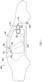
- FIG. 1 is a schematic view of an example noise-cancellation system 100.
- Noise-cancellation system 100 can be configured to destructively interfere with undesired sound in at least one cancellation zone 102 within a predefined volume 104 such as a vehicle cabin.
- a predefined volume 104 such as a vehicle cabin.
- an example of noise-cancellation system 100 can include a reference sensor 106, an error sensor 108, an actuator 110, and a controller 112.
- reference sensor 106 is configured to generate noise signal(s) 114 representative of the undesired sound, or a source of the undesired sound, within predefined volume 104.
- reference sensor 106 can be an accelerometer, or a plurality of accelerometers, mounted to and configured to detect vibrations transmitted through a vehicle structure 116. Vibrations transmitted through the vehicle structure 116 are transduced by the structure into undesired sound in the vehicle cabin (perceived as road noise), thus an accelerometer mounted to the structure provides a signal representative of the undesired sound.
- Actuator 110 can, for example, be speakers distributed in discrete locations about the perimeter of the predefined volume.
- four or more speakers can be disposed within a vehicle cabin, each of the four speakers being located within a respective door of the vehicle and configured to project sound into the vehicle cabin.
- speakers can be located within a headrest, or elsewhere in the vehicle cabin.
- a noise-cancellation signal 118 can be generated by controller 112 and provided to one or more speakers in the predefined volume, which transduce the noise-cancellation signal 118 to acoustic energy (i.e., sound waves).
- the acoustic energy produced as a result of noise-cancellation signal 118 is approximately 180° out of phase with-and thus destructively interferes with-the undesired sound within the cancellation zone 102.
- the combination of sound waves generated from the noise-cancellation signal 118 and the undesired noise in the predefined volume results in cancellation of the undesired noise, as perceived by a listener in a cancellation zone.
- noise-cancellation system 100 is configured to create the greatest noise-cancellation within one or more predefined cancellation zones 102 with the predefined volume.
- the noise-cancellation within the cancellation zones can effect a reduction in undesired sound by approximately 3 dB or more (although in varying examples, different amounts of noise-cancellation can occur).
- the noise-cancellation can cancel sounds in a range of frequencies, such as frequencies less than approximately 350 Hz (although other ranges are possible).
- Error sensor 108 disposed within the predefined volume, generates an error sensor signal 120 based on detection of residual noise resulting from the combination of the sound waves generated from the noise-cancellation signal 118 and the undesired sound in the cancellation zone.
- the error sensor signal 120 is provided to controller 112 as feedback, error sensor signal 120 representing residual noise uncanceled by the noise-cancellation signal.
- Error sensors 108 can be, for example, at least one microphone mounted within a vehicle cabin (e.g., in the roof, headrests, pillars, or elsewhere within the cabin).
- the cancellation zone(s) can be positioned remotely from error sensor 108.
- the error sensor signal 120 can be filtered to represent an estimate of the residual noise in the cancellation zone(s).
- the error signal will be understood to represent residual undesired noise in the cancellation zone.
- controller 112 can comprise a nontransitory storage medium 122 and processor 124.
- non-transitory storage medium 122 can store program code that, when executed by processor 124, implements the various filters and algorithms described below.
- Controller 112 can be implemented in hardware and/or software.
- the controller can be implemented by a SHARC floating-point DSP processor, but it should be understood that controller 112 can be implemented by any other processor, FPGA, ASIC, or other suitable hardware.
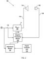
- FIG. 2 there is shown a block diagram of an example of noise-cancellation system 100, including a plurality of filters implemented by controller 112. As shown, the controller can define a control system including W adapt filter 126 and an adaptive processing module 128.
- W adapt filter 126 is configured to receive the noise signal 114 of reference sensor 106 and to generate noise-cancellation signal 118.
- Noise-cancellation signal 118 is input to actuator 110 where it is transduced into the noise-cancellation audio signal that destructively interferes with the undesired sound in the predefined cancellation zone 102.
- W adapt filter 126 can be implemented as any suitable linear filter, such as a multi-input multi-output (MIMO) finite impulse response (FIR) filter.
- MIMO multi-input multi-output
- FIR finite impulse response
- W adapt filter 126 employs a set of coefficients which define the noise-cancellation signal 118 and which can be adjusted to adapt to changing behavior of the vehicle response to road input (or to other inputs in non-vehicular noise-cancellation contexts).
- the adjustments to the coefficients can be performed by an adaptive processing module 128, which receives as inputs the error sensor signal 120 and the noise signal 114 and, using those inputs, generates a filter update signal 130.
- the filter update signal 130 is an update to the filter coefficients implemented in W adapt filter 126.
- the noise-cancellation signal 118 produced by the updated W adapt filter 126 will minimize error sensor signal 120, and, consequently, the undesired noise in the cancellation zone.
- T ⁇ de is an estimate of the physical transfer function between actuator 110 and the noise-cancellation zone 102
- T ⁇ ' de is the conjugate transpose of T ⁇ de
- e is the error signal
- x is the output signal of reference sensor 106.
- the output signal x of reference sensor is divided by the norm of x, represented as
- the total number of filters is generally equal to the number of reference sensors (M) multiplied by the number of speakers (N). Each reference sensor signal is filtered N times, and each speaker signal is then obtained as a summation of M signals (each sensor signal filtered by the corresponding filter).
- Noise-cancellation system 100 further includes an adjustment module 132 configured to vary at least one of a power of the noise-cancellation signal 118 and rate of adaptation of the adaptive filter W adapt filter 126 as implemented by the adaptive processing module 128 in response to a signal received from the reference sensor 106 or an input from the engine computer unit 134.
- the adjustment module can be implemented according to one of the various methods described in connection with FIGs. 3-8 .
- the noise-cancellation system 100 of FIGs. 1 and 2 is merely provided as an example of such a system.
- This system, variants of this system, and other suitable noise-cancellation systems can be used within the scope of this disclosure.
- the system of FIGs. 1-2 has been described in conjunction with a least-means-squares filter (LMS), in other examples a different type of filter, such as one implemented with a recursive-lease-squares (RLS) filter can be implemented.
- LMS least-means-squares filter
- RLS recursive-lease-squares
- FIGs. 3-8 depict flowcharts and associated graphs of computer-implemented methods for adjusting the output and/or adaptation of a vehicle-implemented noise-cancellation system when the SNR of the accelerometer is too low to allow to adapt the noise-cancellation system in a manner that better cancels the noise in the vehicle cabin.
- the computer-implemented methods described in connection with FIGs 3-8 can be implemented by a controller, such as a controller 112, or by any computing device suitable for carrying out the methods described in connection with FIGs. 3-8 .
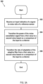
- FIG. 3A depicts a high-level flowchart of a method for adjusting the output and adaptation of the vehicle-implemented noise-cancellation system.
- Steps 302-306 generally require receiving a time-varying input representative of a signal-to-noise ratio of at least one reference sensor and transitioning the power of the noise-cancelation signal and a rate of adaptation of the noise-cancellation system from a first level to a second level (e.g., from an off state to an on state) according to a comparison of the input to a criterion.
- the criterion can be a fixed or variable threshold against which the input is compared.
- the noise-cancellation signal and/or adaptation is set to an off state. If the input is above the threshold, the noise-cancellation signal and/or adaptation are set to an on state.
- a reference sensor is any sensor generating noise signals representative of the undesired sound, or a source of the undesired sound, within a predefined volume and used to update the adaptive filter of the noise-cancellation system.
- the input indicative of the signal-to-noise ratio of at least one reference sensor can be any signal (or set of signals) which has a positive correlation with the signal-to-noise ratio of the reference sensor in a vehicular context.
- Examples of a such a signal include signals that relate to the state of a vehicle such as the speed of the vehicle, revolutions per minute of the vehicle engine, or gear position of the vehicle engine, all of which generally increase as the signal-to-noise ratio of the reference sensor(s) improves.
- These inputs of the state of the vehicle can be received from the engine computer unit (e.g., engine computer unit 134 shown in FIG. 2 ) via the CAN bus of the vehicle.
- the input indicative of the signal-to-noise ratio of at least one reference sensor can be the result of preliminary processing of the output reference sensor(s).
- the input can be a power of the noise signal output by the reference sensor(s).
- the input requires a preliminary step of finding a power of the sensor signal, such as by finding the power spectral density or average, across frequency and/or time, of a power spectral density of the sensor signal.
- any suitable method of finding the power spectral density of a reference sensor can be used.
- the combined PSD of multiple reference sensors can be defined as follows.
- N ref is the total number of reference sensors used for road noise cancellation (alternatively, a subset of reference sensors can be used)
- w j,k is the weight associated with the j th reference sensor and kth frequency bin.
- the coefficients w j,k determine which reference sensors and which frequency intervals are taken into consideration. Stated differently, the reference sensor outputs can be weighted differently and/or certain frequencies can be weighted differently according to relevance. For example, a range of frequencies of interest can be used. Road noise is typically below 400 Hz, and so, in one example, only the power below 400 Hz is used.
- This is merely provided as an example of a method of finding a PSD of a given reference sensor, as such, in alternative examples, any other suitable method for finding a PSD can be used.
- the time-varying input can be the combined (i.e., summed) PSD of a plurality of reference sensors.
- An example of the combined PSD of multiple accelerometers is shown in graph of FIG. 4A across multiple vehicle states and road surfaces including: the vehicle being in an off state, the input at zero mph, smooth pavement at 5 mph, smooth pavement at 10 mph, a gravel road at 5 mph, and a gravel road at 10 mph.
- amplitude over frequency may be used.
- the PSD can be averaged across frequencies or a range of frequencies, rendering a single power value, which can be evaluated according to the criterion.
- the power of each frequency bin of the PSD can be compared to the criterion, which will be described in connection with FIG. 3 .
- the plurality of PSDs can be averaged on a frequency-by-frequency basis. This can be shown in FIG. 4B , again for a variety of vehicle states and road surfaces including: the vehicle being in an off state, the input at zero mph, smooth pavement at 5 mph, smooth pavement at 10 mph, a gravel road at 5 mph, and a gravel road at 10 mph.
- the PSD of a single reference sensor can be used.
- the method described in connection with FIG. 3 can be repeated for each of the reference sensors, each time using a value related to the PSD of a different reference sensor. In other words, the method described in connection with FIG. 3 can be repeated for each individual reference sensor, each iteration of the method comparing the PSD of the individual sensor to a criterion.
- a value indicative of a measure of similarity between reference sensor signals can be used.
- measures of similarity include, for example, coherence or correlation between reference sensor signals. Because there is no similarity between the noise floors of the various reference sensors, the measure of similarity between sensors when the vehicle is stationary will be approximately zero. By contrast, when the vehicle is in motion, there will be some measurable similarity between the reference sensor signals because the vibrations throughout the vehicle cabin are related. Thus, the measure of similarity between the reference sensor signals will be positively correlated with the signal-to-noise ratio of the reference sensor signals because there will typically only be some similarity between the reference sensor signals when there is a signal output rather than only noise.
- the coherence is a measure of a linear relationship between the reference sensors. Because the noise output of each reference sensor is unrelated, the coherence between reference sensors when the vehicle is stationary will be approximately zero. Once the vehicle begins to move, however, and vibrations are transmitted through the vehicle chassis, the coherence between the sensors will reach some positive value because the vibrations at different points of the vehicle will be related. Theoretically, if the vibrations transmitted through the vehicle were identical, the coherence between reference sensors would equal one. However, because the wheels of the vehicle do not vibrate in the same way, and because vibrations are not transmitted through the vehicle in the same way, the coherence between reference sensors while the vehicle is moving will be some value between zero and one.
- a subset of frequencies e.g., below 400 Hz can be used.
- the correlation between two or more sensors can be used.
- coherence is more desirable because coherence is normalized; however, it should be understood that any suitable measure of similarity can be used as the input.
- the gain of the noise-cancellation signal transitions from a first value (e.g., zero) to a second value (e.g., unity), causing the power of the noise cancellation signal to transition from a first value to a second, based on a comparison of the input representative of the SNR of the reference sensor(s) to a criterion.
- the criterion can be a fixed threshold or a variable threshold.
- the power can be varied from the first value to the second value by varying the gain of the noise-cancellation signal.
- b n n G input n ⁇ b in n
- b in ( n ) the road noise cancellation signal that was generated by the adaptive filter
- the gain is set to 0 and the noise-cancellation signal is, accordingly, switched off when the value of the time-varying input (denoted as INP 1 ( n )) is less than or equal to the threshold I 1 , and the gain is set to unity and the noise-cancellation signal is sent to the speaker without attenuation when the time-varying input is above threshold I 1 .
- the power of the noise-cancellation signal is accordingly varied from zero to a second value that represents the unattenuated noise-cancellation signal.
- the gain can be set to some value that would result in a noise-cancellation signal of negligible power (i.e., one that is not perceptible to a user).
- the unattenuated noise-cancellation signal will be some value that results in the maximum allowable cancellation of the noise signal.
- the first value can be some predetermined non-zero value. Even if the noise level is too low to adapt the adaptive filter, a noise-cancellation signal can be still be played, the adaptive filter, not yet adapting, behaving like a fixed filter (having some set of predetermined or previously-stored coefficients). In this case, the first value may be some small gain value that results in the cancelling of minor road noise in the vehicle cabin during driving at low speeds over most road surfaces.
- the threshold I 1 is set to be the minimum value for which the noise-cancellation signal is generated.
- threshold I 1 would be set to some speed value for which there is road noise in the vehicle cabin (e.g., 10 mph) that can be cancelled by the noise-cancellation audio signal. It should be understood that the threshold value will be dependent on the type of input selected (e.g., vehicle speed, coherence, etc.).
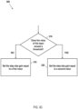
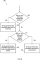
- FIG. 3B shows an example flowchart of step 304, in which the input is compared to the threshold.
- the input (described in connection with step 302) is compared to a fixed threshold (e.g., vehicle speed of ten miles per hour). This is represented by the condition block asking whether the input exceeds the threshold. If the answer to this conditional is no, at step 312, the gain of the noise-cancellation signal is set to the first value (e.g., zero or some negligible amount); whereas, if the answer to this conditional is yes the noise-cancellation signal is set, at step 314, to the second value (e.g., setting the noise-cancellation signal to unity gain).
- the first value e.g., zero or some negligible amount
- the rate of adaptation of the noise-cancellation system transitions from a first value (e.g., zero) to a second value (e.g., unity) based on the comparison of the input representative of the SNR of the reference sensor(s) to a criterion.
- this can be implemented by varying the step size gain of the update equation used by the adaptive processing module to update the adaptive filter.
- the adaptive processing module will not update the coefficients of the adaptive filter.
- the rate of adaptation set to some optimum level for updating the coefficients of the adaptive filter.
- the step size gain is zero when the input is less than or equal to the threshold I 1 and equal to unity when the input is greater than the threshold I 1 .
- the adaptive filter ceases adaptation when the input is below the threshold and begins to adapt the adaptive filter when the input is above the threshold.
- FIG. 3C shows an example flowchart of step 306 of method 300.
- the input signal is received and compared to the threshold. If the input signal (e.g., vehicle speed) is less than the threshold (e.g., 10 mph) then the step size gain is set to a first value (e.g., zero) at step 318; if, however, the signal is greater than the threshold then the step size gain is set to a second value (e.g., unity) at step 320.
- the threshold e.g. 10 mph
- FIG. 5 shows a graph of the gain of the noise-cancellation signal and step size as a function of vehicle speed (one example input). As shown, the gain is set to 0 until the vehicle speed reaches the threshold I 1 when the gain of both the noise-cancellation signal and step size are set to unity.
- the adaptation occurs concurrently with the production of the noise-cancellation signal, and so the threshold for beginning adaptation is the same as the threshold for beginning production of the noise-cancellation signal. It is not desirable to begin adaptation of the adaptive filter before the production of the noise-cancellation audio signal because the update equation relies on an error signal that presumes full operation of the noise-cancellation system. In other words, if the adaptation begins before the production of the noise-cancellation audio signal, the update equation will update as though the noise-cancellation audio signal is playing but is failing to cancel any of the undesired sound in the vehicle cabin, thus the adaptive filter will be incorrectly updated. However, in various alternative embodiments, adapting the adaptive filter could occur at some point after the start of production of the noise-cancellation signal.
- the input could be compared to a different, higher, threshold. For example, if the input is vehicle speed, the adaptation could begin at some speed higher than the speed for which the production of noise-cancellation audio signal begins. In a simpler example, the adaptation of the adaptive filter could begin some predetermined interval of time (e.g., one second) after the start of production of the noise-cancellation signal, rather than relying on a threshold.
- the adaptive filter will behave like a fixed filter.
- the coefficients of the (fixed) adaptive filter can be set to some default value of coefficients that produces road-noise cancellation for most road surfaces, or to some previously stored set of coefficients.
- a fixed threshold can fail to appropriately capture the actual SNR of the reference sensor(s) (even if the input is correlated to the SNR of the reference sensor(s)). For example, while an input of vehicle speed can accurately represent the road noise for most road conditions, it will fail to represent the road noise in rough road conditions (e.g., if the vehicle is driving over cobblestone). Thus, a second input, such as a power of the reference sensor, can be analyzed to determine the threshold for which to analyze the first input.
- the first threshold value I 1 max will be higher than the second threshold value I 1 min (here, the subscripts "max” and “min” refer to the maximum values that to which the thresholds are set, not the maximum possible and minimum possible values of the thresholds).
- the variance threshold I var 1 can be set so that, on paved road surfaces, the power of the reference sensor is insufficient to move the first threshold to a lower value I 1 min , but can be set so that in rough road conditions the second input INP 2 ( n ) will exceed the variance threshold I var 1 and accordingly set the first threshold to the second threshold value I 1 min .
- the first input INP 1 ( n ) will be compared to the first threshold value I 1 max
- the first input INP 1 ( n ) will be compared to the second threshold value I 1 min . This compensates for instances in which the first threshold fails to adequately represent the signal-to-noise ratio of the reference sensor. Because the second input is a different type of input than the first input, the second threshold will typically be different from the first threshold.
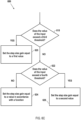
- FIG. 3D depicts a flowchart of method 322 for varying the threshold of FIGs. 3B and 3C to accommodate for varying road conditions.
- the method 322 described in connection with FIG. 3D is run before the steps of comparing the first input to the first threshold; however, as the method described in connection with FIGs. 3B and 3C is typically looped over multiple samples, the steps of FIG. 3D can be run after the steps of FIGs. 3B and 3C .
- a second input is received.
- This input can be one of the inputs described in connection with FIG. 3A step 302, however it must be a different type of input than the input compared against the threshold in steps 304 and/or 306. For example, if vehicle speed is used for step 304, then, for example, the power of the reference sensor(s) signal(s) or measure of similarity between the reference sensors signals can be used for the second input.
- the second input is compared against the variance threshold at the conditional block 326. If the second input is below the variance threshold, then the threshold is maintained at a first threshold value at step 328. If, however, the second input is above the variance threshold, the first threshold is set to a second threshold value at step 330.
- the second threshold value is typically less than the first threshold value, because the higher value of the second input is indicative of a secondary condition (e.g., rough road conditions) that could be adding noise to the vehicle cabin.
- the above-described methods account for situations in which the SNR of the reference sensor is too low to update the adaptive filter. However, abruptly turning on the noise-cancellation signal can be noticeable and jarring to a user. Accordingly, a method for smoothly transitioning the noise-cancelation signal and/or the rate of adaptation from a first value (e.g., an off state) to a second value (e.g., an on state) is described in connection with FIG. 6A .
- a first value e.g., an off state
- a second value e.g., an on state
- an input indicative of a SNR of at least one reference sensor is received.
- the input can be any input which correlates to the signal-to-noise ratio of at least one reference sensor. Examples of such inputs are described in connection with step 302.
- the power of the noise-cancellation signal smoothly transitions from the first value (e.g., zero) to the second value (e.g., unity gain) based on a comparison of the input representative of the reference sensor(s) to a criterion.
- Smoothly transitioning requires passing through at least one intermediate value between the first value and the second value, although it is contemplated that the power of the noise-cancellation signal could transition through multiple intermediate values on its way from the first value to the second value.
- the value of the intermediate value can fixed or can be determined by a function.
- the power can be varied from the first value to the second value by varying the gain of the noise-cancellation signal.
- b n G input n ⁇ b in n
- b in ( n ) the road noise cancellation signal that was generated by the adaptive filter
- the gain is thus set to 0, and the noise-cancellation signal is, accordingly, switched off (or, alternatively, set to some negligible value or some other predetermined value) when the value of the time-varying input INP 1 ( n ) is below or equal to the first threshold value I 1 and is set to unity when time-varying input is above a second threshold I 2 .
- the noise-cancellation signal gain is defined by an equation that linearly varies the between the first value and the second value.
- the gain varies linearly between the first value and the second value, smoothly transitioning the noise-cancellation signal from an off state to an on state.
- the intermediate value can be a fixed value.
- the intermediate value can be some fixed value (e.g., 0.5 gain) between the first value and the second value.
- a different function such as a logarithmic function, can define the intermediate values.
- FIG. 6B depicts an example flowchart of step 604, in which the input is compared to at least two thresholds and set to some intermediate value when between the two thresholds.
- the input (examples of which are described in connection with step 302) is compared to the first threshold (e.g., vehicle speed of ten miles per hour). This is represented by the conditional block 608 asking whether the input exceeds the first threshold. If the value of the input is less than the first threshold, the noise-cancelation signal is set to the first value at step 610.
- the first value can be zero or some negligible value (i.e., one that would result in the playing of a noise-cancellation audio signal that would be imperceptible to a user).
- the first value can be some predetermined non-zero value.
- the adaptive filter not yet adapting, behaving like a fixed filter (having some set of predetermined or previously-stored coefficients).
- the first value may be some small gain value that results in the cancelling of minor road noise in the vehicle cabin during driving at low speeds over most road surfaces.
- the input is compared to the second threshold value at step 612. This is represented by the conditional block 612 asking whether the input exceeds the second threshold. If the input is above the second threshold, the gain of noise-cancellation signal is set to the second value (e.g., unity) at step 616, which results in the noise-cancellation audio signal being played at a level that results in optimum cancellation. However, if the noise-cancellation signal is below the second threshold, then the gain of the noise-cancellation signal is set to some value in accordance with the predetermined function (e.g., the linear function disclosed in Eq.(11) or a logarithmic function) at step 614. As described above, in an alternative example, the intermediate value can be a predetermined value (e.g., a gain value of 0.5).
- the predetermined function e.g., the linear function disclosed in Eq.(11) or a logarithmic function
- the rate of adaptation can also be made to smoothly transition from a first value (e.g., zero) to a second value (e.g., unity) based on the comparison of the input representative of the SNR of the reference sensor(s) to a criterion).
- this can be implemented by varying the step size gain of the update equation used by the adaptive processing module to update the adaptive filter.
- the step size gain is zero, the adaptive processing module will not update the coefficients of the adaptive filter.
- the rate of adaptation is typically set to some optimum level for updating the coefficients of the adaptive filter.
- smoothly transitioning requires passing through at least one intermediate value between the first value and the second value, although it is contemplated that rate of adaptation could transition through multiple intermediate values on its way from the first value to the second value.
- the value of the intermediate value can be fixed or can be determined by a function.
- the step size gain is set to zero (causing adaptation to cease) while the input is less than or equal to the third threshold value.
- the step size gain is set to unity when the input is greater than the fourth threshold value.
- the step size gain is determined by the linear function shown in Eq.(13). Accordingly, the step size linearly ramps from the first value to the second value as the input value increases.
- the intermediate value could be determined by a different function, such as a logarithmic function.
- the intermediate value could be a fixed value (e.g,. 0.5).
- the third threshold is equal to or higher than the second threshold used in step 612 (and described in Eq. 11) in order to ensure that the noise-cancellation audio signal is played at optimal volume before adaptation of the adaptive filter begins. This ensures that the adaptive filter is not updated with an incorrect error signal.
- the third threshold could be set to some value lower than second threshold, if some compensation for the incorrect error signal is provided. For example, the error signal could be minimized by some gain value less than one, the error signal gain value being determined by the value of the gain of the noise-cancellation signal.
- FIG. 6C shows a flowchart of an example implementation of step 616.
- the input (examples of which are described in connection with step 302) is compared to the first threshold (e.g., vehicle speed of 20 miles per hour). This is represented by the conditional block 618 asking whether the input exceeds the third threshold. If the value of the input is less than the third threshold, the step size gain is set to the first value by adjusting the gain of the rate of adaptation at step 620.
- the first threshold e.g., vehicle speed of 20 miles per hour
- the input is compared to the fourth threshold value. This is represented by the conditional block 622 asking whether the input exceeds the fourth threshold. If the input is above the fourth threshold, then, at step 626, the step size is set to the second value (e.g., an optimum step size) by adjusting the gain to a second value (e.g., unity). However, if the input is below the second threshold, then at step 624, the gain of the step size is set to some value in accordance with the predetermined function (e.g., the linear function disclosed in Eq.(13) or a logarithmic function). In an alternative example, the intermediate value can be a predetermined value (e.g., a gain value of 0.5).
- the predetermined function e.g., the linear function disclosed in Eq.(13) or a logarithmic function.
- the intermediate value can be a predetermined value (e.g., a gain value of 0.5).
- FIG. 6B and 6C each show a single instance of a computer-implemented method that would be run in a loop in order to effect a smooth transition of the noise-cancellation signal and the rate of adaptation, respectively. Indeed, in order to transition from a first value, to a second value through an intermediate value, the method of FIGs. 6B and 6C would need to be run a minimum of three times in a loop to set the gain to a first value, an intermediate value, and a second value, respectively.
- FIG. 7 depicts a graph of the gain of the noise-cancellation signal and the step size according to Eqs. (11) and (13) versus an input of vehicle speed.
- the gain of the noise-cancellation signal linearly increases until the second threshold I 2 .
- the gain of the step size linearly increases until the fourth threshold I 4 .
- the third threshold is typically higher than or equal to the second threshold.
- the gain of the noise-cancellation output signal or the step size of the adaptive filter can follow a predetermined sequence to transition from the first value to the second value. For example, once the input exceeds a certain threshold the noise-cancellation system can begin a predetermined sequence that smoothly transitions from the first value to the second through at least one predetermined intermediate value, based on the single instance of exceeding the threshold.
- the values of the predetermined sequence can follow a predetermined function such as a linear function or a logarithmic function.
- This example can be useful for inputs that have large discrete jumps in value rather than a continuous output or small steps in value.
- the input is gear position, which typically only has five or six values
- the vehicle being in a certain gear e.g., second gear
- a smooth transition function e.g., Eq. (11) or Eq. (13)
- the noise-cancellation system can be programmed to transition the noise-cancellation signal and/or the rate of adaptation from the first value to the second value, through at least one intermediate value, without waiting for an additional gear change.
- This can follow the line of the graph shown in FIG. 7 , but only be triggered, e.g., by a single threshold.
- This example is, however, not limited to inputs with large discrete jumps and can be used for any type of input indicative of the signal-to-noise ratio of the reference sensor(s).
- the thresholds for the smooth transition described in connection with FIGs. 6A-6C can be smoothly transitioned between threshold values.
- the threshold values can be transitioned from a first threshold value to a second threshold value to compensate for certain instances in which an input (e.g., vehicle speed) fails to adequately capture the SNR of the reference sensor(s).
- the thresholds can be smoothly transitioned from the first threshold value to the second threshold value.
- the threshold values can be transitioned between the first value and the second value through at least one intermediate value.
- the given threshold when the second input is below the first variance threshold I var 1 , the given threshold is set to its maximum threshold value I i max . When the second input is above the second variance threshold I var 2 , the given threshold is set to its minimum threshold value I i min . And when the second input is between the first and second variance thresholds, the given threshold is determined by a function that linearly varies, depending on the value of the second input, between the maximum threshold value I i max and the minimum threshold value I i min . In this way, the threshold against which the first input is compared can smoothly vary from a maximum value to a minimum value.
- the second input is not the same type of input as the first input.
- the second input can be another type of input, such as power of the reference sensor(s) or a coherence of the reference sensors.
- the variance thresholds e.g., I var 1 , I var 2
- the variance thresholds can varied for each different threshold I 1 - I 4 or can be the same for each threshold I 1 - I 4 .
- FIG. 8 depicts a graph of Eq. (14), in which the first input is vehicle speed and the second input is the power of the reference sensor(s). As shown, while the PSD is less than the first variance threshold I var 1 the first threshold is held to I i max before linearly transitioning, based on the power of the reference sensor, to the I i max at the second variance threshold I var 2 .
- the function that determines the intermediate value need not be determined by a linear function but can be logarithmic or any other suitable function.
- the intermediate value can be a constant value between the maximum value and the minimum value (e.g., halfway between the maximum value and the minimum value).
- the smooth transition need not be dictated by a piecewise equation can be preprogrammed to smoothly transition over a period of time when the second input exceeds the first value.
- multiple inputs can be used to determine when to transition the noise-cancellation signal or the rate of adaptation or the thresholds used to determine when the transition occurs.
- Multiple inputs can be used by combining inputs using a logical AND or OR function. For example, rather than using a vehicle speed, a certain gear position AND the engine RPMs above a given threshold can be used to determine what value to set the noise-cancellation signal, the rate of adaptation, or a particular threshold for transition.
- a logical OR function can be used.
- the first threshold can be a certain vehicle speed OR a certain engine RPM value.
- any instance of an equation being used to determine a value can be implemented as a look-up table, the values of which are dictated by the equation, or can be calculated in real time.
- the functionality described herein, or portions thereof, and its various modifications can be implemented, at least in part, via a computer program product, e.g., a computer program tangibly embodied in an information carrier, such as one or more non-transitory machine-readable media or storage device, for execution by, or to control the operation of, one or more data processing apparatus, e.g., a programmable processor, a computer, multiple computers, and/or programmable logic components.
- a computer program product e.g., a computer program tangibly embodied in an information carrier, such as one or more non-transitory machine-readable media or storage device, for execution by, or to control the operation of, one or more data processing apparatus, e.g., a programmable processor, a computer, multiple computers, and/or programmable logic components.
- a computer program can be written in any form of programming language, including compiled or interpreted languages, and it can be deployed in any form, including as a stand-alone program or as a module, component, subroutine, or other unit suitable for use in a computing environment.
- a computer program can be deployed to be executed on one computer or on multiple computers at one site or distributed across multiple sites and interconnected by a network.
- Actions associated with implementing all or part of the functions can be performed by one or more programmable processors executing one or more computer programs to perform the functions of the calibration process. All or part of the functions can be implemented as, special purpose logic circuitry, e.g., an FPGA and/or an ASIC (application-specific integrated circuit).
- special purpose logic circuitry e.g., an FPGA and/or an ASIC (application-specific integrated circuit).
- processors suitable for the execution of a computer program include, by way of example, both general and special purpose microprocessors, and any one or more processors of any kind of digital computer.
- a processor will receive instructions and data from a read-only memory or a random access memory or both.
- Components of a computer include a processor for executing instructions and one or more memory devices for storing instructions and data.
Landscapes
- Physics & Mathematics (AREA)
- Engineering & Computer Science (AREA)
- Acoustics & Sound (AREA)
- Multimedia (AREA)
- Soundproofing, Sound Blocking, And Sound Damping (AREA)
- Fittings On The Vehicle Exterior For Carrying Loads, And Devices For Holding Or Mounting Articles (AREA)
Claims (15)
- Système d'annulation de bruit mis en œuvre dans un véhicule, comprenant :un système d'annulation de bruit (100) disposé dans un véhicule, le système d'annulation de bruit comprenant un filtre adaptatif (126) qui est réglé conformément à un signal de référence (114) et à un signal d'erreur (120), le filtre adaptatif émettant un signal d'annulation de bruit (118) qui, lorsqu'il est traduit en signal audio d'annulation de bruit par un haut-parleur (110), annule le bruit de la route dans au moins une zone (102) dans un habitacle du véhicule ; caractérisé en ce que le système d'annulation de bruit comprend en outreun module de réglage (132) configuré pour faire varier un ou les deux parmi une puissance du signal d'annulation de bruit et un rythme d'adaptation du filtre adaptatif d'une première valeur à une seconde valeur, en passant par au moins une valeur intermédiaire entre la première valeur et la seconde valeur, dans lequel la variation d'un ou des deux parmi une puissance du signal d'annulation de bruit et un rythme d'adaptation du filtre adaptatif est basée sur une comparaison d'un signal variant dans le temps indiquant un rapport signal sur bruit du signal de référence avec un premier critère.
- Système d'annulation de bruit mis en œuvre dans un véhicule selon la revendication 1, dans lequel le signal variant dans le temps est au moins un parmi : une vitesse du véhicule, une puissance du signal de référence, des tours par minute d'un moteur du véhicule, une position de rapport d'un moteur du véhicule et une mesure de similarité entre les sorties d'au moins deux des signaux de capteur de référence.
- Système d'annulation de bruit mis en œuvre dans un véhicule selon la revendication 1, dans lequel le premier critère est au moins un seuil fixe.
- Système d'annulation de bruit mis en œuvre dans un véhicule selon la revendication 1, dans lequel le premier critère est au moins un seuil variable, la variation de l'au moins un seuil variable étant basée sur un second signal variant dans le temps indiquant le rapport signal sur bruit du signal de référence.
- Système d'annulation de bruit mis en œuvre dans un véhicule selon la revendication 1, dans lequel la valeur intermédiaire est déterminée conformément à une fonction prédéterminée du signal variant dans le temps.
- Système d'annulation de bruit mis en œuvre dans un véhicule selon la revendication 5, dans lequel la fonction prédéterminée est une fonction linéaire.
- Système d'annulation de bruit mis en œuvre dans un véhicule selon la revendication 5, dans lequel la fonction prédéterminée est une fonction logarithmique.
- Système d'annulation de bruit mis en œuvre dans un véhicule selon l'une quelconque des revendications précédentes, dans lequel le module de réglage (132) est configuré pour faire varier le rythme d'adaptation du filtre adaptatif de la première valeur à la seconde valeur, en passant par l'au moins une valeur intermédiaire entre la première valeur et la seconde valeur, sur la base d'une comparaison du signal variant dans le temps indiquant un rapport signal sur bruit du signal de référence avec le premier critère.
- Procédé mis en œuvre par ordinateur pour la transition en douceur d'un système d'annulation de bruit mis en œuvre dans un véhicule d'un état éteint à un état allumé, comprenant :la réception (602) d'une entrée indiquant un rapport signal sur bruit d'un capteur de référence (106) du système d'annulation de bruit (100) ;la comparaison d'une valeur du signal avec un premier seuil (608 ; 618), dans lequel si une valeur du signal est inférieure au premier seuil, un ou les deux parmi une puissance d'un signal d'annulation de bruit et un rythme d'adaptation du système d'annulation de bruit sont fixés sur une première valeur, dans lequel si la valeur du signal est supérieure au premier seuil, le procédé est caractérisé par la réalisation de l'étape consistant à :
comparer la valeur du signal à un deuxième seuil (612 ; 622), dans lequel si la valeur du signal est supérieure au deuxième seuil, l'un ou les deux parmi la puissance de l'annulation de bruit et le rythme d'adaptation sont fixés sur une deuxième valeur, dans lequel si le signal est supérieur au premier seuil et inférieur au deuxième seuil, l'un ou les deux parmi la puissance d'un signal d'annulation de bruit et le rythme d'adaptation sont fixés sur une valeur intermédiaire, dans lequel le deuxième seuil est supérieur au premier seuil. - Procédé mis en œuvre par ordinateur selon la revendication 9, dans lequel l'entrée est au moins un parmi : une vitesse du véhicule, une puissance du signal de référence, des tours par minute d'un moteur du véhicule, une position de rapport d'un moteur du véhicule et une mesure de similarité entre les sorties d'au moins deux capteurs de référence.
- Procédé mis en œuvre par ordinateur selon la revendication 9, dans lequel la valeur de la valeur intermédiaire est déterminée conformément à une fonction prédéterminée de l'entrée.
- Procédé mis en œuvre par ordinateur selon la revendication 11, dans lequel la fonction prédéterminée est une fonction linéaire.
- Procédé mis en œuvre par ordinateur selon la revendication 11, dans lequel la fonction prédéterminée est une fonction logarithmique.
- Procédé mis en œuvre par ordinateur selon la revendication 9, dans lequel la valeur du premier seuil et du deuxième seuil est déterminée conformément à un second signal indiquant un rapport signal sur bruit du capteur de référence.
- Procédé mis en œuvre par ordinateur selon la revendication 9, comprenant en outre les étapes consistant à :recevoir une seconde entrée indiquant un rapport signal sur bruit du capteur de référence ;comparer une valeur du second signal à un troisième seuil, dans lequel si une valeur du signal est inférieure au troisième seuil, le premier seuil est fixé sur une première valeur de seuil, dans lequel si la valeur du second signal est supérieure au troisième seuil, réaliser l'étape consistant à :
comparer la valeur du second signal à un quatrième seuil, dans lequel si la valeur du second signal est supérieure au quatrième seuil, le premier seuil est fixé sur une seconde valeur de seuil, dans lequel si le second signal est supérieur au troisième seuil et inférieur au quatrième seuil, le premier seuil est fixé sur une valeur intermédiaire, dans lequel le deuxième seuil est supérieur au premier seuil.
Applications Claiming Priority (2)
| Application Number | Priority Date | Filing Date | Title |
|---|---|---|---|
| US16/782,676 US11380298B2 (en) | 2020-02-05 | 2020-02-05 | Systems and methods for transitioning a noise-cancellation system |
| PCT/US2021/015078 WO2021158393A1 (fr) | 2020-02-05 | 2021-01-26 | Systèmes et procédés de transition d'un système d'annulation de bruit |
Publications (2)
| Publication Number | Publication Date |
|---|---|
| EP4100945A1 EP4100945A1 (fr) | 2022-12-14 |
| EP4100945B1 true EP4100945B1 (fr) | 2025-06-04 |
Family
ID=74595473
Family Applications (1)
| Application Number | Title | Priority Date | Filing Date |
|---|---|---|---|
| EP21705402.2A Active EP4100945B1 (fr) | 2020-02-05 | 2021-01-26 | Systèmes et procédés de transition d'un système d'annulation de bruit |
Country Status (4)
| Country | Link |
|---|---|
| US (1) | US11380298B2 (fr) |
| EP (1) | EP4100945B1 (fr) |
| CN (1) | CN115210806B (fr) |
| WO (1) | WO2021158393A1 (fr) |
Families Citing this family (3)
| Publication number | Priority date | Publication date | Assignee | Title |
|---|---|---|---|---|
| US11232779B1 (en) * | 2020-10-09 | 2022-01-25 | Harman International Industries, Incorporated | System and method for intelligent adjustment for filter(s) for road noise cancellation |
| CN118680535B (zh) * | 2024-05-20 | 2025-02-28 | 苏州大学 | 一种血压测量方法、系统、设备和介质 |
| CN118509772A (zh) * | 2024-07-11 | 2024-08-16 | 方博科技(深圳)有限公司 | 渐进式滤波器参数调整的Chirp信号均衡优化方法 |
Citations (1)
| Publication number | Priority date | Publication date | Assignee | Title |
|---|---|---|---|---|
| US20170076709A1 (en) * | 2015-09-16 | 2017-03-16 | Bose Corporation | Estimating secondary path magnitude in active noise control |
Family Cites Families (10)
| Publication number | Priority date | Publication date | Assignee | Title |
|---|---|---|---|---|
| JPH06332470A (ja) * | 1993-05-21 | 1994-12-02 | Fuji Heavy Ind Ltd | 車室内騒音低減装置 |
| JPH09218687A (ja) | 1996-02-14 | 1997-08-19 | Shinko Electric Co Ltd | 消音装置 |
| US8306240B2 (en) | 2008-10-20 | 2012-11-06 | Bose Corporation | Active noise reduction adaptive filter adaptation rate adjusting |
| JP2011121534A (ja) | 2009-12-14 | 2011-06-23 | Honda Motor Co Ltd | 能動型騒音制御装置 |
| CN103607982B (zh) * | 2011-05-11 | 2016-10-12 | 塞伦蒂姆公司 | 噪声控制的装置、系统和方法 |
| US9076431B2 (en) * | 2011-06-03 | 2015-07-07 | Cirrus Logic, Inc. | Filter architecture for an adaptive noise canceler in a personal audio device |
| WO2014115533A1 (fr) | 2013-01-28 | 2014-07-31 | パナソニック株式会社 | Dispositif de réduction active du bruit, instrument utilisant celui-ci et procédé de réduction active du bruit |
| KR101628119B1 (ko) * | 2014-08-11 | 2016-06-08 | 현대자동차 주식회사 | 소음제어시스템 및 그 방법 |
| US9928823B2 (en) * | 2016-08-12 | 2018-03-27 | Bose Corporation | Adaptive transducer calibration for fixed feedforward noise attenuation systems |
| US9870763B1 (en) | 2016-11-23 | 2018-01-16 | Harman International Industries, Incorporated | Coherence based dynamic stability control system |
-
2020
- 2020-02-05 US US16/782,676 patent/US11380298B2/en active Active
-
2021
- 2021-01-26 EP EP21705402.2A patent/EP4100945B1/fr active Active
- 2021-01-26 CN CN202180017755.0A patent/CN115210806B/zh active Active
- 2021-01-26 WO PCT/US2021/015078 patent/WO2021158393A1/fr not_active Ceased
Patent Citations (1)
| Publication number | Priority date | Publication date | Assignee | Title |
|---|---|---|---|---|
| US20170076709A1 (en) * | 2015-09-16 | 2017-03-16 | Bose Corporation | Estimating secondary path magnitude in active noise control |
Also Published As
| Publication number | Publication date |
|---|---|
| WO2021158393A1 (fr) | 2021-08-12 |
| CN115210806B (zh) | 2025-09-02 |
| US11380298B2 (en) | 2022-07-05 |
| US20210241748A1 (en) | 2021-08-05 |
| EP4100945A1 (fr) | 2022-12-14 |
| CN115210806A (zh) | 2022-10-18 |
Similar Documents
| Publication | Publication Date | Title |
|---|---|---|
| EP4100945B1 (fr) | Systèmes et procédés de transition d'un système d'annulation de bruit | |
| JP7612848B2 (ja) | 推定された二次経路を適応させるためのシステム及び方法 | |
| EP3844744B1 (fr) | Systèmes et procédés d'annulation de bruit à l'aide d'une projection de microphone | |
| US10121464B2 (en) | Subband algorithm with threshold for robust broadband active noise control system | |
| EP3529798B1 (fr) | Commande de bruit | |
| WO2006011380A1 (fr) | Dispositif actif reducteur de bruit | |
| EP3844741B1 (fr) | Systèmes et procédés de suppression de bruit avec filtres de mise en forme et de pondération | |
| JP7633374B2 (ja) | 適応システムにおける発散を検出するためのシステム及び方法 | |
| EP4270380A1 (fr) | Annulation rapide de bruit de microphone distant haute fréquence | |
| US11869477B2 (en) | Noise cancellation signal saturation control | |
| US10706834B2 (en) | Systems and methods for disabling adaptation in an adaptive feedforward control system | |
| JP2940248B2 (ja) | 能動型不快波制御装置 | |
| EP3994681B1 (fr) | Commande automatique de bruit | |
| JP3178865B2 (ja) | 能動型騒音制御装置 | |
| EP4428851A2 (fr) | Système et procédé pour éliminer des artéfacts d'annulation de bruit d'un mouvement de tête | |
| EP3994682B1 (fr) | Commande automatique de bruit | |
| JPH06314097A (ja) | 能動型騒音制御装置 | |
| JPH06130970A (ja) | 能動型騒音制御装置 | |
| WO2026024436A1 (fr) | Estimateur de signal de microphone auriculaire et/ou générateur de filtre de projection pour système d'annulation de bruit de route (rnc) | |
| JPH0527775A (ja) | 能動型騒音制御装置 |
Legal Events
| Date | Code | Title | Description |
|---|---|---|---|
| STAA | Information on the status of an ep patent application or granted ep patent |
Free format text: STATUS: UNKNOWN |
|
| STAA | Information on the status of an ep patent application or granted ep patent |
Free format text: STATUS: THE INTERNATIONAL PUBLICATION HAS BEEN MADE |
|
| PUAI | Public reference made under article 153(3) epc to a published international application that has entered the european phase |
Free format text: ORIGINAL CODE: 0009012 |
|
| STAA | Information on the status of an ep patent application or granted ep patent |
Free format text: STATUS: REQUEST FOR EXAMINATION WAS MADE |
|
| 17P | Request for examination filed |
Effective date: 20220726 |
|
| AK | Designated contracting states |
Kind code of ref document: A1 Designated state(s): AL AT BE BG CH CY CZ DE DK EE ES FI FR GB GR HR HU IE IS IT LI LT LU LV MC MK MT NL NO PL PT RO RS SE SI SK SM TR |
|
| DAV | Request for validation of the european patent (deleted) | ||
| DAX | Request for extension of the european patent (deleted) | ||
| STAA | Information on the status of an ep patent application or granted ep patent |
Free format text: STATUS: EXAMINATION IS IN PROGRESS |
|
| 17Q | First examination report despatched |
Effective date: 20240313 |
|
| GRAP | Despatch of communication of intention to grant a patent |
Free format text: ORIGINAL CODE: EPIDOSNIGR1 |
|
| STAA | Information on the status of an ep patent application or granted ep patent |
Free format text: STATUS: GRANT OF PATENT IS INTENDED |
|
| INTG | Intention to grant announced |
Effective date: 20250220 |
|
| GRAS | Grant fee paid |
Free format text: ORIGINAL CODE: EPIDOSNIGR3 |
|
| GRAA | (expected) grant |
Free format text: ORIGINAL CODE: 0009210 |
|
| STAA | Information on the status of an ep patent application or granted ep patent |
Free format text: STATUS: THE PATENT HAS BEEN GRANTED |
|
| AK | Designated contracting states |
Kind code of ref document: B1 Designated state(s): AL AT BE BG CH CY CZ DE DK EE ES FI FR GB GR HR HU IE IS IT LI LT LU LV MC MK MT NL NO PL PT RO RS SE SI SK SM TR |
|
| REG | Reference to a national code |
Ref country code: GB Ref legal event code: FG4D |
|
| REG | Reference to a national code |
Ref country code: CH Ref legal event code: EP |
|
| REG | Reference to a national code |
Ref country code: DE Ref legal event code: R096 Ref document number: 602021031725 Country of ref document: DE |
|
| REG | Reference to a national code |
Ref country code: IE Ref legal event code: FG4D |
|
| REG | Reference to a national code |
Ref country code: NL Ref legal event code: MP Effective date: 20250604 |
|
| PG25 | Lapsed in a contracting state [announced via postgrant information from national office to epo] |
Ref country code: FI Free format text: LAPSE BECAUSE OF FAILURE TO SUBMIT A TRANSLATION OF THE DESCRIPTION OR TO PAY THE FEE WITHIN THE PRESCRIBED TIME-LIMIT Effective date: 20250604 Ref country code: ES Free format text: LAPSE BECAUSE OF FAILURE TO SUBMIT A TRANSLATION OF THE DESCRIPTION OR TO PAY THE FEE WITHIN THE PRESCRIBED TIME-LIMIT Effective date: 20250604 |
|
| REG | Reference to a national code |
Ref country code: LT Ref legal event code: MG9D |
|
| PG25 | Lapsed in a contracting state [announced via postgrant information from national office to epo] |
Ref country code: GR Free format text: LAPSE BECAUSE OF FAILURE TO SUBMIT A TRANSLATION OF THE DESCRIPTION OR TO PAY THE FEE WITHIN THE PRESCRIBED TIME-LIMIT Effective date: 20250905 Ref country code: NO Free format text: LAPSE BECAUSE OF FAILURE TO SUBMIT A TRANSLATION OF THE DESCRIPTION OR TO PAY THE FEE WITHIN THE PRESCRIBED TIME-LIMIT Effective date: 20250904 |
|
| PG25 | Lapsed in a contracting state [announced via postgrant information from national office to epo] |
Ref country code: PL Free format text: LAPSE BECAUSE OF FAILURE TO SUBMIT A TRANSLATION OF THE DESCRIPTION OR TO PAY THE FEE WITHIN THE PRESCRIBED TIME-LIMIT Effective date: 20250604 |
|
| PG25 | Lapsed in a contracting state [announced via postgrant information from national office to epo] |
Ref country code: BG Free format text: LAPSE BECAUSE OF FAILURE TO SUBMIT A TRANSLATION OF THE DESCRIPTION OR TO PAY THE FEE WITHIN THE PRESCRIBED TIME-LIMIT Effective date: 20250604 |
|
| PG25 | Lapsed in a contracting state [announced via postgrant information from national office to epo] |
Ref country code: HR Free format text: LAPSE BECAUSE OF FAILURE TO SUBMIT A TRANSLATION OF THE DESCRIPTION OR TO PAY THE FEE WITHIN THE PRESCRIBED TIME-LIMIT Effective date: 20250604 |
|
| PG25 | Lapsed in a contracting state [announced via postgrant information from national office to epo] |
Ref country code: RS Free format text: LAPSE BECAUSE OF FAILURE TO SUBMIT A TRANSLATION OF THE DESCRIPTION OR TO PAY THE FEE WITHIN THE PRESCRIBED TIME-LIMIT Effective date: 20250904 |
|
| PG25 | Lapsed in a contracting state [announced via postgrant information from national office to epo] |
Ref country code: LV Free format text: LAPSE BECAUSE OF FAILURE TO SUBMIT A TRANSLATION OF THE DESCRIPTION OR TO PAY THE FEE WITHIN THE PRESCRIBED TIME-LIMIT Effective date: 20250604 |
|
| PG25 | Lapsed in a contracting state [announced via postgrant information from national office to epo] |
Ref country code: NL Free format text: LAPSE BECAUSE OF FAILURE TO SUBMIT A TRANSLATION OF THE DESCRIPTION OR TO PAY THE FEE WITHIN THE PRESCRIBED TIME-LIMIT Effective date: 20250604 |
|
| PG25 | Lapsed in a contracting state [announced via postgrant information from national office to epo] |
Ref country code: PT Free format text: LAPSE BECAUSE OF FAILURE TO SUBMIT A TRANSLATION OF THE DESCRIPTION OR TO PAY THE FEE WITHIN THE PRESCRIBED TIME-LIMIT Effective date: 20251006 |
|
| REG | Reference to a national code |
Ref country code: AT Ref legal event code: MK05 Ref document number: 1801168 Country of ref document: AT Kind code of ref document: T Effective date: 20250604 |
|
| PG25 | Lapsed in a contracting state [announced via postgrant information from national office to epo] |
Ref country code: IS Free format text: LAPSE BECAUSE OF FAILURE TO SUBMIT A TRANSLATION OF THE DESCRIPTION OR TO PAY THE FEE WITHIN THE PRESCRIBED TIME-LIMIT Effective date: 20251004 |
|
| PGFP | Annual fee paid to national office [announced via postgrant information from national office to epo] |
Ref country code: GB Payment date: 20251219 Year of fee payment: 6 |
|
| PG25 | Lapsed in a contracting state [announced via postgrant information from national office to epo] |
Ref country code: AT Free format text: LAPSE BECAUSE OF FAILURE TO SUBMIT A TRANSLATION OF THE DESCRIPTION OR TO PAY THE FEE WITHIN THE PRESCRIBED TIME-LIMIT Effective date: 20250604 Ref country code: SM Free format text: LAPSE BECAUSE OF FAILURE TO SUBMIT A TRANSLATION OF THE DESCRIPTION OR TO PAY THE FEE WITHIN THE PRESCRIBED TIME-LIMIT Effective date: 20250604 |
|
| PGFP | Annual fee paid to national office [announced via postgrant information from national office to epo] |
Ref country code: FR Payment date: 20251217 Year of fee payment: 6 |
|
| PG25 | Lapsed in a contracting state [announced via postgrant information from national office to epo] |
Ref country code: CZ Free format text: LAPSE BECAUSE OF FAILURE TO SUBMIT A TRANSLATION OF THE DESCRIPTION OR TO PAY THE FEE WITHIN THE PRESCRIBED TIME-LIMIT Effective date: 20250604 |
|
| PG25 | Lapsed in a contracting state [announced via postgrant information from national office to epo] |
Ref country code: EE Free format text: LAPSE BECAUSE OF FAILURE TO SUBMIT A TRANSLATION OF THE DESCRIPTION OR TO PAY THE FEE WITHIN THE PRESCRIBED TIME-LIMIT Effective date: 20250604 |
|
| PG25 | Lapsed in a contracting state [announced via postgrant information from national office to epo] |
Ref country code: SK Free format text: LAPSE BECAUSE OF FAILURE TO SUBMIT A TRANSLATION OF THE DESCRIPTION OR TO PAY THE FEE WITHIN THE PRESCRIBED TIME-LIMIT Effective date: 20250604 |
|
| PG25 | Lapsed in a contracting state [announced via postgrant information from national office to epo] |
Ref country code: IT Free format text: LAPSE BECAUSE OF FAILURE TO SUBMIT A TRANSLATION OF THE DESCRIPTION OR TO PAY THE FEE WITHIN THE PRESCRIBED TIME-LIMIT Effective date: 20250604 |