EP4100680B1 - Gas-luft-mischer - Google Patents
Gas-luft-mischer Download PDFInfo
- Publication number
- EP4100680B1 EP4100680B1 EP21716244.5A EP21716244A EP4100680B1 EP 4100680 B1 EP4100680 B1 EP 4100680B1 EP 21716244 A EP21716244 A EP 21716244A EP 4100680 B1 EP4100680 B1 EP 4100680B1
- Authority
- EP
- European Patent Office
- Prior art keywords
- gas
- air
- outer body
- mixer
- ring member
- Prior art date
- Legal status (The legal status is an assumption and is not a legal conclusion. Google has not performed a legal analysis and makes no representation as to the accuracy of the status listed.)
- Active
Links
Images


Classifications
-
- F—MECHANICAL ENGINEERING; LIGHTING; HEATING; WEAPONS; BLASTING
- F23—COMBUSTION APPARATUS; COMBUSTION PROCESSES
- F23D—BURNERS
- F23D14/00—Burners for combustion of a gas, e.g. of a gas stored under pressure as a liquid
- F23D14/46—Details
- F23D14/62—Mixing devices; Mixing tubes
-
- F—MECHANICAL ENGINEERING; LIGHTING; HEATING; WEAPONS; BLASTING
- F23—COMBUSTION APPARATUS; COMBUSTION PROCESSES
- F23L—SUPPLYING AIR OR NON-COMBUSTIBLE LIQUIDS OR GASES TO COMBUSTION APPARATUS IN GENERAL ; VALVES OR DAMPERS SPECIALLY ADAPTED FOR CONTROLLING AIR SUPPLY OR DRAUGHT IN COMBUSTION APPARATUS; INDUCING DRAUGHT IN COMBUSTION APPARATUS; TOPS FOR CHIMNEYS OR VENTILATING SHAFTS; TERMINALS FOR FLUES
- F23L13/00—Construction of valves or dampers for controlling air supply or draught
- F23L13/02—Construction of valves or dampers for controlling air supply or draught pivoted about a single axis but having not other movement
-
- F—MECHANICAL ENGINEERING; LIGHTING; HEATING; WEAPONS; BLASTING
- F23—COMBUSTION APPARATUS; COMBUSTION PROCESSES
- F23D—BURNERS
- F23D2900/00—Special features of, or arrangements for burners using fluid fuels or solid fuels suspended in a carrier gas
- F23D2900/14—Special features of gas burners
- F23D2900/14021—Premixing burners with swirling or vortices creating means for fuel or air
Definitions
- the present invention relates to a modular gas-air mixer which is used to transfer gas and air to the combustion chamber upon mixing thereof.
- the combustion products (gas and air) are mixed by the fan and gas-air mixer and sent to the combustion chamber. Since the gas-air mixture formed in this way is supplied homogeneously, all or almost all of the gas burns.
- the pre-mixing fan used in gas burning devices air and gas are sucked and the gas-air mixture is blown into the burner.
- Electronically or pneumatically adjustable gas valves are used to adjust the mixing ratio.
- the gas valve provides gas flow with the effect of negative pressure and the gas is directly mixed into the sucked air.
- gas-air mixers are comprised of a chamber, an air passage channel for the passage of air through the chamber, a gas inlet opening into the chamber and a plurality of holes located on the air passage channel. While the air passes through the air channel, the gas enters the chamber. Gas mixes with air by passing through the holes on the air passage channel. Depending on the flow of the sucked air, the gas mixes at an appropriate rate and the air + gas mixture required for combustion is formed.
- the negative pressure (the vacuum effect) is obtained by means of a venturi arranged on the suction side of the fan, wherein a locally higher flow velocity and negative pressure are obtained by locally reducing the flow cross-section (Bernoulli-equation).
- the air passage channel is comprised of two conical cylindrical parts which are separate from each other and are joined afterwards, and the holes used for gas passage are located at the joints of the said two parts.
- WO2018015130A1 discloses a gas-air mixing device comprising an air inlet channel body including a narrowing section, an air outlet channel body, and which is comprised of extension openings provided on the air outlet channel body.
- the invention for the passage of the gas into the air passage channel, the invention comprises two conical cylindrical parts with different diameters in the part where they are connected to each other and the gas passes through the extension openings at the junction part of the said two parts.
- the said application cannot be used for gas burners (boilers, etc.) with different energy levels; a separate mixer must be prepared for each energy group (24 kW, 45 kW, etc.).
- the structure in the said application does not allow the modulation rate to be changed according to the demand of the device.
- the European Patent Application EP3662989A1 discloses a fluid mixer wherein a valve is arranged inside a venturi tube.
- the objective of the present invention is to provide a gas-air mixer which is modular for gas burning devices with different energy levels in which they are to be used and whose capacity can be changed without changing its interior part.
- the objective of the present invention is to provide a gas-air mixer, which enables to increase the modulation rate of the product by keeping the minimum fan speed of the device at a range in which the fan of the device can operate safely, and in which the amount of the incoming air can be changed.
- the objective of the present invention is to provide a gas-air mixer which allows the air passage to be more turbulent and therefore to increase the amount of gas in the mixture without increasing the pressure loss of the product.
- the objective of the present invention is to provide a gas-air mixer which has low pressure loss.
- the objective of the invention is to increase the modulation level with a modular structure while keeping the minimum fan speed within the safe range in which the fan can operate without increasing the maximum fan speed, and thereby preventing the high noise level caused by the high maximum fan speed.
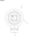
- the mixer (1) of the present invention is comprised of an outer body (2) into which gas is transferred through a gas inlet (21), an inner body (3) in the form of a cylinder which is placed inside the outer body (2) and comprises air inlet-outlet, openings (33) which are provided on the inner body (3), and the turbulator (4) or valve system (5) which is located on the air inlet of the inner body (3).
- the outer body (2) located in the mixer (1) is preferably in the form of a cylinder that is open at both ends and there is a gas inlet (21) in the form of a hole, preferably on the middle part of the outer body (2).
- the inner body (3) located in the mixer (1) comprises parts, the section of which narrows and expands, and it has an opening (33) in the form of a hole preferably where the section is narrow.
- the turbulator (4) and/or the valve system (5) makes the air which will enter into the inner body (3) more turbulent without changing the fan (which transfers the air to the inner body (3)) or by increasing its speed at a minimum level, and in this way, it enables to increase the amount of gas in the mixture without increasing the pressure loss of the product. Therefore, for gas burning devices having different energy levels (24 kW, 45 kW boiler, etc.), a single mixer (1) can be used without changing the inner body (3) and outer body (2), only by changing the valve system (5) and/or the turbulator (4). Thus, it is possible to provide the air-gas mixture of the boilers with different energy needs by changing only the turbulator (4) and/or the valve system (5) during production. In addition, this minimizes labor and mold costs, and also reduces mass production costs. Since different modulation rates can be provided easily with the modular structure, it also reduces inventory costs.
- the turbulator (4) and/or the valve system (5) are changed according to the boiler energy level after mounting of the outer body (2) and the inner body (3) in the production.
- the air first comes onto the turbulator (4) and/or the valve system (5) on the inner body (3), and the air moves in the inner body (3) upon becoming turbulent in the turbulator (4) and/or the valve system (5) and/or in a desired amount of passage.
- the gas is filled into the outer body (2) through the gas inlet (21) on the outer body (2) and the gas flows into the inner body (3) through the opening (33) according to the Bernoulli-equation (negative pressure state with high flow velocity due to narrowing section in the inner body (3)), and mixes with the air.
- the inner body (3) is comprised of air inlet channel (31) and outlet channel (32), which are a single piece, and openings (33) located at the junction of the air inlet channel (31) and the air outlet channel (32).
- the air inlet channel (31) is comprised of the flat mounting surface and the narrowing section, and the outlet channel (32) section has a conical structure with an expanding section.
- the turbulator (4) and/or the valve system (5) are placed on the flat mounting surface on the air inlet channel (31).
- the air before the air reaches the narrowing section structure, it is regulated by the turbulator (4) and/or the valve system (5), it becomes a turbulent flow and/or the amount of air passage is determined and the noise and poor quality combustion that may occur in different gases is prevented.
- the regulated flow prevents poor quality combustion caused by the gas quality.
- the air inlet channel (31) has a mounting surface (311) extending outward from the outer body (2) and when the inner body (3) is placed inside the outer body (2), the mounting surface (311) remains outside the outer body length.
- the turbulator (4) and/or the valve system (5) is fixed on the inner body (3) mounting surface (311) outside the outer body (2).
- the turbulator (4) and/or the valve system (5) can be easily detached from and attached to the inner body (3) and outer body (2).
- the minimum load and maximum load ratio which the mixer (Venturi) (1) can provide in gas burning devices is called the modulation ratio. Since the mixer (venturi) (1) provides the gas mixture, it enables the maximum possible gas ratio to be determined.
- the device has a modular venturi structure so that it can operate in different modulation ranges in different models. The said modulation range is adjusted with the turbulator (4) and/or the valve system (5).
Landscapes
- Engineering & Computer Science (AREA)
- Chemical & Material Sciences (AREA)
- Combustion & Propulsion (AREA)
- Mechanical Engineering (AREA)
- General Engineering & Computer Science (AREA)
- Gas Burners (AREA)
Claims (10)
- Ein Mischer (1), der verwendet wird, um Gas und Luft in die Verbrennungskammer in Gasverbrennungsvorrichtungen, wie z.B. Heizkesseln, nach deren Vermischung zu überführen, umfassend- mindestens einen Außenkörper (2), der mindestens einen Gaseinlass (21) für Gasüberführung in seinen inneren Teil und ein Innenvolumen aufweist,- mindestens einen Innenkörper (3), der im Inneren des Außenkörpers (2) angeordnet ist, einen Einlass für den Luftdurchtritt und einen Auslass für das Luft-Gas-Gemisch sowie mindestens eine Öffnung (33) für den Gasdurchtritt dahinein aus dem Außenkörper (2) aufweist,- mindestens einen Turbulator (4), der zur Erhöhung des Turbulenzgrades im Lufteinlass, zur Erhöhung der Modulationsrate der Vorrichtung und zur Erhöhung einer minimalen Gebläsedrehzahl der Vorrichtung durch Erhöhung der maximalen Gebläsedrehzahl, bei der die Vorrichtung in minimalem Umfang arbeiten kann, verwendet wird, und ausdadurch gekennzeichnet, dass das mindestens ein erstes Ringelement (41) an dem Lufteinlassteil des Innenkörpers (3) befestigt ist.• mindestens einem ersten Ringelement (41)• einem Mittelteil (42), das vorzugsweise auf dem mittleren Abschnitt des ersten Ringelements (41) vorgesehen ist, und• einer Vielzahl von ortsfesten Lamellen (43), die zwischen dem Mittelteil (42) und dem ersten Ringelement (41) angeordnet sind, besteht,
- Ein Mischer (1), der verwendet wird, um Gas und Luft in die Verbrennungskammer in Gasverbrennungsvorrichtungen, wie z.B. Heizkesseln, nach deren Vermischung zu überführen, umfassend- mindestens einen Außenkörper (2), der mindestens einen Gaseinlass (21) für die Gasüberführung in seinen inneren Teil und ein Innenvolumen aufweist,- mindestens einen Innenkörper (3), der im Inneren des Außenkörpers (2) angeordnet ist, einen Einlass für den Luftdurchtritt und einen Auslass für das Luft-Gas-Gemisch sowie mindestens eine Öffnung (33) für die Gasdurchtritt dahinein aus dem Außenkörper (2) aufweist, gekennzeichnet durch,- mindestens ein Ventilsystem (5), das es ermöglicht, eine minimale Gebläsedrehzahl der Vorrichtung in einem sicheren Bereich zu halten, in welchem das Gebläse arbeiten kann, indem es die maximale Gebläsedrehzahl, mit der die Vorrichtung arbeiten kann, auf ein minimales Niveau erhöht, um die Modulationsrate zu bestimmen, umfassend• ein zweites Ringelement (51), das am Lufteintrittsteil des Innenkörpers (3) befestigt ist,• mindestens einen Drehstift (52), der auf dem zweiten Ringelement (51) befestigt ist,• mindestens eine Klappe (53), die an dem Drehstift (52) befestigt ist und mit dem Drehstift (52) verstellbar ist.
- Ein Mischer (1) nach Anspruch 1 oder 2, umfassend einen Innenkörper (3), der einen Lufteinlasskanal (31) und einen Luftauslasskanal (32) umfasst, die einstückig ausgebildet sind, und Öffnungen (33), die sich an der Verbindungsstelle des Lufteinlasskanals (31) und des Luftauslasskanals (32) befinden.
- Ein Mischer (1) nach Anspruch 1 oder 2, umfassend eine Montagefläche (311) des Lufteinlasskanals (31), die sich von dem Außenkörper (2) nach außen erstreckt und außerhalb der Länge des Außenkörpers verbleibt, wenn der Innenkörper (3) in dem Außenkörper (2) angeordnet ist.
- Ein Mischer (1) nach Anspruch 1 oder 3, umfassend eine Schaufel (43), die am Mittelteil (42) in einem Winkel entsprechend der Lufteinlassrichtung befestigt ist.
- Ein Mischer (1) nach Anspruch 1 oder 2, umfassend mindestens ein Dichtungselement (6), das verhindert, dass das in den inneren Teil des Außenkörpers (2) eintretende Gas zwischen der Innenwand des Außenkörpers (2) und der Oberseite des Innenkörpers (3) entweicht (austritt).
- Ein Mischer (1) nach Anspruch 6, umfassend ein Dichtungselement (6), das eine Dichtung oder ein O-Ring ist.
- Ein Mischer (1) nach Anspruch 6, umfassend mindestens einen Schlitz (35), der mit vorspringenden Flächen an der Außenfläche des Innenkörpers (3) ausgebildet ist und in den das Dichtungselement (6) passt.
- Ein Mischer (1) nach Anspruch 1 oder 2, umfassend eine Befestigungsanordnung, die zur Befestigung des Innenkörpers am Außenkörper (2) verwendet wird und Folgendes umfasst:- mindestens ein Sperrstift in Form eines Vorsprungs, der an der Außenfläche des Innenkörpers (3) vorgesehen ist,- mindestens ein Verriegelungskanal (22), der am Endteil des Außenkörpers (2) in Form einer schrägen Kanalausnehmung am Außenkörper (2) vorgesehen ist und in den der Verriegelungsstift eingeführt werden kann.
- Ein Mischer (1), der verwendet wird, um Gas und Luft in die Verbrennungskammer in Gasverbrennungsvorrichtungen, wie z.B. Heizkesseln, nach deren Vermischung zu überführen, umfassend- mindestens einen Außenkörper (2), der mindestens einen Gaseinlass (21) für die Gasüberführung in seinen inneren Teil und ein Innenvolumen aufweist,- mindestens ein Innenkörper (3), der im Inneren des Außenkörpers (2) angeordnet ist, einen Einlass für den Luftdurchtritt und einen Auslass für das Luft-Gas- Gemisch sowie mindestens eine Öffnung (33) für den Gasdurchtritt dahinein aus dem Außenkörper (2) aufweist,- mindestens ein Turbulator (4), der dazu dient, die Luft zu verwirbeln, umfassend• ein erstes Ringelement (41), ein Mittelteil (42), das vorzugsweise auf dem mittleren Teil des ersten Ringelements (41) angeordnet ist, und eine Vielzahl von festen Lamellen (43), die zwischen dem Mittelteil (42) und dem ersten Ringelement (41) angeordnet sind, gekennzeichnet durch- mindestens ein Ventilsystem (5), das es ermöglicht, die Modulationsrate zu bestimmen und eine minimale Gebläsedrehzahl der Vorrichtung zu erhöhen, indem die maximale Gebläsedrehzahl, mit der die Vorrichtung arbeiten kann, auf ein Minimum erhöht wird, und Folgendes umfasst:• ein zweites Ringelement (51), das an dem Lufteinlassteil des Innenkörpers (3) befestigt ist, mindestens ein Drehstift (52), der an dem zweiten Ringelement (51) befestigt ist, mindestens eine Klappe (53), die an dem Drehstift (52) befestigt und mit dem Drehstift (52) verstellbar ist.
Applications Claiming Priority (2)
| Application Number | Priority Date | Filing Date | Title |
|---|---|---|---|
| TR2021/00913A TR202100913A2 (tr) | 2021-01-21 | 2021-01-21 | Bi̇r hava gaz kariştirici |
| PCT/TR2021/050155 WO2022159051A1 (en) | 2021-01-21 | 2021-02-19 | Gas-air mixer |
Publications (2)
| Publication Number | Publication Date |
|---|---|
| EP4100680A1 EP4100680A1 (de) | 2022-12-14 |
| EP4100680B1 true EP4100680B1 (de) | 2024-08-07 |
Family
ID=75362655
Family Applications (1)
| Application Number | Title | Priority Date | Filing Date |
|---|---|---|---|
| EP21716244.5A Active EP4100680B1 (de) | 2021-01-21 | 2021-02-19 | Gas-luft-mischer |
Country Status (3)
| Country | Link |
|---|---|
| EP (1) | EP4100680B1 (de) |
| TR (1) | TR202100913A2 (de) |
| WO (1) | WO2022159051A1 (de) |
Family Cites Families (4)
| Publication number | Priority date | Publication date | Assignee | Title |
|---|---|---|---|---|
| IT1315743B1 (it) * | 2000-10-03 | 2003-03-18 | Sit La Precisa Spa | Dispositivo miscelatore aria-gas perfezionato. |
| DE102012023008A1 (de) * | 2012-11-26 | 2014-05-28 | Vaillant Gmbh | Brenngas-Luft-Mischvorrichtung |
| EP3181964B1 (de) * | 2015-12-14 | 2018-08-22 | Hamilton Sundstrand Corporation | Rueckschlagklappe |
| EP3662989A4 (de) * | 2017-08-03 | 2021-09-01 | Time Engineering Co., Ltd. | Flüssigkeitsmischer |
-
2021
- 2021-01-21 TR TR2021/00913A patent/TR202100913A2/tr unknown
- 2021-02-19 WO PCT/TR2021/050155 patent/WO2022159051A1/en not_active Ceased
- 2021-02-19 EP EP21716244.5A patent/EP4100680B1/de active Active
Also Published As
| Publication number | Publication date |
|---|---|
| WO2022159051A1 (en) | 2022-07-28 |
| EP4100680A1 (de) | 2022-12-14 |
| TR202100913A2 (tr) | 2021-02-22 |
Similar Documents
| Publication | Publication Date | Title |
|---|---|---|
| US5611684A (en) | Fuel-air mixing unit | |
| EP0648322B1 (de) | Rohrbrenner | |
| KR101338179B1 (ko) | 턴다운비를 향상시킨 연소장치 | |
| US20150050608A1 (en) | Gas-air mixing device for combustor | |
| CN1938101A (zh) | 机械密封的可调气体喷嘴 | |
| EP2927585B1 (de) | Doppel-venturi-düse für eine brennkammer | |
| CN101889171B (zh) | 烤炉用燃气燃烧器 | |
| EP4100680B1 (de) | Gas-luft-mischer | |
| CN102209869B (zh) | 预混合型气体燃烧器装置 | |
| CA2443979A1 (en) | Turbine premixing combustor | |
| KR102312889B1 (ko) | 가스버너장치 | |
| FI4251922T3 (fi) | Vähäpäästöinen teollisuudessa käytettävä poltin sekä laitteisto | |
| CN111174202B (zh) | 自适应式预混燃烧器 | |
| US6960077B2 (en) | Low noise modular blade burner | |
| US4504217A (en) | Low excess air burner having a movable venturi | |
| JP3782575B2 (ja) | ガスバーナ装置の燃料ガスの流量調整方法とそれに用いる燃料ガスの流量調整装置 | |
| EP4375571B1 (de) | Brenner mit integriertem mischer | |
| MXPA02001816A (es) | Quemador de combustible de velocidad de encendido variable. | |
| MXPA04005215A (es) | Boquilla de inyeccion de combustible de contraflujo en un sistema quemador-hervidor. | |
| CN112128758B (zh) | 文丘里管、预混装置和燃气设备 | |
| EP0127991B1 (de) | Gedrosselte Mischvorrichtung für Fluide | |
| KR20190078290A (ko) | 연소기용 혼합기 | |
| US12435872B2 (en) | High efficiency low NOx burner | |
| JPH09236256A (ja) | 予混合式ガスバーナの制御装置 | |
| TR2022001603A2 (tr) | Bir Ventüri |
Legal Events
| Date | Code | Title | Description |
|---|---|---|---|
| STAA | Information on the status of an ep patent application or granted ep patent |
Free format text: STATUS: UNKNOWN |
|
| STAA | Information on the status of an ep patent application or granted ep patent |
Free format text: STATUS: THE INTERNATIONAL PUBLICATION HAS BEEN MADE |
|
| PUAI | Public reference made under article 153(3) epc to a published international application that has entered the european phase |
Free format text: ORIGINAL CODE: 0009012 |
|
| STAA | Information on the status of an ep patent application or granted ep patent |
Free format text: STATUS: REQUEST FOR EXAMINATION WAS MADE |
|
| 17P | Request for examination filed |
Effective date: 20220906 |
|
| AK | Designated contracting states |
Kind code of ref document: A1 Designated state(s): AL AT BE BG CH CY CZ DE DK EE ES FI FR GB GR HR HU IE IS IT LI LT LU LV MC MK MT NL NO PL PT RO RS SE SI SK SM TR |
|
| GRAP | Despatch of communication of intention to grant a patent |
Free format text: ORIGINAL CODE: EPIDOSNIGR1 |
|
| STAA | Information on the status of an ep patent application or granted ep patent |
Free format text: STATUS: GRANT OF PATENT IS INTENDED |
|
| INTG | Intention to grant announced |
Effective date: 20240301 |
|
| DAV | Request for validation of the european patent (deleted) | ||
| DAX | Request for extension of the european patent (deleted) | ||
| GRAS | Grant fee paid |
Free format text: ORIGINAL CODE: EPIDOSNIGR3 |
|
| GRAA | (expected) grant |
Free format text: ORIGINAL CODE: 0009210 |
|
| STAA | Information on the status of an ep patent application or granted ep patent |
Free format text: STATUS: THE PATENT HAS BEEN GRANTED |
|
| AK | Designated contracting states |
Kind code of ref document: B1 Designated state(s): AL AT BE BG CH CY CZ DE DK EE ES FI FR GB GR HR HU IE IS IT LI LT LU LV MC MK MT NL NO PL PT RO RS SE SI SK SM TR |
|
| REG | Reference to a national code |
Ref country code: GB Ref legal event code: FG4D |
|
| REG | Reference to a national code |
Ref country code: CH Ref legal event code: EP |
|
| REG | Reference to a national code |
Ref country code: IE Ref legal event code: FG4D |
|
| REG | Reference to a national code |
Ref country code: DE Ref legal event code: R096 Ref document number: 602021016822 Country of ref document: DE |
|
| REG | Reference to a national code |
Ref country code: LT Ref legal event code: MG9D |
|
| REG | Reference to a national code |
Ref country code: NL Ref legal event code: MP Effective date: 20240807 |
|
| PG25 | Lapsed in a contracting state [announced via postgrant information from national office to epo] |
Ref country code: NO Free format text: LAPSE BECAUSE OF FAILURE TO SUBMIT A TRANSLATION OF THE DESCRIPTION OR TO PAY THE FEE WITHIN THE PRESCRIBED TIME-LIMIT Effective date: 20241107 |
|
| REG | Reference to a national code |
Ref country code: AT Ref legal event code: MK05 Ref document number: 1711316 Country of ref document: AT Kind code of ref document: T Effective date: 20240807 |
|
| PG25 | Lapsed in a contracting state [announced via postgrant information from national office to epo] |
Ref country code: PT Free format text: LAPSE BECAUSE OF FAILURE TO SUBMIT A TRANSLATION OF THE DESCRIPTION OR TO PAY THE FEE WITHIN THE PRESCRIBED TIME-LIMIT Effective date: 20241209 Ref country code: NL Free format text: LAPSE BECAUSE OF FAILURE TO SUBMIT A TRANSLATION OF THE DESCRIPTION OR TO PAY THE FEE WITHIN THE PRESCRIBED TIME-LIMIT Effective date: 20240807 Ref country code: PL Free format text: LAPSE BECAUSE OF FAILURE TO SUBMIT A TRANSLATION OF THE DESCRIPTION OR TO PAY THE FEE WITHIN THE PRESCRIBED TIME-LIMIT Effective date: 20240807 Ref country code: FI Free format text: LAPSE BECAUSE OF FAILURE TO SUBMIT A TRANSLATION OF THE DESCRIPTION OR TO PAY THE FEE WITHIN THE PRESCRIBED TIME-LIMIT Effective date: 20240807 Ref country code: GR Free format text: LAPSE BECAUSE OF FAILURE TO SUBMIT A TRANSLATION OF THE DESCRIPTION OR TO PAY THE FEE WITHIN THE PRESCRIBED TIME-LIMIT Effective date: 20241108 |
|
| PG25 | Lapsed in a contracting state [announced via postgrant information from national office to epo] |
Ref country code: BG Free format text: LAPSE BECAUSE OF FAILURE TO SUBMIT A TRANSLATION OF THE DESCRIPTION OR TO PAY THE FEE WITHIN THE PRESCRIBED TIME-LIMIT Effective date: 20240807 |
|
| PG25 | Lapsed in a contracting state [announced via postgrant information from national office to epo] |
Ref country code: LV Free format text: LAPSE BECAUSE OF FAILURE TO SUBMIT A TRANSLATION OF THE DESCRIPTION OR TO PAY THE FEE WITHIN THE PRESCRIBED TIME-LIMIT Effective date: 20240807 |
|
| PG25 | Lapsed in a contracting state [announced via postgrant information from national office to epo] |
Ref country code: IS Free format text: LAPSE BECAUSE OF FAILURE TO SUBMIT A TRANSLATION OF THE DESCRIPTION OR TO PAY THE FEE WITHIN THE PRESCRIBED TIME-LIMIT Effective date: 20241207 Ref country code: AT Free format text: LAPSE BECAUSE OF FAILURE TO SUBMIT A TRANSLATION OF THE DESCRIPTION OR TO PAY THE FEE WITHIN THE PRESCRIBED TIME-LIMIT Effective date: 20240807 |
|
| PG25 | Lapsed in a contracting state [announced via postgrant information from national office to epo] |
Ref country code: HR Free format text: LAPSE BECAUSE OF FAILURE TO SUBMIT A TRANSLATION OF THE DESCRIPTION OR TO PAY THE FEE WITHIN THE PRESCRIBED TIME-LIMIT Effective date: 20240807 |
|
| PG25 | Lapsed in a contracting state [announced via postgrant information from national office to epo] |
Ref country code: ES Free format text: LAPSE BECAUSE OF FAILURE TO SUBMIT A TRANSLATION OF THE DESCRIPTION OR TO PAY THE FEE WITHIN THE PRESCRIBED TIME-LIMIT Effective date: 20240807 Ref country code: RS Free format text: LAPSE BECAUSE OF FAILURE TO SUBMIT A TRANSLATION OF THE DESCRIPTION OR TO PAY THE FEE WITHIN THE PRESCRIBED TIME-LIMIT Effective date: 20241107 |
|
| PG25 | Lapsed in a contracting state [announced via postgrant information from national office to epo] |
Ref country code: RS Free format text: LAPSE BECAUSE OF FAILURE TO SUBMIT A TRANSLATION OF THE DESCRIPTION OR TO PAY THE FEE WITHIN THE PRESCRIBED TIME-LIMIT Effective date: 20241107 Ref country code: PT Free format text: LAPSE BECAUSE OF FAILURE TO SUBMIT A TRANSLATION OF THE DESCRIPTION OR TO PAY THE FEE WITHIN THE PRESCRIBED TIME-LIMIT Effective date: 20241209 Ref country code: PL Free format text: LAPSE BECAUSE OF FAILURE TO SUBMIT A TRANSLATION OF THE DESCRIPTION OR TO PAY THE FEE WITHIN THE PRESCRIBED TIME-LIMIT Effective date: 20240807 Ref country code: NO Free format text: LAPSE BECAUSE OF FAILURE TO SUBMIT A TRANSLATION OF THE DESCRIPTION OR TO PAY THE FEE WITHIN THE PRESCRIBED TIME-LIMIT Effective date: 20241107 Ref country code: NL Free format text: LAPSE BECAUSE OF FAILURE TO SUBMIT A TRANSLATION OF THE DESCRIPTION OR TO PAY THE FEE WITHIN THE PRESCRIBED TIME-LIMIT Effective date: 20240807 Ref country code: LV Free format text: LAPSE BECAUSE OF FAILURE TO SUBMIT A TRANSLATION OF THE DESCRIPTION OR TO PAY THE FEE WITHIN THE PRESCRIBED TIME-LIMIT Effective date: 20240807 Ref country code: IS Free format text: LAPSE BECAUSE OF FAILURE TO SUBMIT A TRANSLATION OF THE DESCRIPTION OR TO PAY THE FEE WITHIN THE PRESCRIBED TIME-LIMIT Effective date: 20241207 Ref country code: HR Free format text: LAPSE BECAUSE OF FAILURE TO SUBMIT A TRANSLATION OF THE DESCRIPTION OR TO PAY THE FEE WITHIN THE PRESCRIBED TIME-LIMIT Effective date: 20240807 Ref country code: GR Free format text: LAPSE BECAUSE OF FAILURE TO SUBMIT A TRANSLATION OF THE DESCRIPTION OR TO PAY THE FEE WITHIN THE PRESCRIBED TIME-LIMIT Effective date: 20241108 Ref country code: FI Free format text: LAPSE BECAUSE OF FAILURE TO SUBMIT A TRANSLATION OF THE DESCRIPTION OR TO PAY THE FEE WITHIN THE PRESCRIBED TIME-LIMIT Effective date: 20240807 Ref country code: ES Free format text: LAPSE BECAUSE OF FAILURE TO SUBMIT A TRANSLATION OF THE DESCRIPTION OR TO PAY THE FEE WITHIN THE PRESCRIBED TIME-LIMIT Effective date: 20240807 Ref country code: BG Free format text: LAPSE BECAUSE OF FAILURE TO SUBMIT A TRANSLATION OF THE DESCRIPTION OR TO PAY THE FEE WITHIN THE PRESCRIBED TIME-LIMIT Effective date: 20240807 Ref country code: AT Free format text: LAPSE BECAUSE OF FAILURE TO SUBMIT A TRANSLATION OF THE DESCRIPTION OR TO PAY THE FEE WITHIN THE PRESCRIBED TIME-LIMIT Effective date: 20240807 |
|
| PGFP | Annual fee paid to national office [announced via postgrant information from national office to epo] |
Ref country code: DE Payment date: 20250226 Year of fee payment: 5 |
|
| PG25 | Lapsed in a contracting state [announced via postgrant information from national office to epo] |
Ref country code: DK Free format text: LAPSE BECAUSE OF FAILURE TO SUBMIT A TRANSLATION OF THE DESCRIPTION OR TO PAY THE FEE WITHIN THE PRESCRIBED TIME-LIMIT Effective date: 20240807 Ref country code: SM Free format text: LAPSE BECAUSE OF FAILURE TO SUBMIT A TRANSLATION OF THE DESCRIPTION OR TO PAY THE FEE WITHIN THE PRESCRIBED TIME-LIMIT Effective date: 20240807 |
|
| PG25 | Lapsed in a contracting state [announced via postgrant information from national office to epo] |
Ref country code: EE Free format text: LAPSE BECAUSE OF FAILURE TO SUBMIT A TRANSLATION OF THE DESCRIPTION OR TO PAY THE FEE WITHIN THE PRESCRIBED TIME-LIMIT Effective date: 20240807 |
|
| PG25 | Lapsed in a contracting state [announced via postgrant information from national office to epo] |
Ref country code: CZ Free format text: LAPSE BECAUSE OF FAILURE TO SUBMIT A TRANSLATION OF THE DESCRIPTION OR TO PAY THE FEE WITHIN THE PRESCRIBED TIME-LIMIT Effective date: 20240807 |
|
| PG25 | Lapsed in a contracting state [announced via postgrant information from national office to epo] |
Ref country code: SK Free format text: LAPSE BECAUSE OF FAILURE TO SUBMIT A TRANSLATION OF THE DESCRIPTION OR TO PAY THE FEE WITHIN THE PRESCRIBED TIME-LIMIT Effective date: 20240807 |
|
| PGFP | Annual fee paid to national office [announced via postgrant information from national office to epo] |
Ref country code: GB Payment date: 20250221 Year of fee payment: 5 |
|
| REG | Reference to a national code |
Ref country code: DE Ref legal event code: R097 Ref document number: 602021016822 Country of ref document: DE |
|
| PLBE | No opposition filed within time limit |
Free format text: ORIGINAL CODE: 0009261 |
|
| STAA | Information on the status of an ep patent application or granted ep patent |
Free format text: STATUS: NO OPPOSITION FILED WITHIN TIME LIMIT |
|
| 26N | No opposition filed |
Effective date: 20250508 |
|
| PG25 | Lapsed in a contracting state [announced via postgrant information from national office to epo] |
Ref country code: SE Free format text: LAPSE BECAUSE OF FAILURE TO SUBMIT A TRANSLATION OF THE DESCRIPTION OR TO PAY THE FEE WITHIN THE PRESCRIBED TIME-LIMIT Effective date: 20240807 |
|
| PG25 | Lapsed in a contracting state [announced via postgrant information from national office to epo] |
Ref country code: MC Free format text: LAPSE BECAUSE OF FAILURE TO SUBMIT A TRANSLATION OF THE DESCRIPTION OR TO PAY THE FEE WITHIN THE PRESCRIBED TIME-LIMIT Effective date: 20240807 |
|
| REG | Reference to a national code |
Ref country code: CH Ref legal event code: PL |
|
| PG25 | Lapsed in a contracting state [announced via postgrant information from national office to epo] |
Ref country code: LU Free format text: LAPSE BECAUSE OF NON-PAYMENT OF DUE FEES Effective date: 20250219 |
|
| PG25 | Lapsed in a contracting state [announced via postgrant information from national office to epo] |
Ref country code: CH Free format text: LAPSE BECAUSE OF NON-PAYMENT OF DUE FEES Effective date: 20250228 |
|
| REG | Reference to a national code |
Ref country code: BE Ref legal event code: MM Effective date: 20250228 |
|
| PG25 | Lapsed in a contracting state [announced via postgrant information from national office to epo] |
Ref country code: FR Free format text: LAPSE BECAUSE OF NON-PAYMENT OF DUE FEES Effective date: 20250228 |
|
| PG25 | Lapsed in a contracting state [announced via postgrant information from national office to epo] |
Ref country code: BE Free format text: LAPSE BECAUSE OF NON-PAYMENT OF DUE FEES Effective date: 20250228 |
|
| PG25 | Lapsed in a contracting state [announced via postgrant information from national office to epo] |
Ref country code: IE Free format text: LAPSE BECAUSE OF NON-PAYMENT OF DUE FEES Effective date: 20250219 |
|
| PG25 | Lapsed in a contracting state [announced via postgrant information from national office to epo] |
Ref country code: IT Free format text: LAPSE BECAUSE OF FAILURE TO SUBMIT A TRANSLATION OF THE DESCRIPTION OR TO PAY THE FEE WITHIN THE PRESCRIBED TIME-LIMIT Effective date: 20240807 |