EP4100672B1 - Ventil - Google Patents
Ventil Download PDFInfo
- Publication number
- EP4100672B1 EP4100672B1 EP21704921.2A EP21704921A EP4100672B1 EP 4100672 B1 EP4100672 B1 EP 4100672B1 EP 21704921 A EP21704921 A EP 21704921A EP 4100672 B1 EP4100672 B1 EP 4100672B1
- Authority
- EP
- European Patent Office
- Prior art keywords
- valve
- valve core
- port
- actuator
- stable configuration
- Prior art date
- Legal status (The legal status is an assumption and is not a legal conclusion. Google has not performed a legal analysis and makes no representation as to the accuracy of the status listed.)
- Active
Links
Images





Classifications
-
- F—MECHANICAL ENGINEERING; LIGHTING; HEATING; WEAPONS; BLASTING
- F16—ENGINEERING ELEMENTS AND UNITS; GENERAL MEASURES FOR PRODUCING AND MAINTAINING EFFECTIVE FUNCTIONING OF MACHINES OR INSTALLATIONS; THERMAL INSULATION IN GENERAL
- F16K—VALVES; TAPS; COCKS; ACTUATING-FLOATS; DEVICES FOR VENTING OR AERATING
- F16K31/00—Actuating devices; Operating means; Releasing devices
- F16K31/44—Mechanical actuating means
- F16K31/56—Mechanical actuating means without stable intermediate position, e.g. with snap action
- F16K31/563—Mechanical actuating means without stable intermediate position, e.g. with snap action for rotating or pivoting valves
-
- A—HUMAN NECESSITIES
- A61—MEDICAL OR VETERINARY SCIENCE; HYGIENE
- A61M—DEVICES FOR INTRODUCING MEDIA INTO, OR ONTO, THE BODY; DEVICES FOR TRANSDUCING BODY MEDIA OR FOR TAKING MEDIA FROM THE BODY; DEVICES FOR PRODUCING OR ENDING SLEEP OR STUPOR
- A61M39/00—Tubes, tube connectors, tube couplings, valves, access sites or the like, specially adapted for medical use
- A61M39/22—Valves or arrangement of valves
- A61M39/223—Multiway valves
-
- A—HUMAN NECESSITIES
- A61—MEDICAL OR VETERINARY SCIENCE; HYGIENE
- A61M—DEVICES FOR INTRODUCING MEDIA INTO, OR ONTO, THE BODY; DEVICES FOR TRANSDUCING BODY MEDIA OR FOR TAKING MEDIA FROM THE BODY; DEVICES FOR PRODUCING OR ENDING SLEEP OR STUPOR
- A61M16/00—Devices for influencing the respiratory system of patients by gas treatment, e.g. ventilators; Tracheal tubes
- A61M16/20—Valves specially adapted to medical respiratory devices
-
- A—HUMAN NECESSITIES
- A61—MEDICAL OR VETERINARY SCIENCE; HYGIENE
- A61M—DEVICES FOR INTRODUCING MEDIA INTO, OR ONTO, THE BODY; DEVICES FOR TRANSDUCING BODY MEDIA OR FOR TAKING MEDIA FROM THE BODY; DEVICES FOR PRODUCING OR ENDING SLEEP OR STUPOR
- A61M16/00—Devices for influencing the respiratory system of patients by gas treatment, e.g. ventilators; Tracheal tubes
- A61M16/08—Bellows; Connecting tubes ; Water traps; Patient circuits
- A61M16/0816—Joints or connectors
- A61M16/0833—T- or Y-type connectors, e.g. Y-piece
-
- A—HUMAN NECESSITIES
- A61—MEDICAL OR VETERINARY SCIENCE; HYGIENE
- A61M—DEVICES FOR INTRODUCING MEDIA INTO, OR ONTO, THE BODY; DEVICES FOR TRANSDUCING BODY MEDIA OR FOR TAKING MEDIA FROM THE BODY; DEVICES FOR PRODUCING OR ENDING SLEEP OR STUPOR
- A61M16/00—Devices for influencing the respiratory system of patients by gas treatment, e.g. ventilators; Tracheal tubes
- A61M16/20—Valves specially adapted to medical respiratory devices
- A61M16/201—Controlled valves
-
- F—MECHANICAL ENGINEERING; LIGHTING; HEATING; WEAPONS; BLASTING
- F16—ENGINEERING ELEMENTS AND UNITS; GENERAL MEASURES FOR PRODUCING AND MAINTAINING EFFECTIVE FUNCTIONING OF MACHINES OR INSTALLATIONS; THERMAL INSULATION IN GENERAL
- F16K—VALVES; TAPS; COCKS; ACTUATING-FLOATS; DEVICES FOR VENTING OR AERATING
- F16K11/00—Multiple-way valves, e.g. mixing valves; Pipe fittings incorporating such valves
- F16K11/02—Multiple-way valves, e.g. mixing valves; Pipe fittings incorporating such valves with all movable sealing faces moving as one unit
- F16K11/08—Multiple-way valves, e.g. mixing valves; Pipe fittings incorporating such valves with all movable sealing faces moving as one unit comprising only taps or cocks
- F16K11/085—Multiple-way valves, e.g. mixing valves; Pipe fittings incorporating such valves with all movable sealing faces moving as one unit comprising only taps or cocks with cylindrical plug
- F16K11/0853—Multiple-way valves, e.g. mixing valves; Pipe fittings incorporating such valves with all movable sealing faces moving as one unit comprising only taps or cocks with cylindrical plug having all the connecting conduits situated in a single plane perpendicular to the axis of the plug
-
- F—MECHANICAL ENGINEERING; LIGHTING; HEATING; WEAPONS; BLASTING
- F16—ENGINEERING ELEMENTS AND UNITS; GENERAL MEASURES FOR PRODUCING AND MAINTAINING EFFECTIVE FUNCTIONING OF MACHINES OR INSTALLATIONS; THERMAL INSULATION IN GENERAL
- F16K—VALVES; TAPS; COCKS; ACTUATING-FLOATS; DEVICES FOR VENTING OR AERATING
- F16K31/00—Actuating devices; Operating means; Releasing devices
- F16K31/003—Actuating devices; Operating means; Releasing devices operated without a stable intermediate position, e.g. with snap action
-
- F—MECHANICAL ENGINEERING; LIGHTING; HEATING; WEAPONS; BLASTING
- F16—ENGINEERING ELEMENTS AND UNITS; GENERAL MEASURES FOR PRODUCING AND MAINTAINING EFFECTIVE FUNCTIONING OF MACHINES OR INSTALLATIONS; THERMAL INSULATION IN GENERAL
- F16K—VALVES; TAPS; COCKS; ACTUATING-FLOATS; DEVICES FOR VENTING OR AERATING
- F16K31/00—Actuating devices; Operating means; Releasing devices
- F16K31/44—Mechanical actuating means
- F16K31/52—Mechanical actuating means with crank, eccentric, or cam
- F16K31/524—Mechanical actuating means with crank, eccentric, or cam with a cam
- F16K31/52458—Mechanical actuating means with crank, eccentric, or cam with a cam comprising a tap or cock
- F16K31/52466—Mechanical actuating means with crank, eccentric, or cam with a cam comprising a tap or cock comprising a multiple-way tap or cock
-
- F—MECHANICAL ENGINEERING; LIGHTING; HEATING; WEAPONS; BLASTING
- F16—ENGINEERING ELEMENTS AND UNITS; GENERAL MEASURES FOR PRODUCING AND MAINTAINING EFFECTIVE FUNCTIONING OF MACHINES OR INSTALLATIONS; THERMAL INSULATION IN GENERAL
- F16K—VALVES; TAPS; COCKS; ACTUATING-FLOATS; DEVICES FOR VENTING OR AERATING
- F16K31/00—Actuating devices; Operating means; Releasing devices
- F16K31/44—Mechanical actuating means
- F16K31/56—Mechanical actuating means without stable intermediate position, e.g. with snap action
- F16K31/566—Mechanical actuating means without stable intermediate position, e.g. with snap action using a bistable spring device arranged symmetrically around the actuating stem
-
- F—MECHANICAL ENGINEERING; LIGHTING; HEATING; WEAPONS; BLASTING
- F16—ENGINEERING ELEMENTS AND UNITS; GENERAL MEASURES FOR PRODUCING AND MAINTAINING EFFECTIVE FUNCTIONING OF MACHINES OR INSTALLATIONS; THERMAL INSULATION IN GENERAL
- F16K—VALVES; TAPS; COCKS; ACTUATING-FLOATS; DEVICES FOR VENTING OR AERATING
- F16K31/00—Actuating devices; Operating means; Releasing devices
- F16K31/44—Mechanical actuating means
- F16K31/60—Handles
- F16K31/602—Pivoting levers, e.g. single-sided
-
- F—MECHANICAL ENGINEERING; LIGHTING; HEATING; WEAPONS; BLASTING
- F16—ENGINEERING ELEMENTS AND UNITS; GENERAL MEASURES FOR PRODUCING AND MAINTAINING EFFECTIVE FUNCTIONING OF MACHINES OR INSTALLATIONS; THERMAL INSULATION IN GENERAL
- F16K—VALVES; TAPS; COCKS; ACTUATING-FLOATS; DEVICES FOR VENTING OR AERATING
- F16K35/00—Means to prevent accidental or unauthorised actuation
- F16K35/04—Means to prevent accidental or unauthorised actuation yieldingly resisting the actuation
-
- A—HUMAN NECESSITIES
- A61—MEDICAL OR VETERINARY SCIENCE; HYGIENE
- A61M—DEVICES FOR INTRODUCING MEDIA INTO, OR ONTO, THE BODY; DEVICES FOR TRANSDUCING BODY MEDIA OR FOR TAKING MEDIA FROM THE BODY; DEVICES FOR PRODUCING OR ENDING SLEEP OR STUPOR
- A61M39/00—Tubes, tube connectors, tube couplings, valves, access sites or the like, specially adapted for medical use
- A61M39/22—Valves or arrangement of valves
- A61M2039/226—Spindles or actuating means
Definitions
- This disclosure relates to two-way valves suitable for use with breathing assistance equipment and patient ventilator systems.
- Mechanical ventilation is termed "invasive" if it involves any instrument penetrating the mouth or the skin.
- positive pressure ventilation where air (or another gas mix) is pushed into the trachea
- negative pressure ventilation where air is, in essence, sucked into the lungs, e.g. by exerting a sub-atmospheric pressure on the external chest wall.
- a patient may need to be temporarily disconnected from a breathing circuit and ventilator for a number of reasons, for example: (i) to change the ventilator e.g. to a portable ventilator for intra- and inter-hospital transfers; (ii) to manually ventilate the patient e.g. with a Water's circuit to improve oxygen saturations; (iii) to change the breathing circuit; (iv) to move or roll the patient.
- a first potential problem relates to staff safety.
- a breathing circuit is disconnected, potentially infected aerosols of secretions and water within the breathing circuit can be released into the room (potentially under pressure) and attendant clinical staff or healthcare workers may be sprayed with these aerosols whilst temporarily disconnecting ventilated patients from their breathing circuit.
- a second potential problem relates to patient safety.
- PEEP positive end expiratory pressure
- PEEP is required during ventilation to prevent the collapse of alveoli in the patient's lungs. If alveoli collapse, oxygen levels in the blood may drop and the collapsed alveoli may become more susceptible to infection. It can be difficult to reinflate the alveoli.
- the oxygen saturations In patients with severe lung disease, when a breathing circuit is disconnected, it is not uncommon for the oxygen saturations to drop precipitously to dangerous levels within seconds.
- the loss of PEEP during breathing circuit disconnection was mitigated by applying a clamp to the endotracheal tube prior to and during disconnection, but this practice may have contraindications. If a patient makes an inspiratory effort whilst a clamp is applied, the negative pressure generated can lead to life threatening complications.
- Document NL 9301212 discloses a breathing assistance connector valve according to the preamble of claim 1.
- the present invention provides a breathing assistance connector valve comprising:
- the valve is suited for use with for breathing assistance apparatus, breathing assistance equipment and/or patient ventilator systems.
- the first port may be configured for connection to a patient airway maintaining device.
- the second and third ports may be each configured for connection to a ventilator breathing circuit or breathing assistance device.
- the first port may have a 22 mm tapered outer diameter connector surface.
- the second and third ports may each have a 22 mm tapered internal diameter connector surface.
- the bistable valve mechanism comprises a moveable valve core defining a ported chamber for establishing fluid communication paths between selected ones of the first, second and third ports in each of the first and second stable configurations.
- the valve core may be coupled to and drivable by the actuator via a spring loading mechanism.
- the actuator may be configured to move from a first position relative to the valve core up to a first release position to load the spring loading mechanism, and to trigger transition of the valve core from the first stable configuration to the second stable configuration by the spring loading mechanism upon reaching the first release position.
- the actuator may be configured to move from a second position relative to the valve core up to a second release position to load the spring loading mechanism, and to trigger transition of the valve core from the second stable configuration to the first stable configuration upon reaching the second release position.
- the actuator may comprise at least a first locking pin engaged with the moveable valve core to lock the valve core in the first stable configuration.
- the actuator may be configured to disengage the first locking pin from the valve core upon reaching the first release position.
- the actuator may comprise a second locking pin engaged with the moveable valve core to lock the valve core in the second stable configuration.
- the actuator may be configured to disengage the second locking pin from the valve core upon reaching the second release position.
- the valve core comprises a valve core rotatable about a valve axis.
- the actuator may comprise a lever rotatable about the valve axis, the lever being coupled to the valve core by a torsion spring between the lever and an axially extending peg on the valve core.
- the valve may further comprise a cam drive element disposed adjacent the valve core.
- the cam drive element may comprise a first cam surface engaging the first locking pin and a step feature engageable by the actuator as it approaches the first release position to drive the first locking pin to disengagement from the valve core when the actuator reaches the first release position.
- the valve core may further include a first pin ramp surface within a channel extending between a first deep end and a first pin-receiving hole at a shallow end.
- the valve core may further include a second pin ramp surface within a channel extending between a second deep end and a second pin-receiving hole at a shallow end.
- the first and second pin-receiving holes respectively may be configured to block further motion of the valve core beyond the respective bistable positions.
- At least one of the first, second and third ports may comprise a bore housing and an axially displaceable sealing member within the bore housing.
- the axially displaceable sealing member may have a face seal at one end for engagement with the valve core and a sliding seal for sliding engagement with the bore housing.
- the sealing member may be coupled to be driven from an extended position having said face seal engaged with the valve core when the actuator is in the first position to a retracted position when the actuator moves past the first release position.
- the sealing member may be coupled to be driven back to the extended position having said face seal engaged with the valve core as the valve core reaches the second stable configuration.
- At least one of the first, second and third ports may comprise a bore housing and an axially displaceable sealing member within the bore housing having a face seal at one end for engagement with the valve core and a sliding seal for sliding engagement with the bore housing.
- the sealing member may be coupled: (i) to be driven from an extended position having said face seal engaged with the valve core when the actuator is in the first position to a retracted position when the actuator moves past the first release position, and (ii) to be driven back to the extended position having said face seal engaged with the valve core as the valve core reaches the second stable configuration.
- the sealing member may be coupled to be driven from an extended position having said face seal engaged with the valve core when the actuator is in the second position to the retracted position when the actuator moves past the second release position.
- the sealing member may be coupled to be driven back to the extended position having said face seal engaged with the valve core as the valve core reaches the first stable configuration.
- the face seal of the sealing member may be biased towards the valve core by a spring bias.
- Each of the first, second and third ports may comprise a respective said bore housing and axially displaceable sealing member.
- the one or more axially displaceable sealing members may be driven by the actuator via a cam drive element disposed adjacent to the valve core.
- the valve as described above may further include a ventilation apparatus couplable to at least one of the second and third ports.
- the valve as described above may further include an endotracheal tube couplable to the first port.
- the invention provides a method of configuring breathing assistance apparatus for a patient comprising:
- FIG 1 illustrates practical use of a patient ventilator system.
- patient 1 is provided with a breathing tube such as an endotracheal tube 2 placed through the mouth into the trachea to deliver oxygen and/or other gases to the lungs.
- a breathing tube such as an endotracheal tube 2
- a closed suction device 3 connects the patient to a ventilator breathing circuit 4.
- ventilation bag 6 figures 1c and 1d ).
- FIG. 1b This can be achieved using a T-shaped valve 5 as seen in figure 1b which has first branch 11 connected to the patient breathing tube 2 (via the suction device 3), a second branch 12 connected to the ventilator breathing circuit 4 and a third branch 13 suitable for connecting to a further ventilation device.
- the T-shaped valve 5 has a valve mechanism rotated to a first configuration in which the first branch 11 is fluidly coupled to the second branch 12 by way of a first fluid passage and in which the third branch 13 is isolated from the first fluid passage between the first branch 11 and the second branch 12.
- an alternative ventilation device 6 is coupled to the third branch 13 while the valve mechanism remains in the first configuration coupling the first branch 11 and the second branch 12.
- valve mechanism is then rotated to a second configuration in which the first branch 11 is fluidly coupled to the third branch 13 by way of a second fluid passage and in which the second branch 12 is isolated from the second fluid passage between the first branch and 11 and the third branch 13.
- the ventilator breathing circuit 4 is then disconnected as seen in figure 1d . The disconnection occurs after the patient's airway has been connected to the third branch 13 of the T-shaped valve and thus to the alternative ventilation device 6 and isolated from the ventilator breathing circuit 4.
- a valve suitable for implementation in the context of figures 1a - 1d may have a mechanism in which the transition from the first configuration to the second configuration occurs quickly such that the valve does not remain, for any appreciable period of time, in an intermediate position between the first configuration and the second configuration.
- intermediate position may encompass a position in which fluid communication between the first branch 11 and the second branch 12 and the third branch 13 might coexist simultaneously, or a position in which there is no fluid communication between any of the first branch 11, the second branch 12 and the third branch 13 (the fluid pathway between each of the first, second and third branches is blocked).
- the expression “any appreciable length of time” may be understood to be relative to the normal pressure changes within a patient's airway.
- a valve suitable for implementation in the context of figures 1a to 1d may have a mechanism in which a user cannot statically position or leave the valve in such an intermediate position.
- valve 20 suitable for the above purposes is described.
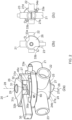
- Valve 20 comprises a valve body 25 defining three ports 21, 22, 23 extending radially outward from a cylindrical core portion 24 of the valve body 25 and a top cover 26 extending axially upward from the core portion 24 of the body 25.
- a valve core 27 Rotatably mounted within the core portion 24 is a valve core 27 which is rotatable about a valve axis 28 and secured to the top cover 26 by a securing feature 29 such as a screw, rivet, pin or other device which allows rotation of the valve core 27 relative to the valve body 25 but prevents axial displacement of the valve core relative to the valve body along the valve axis 28.
- the valve core 27 has a flanged base portion 27b with flange 27a extending radially outwards to cover the cylindrical bottom end 24b of the core portion 24 and be in sliding engagement therewith as the valve core rotates within the body 25.
- the base portion 27b of the valve core 27 may also include a direction indicator 27d disposed thereon which can provide a visual indication of the state of rotation of the valve core 27 externally of the body 25.
- the direction indicator 27d comprises a lug extending axially downwards from the base portion 27b and extending diametrically across the base portion 27b.
- the direction indicator 27d could alternatively be provided by way of an embossed surface or surface marking on the base portion 27b, for example.
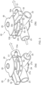
- the valve core 27 defines a ported chamber 40 having openings 41, 42, 43 respectively at 0, 180 and 90 degree positions relative to one another about the valve axis 28. These openings 41, 42, 43 are positioned to generally align with selected ones of the ports 21, 22, 23 when in certain angular positions within the valve body 25, as will be discussed later.
- a central shaft 44 extending axially upwards to engage with the securing feature 29 ( figure 2a ) when the valve core 27 is installed within the body 25.
- a peg 45 extending in an axially upward direction parallel to the central shaft 44 and radially displaced therefrom.
- the peg 45 has a clockwise-facing surface 45c and an anticlockwise-facing surface 45a.
- a pin ramp 46 comprising a channel or groove 46c cut into the circumferential surface 47 of the valve core.
- the channel 46c has a depth which varies as a function of circumferential position on the valve core 27 and terminates at a shallow end 46s with a locking pin hole 48 and terminates at a deep end 46d with a step surface 46e.
- a further pin ramp 56 comprising a channel or groove 56c is cut into the circumferential surface 47 of the valve core 27 and the channel 56c also has a depth which varies as a function of circumferential position on the valve core 27 and terminates at a shallow end 56s with a locking pin hole 58 and terminates at a deep end 56d with a step surface 56e.
- the valve 20 further comprises an operating lever 30 which is rotatable about the valve axis 28 and extends radially outwards from the top cover 26.
- the operating lever 30 is rotatable about the valve axis 28 relative to both the valve core 27 and the top cover 26, but in the arrangement shown, motion of the operating lever 30 is limited to an arc of approximately 90 degrees.
- the operating lever 30 is coupled to the valve core 27 by way of a pair of torsion springs 31, 32.
- the upper torsion spring 31 comprises a coil portion 31c around the valve axis 28, i.e.
- the lower torsion spring 32 comprises a coil portion 32c around the valve axis 28, i.e. around the central shaft 44 ( figure 4a ) and a first arm 32a which bears against an anticlockwise-facing surface 45a of the peg 45, and a second arm 32b which is engaged with the operating lever 30, e.g.
- the operating lever 30 is capable of applying both clockwise and anticlockwise rotational forces to the valve core 27 while still being capable of rotational motion relative to the valve core 27, for reasons to be explained hereinafter.
- the top cover 26 of the valve 20 further includes pin mounts 33a and 33b respectively supporting a first locking pin 34a and a second locking pin 34b.
- each locking pin 34 is displaceable along its axis which corresponds to a radial direction relative to the valve axis 28.
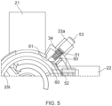
- Each locking pin 34 comprises a shaft 50, a biasing spring 51, a cam shoulder 52 and a spring adjustment screw mount 53.
- the cam shoulder 52 bears against the cam surface 61 of a cam ring 60 which extends around the valve core 27.
- the inner circumferential surface of the cam ring 60 is rotatable around, e.g.
- the cam ring 60 and the top portion 25t of the valve body 25 have elongate slots 80 therein (visible in figures 8a and 9 ) through which the shaft 50 of the respective locking pin 34 can pass to enter the respective locking pin hole 48, 58 when the locking pin 34 is spring-biased towards a radially inward position.
- the cam shoulder 52 of the locking pin 34 may be guided into a radially outward position when the cam shoulder 52 rides up a raised cam surface 61a and the cam shoulder 52 of the locking pin may be guided into a radially inward position when the cam shoulder 52 rides down the cam surface to a low cam surface 61b. In this way, the locking pin shaft 50 may be released from engagement with a respective pin hole 48, 58 of the valve core 27 to facilitate rotation of the valve core 27 about its axis.
- the cam ring 60 has a cam surface 61 which defines two raised cam surfaces 61a which are operable to lift the respective first and second locking pins 34a, 34b out of the respective locking pin holes 48, 58, and also two oppositely facing step features 62, 63.
- Clockwise-facing step feature 62 is engageable with an anticlockwise facing engagement surface 64 of the operating lever 30 ( figure 6a )
- anticlockwise-facing step feature 63 is engageable with a clockwise-facing engagement surface 65 of the operating level 30 ( figure 6b ).
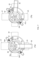
- FIGs 6a and 6b show the valve 20 respectively in the first and second configurations.
- the valve 20 is in a first stable configuration in which the first port 21 is in fluid communication with the second port 22 via the ported chamber 40 of the valve core 27, because opening 43 is in alignment with the first port 21 and opening 42 is in alignment with second port 22. See the inset schematic of valve core 27 showing its relative rotation position. It can also be seen that the third port 23 is blocked or occluded by the valve core 27 and therefore not in fluid communication with either the first port or the second port.
- valve 20 is in a second stable configuration in which the first port 21 is in fluid communication with the third port 23 via the ported chamber 40 of the valve core 27, because opening 42 is in alignment with the first port 21 and opening 41 is in alignment with third port 23. Opening 43 is occluded. See the inset schematic of valve core 27 showing its relative rotation position. It can also be seen that the second port 22 is blocked or occluded by the valve core 27 and therefore not in fluid communication with either the first port or the third port.
- valve 20 in performing the quarter-turn anticlockwise rotation of the valve core 27 when transitioning from the configuration of figure 6a to the configuration of figure 6b , dependent on the diameters of the openings 41-43 and the ports 21-23, and on the circumference of the valve core 27 / cylindrical core portion 24, the valve 20 can be configured as either a "break-before-make” type valve where the fluid flow from one port pair is completely shut off before the other fluid pair communication starts to be made, or vice versa ("make-before-break").
- first locking pin 34a is engaged with the corresponding locking pin hole 48, preventing rotation of the valve core 27.
- the second locking pin 34b may be positioned over the deep end 56d of the channel 56c, near the step surface 56e, in the valve core 27. It will be understood that the valve core 27 cannot rotate until the first locking pin 34a is released from its locking pin hole 48.
- second locking pin 34b is engaged with the corresponding locking pin hole 58, preventing rotation of the valve core 27.
- the first locking pin 34a may be positioned over the deep end 46d of the channel 46c, near the step surface 46e, in the valve core 27. It will be understood that the valve core 27 cannot rotate until the second locking pin 34b is released from its locking pin hole 58.
- the operating lever 30 is moved in an anticlockwise direction through approximately 90 degrees.
- the spring 31 stores considerable potential energy which strongly biases the valve core 27 for an anticlockwise rotation to follow the lever 30 motion.
- the first locking pin 34a prevents any such rotation of the valve core 27.
- the anticlockwise facing engagement surface 64 of the lever 30 engages the clockwise facing step feature 62 of the cam ring 60 causing the cam ring 60 to also rotate in an anticlockwise direction.
- the raised cam surface 61 drives the first locking pin 34a radially outward by engagement with the cam shoulder 52 thereby disengaging the locking pin shaft 50 from the locking pin hole 48 and thereby causing the valve core 27 to rapidly rotate in an anticlockwise direction under the accumulated spring bias in upper torsion spring 31.
- the second locking pin 34b travels up the pin ramp 56 to the shallow end 56s where it drops in to the locking pin hole 58. Further rotation of the valve core 27 is prevented by the second locking pin 34b dropping into the locking pin hole 58.
- a corresponding reverse movement of the operating lever 30 through approximately 90 degrees clockwise from the position of figure 6b uses the second (lower) torsion spring 32, the anticlockwise facing step feature 63 of the cam ring 60, and the second raised cam surface 61a to pre-load the second torsion spring 32 and then disengage the second locking pin 34b to trigger a corresponding reverse snap rotational movement of the valve core 27 from the stable position of figure 6b back to the stable position of figure 6a .
- the valve 20 exemplifies a bistable valve mechanism having (i) a first stable configuration in which the first port 21 is in fluid communication with the second port 22 and not the third port 23 and (ii) a second stable configuration in which the first port 21 is in fluid communication with the third port 23 and not the second port 22.
- the operating lever 30 and associated features exemplifies an actuator which is configured to transition the bistable valve mechanism between the two stable configurations while preventing the valve mechanism from maintaining a stable intermediate position between the first and second stable configurations.
- fluid communication is intended to encompass arrangements in which air or other gas flow between the communicating ports 21, 22, or 23 via the valve core 27 is sufficient in volume and sufficiently unimpeded to have little or no impact on the operation of a breathing circuit delivering gas to a patient's lungs via a breathing tube.
- the valve 20 thereby further exemplifies a bistable valve mechanism which comprises a moveable valve core 27 defining a ported chamber 40 for establishing respective fluid communication paths between the first and second or third ports 21,22, 23 in the first and second stable configurations, where the valve core 27 is coupled to and drivable by the actuator lever 30 via a spring loading mechanism exemplified by the torsion springs 31, 32, peg 45 and cam ring 60.
- the raised cam surfaces 61a of the cam ring 60 and their action on the respective locking pins 34a, 34b respectively determine first and second release positions to trigger transition of the valve core 27 from the first stable configuration to the second stable configuration, using the spring loading mechanism, upon reaching the first release position, and vice versa.
- the valve 20 described above is configured to act as a patient breathing circuit connector and may be configured for particular use with standardised patent assisted breathing apparatus. This may include providing standard fittings on each of the first, second and third ports 21, 22, 23.
- the first port 21 may be configured for connection to a patient airway maintaining device / breathing tube such as an endotracheal tube 2 or a tracheostomy tube, or via a suction device 3 connected thereto.
- the first port 21 may preferably comprise a male connector with a conical 22 mm outer diameter connector surface with a 1:40 taper and an internal co-axial conical connector with a 15 mm internal diameter (female) conical connector with a 1:40 taper.
- the second port 22 may be configured for connection to a ventilator 4 via breathing circuit tubing and can be left open to air when not in use.
- the second port 22 may comprise a female connector with a conical 22 mm internal diameter connector surface with a 1:40 taper.
- the third port 23 may be configured for connection to a second breathing circuit 6 and can also be left open to air when not in use.
- the third port 23 may comprise a female connector with a conical 22 mm internal diameter connector surface with a 1:40 taper.
- the valve may be specifically configured to be compatible with relevant national and/or international standards, such as ISO 5356-1:2004 or ISO 5356-1:2015 specifying dimensional and gauging requirements for cones and sockets intended for connecting anaesthetic and respiratory equipment, e.g. in breathing systems, anaesthetic-gas scavenging systems and vaporizers.
- the operating lever 30 allows switching from one breathing circuit 4 to another breathing circuit 6 while maintaining a closed circuit, thus preventing the release of potentially infected aerosols and minimizing the loss of positive end-expiratory pressure (PEEP) from the circuit.
- the valve may preferably be formed as a T-shaped device with ports at 90 / 180 degree relative angles, though other angular dispositions of the ports can be envisaged.
- the valve is preferably made principally from strong, lightweight plastic, e.g. with injection moulded parts, and is preferably a disposable device used for a single patient and for a limited period of time, e.g. up to a few days.
- Example materials may include polyethylene and polystyrene butadiene.
- the valve preferably transitions from one bistable state to the other bistable state in a period of time which is very small compared to the period of normal pressure changes within a patient's airway, e.g. substantially less than 1 second and preferably substantially less than 0.2 second.
- valve arrangements as described herein provide fast-acting transitions with a decisive and unambiguous snap action which provides strong haptic and audible feedback when the valve transitions between its bistable states. This is particularly useful in the clinical context for ensuring ease of use in a potentially noisy and confusing environment.
- the direction indicator 27d also provides clear visual feedback as to the status of the valve and cannot show an ambiguous intermediate indication as it is integrally formed with the bistable valve core 27.
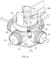
- Figures 8a, 8b and 9 illustrate a modification that incorporates higher performance sealing of the ports 21, 22, 23 to the valve core 27.
- one or more (and preferably all) of the first port 21, second port 22 and third port 23 may comprise an axially displaceable sealing member 81 which is configured to slide (left / right as viewed in figure 8b ) within a bore housing 82.
- a sliding seal 83 provides a sealing interface between the sealing member 81 and the bore housing 82 and a spring 88 biases the axially displaceable sealing member 81 towards the valve core 27.
- the axially displaceable sealing member 81 also includes an inner end 84 defining a face seal 85 which is brought into sealing engagement with the circumferential surface 47 of the valve core 27 when the sealing member 81 is in the (biased) extended position as shown in figure 8b .
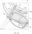
- Drive pins 86 extend downwardly from the cam ring 60 and each engages in a respective profiled slot 87 defining a cam surface in the axially displaceable sealing member 81.
- the profiled slot 87 in the axially displaceable sealing member 81 defines a cam surface 100 having first and second peak portions 101, 102 separated by a trough portion 103.
- the drive pins 86a, 86b do not touch, or do not bear against, the side walls of the profiled slot 87 and thus the sealing member is biased against the valve core 27 under the bias of spring 88, thereby effecting the best possible seal. This is applicable to all the axially displaceable sealing members 81 disposed around the valve core 27.
- the cam ring pins 86a, 86b start to move from the rest positions ( figure 11a ) to a position in which they engage the peak portions 101, 102 of the profiled slot 87 ( figure 11b ), thereby pushing the axially displaceable sealing member 81 away from the valve core 27 against the bias of spring 88.
- the face seal 85 is disengaged from the surface 47 of the valve core 27 thus reducing the resistance to motion of the valve core 27.
- valve core 27 rapidly rotates and the operating lever 30 / cam ring 60 rapidly complete their rotations leaving the cam ring pins 86a, 86b in the positions as seen in figure 11c .
- the first drive pin 86a has passed beyond the profiled slot 87 and the second drive pin 86b is aligned with the trough portion 103, and the displaceable sealing member 81 has been biased once again against the valve core 27 by the spring 88.
- a corresponding reverse action takes place when the operating lever 30 is rotated back to the first position.
- the valve 20 may be formed effectively with four bore housings 82 at 90 degree intervals around the body 25, each with an axially displaceable sealing member 81.
- one of the four bore housings 82 can be blanked off. This arrangement keeps the sealing arrangements symmetrical around the valve core 27, and may avoid the need for seals between the valve core 27 and the body 25, potentially reducing friction for a fast acting bistable valve.
- a three-port valve configuration is shown exemplifying a bistable valve mechanism in which a first port can be connected to either one of a second and third port by a rapidly transitioning valve mechanism. It will be understood that further ports could be added, and the actuator mechanism supplemented with a third position e.g. to provide a tristable valve mechanism. Such a tristable valve could have a position in which the first port can be connected to any one of a second, third or fourth port, or there could be a third stable position corresponding to a full isolated position where the first, second and third ports are all isolated from one another.
- the expression 'bistable valve' is intended to encompass a valve having at least a first and a second stable configuration in which an intermediate stable position between the first and second stable configurations is prevented, but need not exclude the possibility of having a further stable configuration while still meeting the specified bistable requirements.
- valve mechanism deploying linear motion
- the valve could be configured as a Y-shaped valve with the stem of the Y-shape corresponding to the first port and the two branches of the Y-shape corresponding to the second and third ports.
- a linear sliding bistable mechanism may be used to transition the valve from a first configuration in which the first port is in fluid communication with the second port to a second configuration in which the first port is in fluid communication with the third port.
- valves herein are preferably manually operated valves and constructed from low cost components.
- other electrically actuated versions may be envisaged.
- the valve as described above can be deployed to more safely switch a patient using a breathing support tube and connected to a first ventilation device to a second ventilation device with reduced risk of the problems identified above.
- the patient's breathing tube is coupled to the first port of the valve and the first ventilation device is coupled to the second port and the breathing apparatus is operated with the valve in the first stable configuration.
- a second ventilation device may be coupled to the third port.
- the valve may then be switched to the second stable configuration. After the transition of the valve to the second stable configuration the first ventilation device may be disconnected from the second port which has been isolated from the patient's active breathing circuit.
Landscapes
- Engineering & Computer Science (AREA)
- General Engineering & Computer Science (AREA)
- Health & Medical Sciences (AREA)
- Mechanical Engineering (AREA)
- Heart & Thoracic Surgery (AREA)
- Life Sciences & Earth Sciences (AREA)
- General Health & Medical Sciences (AREA)
- Biomedical Technology (AREA)
- Pulmonology (AREA)
- Hematology (AREA)
- Veterinary Medicine (AREA)
- Animal Behavior & Ethology (AREA)
- Anesthesiology (AREA)
- Public Health (AREA)
- Emergency Medicine (AREA)
- Infusion, Injection, And Reservoir Apparatuses (AREA)
- Magnetically Actuated Valves (AREA)
- Electrically Driven Valve-Operating Means (AREA)
- Temperature-Responsive Valves (AREA)
- Multiple-Way Valves (AREA)
- Mechanically-Actuated Valves (AREA)
Claims (15)
- Verbindungsventil zur Atemunterstützung, umfassend:erste, zweite und dritte Anschlüsse (21, 22, 23);einen bistabilen Ventilmechanismus mit (i) einer ersten stabilen Konfiguration, in der der erste Anschluss in Fluidverbindung mit dem zweiten Anschluss und nicht mit dem dritten Anschluss steht, und (ii) einer zweiten stabilen Konfiguration, in der der erste Anschluss in Fluidverbindung mit dem dritten Anschluss und nicht mit dem zweiten Anschluss steht; undeinen Aktuator (30), der so konfiguriert ist, dass er den bistabilen Ventilmechanismus zwischen den beiden stabilen Konfigurationen überführt, und dadurch gekennzeichnet, dass der Aktuator so konfiguriert ist, dass er verhindert, dass der Ventilmechanismus eine stabile Zwischenposition zwischen der ersten und der zweiten stabilen Konfiguration beibehält, und dass der bistabile Ventilmechanismus einen beweglichen Ventilkern (27) umfasst, der um eine Ventilachse (28) drehbar ist, und eine mit Anschlüssen versehene Kammer (40) zum Herstellen von Flüssigkeitsverbindungswegen zwischen ausgewählten der ersten, zweiten und dritten Anschlüssen in jeder der ersten und zweiten stabilen Konfigurationen definiert.
- Ventil nach Anspruch 1, wobei der Ventilkern über einen Federlademechanismus mit dem Aktuator verbunden und von diesem antreibbar ist, wobei der Aktuator so konfiguriert ist, dass er sich von einer ersten Position relativ zum Ventilkern bis zu einer ersten Freigabeposition bewegt, um den Federlademechanismus zu belasten, und um den Übergang des Ventilkerns von der ersten stabilen Konfiguration in die zweite stabile Konfiguration durch den Federlademechanismus bei Erreichen der ersten Freigabeposition auszulösen.
- Ventil nach Anspruch 2, bei dem der Aktuator so konfiguriert ist, dass er sich von einer zweiten Position relativ zum Ventilkern bis zu einer zweiten Freigabeposition bewegt, um den Federlademechanismus zu belasten, und um den Übergang des Ventilkerns von der zweiten stabilen Konfiguration in die erste stabile Konfiguration bei Erreichen der zweiten Freigabeposition auszulösen.
- Ventil nach Anspruch 2 oder Anspruch 3, bei dem der Aktuator mindestens einen ersten Verriegelungsstift (34a) umfasst, der mit dem beweglichen Ventilkern in Eingriff steht, um den Ventilkern in der ersten stabilen Konfiguration zu verriegeln, wobei der Aktuator so konfiguriert ist, dass er den ersten Verriegelungsstift vom Ventilkern löst, wenn er die erste Freigabeposition erreicht.
- Ventil nach einem der vorhergehenden Ansprüche, bei dem der Aktuator einen Hebel (30) umfasst, der um die Ventilachse drehbar ist.
- Ventil nach Anspruch 5, bei dem der Hebel über eine Torsionsfeder (31, 32) zwischen dem Hebel und einem sich axial erstreckenden Stift (45) am Ventilkern mit dem Ventilkern verbunden ist.
- Ventil nach Anspruch 4, ferner umfassend ein Nockenantriebselement, das neben dem Ventilkern angeordnet ist, wobei das Nockenantriebselement eine erste Nockenfläche (61), die mit dem ersten Verriegelungsstift in Eingriff steht, und ein Stufenmerkmal (62) umfasst, in das der Aktuator eingreifen kann, wenn er sich der ersten Freigabeposition nähert, um den ersten Verriegelungsstift so anzutreiben, dass er sich vom Ventilkern löst, wenn der Aktuator die erste Freigabeposition erreicht.
- Ventil nach Anspruch 5, bei dem der Ventilkern ferner (i) eine erste Stiftrampenfläche innerhalb eines Kanals, der sich zwischen einem ersten tiefen Ende und einem ersten Stiftaufnahmeloch an einem flachen Ende erstreckt, und (ii) eine zweite Stiftrampenfläche innerhalb eines Kanals umfasst, der sich zwischen einem zweiten tiefen Ende und einem zweiten Stiftaufnahmeloch an einem flachen Ende erstreckt, wobei die ersten und zweiten Stiftaufnahmelöcher jeweils so konfiguriert sind, dass sie eine weitere Bewegung des Ventilkerns über die jeweiligen bistabilen Positionen hinaus blockieren.
- Ventil nach einem der vorhergehenden Ansprüche, bei dem mindestens einer der ersten, zweiten und dritten Anschlüsse ein Bohrungsgehäuse (82) und ein axial verschiebbares Dichtungselement (81) innerhalb des Bohrungsgehäuses umfasst, das an einem Ende eine Gleitringdichtung (85) für den Eingriff mit dem Ventilkern und eine Gleitdichtung (83) für den gleitenden Eingriff mit dem Bohrungsgehäuse aufweist, wobei das Dichtungselement so gekoppelt ist, dass es von einer ausgefahrenen Position, in der die Flächendichtung mit dem Ventilkern in Eingriff ist, wenn sich der Aktuator in der ersten Position befindet, in eine zurückgezogene Position angetrieben werden kann, wenn sich der Aktuator über die erste Freigabeposition hinaus bewegt.
- Ventil nach Anspruch 9, bei dem das Dichtungselement so gekoppelt ist, dass es in die ausgefahrene Position zurückgetrieben wird, wobei die Flächendichtung mit dem Ventilkern in Eingriff steht, wenn der Ventilkern die zweite stabile Konfiguration erreicht, wobei die Flächendichtung des Dichtungselements durch eine Federvorspannung in Richtung des Ventilkerns vorgespannt ist.
- Ventil nach Anspruch 3, bei dem mindestens einer der ersten, zweiten und dritten Anschlüsse ein Bohrungsgehäuse und ein axial verschiebbares Dichtungselement innerhalb des Bohrungsgehäuses umfasst, das an einem Ende eine Gleitringdichtung für den Eingriff mit dem Ventilkern und eine Gleitdichtung für den gleitenden Eingriff mit dem Bohrungsgehäuse aufweist,wobei das Dichtungselement gekoppelt ist: (i) um aus einer ausgefahrenen Position, in der die Gleitringdichtung mit dem Ventilkern in Eingriff ist, wenn sich der Aktuator in der ersten Position befindet, in eine zurückgezogene Position angetrieben zu werden, wenn sich der Aktuator über die erste Freigabeposition hinaus bewegt, und (ii) um in die ausgefahrene Position zurückgetrieben zu werden, wobei die Flächendichtung mit dem Ventilkern in Eingriff steht, wenn der Ventilkern die zweite stabile Konfiguration erreicht; undwobei das Dichtungselement gekoppelt ist: (i) um von einer ausgefahrenen Position, wobei die Flächendichtung mit dem Ventilkern in Eingriff steht, wenn sich der Aktuator in der zweiten Position befindet, in die zurückgezogene Position angetrieben zu werden, wenn sich der Aktuator über die zweite Freigabeposition hinaus bewegt, und (ii) um in die ausgefahrene Position zurückgetrieben zu werden, wobei die Gleitringdichtung mit dem Ventilkern in Eingriff steht, wenn der Ventilkern die erste stabile Konfiguration erreicht.
- Ventil nach einem der Ansprüche 9 bis 11, bei dem jeder der ersten, zweiten und dritten Anschlüsse ein entsprechendes Bohrungsgehäuse und ein axial verschiebbares Dichtungselement umfasst, wobei das eine oder die mehreren axial verschiebbaren Dichtungselemente durch den Aktuator über ein Nockenantriebselement angetrieben werden, das neben dem Ventilkern angeordnet ist.
- Ventil nach einem der vorhergehenden Ansprüche, bei dem der erste Anschluss für den Anschluss an ein Gerät zur Aufrechterhaltung der Atemwege des Patienten konfiguriert ist und der zweite und der dritte Anschluss jeweils für den Anschluss an einen Beatmungskreislauf oder ein Atemunterstützungsgerät konfiguriert sind.
- Patientenbeatmungssystem, umfassend das Ventil nach einem der Ansprüche 1 bis 13 und eines oder beide von:einer Belüftungsvorrichtung, die mit mindestens einem der zweiten und dritten Anschlüsse verbunden ist; undeinen Atemschlauch, der mit dem ersten Anschluss verbunden ist.
- Verfahren zum Konfigurieren eines Atemunterstützungsgeräts für einen Patienten, umfassend:Bereitstellen eines Anschlussventils nach einem der Ansprüche 1 bis 13,Anschließen eines Patientenbeatmungsschlauchs an den ersten Anschluss,Koppeln eines ersten Belüftungsgeräts mit dem zweiten Anschluss,während sich das Ventil in der ersten stabilen Konfiguration befindet, Anschließen eines zweiten Belüftungsgeräts an den dritten Anschluss;Umschalten des Ventils in die zweite stabile Konfiguration; undTrennen des ersten Belüftungsgeräts vom zweiten Anschluss.
Applications Claiming Priority (2)
| Application Number | Priority Date | Filing Date | Title |
|---|---|---|---|
| GB2001683.8A GB2591794A (en) | 2020-02-07 | 2020-02-07 | Valve |
| PCT/GB2021/050261 WO2021156629A1 (en) | 2020-02-07 | 2021-02-05 | Valve |
Publications (2)
| Publication Number | Publication Date |
|---|---|
| EP4100672A1 EP4100672A1 (de) | 2022-12-14 |
| EP4100672B1 true EP4100672B1 (de) | 2024-01-31 |
Family
ID=69897071
Family Applications (1)
| Application Number | Title | Priority Date | Filing Date |
|---|---|---|---|
| EP21704921.2A Active EP4100672B1 (de) | 2020-02-07 | 2021-02-05 | Ventil |
Country Status (8)
| Country | Link |
|---|---|
| US (1) | US12578033B2 (de) |
| EP (1) | EP4100672B1 (de) |
| JP (1) | JP7688650B2 (de) |
| CN (1) | CN115315589A (de) |
| AU (1) | AU2021216262A1 (de) |
| CA (1) | CA3169047A1 (de) |
| GB (1) | GB2591794A (de) |
| WO (1) | WO2021156629A1 (de) |
Families Citing this family (2)
| Publication number | Priority date | Publication date | Assignee | Title |
|---|---|---|---|---|
| CN116672555B (zh) * | 2022-01-18 | 2025-08-01 | 河北金康安医疗器械科技有限公司 | 咳痰机的气路切换装置及咳痰系统 |
| KR102715017B1 (ko) * | 2023-01-06 | 2024-10-11 | 일레이트 메디컬, 인코포레이티드 | 셀을 포함하는 체액을 처리하기 위해 복수의 유로를 구비한 시스템에 포함되며 유로의 경로를 조작하기 위한 시스템 |
Family Cites Families (38)
| Publication number | Priority date | Publication date | Assignee | Title |
|---|---|---|---|---|
| US2311464A (en) * | 1939-12-13 | 1943-02-16 | Arthur L Parker | Valve assembly |
| US2702050A (en) | 1953-01-02 | 1955-02-15 | Stephen J Thomas | Two-way by-pass header valve |
| SU381812A1 (ru) * | 1970-09-24 | 1973-05-22 | Всесоюзный научно исследовательский , проектно конструкторский институт промышленных гидроприводов , гидроавтоматики | Пневматический переключатель |
| JPS4894696U (de) * | 1972-02-15 | 1973-11-12 | ||
| JPS4894696A (de) | 1972-03-15 | 1973-12-05 | ||
| JPS5019288U (de) * | 1973-06-13 | 1975-03-04 | ||
| JPS5655496Y2 (de) * | 1976-12-31 | 1981-12-24 | ||
| US4150694A (en) | 1977-07-27 | 1979-04-24 | Fluid Measurement Systems, Inc. | Rotary plug valve |
| US4493435A (en) * | 1982-11-10 | 1985-01-15 | Product Research And Development | Liquid dispensing system and automatic selector therefor |
| EP0438583A1 (de) | 1989-08-04 | 1991-07-31 | Nellcor Incorporated | Luftwegadapter mit reinigungsvorrichtung |
| CN2112736U (zh) | 1992-01-06 | 1992-08-12 | 中国石油天然气总公司辽河设计院 | 三通球阀 |
| NL9301212A (nl) * | 1993-06-29 | 1995-01-16 | Jager Beheer Management B V | Omschakelklep. |
| JPH07236696A (ja) * | 1994-02-28 | 1995-09-12 | Nippon Zeon Co Ltd | 多方活栓 |
| EP0700687A1 (de) | 1994-06-23 | 1996-03-13 | Ralph A. Milliken | T-Stück mit doppeltem Rückschlagventil und mit einem ein Gewinde aufweisenden, weiblichen Luerverbinder für Beatmungsgerät |
| DE19539655C1 (de) | 1995-10-25 | 1996-09-12 | Univ Schiller Jena | Dreiwege-Konnektor |
| US5746199A (en) * | 1996-08-21 | 1998-05-05 | Bayron; Harry | Respiratory valve |
| US5720282A (en) | 1996-09-06 | 1998-02-24 | Wright; Clifford | Universal respiratory apparatus and method of using same |
| US6634355B2 (en) | 1999-06-11 | 2003-10-21 | Colas Marie-Jose | Single breath induction anesthesia apparatus |
| WO2005003610A1 (en) * | 2003-07-01 | 2005-01-13 | Sabaf S.P.A. | Gas cock |
| JP4523314B2 (ja) | 2004-03-31 | 2010-08-11 | 株式会社山武 | 三方ボール弁 |
| CN201502749U (zh) | 2009-09-16 | 2010-06-09 | 四川苏克流体控制设备有限公司 | 三通球阀 |
| US8656915B2 (en) * | 2010-08-26 | 2014-02-25 | Baywin Too Llc | Respiratory valve |
| US20140036049A1 (en) | 2012-08-04 | 2014-02-06 | Robert Henderson Miller | Obstacle Avoidance for the Visually Impaired |
| US9435440B2 (en) | 2012-08-06 | 2016-09-06 | Mécanique Analytique Inc. | Valve with a loading varying mechanism, and method of operating the same |
| CN203154594U (zh) | 2012-11-12 | 2013-08-28 | 怡安医疗器材股份有限公司 | 密闭式抽痰管的开关装置及密闭式抽痰管系统 |
| DE202013006445U1 (de) | 2013-07-17 | 2013-08-08 | Dräger Medical GmbH | Beatmungsschlaucheinheit und Bausatz mit Beatmungsschlaucheinheit |
| CN104864119A (zh) | 2014-02-21 | 2015-08-26 | 浙江三花旋转阀有限公司 | 一种旋转式流路切换阀 |
| US10279137B1 (en) | 2014-06-27 | 2019-05-07 | Orlando Morejon | Connector assembly for a medical ventilator system |
| US10926053B2 (en) | 2014-11-25 | 2021-02-23 | The General Hospital Corporation | Closed-circuit breathing device |
| CN204744830U (zh) * | 2015-05-08 | 2015-11-11 | 濡新(北京)科技发展有限公司 | 一种三通阀 |
| WO2016182536A1 (en) * | 2015-05-08 | 2016-11-17 | Volvo Truck Corporation | Three-way valve |
| CN204774830U (zh) | 2015-06-12 | 2015-11-18 | 苏州中航中振汽车饰件有限公司 | 带有可折叠置物桌的汽车座椅 |
| DE102015110732A1 (de) | 2015-07-03 | 2017-01-05 | Claudia Röttger-Lanfranchi | Konnektor für den Einsatz in ein Beatmungssystem |
| CN105805358A (zh) | 2016-05-28 | 2016-07-27 | 许昌东方热力有限公司 | 一种新型锁控三通球阀 |
| WO2018010680A1 (en) | 2016-07-14 | 2018-01-18 | The Hong Kong Polytechnic University | Rose petal textured haze film for photovoltaic cells |
| CN109216395B (zh) | 2017-07-06 | 2023-08-04 | 乐金显示有限公司 | 发光结构、发光晶体管及其制造方法 |
| CN209959990U (zh) * | 2019-04-11 | 2020-01-17 | 佟晨光 | 加油机输出管紧急切断保护装置及加油机 |
| CN211536125U (zh) | 2019-11-11 | 2020-09-22 | 广州医科大学附属第一医院(广州呼吸中心) | 一种医用三通接头 |
-
2020
- 2020-02-07 GB GB2001683.8A patent/GB2591794A/en not_active Withdrawn
-
2021
- 2021-02-05 AU AU2021216262A patent/AU2021216262A1/en active Pending
- 2021-02-05 JP JP2022547822A patent/JP7688650B2/ja active Active
- 2021-02-05 CN CN202180018355.1A patent/CN115315589A/zh active Pending
- 2021-02-05 EP EP21704921.2A patent/EP4100672B1/de active Active
- 2021-02-05 US US17/798,006 patent/US12578033B2/en active Active
- 2021-02-05 WO PCT/GB2021/050261 patent/WO2021156629A1/en not_active Ceased
- 2021-02-05 CA CA3169047A patent/CA3169047A1/en active Pending
Also Published As
| Publication number | Publication date |
|---|---|
| EP4100672A1 (de) | 2022-12-14 |
| GB202001683D0 (en) | 2020-03-25 |
| CA3169047A1 (en) | 2021-08-12 |
| GB2591794A (en) | 2021-08-11 |
| AU2021216262A1 (en) | 2022-08-25 |
| US20230052770A1 (en) | 2023-02-16 |
| US12578033B2 (en) | 2026-03-17 |
| WO2021156629A1 (en) | 2021-08-12 |
| CN115315589A (zh) | 2022-11-08 |
| JP7688650B2 (ja) | 2025-06-04 |
| JP2023513167A (ja) | 2023-03-30 |
Similar Documents
| Publication | Publication Date | Title |
|---|---|---|
| US20240325675A1 (en) | Valve | |
| AU734483B2 (en) | Suction control valve | |
| US12578033B2 (en) | Valve | |
| US11571540B2 (en) | Respiratory valve apparatus and related method | |
| US5337780A (en) | Suction control valve | |
| KR101615096B1 (ko) | 호흡기 액세스 조립체 | |
| US8770190B2 (en) | Connectors for connecting components of a breathing apparatus | |
| US5377672A (en) | Suction control valve | |
| US20130267919A1 (en) | Solenoid activated vacuum control device | |
| US20080236590A1 (en) | Respiratory Device Comprising a Double Lumen Endotracheal Tube | |
| WO2004034946A2 (en) | Improved respiratory valve | |
| WO2012027107A1 (en) | Improved respiratory valve | |
| JP2013514851A (ja) | ピンロックを備えた呼吸器アクセスポートアセンブリ及びその使用方法 | |
| US12539414B2 (en) | Systems and methods for blood pump connectors | |
| US10589054B2 (en) | Valve assemblies | |
| US10279137B1 (en) | Connector assembly for a medical ventilator system | |
| US20230330376A1 (en) | Respiratory valve apparatus and related methods | |
| CN223453517U (zh) | 一种呼吸接头和密闭式吸痰管 | |
| CN222510610U (zh) | 一种密闭式吸痰管的连接控制开关及密闭式吸痰管 | |
| US20260131134A1 (en) | Systems and methods for blood pump connectors | |
| CN121288137A (zh) | 一种连接阀与医疗设备 | |
| WO2016027043A1 (en) | Speaking valves, tracheostomy tubes and assemblies | |
| CN121371414A (zh) | 一种医用气管插管 |
Legal Events
| Date | Code | Title | Description |
|---|---|---|---|
| STAA | Information on the status of an ep patent application or granted ep patent |
Free format text: STATUS: UNKNOWN |
|
| STAA | Information on the status of an ep patent application or granted ep patent |
Free format text: STATUS: THE INTERNATIONAL PUBLICATION HAS BEEN MADE |
|
| PUAI | Public reference made under article 153(3) epc to a published international application that has entered the european phase |
Free format text: ORIGINAL CODE: 0009012 |
|
| STAA | Information on the status of an ep patent application or granted ep patent |
Free format text: STATUS: REQUEST FOR EXAMINATION WAS MADE |
|
| 17P | Request for examination filed |
Effective date: 20220725 |
|
| AK | Designated contracting states |
Kind code of ref document: A1 Designated state(s): AL AT BE BG CH CY CZ DE DK EE ES FI FR GB GR HR HU IE IS IT LI LT LU LV MC MK MT NL NO PL PT RO RS SE SI SK SM TR |
|
| DAV | Request for validation of the european patent (deleted) | ||
| DAX | Request for extension of the european patent (deleted) | ||
| GRAP | Despatch of communication of intention to grant a patent |
Free format text: ORIGINAL CODE: EPIDOSNIGR1 |
|
| STAA | Information on the status of an ep patent application or granted ep patent |
Free format text: STATUS: GRANT OF PATENT IS INTENDED |
|
| INTG | Intention to grant announced |
Effective date: 20230901 |
|
| GRAS | Grant fee paid |
Free format text: ORIGINAL CODE: EPIDOSNIGR3 |
|
| GRAA | (expected) grant |
Free format text: ORIGINAL CODE: 0009210 |
|
| STAA | Information on the status of an ep patent application or granted ep patent |
Free format text: STATUS: THE PATENT HAS BEEN GRANTED |
|
| P01 | Opt-out of the competence of the unified patent court (upc) registered |
Effective date: 20231220 |
|
| AK | Designated contracting states |
Kind code of ref document: B1 Designated state(s): AL AT BE BG CH CY CZ DE DK EE ES FI FR GB GR HR HU IE IS IT LI LT LU LV MC MK MT NL NO PL PT RO RS SE SI SK SM TR |
|
| REG | Reference to a national code |
Ref country code: GB Ref legal event code: FG4D Ref country code: CH Ref legal event code: EP |
|
| REG | Reference to a national code |
Ref country code: DE Ref legal event code: R096 Ref document number: 602021008990 Country of ref document: DE |
|
| REG | Reference to a national code |
Ref country code: IE Ref legal event code: FG4D |
|
| REG | Reference to a national code |
Ref country code: LT Ref legal event code: MG9D |
|
| REG | Reference to a national code |
Ref country code: NL Ref legal event code: MP Effective date: 20240131 |
|
| PG25 | Lapsed in a contracting state [announced via postgrant information from national office to epo] |
Ref country code: IS Free format text: LAPSE BECAUSE OF FAILURE TO SUBMIT A TRANSLATION OF THE DESCRIPTION OR TO PAY THE FEE WITHIN THE PRESCRIBED TIME-LIMIT Effective date: 20240531 |
|
| PG25 | Lapsed in a contracting state [announced via postgrant information from national office to epo] |
Ref country code: LT Free format text: LAPSE BECAUSE OF FAILURE TO SUBMIT A TRANSLATION OF THE DESCRIPTION OR TO PAY THE FEE WITHIN THE PRESCRIBED TIME-LIMIT Effective date: 20240131 |
|
| PG25 | Lapsed in a contracting state [announced via postgrant information from national office to epo] |
Ref country code: GR Free format text: LAPSE BECAUSE OF FAILURE TO SUBMIT A TRANSLATION OF THE DESCRIPTION OR TO PAY THE FEE WITHIN THE PRESCRIBED TIME-LIMIT Effective date: 20240501 |
|
| REG | Reference to a national code |
Ref country code: AT Ref legal event code: MK05 Ref document number: 1654089 Country of ref document: AT Kind code of ref document: T Effective date: 20240131 |
|
| PG25 | Lapsed in a contracting state [announced via postgrant information from national office to epo] |
Ref country code: RS Free format text: LAPSE BECAUSE OF FAILURE TO SUBMIT A TRANSLATION OF THE DESCRIPTION OR TO PAY THE FEE WITHIN THE PRESCRIBED TIME-LIMIT Effective date: 20240430 Ref country code: HR Free format text: LAPSE BECAUSE OF FAILURE TO SUBMIT A TRANSLATION OF THE DESCRIPTION OR TO PAY THE FEE WITHIN THE PRESCRIBED TIME-LIMIT Effective date: 20240131 Ref country code: NL Free format text: LAPSE BECAUSE OF FAILURE TO SUBMIT A TRANSLATION OF THE DESCRIPTION OR TO PAY THE FEE WITHIN THE PRESCRIBED TIME-LIMIT Effective date: 20240131 |
|
| PG25 | Lapsed in a contracting state [announced via postgrant information from national office to epo] |
Ref country code: ES Free format text: LAPSE BECAUSE OF FAILURE TO SUBMIT A TRANSLATION OF THE DESCRIPTION OR TO PAY THE FEE WITHIN THE PRESCRIBED TIME-LIMIT Effective date: 20240131 |
|
| PG25 | Lapsed in a contracting state [announced via postgrant information from national office to epo] |
Ref country code: AT Free format text: LAPSE BECAUSE OF FAILURE TO SUBMIT A TRANSLATION OF THE DESCRIPTION OR TO PAY THE FEE WITHIN THE PRESCRIBED TIME-LIMIT Effective date: 20240131 |
|
| PG25 | Lapsed in a contracting state [announced via postgrant information from national office to epo] |
Ref country code: RS Free format text: LAPSE BECAUSE OF FAILURE TO SUBMIT A TRANSLATION OF THE DESCRIPTION OR TO PAY THE FEE WITHIN THE PRESCRIBED TIME-LIMIT Effective date: 20240430 Ref country code: NO Free format text: LAPSE BECAUSE OF FAILURE TO SUBMIT A TRANSLATION OF THE DESCRIPTION OR TO PAY THE FEE WITHIN THE PRESCRIBED TIME-LIMIT Effective date: 20240430 Ref country code: NL Free format text: LAPSE BECAUSE OF FAILURE TO SUBMIT A TRANSLATION OF THE DESCRIPTION OR TO PAY THE FEE WITHIN THE PRESCRIBED TIME-LIMIT Effective date: 20240131 Ref country code: LT Free format text: LAPSE BECAUSE OF FAILURE TO SUBMIT A TRANSLATION OF THE DESCRIPTION OR TO PAY THE FEE WITHIN THE PRESCRIBED TIME-LIMIT Effective date: 20240131 Ref country code: IS Free format text: LAPSE BECAUSE OF FAILURE TO SUBMIT A TRANSLATION OF THE DESCRIPTION OR TO PAY THE FEE WITHIN THE PRESCRIBED TIME-LIMIT Effective date: 20240531 Ref country code: HR Free format text: LAPSE BECAUSE OF FAILURE TO SUBMIT A TRANSLATION OF THE DESCRIPTION OR TO PAY THE FEE WITHIN THE PRESCRIBED TIME-LIMIT Effective date: 20240131 Ref country code: GR Free format text: LAPSE BECAUSE OF FAILURE TO SUBMIT A TRANSLATION OF THE DESCRIPTION OR TO PAY THE FEE WITHIN THE PRESCRIBED TIME-LIMIT Effective date: 20240501 Ref country code: FI Free format text: LAPSE BECAUSE OF FAILURE TO SUBMIT A TRANSLATION OF THE DESCRIPTION OR TO PAY THE FEE WITHIN THE PRESCRIBED TIME-LIMIT Effective date: 20240131 Ref country code: ES Free format text: LAPSE BECAUSE OF FAILURE TO SUBMIT A TRANSLATION OF THE DESCRIPTION OR TO PAY THE FEE WITHIN THE PRESCRIBED TIME-LIMIT Effective date: 20240131 Ref country code: BG Free format text: LAPSE BECAUSE OF FAILURE TO SUBMIT A TRANSLATION OF THE DESCRIPTION OR TO PAY THE FEE WITHIN THE PRESCRIBED TIME-LIMIT Effective date: 20240131 Ref country code: AT Free format text: LAPSE BECAUSE OF FAILURE TO SUBMIT A TRANSLATION OF THE DESCRIPTION OR TO PAY THE FEE WITHIN THE PRESCRIBED TIME-LIMIT Effective date: 20240131 |
|
| PG25 | Lapsed in a contracting state [announced via postgrant information from national office to epo] |
Ref country code: PL Free format text: LAPSE BECAUSE OF FAILURE TO SUBMIT A TRANSLATION OF THE DESCRIPTION OR TO PAY THE FEE WITHIN THE PRESCRIBED TIME-LIMIT Effective date: 20240131 Ref country code: PT Free format text: LAPSE BECAUSE OF FAILURE TO SUBMIT A TRANSLATION OF THE DESCRIPTION OR TO PAY THE FEE WITHIN THE PRESCRIBED TIME-LIMIT Effective date: 20240531 |
|
| PG25 | Lapsed in a contracting state [announced via postgrant information from national office to epo] |
Ref country code: SE Free format text: LAPSE BECAUSE OF FAILURE TO SUBMIT A TRANSLATION OF THE DESCRIPTION OR TO PAY THE FEE WITHIN THE PRESCRIBED TIME-LIMIT Effective date: 20240131 Ref country code: PT Free format text: LAPSE BECAUSE OF FAILURE TO SUBMIT A TRANSLATION OF THE DESCRIPTION OR TO PAY THE FEE WITHIN THE PRESCRIBED TIME-LIMIT Effective date: 20240531 Ref country code: PL Free format text: LAPSE BECAUSE OF FAILURE TO SUBMIT A TRANSLATION OF THE DESCRIPTION OR TO PAY THE FEE WITHIN THE PRESCRIBED TIME-LIMIT Effective date: 20240131 Ref country code: LV Free format text: LAPSE BECAUSE OF FAILURE TO SUBMIT A TRANSLATION OF THE DESCRIPTION OR TO PAY THE FEE WITHIN THE PRESCRIBED TIME-LIMIT Effective date: 20240131 |
|
| REG | Reference to a national code |
Ref country code: CH Ref legal event code: PL |
|
| PG25 | Lapsed in a contracting state [announced via postgrant information from national office to epo] |
Ref country code: DK Free format text: LAPSE BECAUSE OF FAILURE TO SUBMIT A TRANSLATION OF THE DESCRIPTION OR TO PAY THE FEE WITHIN THE PRESCRIBED TIME-LIMIT Effective date: 20240131 |
|
| PG25 | Lapsed in a contracting state [announced via postgrant information from national office to epo] |
Ref country code: SM Free format text: LAPSE BECAUSE OF FAILURE TO SUBMIT A TRANSLATION OF THE DESCRIPTION OR TO PAY THE FEE WITHIN THE PRESCRIBED TIME-LIMIT Effective date: 20240131 |
|
| PG25 | Lapsed in a contracting state [announced via postgrant information from national office to epo] |
Ref country code: LU Free format text: LAPSE BECAUSE OF NON-PAYMENT OF DUE FEES Effective date: 20240205 |
|
| PG25 | Lapsed in a contracting state [announced via postgrant information from national office to epo] |
Ref country code: CH Free format text: LAPSE BECAUSE OF NON-PAYMENT OF DUE FEES Effective date: 20240229 |
|
| PG25 | Lapsed in a contracting state [announced via postgrant information from national office to epo] |
Ref country code: EE Free format text: LAPSE BECAUSE OF FAILURE TO SUBMIT A TRANSLATION OF THE DESCRIPTION OR TO PAY THE FEE WITHIN THE PRESCRIBED TIME-LIMIT Effective date: 20240131 Ref country code: CZ Free format text: LAPSE BECAUSE OF FAILURE TO SUBMIT A TRANSLATION OF THE DESCRIPTION OR TO PAY THE FEE WITHIN THE PRESCRIBED TIME-LIMIT Effective date: 20240131 |
|
| PG25 | Lapsed in a contracting state [announced via postgrant information from national office to epo] |
Ref country code: SK Free format text: LAPSE BECAUSE OF FAILURE TO SUBMIT A TRANSLATION OF THE DESCRIPTION OR TO PAY THE FEE WITHIN THE PRESCRIBED TIME-LIMIT Effective date: 20240131 |
|
| PG25 | Lapsed in a contracting state [announced via postgrant information from national office to epo] |
Ref country code: SM Free format text: LAPSE BECAUSE OF FAILURE TO SUBMIT A TRANSLATION OF THE DESCRIPTION OR TO PAY THE FEE WITHIN THE PRESCRIBED TIME-LIMIT Effective date: 20240131 Ref country code: SK Free format text: LAPSE BECAUSE OF FAILURE TO SUBMIT A TRANSLATION OF THE DESCRIPTION OR TO PAY THE FEE WITHIN THE PRESCRIBED TIME-LIMIT Effective date: 20240131 Ref country code: RO Free format text: LAPSE BECAUSE OF FAILURE TO SUBMIT A TRANSLATION OF THE DESCRIPTION OR TO PAY THE FEE WITHIN THE PRESCRIBED TIME-LIMIT Effective date: 20240131 Ref country code: LU Free format text: LAPSE BECAUSE OF NON-PAYMENT OF DUE FEES Effective date: 20240205 Ref country code: EE Free format text: LAPSE BECAUSE OF FAILURE TO SUBMIT A TRANSLATION OF THE DESCRIPTION OR TO PAY THE FEE WITHIN THE PRESCRIBED TIME-LIMIT Effective date: 20240131 Ref country code: DK Free format text: LAPSE BECAUSE OF FAILURE TO SUBMIT A TRANSLATION OF THE DESCRIPTION OR TO PAY THE FEE WITHIN THE PRESCRIBED TIME-LIMIT Effective date: 20240131 Ref country code: CZ Free format text: LAPSE BECAUSE OF FAILURE TO SUBMIT A TRANSLATION OF THE DESCRIPTION OR TO PAY THE FEE WITHIN THE PRESCRIBED TIME-LIMIT Effective date: 20240131 Ref country code: CH Free format text: LAPSE BECAUSE OF NON-PAYMENT OF DUE FEES Effective date: 20240229 |
|
| REG | Reference to a national code |
Ref country code: DE Ref legal event code: R097 Ref document number: 602021008990 Country of ref document: DE |
|
| PG25 | Lapsed in a contracting state [announced via postgrant information from national office to epo] |
Ref country code: MC Free format text: LAPSE BECAUSE OF FAILURE TO SUBMIT A TRANSLATION OF THE DESCRIPTION OR TO PAY THE FEE WITHIN THE PRESCRIBED TIME-LIMIT Effective date: 20240131 |
|
| PG25 | Lapsed in a contracting state [announced via postgrant information from national office to epo] |
Ref country code: MC Free format text: LAPSE BECAUSE OF FAILURE TO SUBMIT A TRANSLATION OF THE DESCRIPTION OR TO PAY THE FEE WITHIN THE PRESCRIBED TIME-LIMIT Effective date: 20240131 |
|
| PG25 | Lapsed in a contracting state [announced via postgrant information from national office to epo] |
Ref country code: IT Free format text: LAPSE BECAUSE OF FAILURE TO SUBMIT A TRANSLATION OF THE DESCRIPTION OR TO PAY THE FEE WITHIN THE PRESCRIBED TIME-LIMIT Effective date: 20240131 |
|
| PLBE | No opposition filed within time limit |
Free format text: ORIGINAL CODE: 0009261 |
|
| STAA | Information on the status of an ep patent application or granted ep patent |
Free format text: STATUS: NO OPPOSITION FILED WITHIN TIME LIMIT |
|
| REG | Reference to a national code |
Ref country code: BE Ref legal event code: MM Effective date: 20240229 |
|
| PG25 | Lapsed in a contracting state [announced via postgrant information from national office to epo] |
Ref country code: IT Free format text: LAPSE BECAUSE OF FAILURE TO SUBMIT A TRANSLATION OF THE DESCRIPTION OR TO PAY THE FEE WITHIN THE PRESCRIBED TIME-LIMIT Effective date: 20240131 |
|
| 26N | No opposition filed |
Effective date: 20241101 |
|
| PG25 | Lapsed in a contracting state [announced via postgrant information from national office to epo] |
Ref country code: BE Free format text: LAPSE BECAUSE OF NON-PAYMENT OF DUE FEES Effective date: 20240229 |
|
| PG25 | Lapsed in a contracting state [announced via postgrant information from national office to epo] |
Ref country code: IE Free format text: LAPSE BECAUSE OF NON-PAYMENT OF DUE FEES Effective date: 20240205 |
|
| PG25 | Lapsed in a contracting state [announced via postgrant information from national office to epo] |
Ref country code: IE Free format text: LAPSE BECAUSE OF NON-PAYMENT OF DUE FEES Effective date: 20240205 Ref country code: BE Free format text: LAPSE BECAUSE OF NON-PAYMENT OF DUE FEES Effective date: 20240229 |
|
| PG25 | Lapsed in a contracting state [announced via postgrant information from national office to epo] |
Ref country code: SI Free format text: LAPSE BECAUSE OF FAILURE TO SUBMIT A TRANSLATION OF THE DESCRIPTION OR TO PAY THE FEE WITHIN THE PRESCRIBED TIME-LIMIT Effective date: 20240131 |
|
| PG25 | Lapsed in a contracting state [announced via postgrant information from national office to epo] |
Ref country code: CY Free format text: LAPSE BECAUSE OF FAILURE TO SUBMIT A TRANSLATION OF THE DESCRIPTION OR TO PAY THE FEE WITHIN THE PRESCRIBED TIME-LIMIT; INVALID AB INITIO Effective date: 20210205 |
|
| PG25 | Lapsed in a contracting state [announced via postgrant information from national office to epo] |
Ref country code: HU Free format text: LAPSE BECAUSE OF FAILURE TO SUBMIT A TRANSLATION OF THE DESCRIPTION OR TO PAY THE FEE WITHIN THE PRESCRIBED TIME-LIMIT; INVALID AB INITIO Effective date: 20210205 |
|
| PG25 | Lapsed in a contracting state [announced via postgrant information from national office to epo] |
Ref country code: TR Free format text: LAPSE BECAUSE OF FAILURE TO SUBMIT A TRANSLATION OF THE DESCRIPTION OR TO PAY THE FEE WITHIN THE PRESCRIBED TIME-LIMIT Effective date: 20240131 |
|
| PGFP | Annual fee paid to national office [announced via postgrant information from national office to epo] |
Ref country code: GB Payment date: 20260129 Year of fee payment: 6 |
|
| PGFP | Annual fee paid to national office [announced via postgrant information from national office to epo] |
Ref country code: DE Payment date: 20260217 Year of fee payment: 6 |
|
| PGFP | Annual fee paid to national office [announced via postgrant information from national office to epo] |
Ref country code: FR Payment date: 20260223 Year of fee payment: 6 |