EP4100583B1 - Verbindungsknoten für modulare gebäudestrukturen - Google Patents
Verbindungsknoten für modulare gebäudestrukturen Download PDFInfo
- Publication number
- EP4100583B1 EP4100583B1 EP21750534.6A EP21750534A EP4100583B1 EP 4100583 B1 EP4100583 B1 EP 4100583B1 EP 21750534 A EP21750534 A EP 21750534A EP 4100583 B1 EP4100583 B1 EP 4100583B1
- Authority
- EP
- European Patent Office
- Prior art keywords
- coupler
- bolt
- connection part
- diameter
- diaphragm plate
- Prior art date
- Legal status (The legal status is an assumption and is not a legal conclusion. Google has not performed a legal analysis and makes no representation as to the accuracy of the status listed.)
- Active
Links
Images






Classifications
-
- E—FIXED CONSTRUCTIONS
- E04—BUILDING
- E04B—GENERAL BUILDING CONSTRUCTIONS; WALLS, e.g. PARTITIONS; ROOFS; FLOORS; CEILINGS; INSULATION OR OTHER PROTECTION OF BUILDINGS
- E04B1/00—Constructions in general; Structures which are not restricted either to walls, e.g. partitions, or floors or ceilings or roofs
- E04B1/18—Structures comprising elongated load-supporting parts, e.g. columns, girders, skeletons
- E04B1/24—Structures comprising elongated load-supporting parts, e.g. columns, girders, skeletons the supporting parts consisting of metal
- E04B1/2403—Connection details of the elongated load-supporting parts
-
- F—MECHANICAL ENGINEERING; LIGHTING; HEATING; WEAPONS; BLASTING
- F16—ENGINEERING ELEMENTS AND UNITS; GENERAL MEASURES FOR PRODUCING AND MAINTAINING EFFECTIVE FUNCTIONING OF MACHINES OR INSTALLATIONS; THERMAL INSULATION IN GENERAL
- F16B—DEVICES FOR FASTENING OR SECURING CONSTRUCTIONAL ELEMENTS OR MACHINE PARTS TOGETHER, e.g. NAILS, BOLTS, CIRCLIPS, CLAMPS, CLIPS OR WEDGES; JOINTS OR JOINTING
- F16B12/00—Jointing of furniture or the like, e.g. hidden from exterior
- F16B12/40—Joints for furniture tubing
-
- E—FIXED CONSTRUCTIONS
- E04—BUILDING
- E04B—GENERAL BUILDING CONSTRUCTIONS; WALLS, e.g. PARTITIONS; ROOFS; FLOORS; CEILINGS; INSULATION OR OTHER PROTECTION OF BUILDINGS
- E04B1/00—Constructions in general; Structures which are not restricted either to walls, e.g. partitions, or floors or ceilings or roofs
- E04B1/348—Structures composed of units comprising at least considerable parts of two sides of a room, e.g. box-like or cell-like units closed or in skeleton form
- E04B1/34815—Elements not integrated in a skeleton
- E04B1/3483—Elements not integrated in a skeleton the supporting structure consisting of metal
-
- E—FIXED CONSTRUCTIONS
- E04—BUILDING
- E04B—GENERAL BUILDING CONSTRUCTIONS; WALLS, e.g. PARTITIONS; ROOFS; FLOORS; CEILINGS; INSULATION OR OTHER PROTECTION OF BUILDINGS
- E04B1/00—Constructions in general; Structures which are not restricted either to walls, e.g. partitions, or floors or ceilings or roofs
- E04B1/38—Connections for building structures in general
- E04B1/388—Separate connecting elements
-
- E—FIXED CONSTRUCTIONS
- E04—BUILDING
- E04G—SCAFFOLDING; FORMS; SHUTTERING; BUILDING IMPLEMENTS OR AIDS, OR THEIR USE; HANDLING BUILDING MATERIALS ON THE SITE; REPAIRING, BREAKING-UP OR OTHER WORK ON EXISTING BUILDINGS
- E04G21/00—Preparing, conveying, or working-up building materials or building elements in situ; Other devices or measures for constructional work
- E04G21/14—Conveying or assembling building elements
- E04G21/142—Means in or on the elements for connecting same to handling apparatus
-
- F—MECHANICAL ENGINEERING; LIGHTING; HEATING; WEAPONS; BLASTING
- F16—ENGINEERING ELEMENTS AND UNITS; GENERAL MEASURES FOR PRODUCING AND MAINTAINING EFFECTIVE FUNCTIONING OF MACHINES OR INSTALLATIONS; THERMAL INSULATION IN GENERAL
- F16B—DEVICES FOR FASTENING OR SECURING CONSTRUCTIONAL ELEMENTS OR MACHINE PARTS TOGETHER, e.g. NAILS, BOLTS, CIRCLIPS, CLAMPS, CLIPS OR WEDGES; JOINTS OR JOINTING
- F16B12/00—Jointing of furniture or the like, e.g. hidden from exterior
- F16B12/10—Jointing of furniture or the like, e.g. hidden from exterior using pegs, bolts, tenons, clamps, clips, or the like
- F16B12/28—Jointing of furniture or the like, e.g. hidden from exterior using pegs, bolts, tenons, clamps, clips, or the like for metal furniture parts
- F16B12/30—Jointing of furniture or the like, e.g. hidden from exterior using pegs, bolts, tenons, clamps, clips, or the like for metal furniture parts using threaded bolts
-
- F—MECHANICAL ENGINEERING; LIGHTING; HEATING; WEAPONS; BLASTING
- F16—ENGINEERING ELEMENTS AND UNITS; GENERAL MEASURES FOR PRODUCING AND MAINTAINING EFFECTIVE FUNCTIONING OF MACHINES OR INSTALLATIONS; THERMAL INSULATION IN GENERAL
- F16B—DEVICES FOR FASTENING OR SECURING CONSTRUCTIONAL ELEMENTS OR MACHINE PARTS TOGETHER, e.g. NAILS, BOLTS, CIRCLIPS, CLAMPS, CLIPS OR WEDGES; JOINTS OR JOINTING
- F16B45/00—Hooks; Eyes
- F16B45/002—Eyes
-
- F—MECHANICAL ENGINEERING; LIGHTING; HEATING; WEAPONS; BLASTING
- F16—ENGINEERING ELEMENTS AND UNITS; GENERAL MEASURES FOR PRODUCING AND MAINTAINING EFFECTIVE FUNCTIONING OF MACHINES OR INSTALLATIONS; THERMAL INSULATION IN GENERAL
- F16B—DEVICES FOR FASTENING OR SECURING CONSTRUCTIONAL ELEMENTS OR MACHINE PARTS TOGETHER, e.g. NAILS, BOLTS, CIRCLIPS, CLAMPS, CLIPS OR WEDGES; JOINTS OR JOINTING
- F16B7/00—Connections of rods or tubes, e.g. of non-circular section, mutually, including resilient connections
- F16B7/04—Clamping or clipping connections
- F16B7/0406—Clamping or clipping connections for rods or tubes being coaxial
- F16B7/0413—Clamping or clipping connections for rods or tubes being coaxial for tubes using the innerside thereof
-
- F—MECHANICAL ENGINEERING; LIGHTING; HEATING; WEAPONS; BLASTING
- F16—ENGINEERING ELEMENTS AND UNITS; GENERAL MEASURES FOR PRODUCING AND MAINTAINING EFFECTIVE FUNCTIONING OF MACHINES OR INSTALLATIONS; THERMAL INSULATION IN GENERAL
- F16B—DEVICES FOR FASTENING OR SECURING CONSTRUCTIONAL ELEMENTS OR MACHINE PARTS TOGETHER, e.g. NAILS, BOLTS, CIRCLIPS, CLAMPS, CLIPS OR WEDGES; JOINTS OR JOINTING
- F16B7/00—Connections of rods or tubes, e.g. of non-circular section, mutually, including resilient connections
- F16B7/18—Connections of rods or tubes, e.g. of non-circular section, mutually, including resilient connections using screw-thread elements
- F16B7/182—Connections of rods or tubes, e.g. of non-circular section, mutually, including resilient connections using screw-thread elements for coaxial connections of two rods or tubes
-
- F—MECHANICAL ENGINEERING; LIGHTING; HEATING; WEAPONS; BLASTING
- F16—ENGINEERING ELEMENTS AND UNITS; GENERAL MEASURES FOR PRODUCING AND MAINTAINING EFFECTIVE FUNCTIONING OF MACHINES OR INSTALLATIONS; THERMAL INSULATION IN GENERAL
- F16B—DEVICES FOR FASTENING OR SECURING CONSTRUCTIONAL ELEMENTS OR MACHINE PARTS TOGETHER, e.g. NAILS, BOLTS, CIRCLIPS, CLAMPS, CLIPS OR WEDGES; JOINTS OR JOINTING
- F16B7/00—Connections of rods or tubes, e.g. of non-circular section, mutually, including resilient connections
- F16B7/18—Connections of rods or tubes, e.g. of non-circular section, mutually, including resilient connections using screw-thread elements
- F16B7/185—Connections of rods or tubes, e.g. of non-circular section, mutually, including resilient connections using screw-thread elements with a node element
-
- F—MECHANICAL ENGINEERING; LIGHTING; HEATING; WEAPONS; BLASTING
- F16—ENGINEERING ELEMENTS AND UNITS; GENERAL MEASURES FOR PRODUCING AND MAINTAINING EFFECTIVE FUNCTIONING OF MACHINES OR INSTALLATIONS; THERMAL INSULATION IN GENERAL
- F16B—DEVICES FOR FASTENING OR SECURING CONSTRUCTIONAL ELEMENTS OR MACHINE PARTS TOGETHER, e.g. NAILS, BOLTS, CIRCLIPS, CLAMPS, CLIPS OR WEDGES; JOINTS OR JOINTING
- F16B9/00—Connections of rods or tubular parts to flat surfaces at an angle
- F16B9/05—Connections of rods or tubular parts to flat surfaces at an angle by way of an intermediate member
- F16B9/054—Connections of rods or tubular parts to flat surfaces at an angle by way of an intermediate member the intermediate member being threaded
-
- E—FIXED CONSTRUCTIONS
- E04—BUILDING
- E04B—GENERAL BUILDING CONSTRUCTIONS; WALLS, e.g. PARTITIONS; ROOFS; FLOORS; CEILINGS; INSULATION OR OTHER PROTECTION OF BUILDINGS
- E04B1/00—Constructions in general; Structures which are not restricted either to walls, e.g. partitions, or floors or ceilings or roofs
- E04B1/18—Structures comprising elongated load-supporting parts, e.g. columns, girders, skeletons
- E04B1/24—Structures comprising elongated load-supporting parts, e.g. columns, girders, skeletons the supporting parts consisting of metal
- E04B1/2403—Connection details of the elongated load-supporting parts
- E04B2001/2406—Connection nodes
-
- E—FIXED CONSTRUCTIONS
- E04—BUILDING
- E04B—GENERAL BUILDING CONSTRUCTIONS; WALLS, e.g. PARTITIONS; ROOFS; FLOORS; CEILINGS; INSULATION OR OTHER PROTECTION OF BUILDINGS
- E04B1/00—Constructions in general; Structures which are not restricted either to walls, e.g. partitions, or floors or ceilings or roofs
- E04B1/18—Structures comprising elongated load-supporting parts, e.g. columns, girders, skeletons
- E04B1/24—Structures comprising elongated load-supporting parts, e.g. columns, girders, skeletons the supporting parts consisting of metal
- E04B1/2403—Connection details of the elongated load-supporting parts
- E04B2001/2415—Brackets, gussets, joining plates
-
- E—FIXED CONSTRUCTIONS
- E04—BUILDING
- E04B—GENERAL BUILDING CONSTRUCTIONS; WALLS, e.g. PARTITIONS; ROOFS; FLOORS; CEILINGS; INSULATION OR OTHER PROTECTION OF BUILDINGS
- E04B1/00—Constructions in general; Structures which are not restricted either to walls, e.g. partitions, or floors or ceilings or roofs
- E04B1/18—Structures comprising elongated load-supporting parts, e.g. columns, girders, skeletons
- E04B1/24—Structures comprising elongated load-supporting parts, e.g. columns, girders, skeletons the supporting parts consisting of metal
- E04B1/2403—Connection details of the elongated load-supporting parts
- E04B2001/2418—Details of bolting
-
- E—FIXED CONSTRUCTIONS
- E04—BUILDING
- E04B—GENERAL BUILDING CONSTRUCTIONS; WALLS, e.g. PARTITIONS; ROOFS; FLOORS; CEILINGS; INSULATION OR OTHER PROTECTION OF BUILDINGS
- E04B1/00—Constructions in general; Structures which are not restricted either to walls, e.g. partitions, or floors or ceilings or roofs
- E04B1/18—Structures comprising elongated load-supporting parts, e.g. columns, girders, skeletons
- E04B1/24—Structures comprising elongated load-supporting parts, e.g. columns, girders, skeletons the supporting parts consisting of metal
- E04B1/2403—Connection details of the elongated load-supporting parts
- E04B2001/2451—Connections between closed section profiles
-
- E—FIXED CONSTRUCTIONS
- E04—BUILDING
- E04B—GENERAL BUILDING CONSTRUCTIONS; WALLS, e.g. PARTITIONS; ROOFS; FLOORS; CEILINGS; INSULATION OR OTHER PROTECTION OF BUILDINGS
- E04B1/00—Constructions in general; Structures which are not restricted either to walls, e.g. partitions, or floors or ceilings or roofs
- E04B1/18—Structures comprising elongated load-supporting parts, e.g. columns, girders, skeletons
- E04B1/24—Structures comprising elongated load-supporting parts, e.g. columns, girders, skeletons the supporting parts consisting of metal
- E04B1/2403—Connection details of the elongated load-supporting parts
- E04B2001/246—Post to post connections
-
- E—FIXED CONSTRUCTIONS
- E04—BUILDING
- E04B—GENERAL BUILDING CONSTRUCTIONS; WALLS, e.g. PARTITIONS; ROOFS; FLOORS; CEILINGS; INSULATION OR OTHER PROTECTION OF BUILDINGS
- E04B1/00—Constructions in general; Structures which are not restricted either to walls, e.g. partitions, or floors or ceilings or roofs
- E04B1/18—Structures comprising elongated load-supporting parts, e.g. columns, girders, skeletons
- E04B1/24—Structures comprising elongated load-supporting parts, e.g. columns, girders, skeletons the supporting parts consisting of metal
- E04B2001/2466—Details of the elongated load-supporting parts
-
- E—FIXED CONSTRUCTIONS
- E04—BUILDING
- E04B—GENERAL BUILDING CONSTRUCTIONS; WALLS, e.g. PARTITIONS; ROOFS; FLOORS; CEILINGS; INSULATION OR OTHER PROTECTION OF BUILDINGS
- E04B1/00—Constructions in general; Structures which are not restricted either to walls, e.g. partitions, or floors or ceilings or roofs
- E04B1/18—Structures comprising elongated load-supporting parts, e.g. columns, girders, skeletons
- E04B1/24—Structures comprising elongated load-supporting parts, e.g. columns, girders, skeletons the supporting parts consisting of metal
- E04B2001/2496—Shear bracing therefor
-
- E—FIXED CONSTRUCTIONS
- E04—BUILDING
- E04B—GENERAL BUILDING CONSTRUCTIONS; WALLS, e.g. PARTITIONS; ROOFS; FLOORS; CEILINGS; INSULATION OR OTHER PROTECTION OF BUILDINGS
- E04B1/00—Constructions in general; Structures which are not restricted either to walls, e.g. partitions, or floors or ceilings or roofs
- E04B1/35—Extraordinary methods of construction, e.g. lift-slab, jack-block
- E04B2001/3583—Extraordinary methods of construction, e.g. lift-slab, jack-block using permanent tensioning means, e.g. cables or rods, to assemble or rigidify structures (not pre- or poststressing concrete), e.g. by tying them around the structure
-
- F—MECHANICAL ENGINEERING; LIGHTING; HEATING; WEAPONS; BLASTING
- F16—ENGINEERING ELEMENTS AND UNITS; GENERAL MEASURES FOR PRODUCING AND MAINTAINING EFFECTIVE FUNCTIONING OF MACHINES OR INSTALLATIONS; THERMAL INSULATION IN GENERAL
- F16B—DEVICES FOR FASTENING OR SECURING CONSTRUCTIONAL ELEMENTS OR MACHINE PARTS TOGETHER, e.g. NAILS, BOLTS, CIRCLIPS, CLAMPS, CLIPS OR WEDGES; JOINTS OR JOINTING
- F16B2200/00—Constructional details of connections not covered for in other groups of this subclass
- F16B2200/50—Flanged connections
- F16B2200/506—Flanged connections bolted or riveted
Definitions
- the present invention relates to a connection system for use in connecting prefabricated building modules together and to a module support component having connection node assembly components formed therein.
- Each module is a generally box shaped unit with a primary chassis comprising vertical support posts and horizontal cross members joined together at corner nodes.
- the vertical supports in a module are hollow support structure (HSS), such as steel profiles with a square or rectangular cross-section.
- HSS hollow support structure
- a prefabricated module may also be at least partially finished with internal walls, flooring, and hookups for electricity and water.
- an initial tier of modules is installed horizontally and affixed to a building foundation or previously installed substructure. Adjacent top corners of the modules are connected together with a joining plate. A second tier of modules is positioned over the first tier, aligned and positioned in place. The bottom corners of the second tier modules are then affixed to the top corners of the first tier modules.
- An advantage of using prefabricated modules is that they can be assembled inside and remotely from the construction site, reducing the amount of outdoor work that must be done at the construction site itself. Notwithstanding, job-site construction often continues in a wide variety of weather conditions. To prevent water from getting into the module assembly and damaging pre-installed components, the module, as supplied, can have an outer weatherproofing layer.
- volumetric modular buildings rely on a separate structure to provide lateral stability against horizontal loads (such as a concrete core or an external steel brace-frame).
- Each module is only responsible for carrying vertical loads to the tiers below through its vertical columns.
- Standard methods and systems for connecting prefab building modules during erection are designed to ensure vertical continuity between stacked columns and horizontal continuity between modules of the same level. Continuity is typically achieved by means of large joining plates to connect the corners of adjacent modules. These plates extend well past the vertical support members and are affixed to structures on the horizontal support beams where the connection points are accessible by the installers.
- JP 2001 254445 A discloses a connection system wherein two superimposed hollow bodies are connected by a bolt housed in a conical seat at a bottom end of the upper hollow body and threadedly engaging a bore in a conical guiding pin provided at an upper end of the lower hollow body.
- connection node system as claimed in claim 1.
- connection node system is largely integrated within the vertical supports that are used in chassis of a modular building unit.
- Each respective vertical support has a hollow elongated body that extends along a central axis.
- a first connection portion is formed at the bottom of each support and will be the top portion of the connection node system when that support is mounted on top of a lower support.
- the first connection portion has an axial bore through it opening into the interior of the support.
- the axial bore is configured so that a connecting bolt can be passed down through the interior of the support and seat on a shoulder within the bore with the bolt's shank extending out from the support.
- a second connection portion is formed on the top of each support and will be the bottom portion of the connection node system when that support is mounted beneath an upper support.
- the second connection portion comprises an axial hole extending to the interior of the support.
- the axial hole has a diameter throughout greater than the head diameter of the connecting bolts to permit a bolt and associated drive socket to be fed through the second connection portion and through the support's interior allowing the bolt to engage the bore in the first connection portion.
- the axial hole should also be large enough to allow a tool for tightening the bolt to be passed through.
- the axial hole has an internally facing shoulder and is configured so a coupler nut in an insertion position can be placed into the axial hole along the axis and then rotated axially to a captured position where the shoulder blocks axial motion of the coupler towards the second end.
- the coupler nut has a threaded aperture to receive the shank of the bolt extending out from the first connection portion of an upper support.
- the supports can be steel hollow support structures that can have a rectangular (including square) or other cross-sectional shape.
- the coupling nut can have the same cross-section shape as the support or a different shape.
- the axial hole has a first open area adjacent to the end of the support.
- the first open area can have the same cross-section shape as the coupling nut and is large enough to allow the nut to pass through.
- a second open area is axially inward and adjacent to the first open area.
- the second open area can have a circular cross-section with a diameter substantially the same as the maximum diameter of the first open area.
- the larger second open area defines inward facing shoulders adjacent to the first open area which prevents the coupler nut from being removed when rotated to a captured position.
- a third open area formed inward from the second area nut keeps the coupler nut from passing inward beyond the second area.
- the first open area can have the same shape or different shape as the support cross-section, such as square, and can be rotated thereto so that sides defining the first open area are not parallel to the sides of the support.
- One or more locking holes can be provided in the end surface of the second connecting part and that extend through to the second open area.
- the locking holes are positioned so that when a locking pin is inserted into the locking hole, the locking pin restricts rotation of a coupler in the captured position within the second open area.
- a diaphragm plate can be provided to connect the tops of horizontally adjacent vertical supports.
- the diaphragm plate has a plurality of bolt apertures that are positioned to align with the threaded apertures in coupler nuts mounted in the second connection portions of the adjacent supports.
- the diaphragm plate can also have vertically extending alignment members (such as circular or diamond profile pins or cones) that mate with corresponding alignment features in the first connecting portion of a vertical support being lowered therein.
- Alignment holes can also be formed in the diaphragm plate and the second connecting portion and/or the coupler nut.
- the alignment holes are positioned so that when the coupler is in the captured position in the second connection part, the diaphragm plate can be positioned over the second connection part with the diaphragm alignment hole and coupler alignment hole axially aligned and the bolt aperture axially aligned with the axial hole in the second connector part.
- Locking bolts placed through the diaphragm alignment holes and into the coupler alignment holes can be used to temporarily hold the diaphragm plate in alignment over one vertical support while the vertical support from an upper module is lowered over another portion of the diaphragm.
- a bolt can also be temporarily inserted through the diaphragm plate into the coupler nut. Once the diaphragm is clamped in place under that other vertical support, the locking bolts and diaphragm plate bolt can be removed.
- a lifting plate with the same basic shape as the coupler nut can also be provided. Instead of a threaded aperture, the lifting plate has a lifting eye.
- the lifting plate can be mounted in the second portion of the vertical supports (e.g., at the top) in the same manner as a coupler nut and the lifting eye used as a cable connection point for hoisting the module into place. When the module is correctly placed, the lifting plate can be removed.
- the internal bolting configuration allows building modules to be connected without having to disturb existing weatherproofing.
- the diaphragm plate can also be reduced in size so that it only covers the tops of the adjacent vertical supports, reducing weight and material cost.
- the connection node system allows a node of eight module corners (where four upper and four lower modules come together) to be securely joined together using only four bolts and an appropriately configured diaphragm plate. Because a connecting bolt is inserted through the top of the vertical support on an upper module and tightened using an elongated wrench assembly operated from above the upper, module workers need to spend less time working at the bottom of a module thereby increasing worker safety.
- the bolted connection can resist tension as required by various building codes, even if the connection remains in compression during its use in all load cases.
- the bolt can be pre-tensioned during construction during the stacking procedure.
- This bolted connection turns individual module columns into continuous steel columns from the bottom to the top of the building.
- neighboring corner columns sit side by side in configurations of two (at the fa ade) or four (internally).
- At the corners and irregular shaped areas of a building there may also be configurations of one (i.e. a single column) or three. Differently shaped modules, such as hexagons, would have more possible configurations.
- the diaphragm plate placed on top of columns connects side by side neighboring columns together during stacking.
- the column bolts from the modules above pass through holes in the diaphragm plate and the diaphragm plate operates to create a tying load path laterally between all columns in the group.
- the chassis components can be assembled at the offsite module assembly facility by bolting the components together. This allows for efficient transport to the module assembly facility by transporting the pre-assembled frames and beams in a flat pack configuration rather than a volumetric configuration. This enables the industry best practice of not "shipping air”.
- the simple bolted construction at the offsite assembly facility eliminates any need for welded joints, thus reducing the time to assemble and inspect the components, and reducing the labor content overall.
- the lack of welding at the assembly facility and the construction site reduces the level of skill required to erect the building and lowers the overall cost of labor and inspection.
- the bolted connections provide for significantly tighter control of build tolerances, allowing for stacking with a curtain wall fa ade pre-installed on the modules.
- Components can be machined for tight tolerance assembly and then assembled and inspected to tighter tolerances without incurring significant cost.
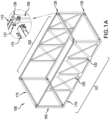
- Fig. 1A is an illustration of a representative chassis 100 that can form the support structure of a prefabricated building module.
- the chassis comprises rectangular front and rear portions 101, 102, each having a pair of vertical supports 105 and top and bottom horizontal supports 110.
- the front and rear portions 101, 102 are connected to each other with horizontal beams 115.
- the chassis can also have various other structural elements, such as posts or wall studs 120 and cross supports 125.
- Vertical supports 105 are hollow support structures (HSS) and can have a rectangular (including square), or other shape cross-section. A square cross-section is illustrated.
- HSS hollow support structures
- the various vertical supports 105, horizontal supports 110 and horizontal beams 115 are joined at each corner with a top connecting part 130 (for top chassis corners) or bottom connecting part 135 (for the bottom chassis corners).
- the connections of the horizontal supports and beams 110,115 to the connecting part 130, 135 can be made using conventional techniques.
- the vertical supports 105 and horizontal supports 110 are connected to a respective top and bottom corner connecting parts 130, 135 using welds and the horizontal beams 115 are bolted in place at a joining assembly 137 such as a butt joint, shown in more detail in Fig. 1C .
- Other connection means could be used.
- a flange can extend from a corner connecting part 130 and be connected to a horizontal beam 115 in a bolted-together lap joint, shown in more detail in Fig. 1D .
- the top and bottom connecting parts 130 are made of steel that is milled or cast into the proper configuration.
- the vertical supports are also steel.
- Vertical supports 105 can be provided, e.g., to a facility where the chassis are to be prefabricated, with the top and bottom connecting parts 130 already attached and the top and bottom ends of the assembly milled to create a flat bearing connection surface.
- Fig. 2 is an exploded view of a connection node system 200 showing a top connecting part 130 and bottom connecting part 135 along with connecting hardware including a threaded coupler nut 205 (such as one having an integral threaded aperture or a separate captive threaded nut), a diaphragm plate 210, bolt 215, shims 220 and diaphragm temporary locking bolts 225.
- a threaded coupler nut 205 such as one having an integral threaded aperture or a separate captive threaded nut
- a diaphragm plate 210 bolt 215, shims 220 and diaphragm temporary locking bolts 225.
- the diaphragm plate 210 is mounted over the top connecting part 130 and can be aligned and temporarily held in place with diaphragm locking bolts 225.
- the diaphragm plate 210 can be used to connect connecting part 130 to one or more adjacent connecting parts 130 from adjacent chasses 100 and different diaphragm plate configurations can be provided according to the number of corners at a node, such as two along the facade and four at an interior connection.
- the bottom connecting part 135 is attached to the top connecting part 130 using bolt 215.
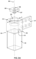
- Fig. 3A is a more detailed view of the top connecting part 130 and coupler nut 205.
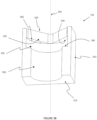
- Fig. 3B shows a cross section of the top connecting part 130 of Fig. 3A along line A-A.
- Top connecting part 130 is mounted at a top end 106 of a vertical support 105. In one configuration, the top connecting part 130 fits into the opening at the top end 106 of vertical support and can be welded or otherwise affixed into place. Other ways of joining the top connecting part 130 to the vertical support 105 can be used as well.
- the top connecting part 130 has a top surface 310.
- Vertical support 105 defines a central axis 305.
- An axial hole 325 runs from the top surface 310 to the interior of the vertical support 105.
- Axial hole 325 is configured so that bolt 215 can pass completely through the top connecting part 130 and into the interior of the vertical support 105.
- the axial hole 325 has a diameter throughout that is greater than the maximum diameter D of the head 216 of bolt 215 so the bolt 215 can be in any rotational orientation and still pass through top connecting part 130 into the vertical support 105.
- a narrower axial hole 235 could be provided if there is a need to prevent the bolt from passing into the vertical support unless it is in a correct rotational orientation.
- the top connecting part defines a bottom surface 315 within the vertical support 105.
- Joining assembly 137 can comprise one or more flanges welded or otherwise affixed to respective sides 320 of the top connecting part 130 to allow attachment of horizontal supports.
- a flat mount for a butt joint or other connection structure could be provided instead.
- the axial hole 325 has a first portion that is adjacent the top surface 310 and defines a first open area 330 into which the coupler nut 205 can be placed.
- a second portion of the axial hole defines a second open area 335 adjacent the first open area 330.
- the second open area 335 defines at least one shoulder 340 that is adjacent to the first open area 330.
- the coupler nut 205, first open area 330 and second area 335 are configured so that the coupler nut 205 when in an insertion position can pass through the first open area 330 and into the second open area 335 and can be rotated from the insertion position to a captured position where the shoulder 340 prevents removal of the coupler nut 205 through the first open area 330.
- the coupler nut 205 has a triangular, square, or other angular or curved geometric shape with a horizontal diameter that is not the same along all azimuth angles.
- the first open area 330 has substantially the same shape as the coupler nut 205 and is sized to allow the coupler nut 205 to be easily inserted without too much play.
- the second open area 335 has a circular cross section large enough to allow the coupler nut 205 to spin freely without too much play so that the aperture 206 in the coupler nut 205 remains substantially aligned with the central axis 305.
- the coupler nut is used for securing the top connecting part 130 to the bottom connecting part 135 in conjunction with the bolt 215. While the shape of the nut plate 205 and the first and second open areas 330, 335 can vary there is a balancing between increasing the surface area of the nut plate 205 that engages the shoulder 340 so that the assembly can withstand high forces involved in coupling chasses 100 together while also providing an opening large enough to allow easy access.
- the opening for the coupler nut is rotated relative to the vertical support 105 cross section, such as between 30 and 60 degrees, and in an embodiment substantially at 45 degrees.
- the final locked position of the coupler nut 205 engages a comparatively large amount of metal within the top connecting part 130 and increases the stress resistance of the total node assembly.
- Other relative rotational positions can be used for the design, including no rotation, which may make it easier to fabricate the top connecting part 130 by casting or other means.
- the coupler nut 205 can be a single integral unit with the threaded aperture 206 formed directly therein.
- the threaded aperture 206 can be provided by a captive bolt 207 formed separately from and connected to the coupler 205.
- a locking pin 345 can be inserted through a coupler locking hole 350.
- the locking pin 345 extends into the second open area 335 and functions to restrict rotation of the coupler nut 205 from its captured position.
- Fig. 3C is a cross section of the top connecting part of Fig. 3A illustrating a seated coupler nut and locking pins 345.
- two locking holes 350 are provided and positioned so that inserted locking pins 345 will bracket a corner of the coupler nut 205 and limit the amount the coupler nut can rotate so as to prevent its removal.
- locking holes 351 (not shown) can be formed in the coupler nut 205. The locking holes 350 are positioned so the locking pin 345 can pass into the locking holes 351 in the coupler nut.
- a third open area 355 can be formed beneath the second open area 335.
- the third open area 355 defines shoulders 360 at the bottom of the second open area 335 that keep the coupler nut 205 within the second open area 335 so it does not fall into the vertical support 105.
- the third open area 355 has a circular cross-section with a diameter that is less than the diameter of the second open area but greater than the diameter D of the bolt head 216.
- Fig 4A is a more detailed view of the bottom connecting part 135.
- Fig. 4B shows a cross section of the bottom connecting part 135 of Fig. 4A along line B-B.
- Bottom connecting part 135 is mounted at a bottom end 107 of a vertical support 105 (shown in phantom in Fig 4A ).
- the bottom connecting part 135 fits into the opening at the bottom end 107 of vertical support 105 and can be welded or otherwise affixed into place. Other ways of joining the bottom connecting part 135 to the vertical support 105 can be used as well.
- bottom connecting part 135 has a bore 410 that extends through it along a central axis.
- the bore 410 has an upper bore part opening 415 at a top 420 of the bottom connecting part 135 and a lower bore part opening 425 that opens at the bottom 430 of the bottom connecting part 135.
- the diameter of the bore 410 at the upper opening 415 is greater than the bolt head 216 diameter D1 and the bore diameter throughout is greater than the diameter D2 of the shank 217 of bolt 215.
- Between top and bottom of the bore 425 is a constricted area through which the bolt shank 217 but not the bolt head 216 can pass.
- the upper bore part is conical and ends at a shoulder 435 on which the head 216 of the bolt 215 can rest when the bolt 215 is inserted into the bottom connecting part.
- the lower bore part is cylindrical with a diameter large enough to allow the bolt shank 217 to pass through easily and to provide sufficient clearance to accommodate normal fabrication, assembly, and erection tolerances, but to also maximize the contact area under the head of the bolt.
- the diameter of the bore 410 from the upper opening 415 to the shoulder 435 can be constant.
- An alignment opening 440 can be provided in the bottom surface 430 and be configured to receive an alignment member 211 extending upwards from the diaphragm plate 210 during assembly of the connection node.
- the alignment opening 440 and alignment member 211 help to properly align the bottom connecting part 135 with the diaphragm plate and the top connecting part 130 in a lower chassis to which the diaphragm plate is connected.
- More than one alignment opening 440 can be provided.
- multiple alignment openings 440 can be provided to allow the same bottom connecting part 135 to mount to a diaphragm plate 210 on the left or on the right.
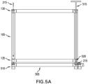
- Figs. 5A - 5C illustrate a method for joining chassis in a modular building using the connection node assembly.
- Fig. 5A shows a first chassis mounted to a foundation 505.
- the foundation 505 has mounting points 510 to which the bottom connecting parts 135 of the chassis can be joined.
- the mounting points 510 can be modified versions of a top connecting part 130 or have another configuration for receiving bolt 215.
- Fig. 5A shows an already assembled chassis 100. It should be appreciated that the vertical support 105 with the top connecting part 130 and bottom connecting part 135 already connected can be provided as a single part for use during construction of a chassis 100.
- connection node system Because of the unique configuration of the connection node system, once the chassis is aligned over the mounting points 510 it can be fixed in place without requiring a worker at the base of the chassis or inside of the chassis.
- Bolt 215 is dropped or otherwise lowered through the central bore 410 of the top connecting part 130. It passes through the hollow vertical support 105 and is captured by the bore 410 in the bottom connecting part 130.
- An elongated wrench assembly 515 can be inserted through the top connecting part 130 and lowered through the vertical support 105 until the socket 520 at the end of the wrench seats on the head of 216 of the bolt. Wrench assembly 515 is then used to tighten the bolt 215 and secure the chassis in place on the foundation 505.
- the bolt could be pre-inserted into the central bore before the chassis is lifted into place and temporarily held in place with wax, hot glue, or other similar substance.
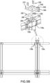
- Fig. 5B illustrates the connection of two adjacent top connecting parts 130a, 130b from horizontally adjacent chassis.
- a respective coupler nut 205 is mounted and locked into place as discussed above.
- the diaphragm plate 210 is then positioned over the top connecting parts 130a, 130b.
- One more leveling shims 220 can be added to adjust the vertical height of the diaphragm plate 210.
- the diaphragm plate and shims have bolt apertures 540, 525 through which a bolt 215 will later pass.
- one or more alignment holes 545, 530 are formed on the diaphragm plate 210 and shim 220 respectively.
- One or more corresponding alignment holes 535 are formed on the coupler nut 205.
- the alignment holes 545, 525, 535 will be aligned.
- locking bolts 225 can be inserted through holes 545, 525, 535 and serve to lock the diaphragm plate 210 and shim 220 in the proper place over the coupling nut 205.
- a temporary bolt (not shown) can also be passed through the bolt apertures 540, 525, 535. The position of a secured diaphragm plate can be surveyed to allow for repositioning of each floor to the building nominal coordinate system.
- the locking bolts 225 and temporary bolt are installed over only one top connecting part, such as 130a.
- the diaphragm plate 210 Once a portion of the diaphragm plate 210 is secured to one chassis, such as chassis 130b, by the placement of another chassis above it (see Fig. 5C ), the diaphragm plate 210 will then be held securely in place and the locking bolts 225 and temporary bolt can be removed so the locking bolts 225 do not interfere with the placement of the next chassis coming in.
- the temporary bolt also functions to close the main opening in the top connecting part to prevent water from getting into the hollow vertical support 105 if construction is occurring during wet weather.
- the bolt apertures 545 that receive the locking bolts 225 can have a diameter large enough to allow the locking bolts 225 to float in the holes to allow for misalignment. If misalignment is less of a concern, locking bolts 225 could be counterbored into the diaphragm plate 210 so removal is not needed.
- the diaphragm plate 210 can be shaped and sized according to the number and arrangement corners of a chassis to be joined at the node.
- the diaphragm plate 210 is configured so that it fully covers the top surfaces 310 of the top connecting parts 130 at the node and where the sides 550 of the diaphragm plate 210 are generally aligned with the exterior sides of the top connecting parts at that node. (See Fig. 7 discussed further below.)
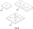
- the configuration of the alignment members can vary in different diaphragm plates 210 according to where in the structure the node is located and the stacking sequence of the chassis.
- close fit cones are placed on the diaphragm plates used near the fa ade portions of the chassis to tightly control the position of the chassis in that area.
- Diamond cones are used on diaphragm plates at the other end of the chassis to control the rotation of the chassis.
- a given diaphragm plate can have anywhere from zero to four alignment members.
- Various different diaphragm plate configurations 210a, 210b, 210c are shown in Fig. 8 .
- alignment members known to those of ordinary skill in the art can be provided to, for example, position the chassis in x/y or manage rotation of the chassis about the alignment cone.
- the alignment members can be integrally formed with the diaphragm plate or the diaphragm plate can have suitable mounting apertures and the appropriate alignment members installed separately.
- Fig. 5C shows the installation of a third chassis over one of the chassis shown in Fig. 5B .
- an upper chassis is lifted into place, its lower corners are generally aligned with the top corners of the chassis below, and then the chassis is lowered into place.
- One or more alignment members 211 on the diaphragm plate 210 mate with the corresponding alignment opening 440 at the bottom of bottom connecting part 135 to guide the upper chassis into proper alignment so that the central axis of the vertical supports 105 in the upper and lower chassis are aligned.
- Fig. 5D shows a cross section view of a fully connected node assembly at an inner node where upper and four lower chasses come together.
- a lifting plate 606 having a lifting eye 610 can be locked into the top connecting parts 130 in each corner of the chassis.
- the lifting plate has the same cross sectional shape as the coupler nut 205 and can be secured to the top connecting part in the same manner. Cables 615 can be connected to the lifting eyes for use in lifting the chassis into place. After placement, the substitute nut plate 606 can be removed.
- Fig. 6A shows one corner of a chassis 100 connected for lifting in this manner.
- bolts 215 can be inserted into the top connecting parts in the upper chassis, such as top connecting part 130c.
- the bolt 215 passes through the respective bottom connecting part 135 and engages the threaded aperture 206 in the coupling nut 205 mounted therein.
- the bolt 215 is then tightened using the elongated wrench assembly 515 (see Fig. 5 ) to couple the top and bottom connecting parts 130, 135 at each corner together.
- the bolted connection turns individual module columns connected along a vertical axis into continuous steel columns from the bottom to the top of the building.
- the bolted connect also clamps the diaphragm plate 210 between the chassis' columns and creates a tying load path laterally between all columns in the group. Once portion of the diaphragm plate 210 is clamped between one pair of chasses 100, any temporary bolts used to hold the diaphragm plate 210 in place over the top connecting parts 130 of other chassis 100 can be removed.
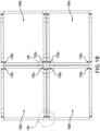
- disclosed node system 200 allows node horizontal and vertical chassis to be coupled to each other with only the top connecting parts 130 of each chassis 100 being exposed on the top 705 of an otherwise weather sealed chassis, such as shown in Fig. 7 which illustrates the top of four adjacent chassis prior to installation of the diaphragm plate 210.
- the nodes will define a rectangle having dimensions W by V.
- the diaphragm plate 210 which is used in this configuration will generally be a rectangle having dimensions W' by V' where W' is substantially equal to or less than W and V' is substantially equal to or less than V so that the entire top surface of the vertical supports will be covered.
- the vertical diaphragm plate could also be sitting in a recess rather than proud of the fireproofing and weatherproofing. Such a recess can be formed by using vertical supports 105 that do not extend fully to the top of the horizontal supports.
- the top of the chassis (apart from the top connecting parts) and any weather barrier formed on the top can remain undisturbed and the risk of water or other contaminants entering the interior of the chassis from the top reduced or avoided entirely.
- the entire assembly can be done from the top of each chassis. Workers are not required to access any internal portions of the chassis, thereby limiting the possibility for internal damage and reducing worker risk.
Landscapes
- Engineering & Computer Science (AREA)
- General Engineering & Computer Science (AREA)
- Architecture (AREA)
- Mechanical Engineering (AREA)
- Civil Engineering (AREA)
- Structural Engineering (AREA)
- Physics & Mathematics (AREA)
- Electromagnetism (AREA)
- Joining Of Building Structures In Genera (AREA)
- Coupling Device And Connection With Printed Circuit (AREA)
Claims (15)
- Verbindungssystem zur Verwendung beim Verbinden von vorgefertigten Gebäudemodulen miteinander, wobei das System Folgendes umfasst:einen Bolzen (215), aufweisend einen Kopf (216) mit einem Kopfdurchmesser und einen Schaft (217) mit einem Schaftdurchmesser;einen Koppler (205) mit einer Gewindeöffnung, die darin so bemessen ist, dass sie mittels Gewinde den Schaft des Bolzens aufnimmt; underste und zweite Stützelemente (105);wobei jedes jeweilige Stützelement (105) umfasst:wobei der erste Verbindungsteil (135-1) des ersten Stützelements (101) axial mit dem zweiten Verbindungsteil (130) des zweiten Stützelements (105) verbunden werden kann, indem der Bolzen (215) in die Bohrung in dem ersten Stützelement (410) über den zweiten Verbindungsteil des ersten Stützelements (130) eingeführt wird und der Bolzen gedreht wird, so dass der Schaft in die Gewindeöffnung in des Kopplers (205) eingreift, wenn der Koppler in der gefangenen Position innerhalb des axialen Lochs des zweiten Verbindungsteils des zweiten Stützelements (325) montiert ist.einen langgestreckten Hohlkörper, aufweisend eine Mittelachse (305), ein erstes und ein zweites Ende mit einer ersten bzw. einer zweiten Außenfläche, die im Wesentlichen senkrecht zu der Mittelachse stehen, einen Innenraum, ein erstes Verbindungsteil (135) an dem ersten Ende und ein zweites Verbindungsteil (130) an dem zweiten Ende;der erste Verbindungsteil (135) eine Bohrung (410) darin entlang der Mittelachse mit einer ersten Öffnung (415) angrenzend an das Innere und aufweisend einen ersten Durchmesser, eine zweite Öffnung (425) in der ersten Außenfläche und aufweisend einen zweiten Durchmesser, der kleiner als der erste Durchmesser ist, und eine Schulter (435) innerhalb der Bohrung zwischen der ersten Öffnung und der zweiten Öffnung aufweist, wobei der Kopfdurchmesser des Bolzens kleiner als der erste Durchmesser und größer als der zweite Durchmesser ist und der Schaftdurchmesser des Bolzens kleiner als der zweite Durchmesser ist, wobei der Bolzen teilweise durch die Bohrung hindurchgehen kann, wobei sich der Schaft davon wegführend erstreckt; undwobei der zweite Verbindungsteil (130) ein axiales Loch (325), das darin von der zweiten Außenfläche zum Inneren verläuft und einen Durchmesser aufweist, der durchweg größer ist als der Kopfdurchmesser des Bolzens, und eine nach innen gerichtete Schulter (340) darin aufweist, wobei das axiale Loch so konfiguriert ist, dass es dem Koppler (205) in einer Einführungsposition ermöglicht, von außerhalb des Körpers angrenzend an das zweite Ende durch das axiale Loch an der Schulter vorbei bewegt zu werden, und dass es eine Drehung des Kopplers innerhalb des axialen Lochs von der Einführungsposition in eine gefangene Position ermöglicht, in der die Schulter die Bewegung des Kopplers in Richtung des zweiten Endes blockiert;
- Verbindungssystem nach Anspruch 1, wobei für jedes jeweilige Stützelement das axiale Loch (325) in dem zweiten Teil einen ersten offenen Bereich (330) angrenzend an das zweite Ende definiert, in den der Koppler platziert werden kann, wenn er sich in der Einführungsposition befindet, und einen zweiten offenen Bereich (335) angrenzend an den ersten offenen Bereich, wobei der zweite offene Bereich so konfiguriert ist, dass er eine Drehung des Kopplers, wenn er sich in dem zweiten offenen Bereich befindet, von der Einführungsposition in die gefangene Position ermöglicht und wobei die Schulter (340), wenn in der gefangenen Position, die Entfernung des Kopplers aus dem zweiten offenen Bereich verhindert.
- Verbindungssystem nach Anspruch 2, wobei das Koppler (205) einen rechteckigen Querschnitt aufweist,für jedes jeweilige Stützelement (105) der langgestreckte Körper vier Außenseiten aufweist, die im Wesentlichen parallel zur Mittelachse verlaufen und einen rechteckigen Umfang definieren,der erste offene Bereich hat Innenseiten aufweist, die im Wesentlichen parallel zur Mittelachse verlaufen und einen rechteckigen offenen Bereich bilden, in den der Koppler eintreten kann;der rechteckige offene Bereich relativ zum rechteckigen Umfang um 15 bis 30 Grad gedreht ist.
- Verbindungssystem nach einem der Ansprüche 1 bis 3, wobei der zweite Verbindungsteil (130) für jedes jeweilige Stützelement (105) ferner ein erstes Kopplerverriegelungsloch (350) in der jeweiligen oberseitigen Oberfläche aufweist, das sich bis zu dem zweiten offenen Bereich hindurcherstreckt, wobei, wenn ein erster Verriegelungsstift (345) in das erste Kopplerverriegelungsloch eingeführt wird, der erste Verriegelungsstift die Drehung des Kopplers einschränkt, wenn sich der Koppler in der gefangenen Position innerhalb des zweiten offenen Bereichs befindet.
- Verbindungssystem nach Anspruch 1, wobei der erste Verbindungsteil für jedes jeweilige Stützelement (105) ferner mindestens eine Ausrichtungsöffnung (440) in der unterseitigen Oberfläche des ersten Verbindungsteils umfasst, die so konfiguriert ist, dass sie ein Ausrichtungselement (211) aufnimmt, das sich von einer allgemein ebenen Membranplatte (210) nach oben erstreckt, wenn der erste Verbindungsteil auf die Membranplatte abgesenkt wird.
- Verbindungssystem nach Anspruch 5 umfasst außerdem die Membranplatte;die Membranplatte (210) eine oberseitige Oberfläche aufweist, wobei sich das Ausrichtungselement (211) von dieser nach oben erstreckt und eine Bolzenöffnung (540) aufweist, die von der jeweiligen oberseitigen Oberfläche zu einer unterseitigen Oberfläche der Membranplatte verläuft und einen Durchmesser aufweist, der größer ist als der Schaftdurchmesser;wobei die Membranplatte zwischen dem ersten Verbindungsteil des ersten Stützelements und dem zweiten Verbindungsteil des zweiten Stützelements positioniert werden kann, wobei das Ausrichtungselement in die Ausrichtungsöffnung eingreift und die Bolzenöffnung axial mit der Mittelachse der ersten vertikalen Stütze und der Mittelachse der zweiten vertikalen Stütze ausgerichtet ist.
- Verbindungssystem nach Anspruch 5, wobei die Membranplatte (210) ein darin ausgebildetes Membranausrichtungsloch (545) aufweist und der Koppler ein darin ausgebildetes Kopplerausrichtungsloch (535) aufweist,
das Membranausrichtungsloch und das Kopplerausrichtungsloch auf der Membranplatte bzw. dem Koppler positioniert sind, so dass die Membranplatte, wenn sich der Koppler in der gefangenen Position im zweiten Verbindungsteil eines jeweiligen Stützelements befindet, über dem zweiten Verbindungsteil positioniert werden kann, wobei das Membranausrichtungsloch und das Kopplerausrichtungsloch axial ausgerichtet sind und die Bolzenöffnung axial mit dem axialen Loch im zweiten Verbindungsteil ausgerichtet ist. - Gebäudemodul mit einer Unterseite, einer Oberseite und einer Vielzahl von Verbindungssystemen nach einem der Ansprüche 1 bis 7, wobei das Stützelement jedes Verbindungssystems vertikal orientiert ist und sich von der Unterseite des Moduls zur Oberseite des Moduls erstreckt, wobei sich der erste Verbindungsteil an der Unterseite des Moduls und der zweite Verbindungsteil an der Oberseite des Moduls befindet.
- Verfahren zum Zusammenbau einer Struktur, das die folgenden Schritte umfasst:Bereitstellen einer Vielzahl von vorgefertigten Gebäudemodulen, wobei jedes Modul eine hohle vertikale Stütze (105) aufweist, wobei vertikal angrenzende Stützen unter Verwendung eines Bolzens (215) zusammengefügt werden können, aufweisend einen Gewindeschaft (217) mit einem Schaftdurchmesser und einem Kopf (216) mit einem Kopfdurchmesser, der größer als der Schaftdurchmesser ist,wobei jede vertikale Stütze (105) eine jeweilige Mittelachse (305), ein oberseitiges und ein unterseitiges Ende aufweist und umfassend (i) einen ersten Verbindungsteil (135) am unterseitigen Ende der jeweiligen vertikalen Stütze und mit einer Bohrung (410) darin entlang der Mittelachse und aufweisend eine erste Öffnung (415) mit einem Durchmesser, der größer als der Bolzenkopfdurchmesser ist und an ein Inneres der jeweiligen vertikalen Stütze angrenzt, und eine zweite Öffnung (425), die an den Boden der jeweiligen vertikalen Stütze angrenzt und einen Durchmesser aufweist, der größer als der Schaftdurchmesser, aber kleiner als der Bolzendurchmesser ist, wobei der Bolzen teilweise durch die Bohrung hindurchgehen kann, und (ii) einen zweiten Verbindungsteil (130) am oberseitigen Ende der vertikalen Stütze, wobei der zweite Verbindungsteil ein axiales Loch (325) aufweist, das von einer oberseitigen Oberfläche zu einer unterseitigen Oberfläche verläuft und einen Durchmesser aufweist, der durchgehend größer ist als der Kopfdurchmesser des Bolzens, und eine nach unten weisende Schulter (340) darin aufweist, wobei das axiale Loch so konfiguriert ist, dass es die Drehung eines Kopplers (205) um die zentrale Achse aus einer Einführungsposition in eine gefangene Position ermöglicht, wobei die Schulter das Entfernen des Kopplers blockiert;Platzieren eines ersten unteren Moduls;Befestigen eines ersten Kopplers in der gefangenen Position innerhalb des axialen Lochs im zweiten Verbindungsteil der vertikalen Stütze des ersten unteren Moduls, wobei der erste Koppler eine Gewindeöffnung darin aufweist;Platzieren eines ersten oberen Moduls über dem ersten unteren Modul, so dass die vertikale Stütze des ersten unteren Moduls und die vertikale Stütze des ersten oberen Moduls im Wesentlichen axial ausgerichtet sind;Einführen eines ersten Bolzens durch den zweiten Verbindungsteil der vertikalen Stütze des ersten oberen Moduls und in die Bohrung des ersten Verbindungsteils der vertikalen Stütze des ersten oberen Moduls, wobei sich der Schaft des Bolzens von dem ersten Verbindungsteil aus erstreckt, um in die erste Gewindeöffnung des Kopplers einzugreifen; undFestziehen des ersten Bolzens mit einem Schraubenschlüssel (515), der durch den zweiten Verbindungsteil der vertikalen Stütze des ersten oberen Moduls eingeführt wird.
- Verfahren nach Anspruch 9, das ferner vor dem Platzieren des ersten oberen Moduls die folgenden Schritte umfasst:Platzieren eines zweiten unteren Moduls horizontal neben dem ersten unteren Modul, so dass die jeweiligen vertikalen Stützen des ersten und zweiten unteren Moduls angrenzend liegen;Befestigen eines zweiten Kopplers in der gefangenen Position innerhalb des axialen Lochs im zweiten Verbindungsteil der vertikalen Stütze des zweiten unteren Moduls, wobei der zweite Koppler eine Gewindeöffnung darin aufweist;Platzieren einer Membranplatte (210) über die zweiten Verbindungsteilen der vertikalen Stützen des ersten und zweiten unteren Moduls; wobei die Membranplatte eine erste Bolzenöffnung (540), die mit der Gewindeöffnung des ersten Kopplers ausgerichtet ist, und eine zweite Bolzenöffnung (540) aufweist, die mit der Gewindeöffnung des zweiten Kopplers ausgerichtet ist.
- Verfahren nach Anspruch 10, das ferner den Schritt umfasst, dass vor dem Platzieren des ersten oberen Moduls die Membranplatte vorübergehend entweder (a) am zweiten Koppler oder (b) im zweiten Verbindungsteil der vertikalen Stütze des zweiten unteren Moduls befestigt wird.
- Verfahren nach Anspruch 11, wobei die Membranplatte (210) und der Koppler (205) jeweils Ausrichtungslöcher (545, 535) darin aufweisen, wobei der Schritt zum vorübergehenden Befestigen der Membranplatte das Einführen eines Verriegelungsbolzens (225) durch das Membranplattenausrichtungsloch und in das Kopplerausrichtungsloch umfasst.
- Verfahren nach einem der Ansprüche 10-12, wobei der Schritt zum vorübergehenden Befestigen der Membranplatte ferner die folgenden Schritte umfasst:vor dem Platzieren des ersten oberen Moduls, Einführen eines zweiten Bolzens durch die zweite Bolzenöffnung und in die Gewindeöffnung des zweiten Kopplers; undEntfernen des zweiten Bolzens nach dem Platzieren des ersten oberen Moduls.
- Verfahren nach Anspruch 12, wobei die Membranplatte (210) ein Ausrichtungselement (211) aufweist, das sich von dieser nach oben erstreckt, wobei der erste Verbindungsteil am unterseitigen Ende der vertikalen Stütze des ersten oberen Moduls eine unterseitige Oberfläche mit einer Ausrichtungsöffnung (440) darin aufweist;
der Schritt zum Platzieren des ersten oberen Moduls umfasst das Absenken des ersten oberen Moduls auf das erste untere Modul, so dass das Ausrichtungselement in die Ausrichtungsöffnung eingreift. - Verfahren nach Anspruch 9, das weiterhin die folgenden Schritte umfasst:Bereitstellen einer Hebeplatte (606) mit einer Hebeöse (610), die sich von dieser nach oben erstreckt;Befestigen der Hebeplatte in der gefangenen Position innerhalb der axialen Öffnung im zweiten Verbindungsteil der vertikalen Stütze des ersten oberen Moduls;Anheben des ersten oberen Moduls mittels eines mit der Hebeöse verbundenen Seils; undEntfernen der Hebeplatte nach dem Schritt zum Platzieren des ersten oberen Moduls.
Applications Claiming Priority (3)
| Application Number | Priority Date | Filing Date | Title |
|---|---|---|---|
| US202062971669P | 2020-02-07 | 2020-02-07 | |
| US16/987,641 US10907342B1 (en) | 2020-02-07 | 2020-08-07 | Connection node for modular building structures |
| PCT/US2021/070116 WO2021159141A1 (en) | 2020-02-07 | 2021-02-03 | Connection node for modular building structures |
Publications (3)
| Publication Number | Publication Date |
|---|---|
| EP4100583A1 EP4100583A1 (de) | 2022-12-14 |
| EP4100583A4 EP4100583A4 (de) | 2024-03-13 |
| EP4100583B1 true EP4100583B1 (de) | 2025-05-28 |
Family
ID=74260648
Family Applications (1)
| Application Number | Title | Priority Date | Filing Date |
|---|---|---|---|
| EP21750534.6A Active EP4100583B1 (de) | 2020-02-07 | 2021-02-03 | Verbindungsknoten für modulare gebäudestrukturen |
Country Status (5)
| Country | Link |
|---|---|
| US (1) | US10907342B1 (de) |
| EP (1) | EP4100583B1 (de) |
| AU (2) | AU2021217231B2 (de) |
| CA (1) | CA3166260C (de) |
| WO (1) | WO2021159141A1 (de) |
Families Citing this family (22)
| Publication number | Priority date | Publication date | Assignee | Title |
|---|---|---|---|---|
| KR102526136B1 (ko) * | 2013-02-22 | 2023-04-26 | 지-모듈러 홀딩, 인크. | 모듈 빌딩 유닛과, 상기 모듈 빌딩 유닛을 구성하고 수송하는 방법 |
| EP4733517A3 (de) * | 2015-08-14 | 2026-05-13 | Z-Modular Holding, Inc | Verbinder für ein modulares gebäude |
| US10233953B1 (en) * | 2017-04-13 | 2019-03-19 | The United States Of America As Represented By The Secretary Of The Navy | Connector for non-cylindrical composite tubing and methods for making the same |
| EP3978711B1 (de) * | 2019-05-29 | 2025-09-03 | IMAC Engineering Co., Ltd. | Verfahren zum bau einer anlage und anlage |
| US12312799B2 (en) * | 2019-08-06 | 2025-05-27 | Jgc Corporation | Module for separate conveyance, structure for plant, and method of constructing structure for plant |
| KR102286493B1 (ko) * | 2020-02-21 | 2021-08-05 | 김승일 | 조립식 기둥 조립체 |
| CN113279482B (zh) * | 2021-04-13 | 2022-03-08 | 青岛理工大学 | 一种模块建筑一体化连接装置及安装方法 |
| BR112023025411A2 (pt) * | 2021-06-04 | 2024-02-20 | Andrew Tuohey | Centro de processamento de dados, método de montagem de um centro de processamento de dados e módulo de equipamento pré-fabricado |
| US12338617B2 (en) | 2021-07-02 | 2025-06-24 | Blokable, Llc | Resilient connector and methods of use of same |
| CZ309779B6 (cs) * | 2021-09-02 | 2023-10-04 | Univerzita Karlova | Modulární konstrukční spojka pro spojování konstrukčních profilů do nosných koster různých tvarů |
| CN114045939B (zh) * | 2021-11-11 | 2024-05-17 | 重庆大学 | 一种适合拼接全装修房间单元的箱体间快速拼接节点构造 |
| US20260125899A1 (en) * | 2022-02-28 | 2026-05-07 | Quality Electrical Systems, Inc. | End wall system for portable electrical buildings |
| US12247391B2 (en) * | 2022-04-24 | 2025-03-11 | ANC Capital Inc. | Concrete void form and method of modular construction therewith |
| USD1106508S1 (en) * | 2022-06-14 | 2025-12-16 | Spacecube IP Pty Ltd | Construction element |
| GB202208827D0 (en) * | 2022-06-15 | 2022-07-27 | City Univ Of London | Connector |
| US12490686B2 (en) | 2022-08-30 | 2025-12-09 | Toan Phan | Bracket system for attaching a cantilevered pergola to a roof rafter |
| US11566415B1 (en) * | 2022-08-30 | 2023-01-31 | Toan Phan | Bracket system for attaching a cantilevered pergola to a roof rafter |
| CN115450326B (zh) * | 2022-10-27 | 2024-04-26 | 中南大学 | 一种顶推滑块式可拆装模块钢结构节点及其施工方法 |
| US20250270804A1 (en) * | 2024-02-22 | 2025-08-28 | Onx, Inc. | Method and arrangement for coupling a foundation structure and a vertical precast structure |
| WO2025196737A1 (pt) * | 2024-03-22 | 2025-09-25 | Domingos Da Silva Teixeira S.A. | Sistema de conexão de um sistema construtivo e respetivo método de montagem |
| CN118242351B (zh) * | 2024-05-27 | 2024-07-19 | 四川博科斯电力科技有限公司 | 一种法兰拼接式模块化复合材料电杆的螺栓移位监测装置 |
| CN119686453B (zh) * | 2025-01-03 | 2025-10-17 | 中国能源建设集团山西省电力勘测设计院有限公司 | 一种模块化建筑结构插销自锁式连接节点 |
Family Cites Families (19)
| Publication number | Priority date | Publication date | Assignee | Title |
|---|---|---|---|---|
| US3563581A (en) * | 1969-09-29 | 1971-02-16 | Michael Sommerstein | Joint for structural assemblies |
| ZA761548B (en) * | 1976-03-12 | 1977-10-26 | Serbert Ind Ltd | Connector |
| DE2704954A1 (de) * | 1977-02-07 | 1978-08-10 | Otto Prof Dipl Ing D Jungbluth | Raeumliches tragwerk aus staeben und knotenkoerpern |
| DE3784083D1 (de) * | 1986-03-13 | 1993-03-25 | Braden Christopher Godden | Fachwerk-verbinder. |
| US4758111A (en) * | 1986-11-21 | 1988-07-19 | Michael Vitta | Protective enclosures |
| US5860258A (en) | 1997-06-09 | 1999-01-19 | Faith; William C. | Modular building |
| JP2001107467A (ja) * | 1999-10-05 | 2001-04-17 | Aizemu:Kk | 建物ユニットの接合構造 |
| US6390719B1 (en) * | 2000-02-29 | 2002-05-21 | Chun Jin Co., Ltd. | Joint of a supporting frame |
| JP2001254445A (ja) * | 2000-03-10 | 2001-09-21 | Sekisui Chem Co Ltd | ユニット建物の上下接合構造 |
| JP6141336B2 (ja) * | 2012-02-23 | 2017-06-07 | リー,ジュング−イョップ | 組立式建築物用六面体ユニット及び前記六面体ユニットの組立方法 |
| KR102526136B1 (ko) * | 2013-02-22 | 2023-04-26 | 지-모듈러 홀딩, 인크. | 모듈 빌딩 유닛과, 상기 모듈 빌딩 유닛을 구성하고 수송하는 방법 |
| AU2015252722B2 (en) | 2014-04-30 | 2019-09-26 | Z-Modular Holding, Inc. | Structural modular building connector |
| KR101579686B1 (ko) * | 2014-06-27 | 2015-12-22 | 권철진 | 프레임 결합블록 |
| WO2016165022A1 (en) | 2015-04-15 | 2016-10-20 | Vectorbloc Corp. | Connector for modular building structure |
| EP4733517A3 (de) * | 2015-08-14 | 2026-05-13 | Z-Modular Holding, Inc | Verbinder für ein modulares gebäude |
| EP3449064A4 (de) * | 2016-04-29 | 2019-12-11 | Rbon Holdings Pty Ltd | Modulare trägerstruktur und modulare sockelstruktur |
| JP6275798B1 (ja) * | 2016-10-18 | 2018-02-07 | 株式会社シェルター | 接合金物 |
| ES2670471B1 (es) * | 2016-11-30 | 2019-03-07 | Sustainable Energy&Housing S L | Conjunto de anclaje y unión para construcciones modulares |
| MX2019008532A (es) | 2017-01-19 | 2019-12-02 | Vectorbloc Corp | Conector de construcción modular. |
-
2020
- 2020-08-07 US US16/987,641 patent/US10907342B1/en active Active
-
2021
- 2021-02-03 WO PCT/US2021/070116 patent/WO2021159141A1/en not_active Ceased
- 2021-02-03 EP EP21750534.6A patent/EP4100583B1/de active Active
- 2021-02-03 CA CA3166260A patent/CA3166260C/en active Active
- 2021-02-03 AU AU2021217231A patent/AU2021217231B2/en active Active
-
2022
- 2022-11-24 AU AU2022275488A patent/AU2022275488B2/en active Active
Also Published As
| Publication number | Publication date |
|---|---|
| AU2021217231B2 (en) | 2022-09-01 |
| EP4100583A1 (de) | 2022-12-14 |
| AU2022275488A1 (en) | 2023-01-05 |
| CA3166260A1 (en) | 2021-08-12 |
| AU2022275488B2 (en) | 2024-10-31 |
| CA3166260C (en) | 2024-04-02 |
| AU2021217231A1 (en) | 2022-08-18 |
| US10907342B1 (en) | 2021-02-02 |
| WO2021159141A1 (en) | 2021-08-12 |
| EP4100583A4 (de) | 2024-03-13 |
Similar Documents
| Publication | Publication Date | Title |
|---|---|---|
| US10907342B1 (en) | Connection node for modular building structures | |
| US12129645B2 (en) | Connection node for modular building structures | |
| JP7507805B2 (ja) | モジュール式建物用コネクタ | |
| JP7289048B2 (ja) | 構造的なモジュール式建物のコネクタ | |
| CN108360683B (zh) | 组合式建筑单元以及建造和运输组合式建筑单元的方法 | |
| US8307605B2 (en) | Dome kit, structure and method | |
| US12480302B2 (en) | Connection node for modular building structures | |
| US20240426096A1 (en) | Universal modular connector | |
| US11913218B2 (en) | Modular construction connection mechanism | |
| JPH03262855A (ja) | 壁パネルの支持機構 | |
| WO2024058728A1 (en) | Modular building connection system | |
| TR2024020621T2 (tr) | Modüler yapi bağlanti si̇stemi̇ | |
| AU2011229148A1 (en) | Unitised building system |
Legal Events
| Date | Code | Title | Description |
|---|---|---|---|
| STAA | Information on the status of an ep patent application or granted ep patent |
Free format text: STATUS: THE INTERNATIONAL PUBLICATION HAS BEEN MADE |
|
| PUAI | Public reference made under article 153(3) epc to a published international application that has entered the european phase |
Free format text: ORIGINAL CODE: 0009012 |
|
| STAA | Information on the status of an ep patent application or granted ep patent |
Free format text: STATUS: REQUEST FOR EXAMINATION WAS MADE |
|
| 17P | Request for examination filed |
Effective date: 20220727 |
|
| AK | Designated contracting states |
Kind code of ref document: A1 Designated state(s): AL AT BE BG CH CY CZ DE DK EE ES FI FR GB GR HR HU IE IS IT LI LT LU LV MC MK MT NL NO PL PT RO RS SE SI SK SM TR |
|
| DAV | Request for validation of the european patent (deleted) | ||
| DAX | Request for extension of the european patent (deleted) | ||
| REG | Reference to a national code |
Ref country code: HK Ref legal event code: DE Ref document number: 40084888 Country of ref document: HK |
|
| A4 | Supplementary search report drawn up and despatched |
Effective date: 20240213 |
|
| RIC1 | Information provided on ipc code assigned before grant |
Ipc: E04B 1/35 20060101ALI20240207BHEP Ipc: E04B 1/348 20060101ALI20240207BHEP Ipc: E04G 21/14 20060101ALI20240207BHEP Ipc: F16B 12/30 20060101ALI20240207BHEP Ipc: F16B 12/40 20060101ALI20240207BHEP Ipc: F16B 45/00 20060101ALI20240207BHEP Ipc: F16B 7/04 20060101ALI20240207BHEP Ipc: F16B 7/18 20060101ALI20240207BHEP Ipc: F16B 9/00 20060101ALI20240207BHEP Ipc: E04B 1/24 20060101AFI20240207BHEP |
|
| GRAP | Despatch of communication of intention to grant a patent |
Free format text: ORIGINAL CODE: EPIDOSNIGR1 |
|
| STAA | Information on the status of an ep patent application or granted ep patent |
Free format text: STATUS: GRANT OF PATENT IS INTENDED |
|
| INTG | Intention to grant announced |
Effective date: 20241223 |
|
| GRAS | Grant fee paid |
Free format text: ORIGINAL CODE: EPIDOSNIGR3 |
|
| GRAA | (expected) grant |
Free format text: ORIGINAL CODE: 0009210 |
|
| STAA | Information on the status of an ep patent application or granted ep patent |
Free format text: STATUS: THE PATENT HAS BEEN GRANTED |
|
| AK | Designated contracting states |
Kind code of ref document: B1 Designated state(s): AL AT BE BG CH CY CZ DE DK EE ES FI FR GB GR HR HU IE IS IT LI LT LU LV MC MK MT NL NO PL PT RO RS SE SI SK SM TR |
|
| REG | Reference to a national code |
Ref country code: GB Ref legal event code: FG4D |
|
| REG | Reference to a national code |
Ref country code: CH Ref legal event code: EP |
|
| REG | Reference to a national code |
Ref country code: IE Ref legal event code: FG4D Ref country code: DE Ref legal event code: R096 Ref document number: 602021031452 Country of ref document: DE |
|
| REG | Reference to a national code |
Ref country code: DE Ref legal event code: R081 Ref document number: 602021031452 Country of ref document: DE Owner name: PALM DREAMSCAPES QOZB, LLC, AUSTIN, US Free format text: FORMER OWNER: ASSEMBLY OSM, INC., NEW YORK, NY, US |
|
| REG | Reference to a national code |
Ref country code: NL Ref legal event code: MP Effective date: 20250528 |
|
| RAP2 | Party data changed (patent owner data changed or rights of a patent transferred) |
Owner name: PALM DREAMSCAPES QOZB, LLC |
|
| PG25 | Lapsed in a contracting state [announced via postgrant information from national office to epo] |
Ref country code: ES Free format text: LAPSE BECAUSE OF FAILURE TO SUBMIT A TRANSLATION OF THE DESCRIPTION OR TO PAY THE FEE WITHIN THE PRESCRIBED TIME-LIMIT Effective date: 20250528 Ref country code: FI Free format text: LAPSE BECAUSE OF FAILURE TO SUBMIT A TRANSLATION OF THE DESCRIPTION OR TO PAY THE FEE WITHIN THE PRESCRIBED TIME-LIMIT Effective date: 20250528 |
|
| REG | Reference to a national code |
Ref country code: LT Ref legal event code: MG9D |
|
| PG25 | Lapsed in a contracting state [announced via postgrant information from national office to epo] |
Ref country code: NO Free format text: LAPSE BECAUSE OF FAILURE TO SUBMIT A TRANSLATION OF THE DESCRIPTION OR TO PAY THE FEE WITHIN THE PRESCRIBED TIME-LIMIT Effective date: 20250828 Ref country code: GR Free format text: LAPSE BECAUSE OF FAILURE TO SUBMIT A TRANSLATION OF THE DESCRIPTION OR TO PAY THE FEE WITHIN THE PRESCRIBED TIME-LIMIT Effective date: 20250829 |
|
| PG25 | Lapsed in a contracting state [announced via postgrant information from national office to epo] |
Ref country code: PL Free format text: LAPSE BECAUSE OF FAILURE TO SUBMIT A TRANSLATION OF THE DESCRIPTION OR TO PAY THE FEE WITHIN THE PRESCRIBED TIME-LIMIT Effective date: 20250528 Ref country code: NL Free format text: LAPSE BECAUSE OF FAILURE TO SUBMIT A TRANSLATION OF THE DESCRIPTION OR TO PAY THE FEE WITHIN THE PRESCRIBED TIME-LIMIT Effective date: 20250528 |
|
| REG | Reference to a national code |
Ref country code: GB Ref legal event code: 732E Free format text: REGISTERED BETWEEN 20250918 AND 20250924 |
|
| PG25 | Lapsed in a contracting state [announced via postgrant information from national office to epo] |
Ref country code: BG Free format text: LAPSE BECAUSE OF FAILURE TO SUBMIT A TRANSLATION OF THE DESCRIPTION OR TO PAY THE FEE WITHIN THE PRESCRIBED TIME-LIMIT Effective date: 20250528 |
|
| PG25 | Lapsed in a contracting state [announced via postgrant information from national office to epo] |
Ref country code: HR Free format text: LAPSE BECAUSE OF FAILURE TO SUBMIT A TRANSLATION OF THE DESCRIPTION OR TO PAY THE FEE WITHIN THE PRESCRIBED TIME-LIMIT Effective date: 20250528 |
|
| PG25 | Lapsed in a contracting state [announced via postgrant information from national office to epo] |
Ref country code: RS Free format text: LAPSE BECAUSE OF FAILURE TO SUBMIT A TRANSLATION OF THE DESCRIPTION OR TO PAY THE FEE WITHIN THE PRESCRIBED TIME-LIMIT Effective date: 20250828 |
|
| PG25 | Lapsed in a contracting state [announced via postgrant information from national office to epo] |
Ref country code: IS Free format text: LAPSE BECAUSE OF FAILURE TO SUBMIT A TRANSLATION OF THE DESCRIPTION OR TO PAY THE FEE WITHIN THE PRESCRIBED TIME-LIMIT Effective date: 20250928 |
|
| PG25 | Lapsed in a contracting state [announced via postgrant information from national office to epo] |
Ref country code: LV Free format text: LAPSE BECAUSE OF FAILURE TO SUBMIT A TRANSLATION OF THE DESCRIPTION OR TO PAY THE FEE WITHIN THE PRESCRIBED TIME-LIMIT Effective date: 20250528 |
|
| REG | Reference to a national code |
Ref country code: AT Ref legal event code: MK05 Ref document number: 1798675 Country of ref document: AT Kind code of ref document: T Effective date: 20250528 |
|
| PG25 | Lapsed in a contracting state [announced via postgrant information from national office to epo] |
Ref country code: SM Free format text: LAPSE BECAUSE OF FAILURE TO SUBMIT A TRANSLATION OF THE DESCRIPTION OR TO PAY THE FEE WITHIN THE PRESCRIBED TIME-LIMIT Effective date: 20250528 Ref country code: AT Free format text: LAPSE BECAUSE OF FAILURE TO SUBMIT A TRANSLATION OF THE DESCRIPTION OR TO PAY THE FEE WITHIN THE PRESCRIBED TIME-LIMIT Effective date: 20250528 Ref country code: DK Free format text: LAPSE BECAUSE OF FAILURE TO SUBMIT A TRANSLATION OF THE DESCRIPTION OR TO PAY THE FEE WITHIN THE PRESCRIBED TIME-LIMIT Effective date: 20250528 |
|
| PG25 | Lapsed in a contracting state [announced via postgrant information from national office to epo] |
Ref country code: CZ Free format text: LAPSE BECAUSE OF FAILURE TO SUBMIT A TRANSLATION OF THE DESCRIPTION OR TO PAY THE FEE WITHIN THE PRESCRIBED TIME-LIMIT Effective date: 20250528 |
|
| PG25 | Lapsed in a contracting state [announced via postgrant information from national office to epo] |
Ref country code: EE Free format text: LAPSE BECAUSE OF FAILURE TO SUBMIT A TRANSLATION OF THE DESCRIPTION OR TO PAY THE FEE WITHIN THE PRESCRIBED TIME-LIMIT Effective date: 20250528 |
|
| PG25 | Lapsed in a contracting state [announced via postgrant information from national office to epo] |
Ref country code: SK Free format text: LAPSE BECAUSE OF FAILURE TO SUBMIT A TRANSLATION OF THE DESCRIPTION OR TO PAY THE FEE WITHIN THE PRESCRIBED TIME-LIMIT Effective date: 20250528 |
|
| REG | Reference to a national code |
Ref country code: DE Ref legal event code: R097 Ref document number: 602021031452 Country of ref document: DE |
|
| PLBE | No opposition filed within time limit |
Free format text: ORIGINAL CODE: 0009261 |
|
| STAA | Information on the status of an ep patent application or granted ep patent |
Free format text: STATUS: NO OPPOSITION FILED WITHIN TIME LIMIT |
|
| PGFP | Annual fee paid to national office [announced via postgrant information from national office to epo] |
Ref country code: GB Payment date: 20260223 Year of fee payment: 6 |
|
| REG | Reference to a national code |
Ref country code: CH Ref legal event code: L10 Free format text: ST27 STATUS EVENT CODE: U-0-0-L10-L00 (AS PROVIDED BY THE NATIONAL OFFICE) Effective date: 20260409 |
|
| PGFP | Annual fee paid to national office [announced via postgrant information from national office to epo] |
Ref country code: DE Payment date: 20260220 Year of fee payment: 6 |
|
| PGFP | Annual fee paid to national office [announced via postgrant information from national office to epo] |
Ref country code: IT Payment date: 20260203 Year of fee payment: 6 |
|
| PGFP | Annual fee paid to national office [announced via postgrant information from national office to epo] |
Ref country code: FR Payment date: 20260227 Year of fee payment: 6 |
|
| 26N | No opposition filed |
Effective date: 20260303 |