EP4100551B1 - Verfahren und vorrichtung zum granulieren von aus eisen und stahl stammender schlacke - Google Patents
Verfahren und vorrichtung zum granulieren von aus eisen und stahl stammender schlacke Download PDFInfo
- Publication number
- EP4100551B1 EP4100551B1 EP21709095.0A EP21709095A EP4100551B1 EP 4100551 B1 EP4100551 B1 EP 4100551B1 EP 21709095 A EP21709095 A EP 21709095A EP 4100551 B1 EP4100551 B1 EP 4100551B1
- Authority
- EP
- European Patent Office
- Prior art keywords
- slag
- flow
- granules
- drops
- gas
- Prior art date
- Legal status (The legal status is an assumption and is not a legal conclusion. Google has not performed a legal analysis and makes no representation as to the accuracy of the status listed.)
- Active
Links
Images


Classifications
-
- C—CHEMISTRY; METALLURGY
- C21—METALLURGY OF IRON
- C21B—MANUFACTURE OF IRON OR STEEL
- C21B3/00—General features in the manufacture of pig-iron
- C21B3/04—Recovery of by-products, e.g. slag
- C21B3/06—Treatment of liquid slag
- C21B3/08—Cooling slag
-
- C—CHEMISTRY; METALLURGY
- C21—METALLURGY OF IRON
- C21B—MANUFACTURE OF IRON OR STEEL
- C21B2400/00—Treatment of slags originating from iron or steel processes
- C21B2400/02—Physical or chemical treatment of slags
- C21B2400/022—Methods of cooling or quenching molten slag
- C21B2400/026—Methods of cooling or quenching molten slag using air, inert gases or removable conductive bodies
-
- C—CHEMISTRY; METALLURGY
- C21—METALLURGY OF IRON
- C21B—MANUFACTURE OF IRON OR STEEL
- C21B2400/00—Treatment of slags originating from iron or steel processes
- C21B2400/05—Apparatus features
- C21B2400/062—Jet nozzles or pressurised fluids for cooling, fragmenting or atomising slag
-
- Y—GENERAL TAGGING OF NEW TECHNOLOGICAL DEVELOPMENTS; GENERAL TAGGING OF CROSS-SECTIONAL TECHNOLOGIES SPANNING OVER SEVERAL SECTIONS OF THE IPC; TECHNICAL SUBJECTS COVERED BY FORMER USPC CROSS-REFERENCE ART COLLECTIONS [XRACs] AND DIGESTS
- Y02—TECHNOLOGIES OR APPLICATIONS FOR MITIGATION OR ADAPTATION AGAINST CLIMATE CHANGE
- Y02W—CLIMATE CHANGE MITIGATION TECHNOLOGIES RELATED TO WASTEWATER TREATMENT OR WASTE MANAGEMENT
- Y02W30/00—Technologies for solid waste management
- Y02W30/50—Reuse, recycling or recovery technologies
Definitions
- the present invention relates to a process for the granulation of slag deriving from iron and steel production, in particular a process for the dry granulation of slag, in addition to an apparatus suitable for implementing this process.
- the process and apparatus according to the present invention allow the production of granulates with different characteristics depending on the intended use, thus proving to be particularly versatile.
- iron and steel processes for the production of cast iron and steel generate significant quantities of slag whose composition is closely related to the characteristics of the raw materials and additive elements used in the process.
- the slag will have different chemical and physical characteristics.
- the slag is classified, based on the regulations currently in force such as Regulation (EC) Nr. 1907/2006 relating to the registration, evaluation, authorization and restriction of chemical substances (REACH), according to these chemical and physical characteristics.
- EC Regulation
- REACH authorization and restriction of chemical substances
- some types of slag are recognized as by-products, however they are much more often considered as being waste to be disposed of, and therefore represent a serious problem from both an environmental and logistical point of view.
- the slag produced by ladle refining furnaces undergoes a transformation of the crystal lattice which leads to the formation of a fine and dusty material, which greatly complicates environmental and logistical management.
- One of the techniques used is granulation with water or dry granulation.
- Dry granulation where possible, is preferable to that with water as it avoids the consumption of water and reduces the need for treatment.
- This method however has various drawbacks, and in particular is anything but versatile, not allowing granulated slag having different physical characteristics to be obtained.
- the required characteristics are different (when the slag is used, for example, as an inert product in the civil field, it is preferable that the morphological structure be predominantly amorphous, i.e. vitreous, whereas in the case of other uses, for example when used as a binder, the granulate must have a predominantly crystalline structure, possibly after grinding), the need is felt in the field for having a flexible plant, which allows a flexible granulation process to be implemented so as to be able to produce granulates with different characteristics depending on the intended use.
- the undertaking of the present invention is to provide a dry granulation process of slag generated by iron and steel processes which is particularly flexible so as to be able to obtain granulates with different physical characteristics, allowing these granulates to be destined for different end-uses.
- the objective of the present invention is also to provide an apparatus for the dry granulation of slag generated by iron and steel processes capable of implementing this process.
- the objective of the present invention is to provide a process and an apparatus that allow controlled dry granulations to be effected, so as to be able to vary the cooling rate of the slag and thus obtain physically different granular structures.
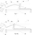
- the apparatus 1 for the dry granulation of molten slag S in particular molten slag generated by iron and steel processes, comprises at least one container 10 containing the molten slag in the liquid state S to be treated, means for generating a flow of gas 20 for the generation of a flow 25 of gas (or mixture of gases, for example air under ambient conditions) suitable for enveloping the flow Q of slag S when this is spilled from said container 10 before said flow Q comes into contact with other parts of the apparatus, breaking the flow Q of slag S into small drops and pushing these drops of said flow Q of slag S along a trajectory having at least one component along the longitudinal direction L away from said means for generating an air flow 20 and from said container 10.
- a flow of gas 20 for the generation of a flow 25 of gas (or mixture of gases, for example air under ambient conditions) suitable for enveloping the flow Q of slag S when this is spilled from said container 10 before said flow Q comes into contact with other parts of the apparatus, breaking the flow
- LF/secondary metallurgy slag that is spilled or tapped from the container or ladle is very often mixed with a far from negligible part of liquid metal (liquid steel), which, when it falls onto the granulator roller, damages it very rapidly, unacceptably shortening the useful life of the roller and making the process generally unusable.
- the container 10 can, by way of example, be a ladle (i.e. a metal carpentry vessel internally lined with refractory material) or a cauldron (cast iron vessel with or without internal refractory).
- a ladle i.e. a metal carpentry vessel internally lined with refractory material
- a cauldron cast iron vessel with or without internal refractory
- the apparatus 1 also comprises means 30 for collecting and transporting the cooled slag granules and means for deflecting and/or stopping 40 said flow Q of slag S in order to obtain slag granules having desired morphological characteristics.
- the apparatus 1 for the dry granulation of slag S object of the present invention is suitable for implementing a dry granulation process also object of the present invention, which is characterized in that it comprises at least one step consisting in controlling and modifying the time and/or cooling rate of the drops/granules of the flow Q of slag S in order to obtain slag granules having the desired morphological characteristics, with the consequent advantages illustrated above.
- the step for controlling and modifying the time and/or the cooling rate of said drops/granules of said flow Q of slag S preferably comprises at least one step consisting in controlling and modifying the residence time in flight of said droplets/granules driven by said jet of gas 25 which directly strikes the flow Q spilled from said container 10, deflecting and/or stopping its movement, by means of deflection and/or stopping means 40 of said flow Q.
- Said deflection and/or stopping means 40 of said flow in drops/granules Q of slag S are configured for intercepting said flow Q and causing the precipitation of said slag granules S in said means 30 for collecting and transporting the cooled slag granules.
- the deflection and/or stopping means of the flow of slag comprise at least a plate or a panel 40 positioned in a point of the component along the longitudinal direction L of the trajectory of the flow in drops/granules Q of slag S pushed by the gas jet 25.
- Said plate or panel 40 are movable along said longitudinal direction L so as to be able to vary the residence time in flight of the granules of the flow in flight Q by positioning said plate or panel 40 in different points of the flight path of said drops/granules which will consequently be precipitated into the collection means 30 after a cooling period in flight which can be controlled and varied by the operator according to where he positions the plate or panel 40.
- Non-limiting examples of the collection and transporting means 30 can be systems such as vibrating or oscillating conveyors, such as vibro-extractors, or those with plates.
- the collection and transporting means 30 can consist for example of a rotating and tilted drum which transports the granulate by gravity.
- the collection and transporting means 30, rather than being of the continuous type such as those mentioned, can be of the "batch" type, such as for example collection bins which can be moved by forklifts or other systems.
- FIG. 2 This type of apparatus capable of effecting the dry granulation of slag is shown in figure 2 , where possible trajectories A and B are schematically illustrated, followed by the drops of spilled molten slag which are pushed by the flow of gas 25.
- the graph of figure 3 shows the cooling curves C A and C B respectively of the particles following the trajectory A and those following the trajectory B, all starting from the initial temperature T 0 which can be assumed as being equal to or close to the extraction value of the slag S from the furnace (around 1,500°C - 1,600°C).
- a pair of values of time t N and temperature T N can be identified, which can be considered as discriminating the result that will be obtained at the structure level of the solid granule: if the temperature T N is reached in a time less than t N , then the structure of the solid will be predominantly amorphous; if on the other hand the temperature T N is reached in a time higher than t N , then the structure of the solid will be at least partly crystalline.
- the apparatus according to the present invention allows a process to be implemented wherein the cooling rate of the slag is controlled and can be varied, consequently allowing the physical structure of the solid granule obtained to be controlled.
- the apparatus 1 is characterized in that it further comprises deflection and/or stopping means 40 of said flow in drops/granules Q of slag S configured so as to intercept said flow Q and cause the precipitation of said slag granules S in said collection and transporting system 30 for collecting and transporting the cooled slag granules.
- Said apparatus therefore implements a process, also object of the present invention, wherein the time and/or the cooling rate of said drops/granules of said flow Q of slag S can be controlled and modified in order to obtain slag granules having the desired morphological characteristics.
- the speed of the jet 25 of gas or gas mixture is normally around 50-150 m/s, depending on the size of the granules to be produced (the higher the speed, the smaller the slag granules produced will be) .
- the mass flow-rate of gas (advantageously air) is regulated so as to have a pulse which is such as to break the slag flow and project the drops thus formed along parabolic trajectories away from the interaction point between slag flow and gas jet; in particular, the ratio between the flow-rates of the gas jet 25 and the slag flow can preferably range from 0.5 to 2 (kg/s of gas over kg/s of slag).
- the slag particles can follow, for example, a similar trajectory to that indicated with A in figure 2 , which corresponds to a cooling curve such as that indicated by C A in figure 3 : the particles that travel along this trajectory have a flight time which is such as to guarantee a rapid and complete cooling of the solid, so as to maintain almost all of the amorphous structure in the granule formed.
- the trajectory followed by the slag particles could be that indicated with B in figure 2 , therefore a much shorter path in the air with respect to case A previously considered: in this case, the cooling curve follows a different trend, represented by the curve C B in figure 3 . After cooling in air substantially similar to that of case A, the solidified slag particle reaches the ground when it is still at a high temperature.
- this will comprise means 40 for deflecting and/or stopping the flow in drops/granules Q of slag S movable along said longitudinal direction L and blockable in a desired position.
- the granules propelled by the gas jet 25 therefore travel along a parabolic section in the air, cooling rapidly, until they reach said deflection and/or stopping means 40 which interrupt or in any case divert their flight; following the impact against the element 40, the granules precipitate downwards, creating a layer having a certain thickness on the transporting system 30, which conveys them towards subsequent processing (this thickness is substantially correlated to the speed of the transporting system and to the flow-rate of the granules generated, in turn correlated to the flow-rate of the slag spilled from the container 10 ).
- said deflection and/or stopping means 40 of said flow in drops/granules Q of slag S advantageously comprise at least one plate or panel 40 comprising at least one impact surface 40c configured for deflecting and/or stopping the flow in drops/granules Q of slag S and cause the precipitation of said slag granules S in a predetermined area of said collection and transporting means 30.
- said at least one plate or panel 40 can be rotated around a substantially horizontal axis A so as to be able to modify the inclination of the impact surface 40c of said plate or panel 40 with respect to the vertical direction and can be blocked in a desired position so as to be able to modify the trajectory and falling point of the granules of said flow Q deviated from said impact surface 40c within a predetermined area of the collection and transporting system 30.
- a plurality of said deflection and/or stopping means 40 of said flow in drops/granules Q of slag S can be provided, positioned along said longitudinal direction L, each of which can be moved, independently of each other, between a first non-operating position in which they do not intercept the flow in drops/granules Q of said slag S and an operating position in which they intercept the flow in drops/granules Q of said slag S.
- Said plurality of deflection and/or stopping means 40 of said flow can therefore advantageously comprise at least two plates or panels 40a, 40b each of said plates or panels 40a, 40b being movable, independently of each other, between a first position which is not operational (for example the right panel 40b in figure 6 and the left panel 40a in figure 6 bis) in which it does not intercept the flow in drops/granules Q of said slag S, and an operating position (for example the first panel 40a on the left in figure 6 and the second panel 40b on the right in figure 6 bis) in which they intercept the flow in drops/granules Q of said slag S.
- a first position which is not operational for example the right panel 40b in figure 6 and the left panel 40a in figure 6 bis
- an operating position for example the first panel 40a on the left in figure 6 and the second panel 40b on the right in figure 6 bis
- the container 10 and the means 20 for generating a gas flow 25 are mounted on a supporting structure 60, said structure being equipped with means 61 which allow it to move at least along a direction parallel to that of the gas flow 25.
- the container 10 can be advantageously overturned in a controlled manner by acting on actuators 62 of the known type (for example hydraulic actuators or other types of actuator, electric motors, etc.).
- the deflection and/or stopping means 40 consist of a wall which has an impact surface 40c towards which the flow Q of drops/granules of said slag S is projected.
- the wall 40 is fixed or movable; furthermore, it can advantageously be made of metallic material with a high resistance to shock and wear, and equipped with cooling systems.
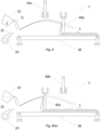
- the apparatus 1 for the dry granulation of slag S can advantageously comprise a collection and transporting system 30 in turn comprising a drum 31 rotating around its own longitudinal axis so as to transport the granulate, moving it away from the granulation area of the slag underlying said plate or panel 40, the latter being supported and moved along the longitudinal direction L by a movable supporting element 41 suitable for translating inside said drum 31 with respect to the latter.
- a collection and transporting system 30 in turn comprising a drum 31 rotating around its own longitudinal axis so as to transport the granulate, moving it away from the granulation area of the slag underlying said plate or panel 40, the latter being supported and moved along the longitudinal direction L by a movable supporting element 41 suitable for translating inside said drum 31 with respect to the latter.
- the container 10 for example, a cauldron or a ladle
- the container 10 pours a first stream Q' of slag S into an additional granulation container 150.
- This granulation container 150 can be internally lined with refractory material and heated, so as to effectively control the temperature of the slag to be treated.
- the granulation container 150 is in turn suitable for the controlled discharging of a second flow Q of slag S destined for being struck by the jet of air (or gas) 25: it can be configured for example as a "tundish" (tundish/ingot mould) which remains fixed and is equipped with an adjustable duct 160 for discharging the slag, or it can be composed, for example, of a ladle lined with refractory material and equipped with a casting spout, mounted on an overturning system suitable for controlling the flow-rate of the slag leaving the container itself.
- the granulation container 150 in addition to ensuring a constant temperature and consequently a constant viscosity of the slag contained therein, substantially allows the processes upstream in which the slag is generated (batch processes in fact), to be decoupled from the granulation process, which can consequently be operated in an almost continuous and independent manner, with a considerable saving on the plant design of various auxiliary pieces of equipment.
- the flow Q of slag leaving the granulation container 150 can usefully acquire an enlarged shape, for example on the basis of the conformation of the adjustable duct 160, or on the basis of the same shape of the granulation container 150, if it is used for spilling (for example through a pouring spout) the slag directly by means of controlled overturning: in other words, it can be convenient to generate a flow Q of slag with a section having a prevalent dimension in the transverse direction and a smaller dimension in the longitudinal direction. This enlarged conformation of the slag flow can favour the subsequent granulation step.
- this can consist of one or more compressors or fans, for example of the centrifugal type, suitable for generating a jet of gas or mixture of gases 25 directed towards the flow Q of slag coming from the granulation container 150.
- the gas can be air for example.
- the means 20 for generating the gas flow 25 can comprise an apparatus for distributing and dividing the flow-rate supplied by said one or more compressors or fans.
- these are preferably composed of a conveyor of the vibrating or oscillating type, known for example for applications in the same field for the supply and loading step of the charge materials into the electric arc furnace such as for example ferrous scrap (Consteel ® system).
- the collection and transporting means 30 can possibly also be of other types, for example conveyors with metal plates, or "batch" transporting systems such as containers for the collection and handling of bulk materials: in general, all systems can be used which are suitable for handling solid materials at high temperatures, indicatively over 400°C.
- the vibrating or oscillating conveyor consisting of a rigid plate usually "U"- or “V”-shaped, or in general provided with lateral containment shoulders, offers the advantage of being easily cooled, for example by forced circulation of water or another fluid that laps against the lower side (opposite to that on which the transported material flows).
- this is an advantageous aspect, as, after the cooling phase in air, the solidified slag granules require further cooling which can be facilitated if a conveyor equipped with a cooling system is provided.
- the cooling capacity of the collection and transporting system 30 affects the slope of the straight section of the curve C B : in the presence of a suitable cooling circuit, in fact, the temperature of the granulate will tend to drop more rapidly compared to the case in which the collection and transporting system 30 is not cooled.
- at least part of the thermal energy transferred from the granules to the conveyor and from the conveyor to the cooling fluid can be recovered.
- a tunnel 350 can be provided for containing the volume that is crossed by the slag granules pushed by the jet of gas 25.
- the tunnel 350 is preferably cooled in order to facilitate the heat exchange of the slag granules by irradiation.
- the tunnel 350 it is optionally possible to recover at least part of the thermal energy transferred to the fluid that cools the structure of the tunnel 350.
- Another advantage offered by the presence of the tunnel 350 is the reduction of noise levels; furthermore it allows the space in which the heat exchange of the granules takes place to be confined, also suitably treating the heated air, thus avoiding overheating the surrounding environment, creating potential problems of environmental comfort for the operators.
- these can comprise one or more elements suitable for composing the obstacle against which the slag granules pushed by the gas jet 25 stop their course in the air, and then fall onto the conveyor 30.
- the deflection and/or stopping means 40 of said flow in drops/granules Q will have a shape and size comparable to the free section formed by the tunnel 350 and conveyor 30.
- a suction and filtering system 600 can be appropriately provided, which can be sized by the technician according to the characteristics of the plant.
- the suction from the tunnel 350 can preferably take place in several points, in particular both upstream and downstream of said one or more deflection and/or stopping means 40 of the flow in drops/granules Q, as these actually constitute a considerable fluid-dynamic pressure drop for the air flow 25 which is passing through the tunnel 350.
- the third cooling step can be carried out in a known manner in a special cooling apparatus 700 which can consist of a rotating drum system or with a fluidized bed, or by means of air jets or other systems known to those skilled in the art for cooling small-sized solid materials at medium temperatures.
- the temperature of the single slag particle can follow a trend similar to that shown in figure 10 : in the first step S1 the cooling is rapid and takes place in air; subsequently, when the solidified particle reaches the conveyor 30, the cooling slows down as represented by the section S2; finally, the particle is subjected to a final, more rapid cooling, as represented by the section S3.
- This cooling mode of the granules leaving the conveyor 30 may be necessary in particular when a predominantly crystalline structure of the granules is to be obtained: in this case, it will be necessary to have a short cooling section in air S1, followed by a slow cooling step S2 that is adequately prolonged (in order to allow adequate development of the crystalline phase), at the end of which the slag granules may still be at medium-high temperature, and therefore a third cooling step S3 in the appropriate apparatus 700 would be useful.
- the last useful step for increasing the efficiency of the process and apparatus object of the present invention arriving at the production of a pure slag granulate, consists in an iron-removal step, i.e. the removal of granules containing ferrous elements.
- This step can be carried out with a suitable known iron-removal plant 800, for example with the magnetic method.
- the granules 820 of slag free from ferrous parts can be separated, which can be stored and then recycled in the final uses (e.g.: aggregates for civil applications, etc.), from the granules 810 containing iron in various forms (metallic, various oxides ...), which will be recycled within the same plant, for example by reintroducing them into the electric arc furnace.
Landscapes
- Engineering & Computer Science (AREA)
- Chemical & Material Sciences (AREA)
- Manufacturing & Machinery (AREA)
- Materials Engineering (AREA)
- Metallurgy (AREA)
- Organic Chemistry (AREA)
- Furnace Details (AREA)
- Curing Cements, Concrete, And Artificial Stone (AREA)
Claims (12)
- Verfahren zur Trockengranulierung von geschmolzener Schlacke (S), insbesondere von geschmolzener Schlacke, die durch Eisen- und Stahlprozesse erzeugt wird, umfassend mindestens die folgenden Schritte:- Vorbereiten eines Behälters (10), der die zu behandelnde geschmolzene Schlacke im flüssigen Zustand (S) enthält;- Umkippen des Behälters (10), um die darin enthaltene Schlacke (S) mit einem vorher festgelegten Strom (Q) zu verschütten;- während der Strom (Q) der Schlacke (S) aus dem Behälter (10) verschüttet wird und bevor er mit einem anderen Teil der Vorrichtung in Kontakt kommt, Treffen des Stroms der verschütteten Schlacke mittels eines Strahls (25) aus Gas, der von einem Mittel (20) zur Erzeugung von Gasstrom erzeugt wird, so dass der Strom (Q) der verschütteten Schlacke (S) in kleine Tropfen gebrochen wird, bevor der Strom (Q) der Schlacke (S) mit anderen Teilen oder Oberflächen der Vorrichtung in Kontakt kommt, und Treiben der Tropfen des Stroms (Q) der Schlacke (S) gemäß einer Trajektorie, die mindestens eine Komponente entlang der Längsrichtung (L) aufweist, weg von dem Mittel (20) zur Erzeugung von Gasstrom und von dem Behälter (10), was die Abkühlung der Tropfen während ihres Flugs und die allmähliche Verfestigung derselben in Granulate bewirkt, während sie im Flug sind;- Sammeln des gekühlten Schlackengranulats in einem Sammel- und Transportsystem (30),ferner umfassend mindestens einen Schritt, der darin besteht, die Abkühlungszeit und/oder -geschwindigkeit der Tropfen/Granulate des Stroms (Q) von Schlacke (S) zu steuern und zu modifizieren, um Schlackengranulate mit den gewünschten morphologischen Eigenschaften zu erhalten, indem die Verweilzeit während des Flugs der Tropfen/ Granulate des Stroms (Q) von Schlacke (S), die von dem Luftstrahl (25) getrieben werden, modifiziert wird,wobei der Schritt zum Steuern und Modifizieren der Verweilzeit während des Flugs der Tropfen/Granulate des Stroms (Q) von Schlacke (S) mindestens einen Schritt umfasst, der darin besteht, die Bewegung der Tropfen/Granulate des Stroms (Q) von Schlacke (S), die durch den Luftstrahl (25) getrieben werden, mittels eines Ablenk- und/oder Stoppmittels (40) des Stroms in Tropfen/Granulate (Q) abzulenken und/oder anzuhalten, wobei das Ablenkmittel zum Ablenken und/oder Stoppen (40) des Stroms in Tropfen/Granulate (Q) von Schlacke (S) so konfiguriert ist, dass der Strom (Q) abgefangen wird und ein Niederschlag des Schlackengranulats (S) in einem vorbestimmten Bereich des Sammelsystems (30) zum Sammeln und Transportieren des gekühlten Schlackengranulats bewirkt wird, dadurch gekennzeichnet, dassdas Ablenkmittel zum Ablenken und/oder Stoppen (40) des Stroms in Tropfen/Granulate (Q) mindestens eine Platte oder Tafel (40) umfasst, die an einem Punkt der Komponente entlang der Längsrichtung (L) des Stroms in Tropfen/Granulate (Q) von Schlacke (S) positioniert ist, wobei die mindestens eine Platte oder Tafel (40) entlang der Längsrichtung (L) beweglich ist oder der Behälter (10) und das Mittel (20) zur Erzeugung von Gasstrom auf einem Tragaufbau (60) montiert sind, der mindestens entlang einer Richtung parallel zu der des Gasstroms (25) beweglich ist, wobei die Platte oder Tafel (40) fest oder auch beweglich ist.
- Verfahren zur Trockenschlackengranulierung nach Anspruch 1,
dadurch gekennzeichnet, dass die Platte oder die Tafel (40) entlang der Komponente entlang der Längsrichtung (L) bewegt werden kann und an verschiedenen Punkten der Flugtrajektorie der Tropfen/ Granulate der Schlacke (S) positioniert werden kann. - Verfahren zur Trockenschlackengranulierung nach Anspruch 1, dadurch gekennzeichnet, dass der Behälter (10), der die zu behandelnde geschmolzene Schlacke in flüssigem Zustand (S) enthält, und das Mittel (20) zur Erzeugung von Gasstrom auf einem Tragaufbau (60) angebracht sind, wobei der Aufbau mit einem Mittel (61) ausgestattet ist, das eine Bewegung zumindest entlang einer Richtung parallel zu der des Gasstroms (25) ermöglicht, um die Distanz zwischen dem Tragaufbau (60) und dem Ablenkmittel zum Ablenken und/oder Stoppen (40) des Stroms in Tropfen/Granulate (Q) zu verändern.
- Vorrichtung (1) zur Trockengranulierung von geschmolzener Schlacke (S), insbesondere von geschmolzener Schlacke, die durch Eisen- und Stahlprozesse erzeugt wird, wobei die Vorrichtung mindestens einen Behälter (10), der die zu behandelnde geschmolzene Schlacke in flüssigem Zustand (S) enthält, und ein Mittel (20) zur Erzeugung von Gasstrom zum Erzeugen eines Gasstroms (25) umfasst, der geeignet ist, den aus dem Behälter (10) verschütteten Strom (Q) von Schlacke (S) einzuhüllen, während der Strom (Q) verschüttet wird und bevor er mit anderen Teilen oder Oberflächen der Vorrichtung in Kontakt kommt, den Strom (Q) von Schlacke (S) in Tropfen mit kleinen Abmessungen zu brechen und diese Tropfen des Stroms (Q) von Schlacke (S) gemäß einer Trajektorie mit mindestens einer Komponente entlang der Längsrichtung (L) von dem Mittel (20) zur Erzeugung von Gasstrom und von dem Behälter (10) weg zu treiben,wobei die Vorrichtung ferner ein Mittel zum Sammeln und Transportieren (30) des gekühlten Schlackengranulats und ein Mittel zum Ablenken und/oder Stoppen (40) des Stroms in Tropfen/Granulate (Q) der Schlacke (S) umfasst, das so konfiguriert ist, dass es den Strom (Q) abfängt und den Niederschlag des Schlackengranulats (S) in dem Sammel- und Transportsystem (30) zum Sammeln und Transportieren des gekühlten Schlackengranulats bewirkt, wobei das Ablenk- und/oder Stoppmittel mindestens eine Platte oder eine Tafel (40) umfasst, die an einem Punkt der Komponente entlang der Längsrichtung (L) der Trajektorie des Stroms in Tropfen/Granulate (Q) der Schlacke (S), die durch den Gasstrahl (25) getrieben wird, angeordnet ist,dadurch gekennzeichnet, dass die mindestens eine Platte oder eine Tafel (40) entlang der Längsrichtung (L) beweglich ist und in einer gewünschten Position blockiert werden kann, oder dass der Behälter (10), der die zu behandelnde geschmolzene Schlacke im flüssigen Zustand (S) enthält, und das Mittel (20) zur Erzeugung eines Gasstroms auf einem Tragaufbau (60) montiert sind, wobei der Aufbau mit einem Mittel (61) ausgestattet ist, das eine Bewegung mindestens entlang einer Richtung parallel zu der des Gasstroms (25) ermöglicht, um die Distanz zwischen dem Tragaufbau (60) und dem Ablenkmittel (40) zum Ablenken und/oder Stoppen des Stroms in Tropfen/Granulate (Q) zu verändern, wobei die Platte oder die Tafel (40) fest oder auch beweglich ist.
- Vorrichtung (1) zur Trockengranulierung von geschmolzener Schlacke (S) nach dem vorhergehenden Anspruch, dadurch gekennzeichnet, dass das Mittel zum Ablenken und/oder Stoppen (40) des Stroms in Tropfen/Granulate (Q) von Schlacke (S) mindestens eine Platte oder eine Tafel (40) mit mindestens einer Aufprallfläche (40c) umfasst, die zum Ablenken und/oder Stoppen des Stroms in Tropfen/Granulate (Q) von Schlacke (S) konfiguriert ist.
- Vorrichtung (1) zur Trockengranulierung von geschmolzener Schlacke (S) nach dem vorhergehenden Anspruch, dadurch gekennzeichnet, dass die mindestens eine Platte oder Tafel (40) um eine im Wesentlichen horizontale Achse (A) gedreht werden kann, um die Neigung der Aufprallfläche (40c) der Platte oder Tafel (40) in Bezug auf die vertikale Richtung modifizieren zu können, und in einer gewünschten Position blockiert werden kann, um die Trajektorie und den Fallpunkt des Granulats des Stroms (Q), die von der Aufprallfläche (40c) abgelenkt werden, innerhalb des Sammel- und Transportsystems (30) modifizieren zu können.
- Vorrichtung (1) zur Trockengranulierung von geschmolzener Schlacke (S) nach einem der Ansprüche 4 - 6,
dadurch gekennzeichnet, dass sie eine Vielzahl der Mittel zum Ablenken und/oder Stoppen (40) des Stroms in Tropfen/Granulate (Q) der Schlacke (S) umfasst, die entlang der Längsrichtung (L) angeordnet sind, wobei jedes von ihnen unabhängig voneinander zwischen einer ersten Nicht-Betriebsposition, in der sie den Strom in Tropfen/Granulate (Q) der Schlacke (S) nicht abfangen, und einer Betriebsposition, in der sie den Strom in Tropfen/Granulate (Q) der Schlacke (S) abfangen, beweglich ist. - Vorrichtung (1) zur Trockengranulierung von geschmolzener Schlacke (S) nach dem vorhergehenden Anspruch, dadurch gekennzeichnet, dass die Vielzahl der Mittel zum Ablenken und/oder Stoppen (40) des Stroms in Tropfen/Granulate (Q) der Schlacke (S) mindestens zwei Platten oder Tafeln (40a, 40b) umfassen, wobei jede der Platten oder Tafeln (40a, 40b) unabhängig voneinander zwischen einer ersten Nichtbetriebsposition, in der sie den Strom in Tropfen/Granulate (Q) der Schlacke (S) nicht unterbrechen, und einer Betriebsposition, in der sie den Strom in Tropfen/Granulate (Q) der Schlacke (S) unterbrechen, beweglich ist.
- Vorrichtung (1) zur Trockengranulierung von geschmolzener Schlacke (S) nach einem der Ansprüche 4 - 8,
dadurch gekennzeichnet, dass das Sammel- und Transportsystem (30) eine Trommel (31) umfasst, die sich um ihre Längsachse dreht, um das Granulat aus dem Granulierbereich der Schlacke, der sich unter der Platte oder der Tafel (40) befindet, weg zu transportieren, wobei letztere durch ein bewegliches Stützelement (41), das geeignet ist, sich innerhalb der Trommel (31) relativ zu letzterer zu bewegen, gestützt und entlang der Längsrichtung (L) bewegt wird. - Vorrichtung (1) zur Trockengranulierung von geschmolzener Schlacke nach einem der Ansprüche 4 - 9,
dadurch gekennzeichnet, dass das Sammel- und Transportsystem (30) einen Tunnel (350) zur Aufnahme des Volumens umfasst, das von dem Strom in Tropfen/Granulate (Q) der Schlacke (S) durchströmt wird, die von dem Luftstrahl (25) getrieben wird, der von dem Mittel (20) zur Erzeugung von Luftstrom erzeugt wird. - Vorrichtung (1) zur Trockengranulierung von geschmolzener Schlacke (S) nach dem vorhergehenden Anspruch, dadurch gekennzeichnet, dass das Sammel- und Transportsystem (30) einen Förderer umfasst.
- Vorrichtung (1) zur Trockengranulation von geschmolzener Schlacke (S) nach dem vorhergehenden Anspruch, dadurch gekennzeichnet, dass der Förderer (30) und/oder der Tunnel (350) gekühlt sind.
Applications Claiming Priority (2)
| Application Number | Priority Date | Filing Date | Title |
|---|---|---|---|
| IT202000002449 | 2020-02-07 | ||
| PCT/IB2021/050915 WO2021156789A1 (en) | 2020-02-07 | 2021-02-04 | Process and apparatus for the granulation of slag deriving from iron and steel production |
Publications (3)
| Publication Number | Publication Date |
|---|---|
| EP4100551A1 EP4100551A1 (de) | 2022-12-14 |
| EP4100551B1 true EP4100551B1 (de) | 2024-04-03 |
| EP4100551C0 EP4100551C0 (de) | 2024-04-03 |
Family
ID=70614405
Family Applications (1)
| Application Number | Title | Priority Date | Filing Date |
|---|---|---|---|
| EP21709095.0A Active EP4100551B1 (de) | 2020-02-07 | 2021-02-04 | Verfahren und vorrichtung zum granulieren von aus eisen und stahl stammender schlacke |
Country Status (7)
| Country | Link |
|---|---|
| US (1) | US12365952B2 (de) |
| EP (1) | EP4100551B1 (de) |
| BR (1) | BR112022014801A2 (de) |
| CA (1) | CA3164536A1 (de) |
| ES (1) | ES2992768T3 (de) |
| MX (1) | MX2022009085A (de) |
| WO (1) | WO2021156789A1 (de) |
Families Citing this family (4)
| Publication number | Priority date | Publication date | Assignee | Title |
|---|---|---|---|---|
| WO2024185344A1 (ja) * | 2023-03-07 | 2024-09-12 | Jfeスチール株式会社 | スラグの改質方法及びスラグの改質装置 |
| KR20250129061A (ko) * | 2023-03-07 | 2025-08-28 | 제이에프이 스틸 가부시키가이샤 | 슬래그의 개질 방법 및 슬래그의 개질 장치 |
| EP4438575A1 (de) | 2023-03-30 | 2024-10-02 | Kerakoll S.p.A. | Neuartige bindemittelzusammensetzung auf der basis von pfannenschlacke |
| CN118531173B (zh) * | 2024-05-29 | 2025-07-01 | 马鞍山致呈机电股份有限公司 | 一种风淬钢渣处理的溜槽装置 |
Family Cites Families (8)
| Publication number | Priority date | Publication date | Assignee | Title |
|---|---|---|---|---|
| SE429437B (sv) | 1976-10-12 | 1983-09-05 | Wurth Anciens Ets Paul | Anleggning och forfarande for behandling och hantering av metallurgisk slagg |
| JPS6158845A (ja) * | 1984-08-30 | 1986-03-26 | 株式会社神戸製鋼所 | 異形粒滓の製造方法 |
| BR9905656A (pt) * | 1999-11-30 | 2001-07-24 | Viviane Vasconcelos Vilela Ltd | Aparelhagem e processo para a extração de calor e para a solidificação de partìculas de materiais fundidos |
| JP3858657B2 (ja) * | 2001-09-28 | 2006-12-20 | 住友金属工業株式会社 | 風砕スラグ粒子の製造方法及び装置並びに排ガス処理設備 |
| CN100392110C (zh) | 2005-10-17 | 2008-06-04 | 邹汉伟 | 液态渣显热短距离回收方法及设备 |
| CN201778033U (zh) * | 2010-09-08 | 2011-03-30 | 河南科技大学 | 一种磨料制备装置 |
| JP6340639B2 (ja) * | 2015-10-29 | 2018-06-13 | Jfeスチール株式会社 | スラグ材の製造方法 |
| CA3075366C (en) * | 2017-09-28 | 2022-07-12 | Arcelormittal | Method of continuous manufacturing of solidified steelmaking slag and associated device |
-
2021
- 2021-02-04 EP EP21709095.0A patent/EP4100551B1/de active Active
- 2021-02-04 WO PCT/IB2021/050915 patent/WO2021156789A1/en not_active Ceased
- 2021-02-04 US US17/759,309 patent/US12365952B2/en active Active
- 2021-02-04 CA CA3164536A patent/CA3164536A1/en active Pending
- 2021-02-04 MX MX2022009085A patent/MX2022009085A/es unknown
- 2021-02-04 BR BR112022014801A patent/BR112022014801A2/pt unknown
- 2021-02-04 ES ES21709095T patent/ES2992768T3/es active Active
Also Published As
| Publication number | Publication date |
|---|---|
| WO2021156789A1 (en) | 2021-08-12 |
| CA3164536A1 (en) | 2021-08-12 |
| EP4100551A1 (de) | 2022-12-14 |
| ES2992768T3 (en) | 2024-12-17 |
| BR112022014801A2 (pt) | 2022-09-20 |
| US12365952B2 (en) | 2025-07-22 |
| US20230058888A1 (en) | 2023-02-23 |
| MX2022009085A (es) | 2022-08-16 |
| EP4100551C0 (de) | 2024-04-03 |
Similar Documents
| Publication | Publication Date | Title |
|---|---|---|
| EP4100551B1 (de) | Verfahren und vorrichtung zum granulieren von aus eisen und stahl stammender schlacke | |
| KR101115772B1 (ko) | 슬래그 처리 장치 및 방법 | |
| CN1058048A (zh) | 将含铁材料装入冶金炉中的方法和装置 | |
| RU2633118C2 (ru) | Система гранулирования шлака и способ работы | |
| EP1234061B1 (de) | Vorrichtung und verfahren für die extraktion und erstarrung von schmelzflüssigen partikeln | |
| JP3905554B2 (ja) | 造粒装置及び造粒方法 | |
| KR20010043670A (ko) | 연속적인 금속 용융 방법 및 장치 | |
| JP7761668B2 (ja) | ガスアトマイザ | |
| CA2753577A1 (en) | Production of spheroid metal particles | |
| AU653859B2 (en) | Slag granulation | |
| US20250353076A1 (en) | Use of a basic oxygen furnace to produce granulated metallic units, and associated systems, devices, and methods | |
| CN110643757B (zh) | 一种热态铸余渣处理系统的处理方法 | |
| RU2829745C2 (ru) | Способ и устройство для гранулирования шлака, образующегося в производстве железа и стали | |
| RU2829745C9 (ru) | Способ и устройство для гранулирования шлака, образующегося в производстве железа и стали | |
| CA3221946A1 (en) | Gas atomizer | |
| EP2318557B1 (de) | Vorrichtung zum fördern von sinterrohmaterial mit elastischer ablenkklappe | |
| KR20150096628A (ko) | 용융 슬래그의 비정질 미립화를 위한 수쇄식 미립화 및 분쇄장치 | |
| CA1203385A (en) | System for coal injection in iron oxide reducing kilns | |
| SU1527203A1 (ru) | Способ утилизации тепла шлаков и устройство дл его осуществлени | |
| JP3735004B2 (ja) | ロータリーキルンから排出される溶融物の回収方法及びその装置 | |
| CA1143556A (en) | System for recycling char in iron oxide reducing kilns | |
| CN101158550A (zh) | 焙烧颗粒矿石的窑炉 | |
| KR102127566B1 (ko) | 용융 슬래그 입상화 장치 및 방법 | |
| JPH09235604A (ja) | 高炉用ベルレス式炉頂装入装置 | |
| US20230235417A1 (en) | Method and apparatus for treating the material exiting from a ladle furnace |
Legal Events
| Date | Code | Title | Description |
|---|---|---|---|
| STAA | Information on the status of an ep patent application or granted ep patent |
Free format text: STATUS: UNKNOWN |
|
| STAA | Information on the status of an ep patent application or granted ep patent |
Free format text: STATUS: THE INTERNATIONAL PUBLICATION HAS BEEN MADE |
|
| PUAI | Public reference made under article 153(3) epc to a published international application that has entered the european phase |
Free format text: ORIGINAL CODE: 0009012 |
|
| STAA | Information on the status of an ep patent application or granted ep patent |
Free format text: STATUS: REQUEST FOR EXAMINATION WAS MADE |
|
| 17P | Request for examination filed |
Effective date: 20220708 |
|
| AK | Designated contracting states |
Kind code of ref document: A1 Designated state(s): AL AT BE BG CH CY CZ DE DK EE ES FI FR GB GR HR HU IE IS IT LI LT LU LV MC MK MT NL NO PL PT RO RS SE SI SK SM TR |
|
| DAV | Request for validation of the european patent (deleted) | ||
| DAX | Request for extension of the european patent (deleted) | ||
| GRAP | Despatch of communication of intention to grant a patent |
Free format text: ORIGINAL CODE: EPIDOSNIGR1 |
|
| STAA | Information on the status of an ep patent application or granted ep patent |
Free format text: STATUS: GRANT OF PATENT IS INTENDED |
|
| INTG | Intention to grant announced |
Effective date: 20231010 |
|
| RAP3 | Party data changed (applicant data changed or rights of an application transferred) |
Owner name: TENOVA S.P.A. |
|
| GRAS | Grant fee paid |
Free format text: ORIGINAL CODE: EPIDOSNIGR3 |
|
| GRAA | (expected) grant |
Free format text: ORIGINAL CODE: 0009210 |
|
| STAA | Information on the status of an ep patent application or granted ep patent |
Free format text: STATUS: THE PATENT HAS BEEN GRANTED |
|
| AK | Designated contracting states |
Kind code of ref document: B1 Designated state(s): AL AT BE BG CH CY CZ DE DK EE ES FI FR GB GR HR HU IE IS IT LI LT LU LV MC MK MT NL NO PL PT RO RS SE SI SK SM TR |
|
| REG | Reference to a national code |
Ref country code: CH Ref legal event code: EP |
|
| REG | Reference to a national code |
Ref country code: DE Ref legal event code: R096 Ref document number: 602021011305 Country of ref document: DE |
|
| REG | Reference to a national code |
Ref country code: IE Ref legal event code: FG4D |
|
| U01 | Request for unitary effect filed |
Effective date: 20240423 |
|
| U07 | Unitary effect registered |
Designated state(s): AT BE BG DE DK EE FI FR IT LT LU LV MT NL PT SE SI Effective date: 20240430 |
|
| PG25 | Lapsed in a contracting state [announced via postgrant information from national office to epo] |
Ref country code: IS Free format text: LAPSE BECAUSE OF FAILURE TO SUBMIT A TRANSLATION OF THE DESCRIPTION OR TO PAY THE FEE WITHIN THE PRESCRIBED TIME-LIMIT Effective date: 20240803 |
|
| PG25 | Lapsed in a contracting state [announced via postgrant information from national office to epo] |
Ref country code: HR Free format text: LAPSE BECAUSE OF FAILURE TO SUBMIT A TRANSLATION OF THE DESCRIPTION OR TO PAY THE FEE WITHIN THE PRESCRIBED TIME-LIMIT Effective date: 20240403 |
|
| PG25 | Lapsed in a contracting state [announced via postgrant information from national office to epo] |
Ref country code: GR Free format text: LAPSE BECAUSE OF FAILURE TO SUBMIT A TRANSLATION OF THE DESCRIPTION OR TO PAY THE FEE WITHIN THE PRESCRIBED TIME-LIMIT Effective date: 20240704 |
|
| PG25 | Lapsed in a contracting state [announced via postgrant information from national office to epo] |
Ref country code: CZ Free format text: LAPSE BECAUSE OF FAILURE TO SUBMIT A TRANSLATION OF THE DESCRIPTION OR TO PAY THE FEE WITHIN THE PRESCRIBED TIME-LIMIT Effective date: 20240403 |
|
| PG25 | Lapsed in a contracting state [announced via postgrant information from national office to epo] |
Ref country code: PL Free format text: LAPSE BECAUSE OF FAILURE TO SUBMIT A TRANSLATION OF THE DESCRIPTION OR TO PAY THE FEE WITHIN THE PRESCRIBED TIME-LIMIT Effective date: 20240403 |
|
| PG25 | Lapsed in a contracting state [announced via postgrant information from national office to epo] |
Ref country code: PL Free format text: LAPSE BECAUSE OF FAILURE TO SUBMIT A TRANSLATION OF THE DESCRIPTION OR TO PAY THE FEE WITHIN THE PRESCRIBED TIME-LIMIT Effective date: 20240403 Ref country code: NO Free format text: LAPSE BECAUSE OF FAILURE TO SUBMIT A TRANSLATION OF THE DESCRIPTION OR TO PAY THE FEE WITHIN THE PRESCRIBED TIME-LIMIT Effective date: 20240703 Ref country code: IS Free format text: LAPSE BECAUSE OF FAILURE TO SUBMIT A TRANSLATION OF THE DESCRIPTION OR TO PAY THE FEE WITHIN THE PRESCRIBED TIME-LIMIT Effective date: 20240803 Ref country code: HR Free format text: LAPSE BECAUSE OF FAILURE TO SUBMIT A TRANSLATION OF THE DESCRIPTION OR TO PAY THE FEE WITHIN THE PRESCRIBED TIME-LIMIT Effective date: 20240403 Ref country code: GR Free format text: LAPSE BECAUSE OF FAILURE TO SUBMIT A TRANSLATION OF THE DESCRIPTION OR TO PAY THE FEE WITHIN THE PRESCRIBED TIME-LIMIT Effective date: 20240704 Ref country code: CZ Free format text: LAPSE BECAUSE OF FAILURE TO SUBMIT A TRANSLATION OF THE DESCRIPTION OR TO PAY THE FEE WITHIN THE PRESCRIBED TIME-LIMIT Effective date: 20240403 Ref country code: RS Free format text: LAPSE BECAUSE OF FAILURE TO SUBMIT A TRANSLATION OF THE DESCRIPTION OR TO PAY THE FEE WITHIN THE PRESCRIBED TIME-LIMIT Effective date: 20240703 |
|
| REG | Reference to a national code |
Ref country code: ES Ref legal event code: FG2A Ref document number: 2992768 Country of ref document: ES Kind code of ref document: T3 Effective date: 20241217 |
|
| REG | Reference to a national code |
Ref country code: DE Ref legal event code: R097 Ref document number: 602021011305 Country of ref document: DE |
|
| PG25 | Lapsed in a contracting state [announced via postgrant information from national office to epo] |
Ref country code: SK Free format text: LAPSE BECAUSE OF FAILURE TO SUBMIT A TRANSLATION OF THE DESCRIPTION OR TO PAY THE FEE WITHIN THE PRESCRIBED TIME-LIMIT Effective date: 20240403 Ref country code: RO Free format text: LAPSE BECAUSE OF FAILURE TO SUBMIT A TRANSLATION OF THE DESCRIPTION OR TO PAY THE FEE WITHIN THE PRESCRIBED TIME-LIMIT Effective date: 20240403 |
|
| PG25 | Lapsed in a contracting state [announced via postgrant information from national office to epo] |
Ref country code: SM Free format text: LAPSE BECAUSE OF FAILURE TO SUBMIT A TRANSLATION OF THE DESCRIPTION OR TO PAY THE FEE WITHIN THE PRESCRIBED TIME-LIMIT Effective date: 20240403 |
|
| PG25 | Lapsed in a contracting state [announced via postgrant information from national office to epo] |
Ref country code: SM Free format text: LAPSE BECAUSE OF FAILURE TO SUBMIT A TRANSLATION OF THE DESCRIPTION OR TO PAY THE FEE WITHIN THE PRESCRIBED TIME-LIMIT Effective date: 20240403 Ref country code: SK Free format text: LAPSE BECAUSE OF FAILURE TO SUBMIT A TRANSLATION OF THE DESCRIPTION OR TO PAY THE FEE WITHIN THE PRESCRIBED TIME-LIMIT Effective date: 20240403 Ref country code: RO Free format text: LAPSE BECAUSE OF FAILURE TO SUBMIT A TRANSLATION OF THE DESCRIPTION OR TO PAY THE FEE WITHIN THE PRESCRIBED TIME-LIMIT Effective date: 20240403 |
|
| PLBE | No opposition filed within time limit |
Free format text: ORIGINAL CODE: 0009261 |
|
| STAA | Information on the status of an ep patent application or granted ep patent |
Free format text: STATUS: NO OPPOSITION FILED WITHIN TIME LIMIT |
|
| 26N | No opposition filed |
Effective date: 20250106 |
|
| U20 | Renewal fee for the european patent with unitary effect paid |
Year of fee payment: 5 Effective date: 20250227 |
|
| PGFP | Annual fee paid to national office [announced via postgrant information from national office to epo] |
Ref country code: ES Payment date: 20250303 Year of fee payment: 5 |
|
| PGFP | Annual fee paid to national office [announced via postgrant information from national office to epo] |
Ref country code: GB Payment date: 20250227 Year of fee payment: 5 |
|
| PGFP | Annual fee paid to national office [announced via postgrant information from national office to epo] |
Ref country code: TR Payment date: 20250130 Year of fee payment: 5 |
|
| PG25 | Lapsed in a contracting state [announced via postgrant information from national office to epo] |
Ref country code: MC Free format text: LAPSE BECAUSE OF FAILURE TO SUBMIT A TRANSLATION OF THE DESCRIPTION OR TO PAY THE FEE WITHIN THE PRESCRIBED TIME-LIMIT Effective date: 20240403 |
|
| REG | Reference to a national code |
Ref country code: CH Ref legal event code: PL |
|
| PG25 | Lapsed in a contracting state [announced via postgrant information from national office to epo] |
Ref country code: CH Free format text: LAPSE BECAUSE OF NON-PAYMENT OF DUE FEES Effective date: 20250228 |