EP4100302B1 - Hauptständer für ein neigefahrzeug - Google Patents
Hauptständer für ein neigefahrzeug Download PDFInfo
- Publication number
- EP4100302B1 EP4100302B1 EP20833766.7A EP20833766A EP4100302B1 EP 4100302 B1 EP4100302 B1 EP 4100302B1 EP 20833766 A EP20833766 A EP 20833766A EP 4100302 B1 EP4100302 B1 EP 4100302B1
- Authority
- EP
- European Patent Office
- Prior art keywords
- actuating
- supporting element
- tilting vehicle
- secured
- supporting
- Prior art date
- Legal status (The legal status is an assumption and is not a legal conclusion. Google has not performed a legal analysis and makes no representation as to the accuracy of the status listed.)
- Active
Links
Images
Classifications
-
- B—PERFORMING OPERATIONS; TRANSPORTING
- B62—LAND VEHICLES FOR TRAVELLING OTHERWISE THAN ON RAILS
- B62H—CYCLE STANDS; SUPPORTS OR HOLDERS FOR PARKING OR STORING CYCLES; APPLIANCES PREVENTING OR INDICATING UNAUTHORIZED USE OR THEFT OF CYCLES; LOCKS INTEGRAL WITH CYCLES; DEVICES FOR LEARNING TO RIDE CYCLES
- B62H1/00—Supports or stands forming part of or attached to cycles
- B62H1/02—Articulated stands, e.g. in the shape of hinged arms
-
- B—PERFORMING OPERATIONS; TRANSPORTING
- B62—LAND VEHICLES FOR TRAVELLING OTHERWISE THAN ON RAILS
- B62H—CYCLE STANDS; SUPPORTS OR HOLDERS FOR PARKING OR STORING CYCLES; APPLIANCES PREVENTING OR INDICATING UNAUTHORIZED USE OR THEFT OF CYCLES; LOCKS INTEGRAL WITH CYCLES; DEVICES FOR LEARNING TO RIDE CYCLES
- B62H1/00—Supports or stands forming part of or attached to cycles
- B62H1/06—Extensible stands, e.g. with telescopic parts
Definitions
- the invention relates to a main stand for a tilting vehicle with the features of the preamble of claim 1.
- Main stands for tilting vehicles are known in different embodiments from the prior art.
- a support element with a support section supports the tilting vehicle in a supporting position of the support element to prevent the tilting vehicle from moving, in particular from tipping over.
- known main stands include actuating units which are fixed to the support element in a rotationally fixed manner and which extend obliquely or transversely away from the support element.
- the actuating units extend in the direction of the seat unit of the tilting vehicle in such a way that a user of the tilting vehicle with a foot or lower leg area can ride with them the tilting vehicle hits the actuation unit.
- EP1854710A2 Generic main stands are known from EP 1 854 710 A2 , JP S60 121981 U and CN 201 834 092 U .
- the document EP1854710A2 is considered the next state of the art.
- One object of an exemplary embodiment of the invention is to propose a main stand for a tilting vehicle, through which impairment of the user of the tilting vehicle when operating the tilting vehicle is at least reduced.
- the main stand comprises an actuation unit that can be moved from a rest position to an actuation position
- the actuation unit in the rest position is reduced in terms of its extent transversely to the longitudinal direction of the support element. This can ensure when the tilting vehicle is in operation that the actuation unit does not collide with the foot or leg area of a user of the tilting vehicle.
- the fact that the actuation unit can be moved from the rest position to the actuation position also ensures that when the main stand is actuated as desired, the actuation unit has a sufficient extension so that the main stand can be actuated via the actuation unit, with the support element moving from the basic position to the Support position is transferred.
- the main stand can be used to jack up and jack down the tilting vehicle.
- the tilting vehicle When the tilting vehicle is jacked up, at least one wheel unit of the tilting vehicle is spaced from the ground.
- a tilting vehicle is understood to mean bicycles, motorcycles or motor vehicles similar to motorcycles, such as motor scooters, in particular two-, three- or four-wheeled motor scooters, scooters, tiltable trikes, quads or the like.
- the actuating unit is adjustable in terms of its extension transversely to the longitudinal direction of the support element, favorable lever ratios of the main stand can be provided for jacking up and at the same time a collision with the foot or leg area of the user of the tilting vehicle can be prevented while driving.
- the stationary actuating element and the movable actuating element ensure that the actuating unit can be moved from the rest position to the actuating position in a simple manner, for example by a foot of the user of the tilting vehicle.
- the provision of a stationary actuating element, which is fixed directly to the support element ensures a high level of force transmission, in particular a transmission of high torques.
- the actuating unit can be easily and continuously extended into different positions with different longitudinal extensions.
- the actuation unit comprises at least one actuation element which is movable relative to the support element and which can be transferred from the rest position into the actuation position and back by rotation about an axis of rotation.
- the axis of rotation can, for example, be provided directly at the transition from the support element to the actuation unit.
- the actuation unit can run essentially parallel to the support element in the rest position and can be moved in its entirety with respect to the support element, in particular folded out, when transferred to the actuation position.
- the actuation unit comprises a hinge means which is arranged between the stationary actuation element and the movable actuation element, which comprises the axis of rotation and through which the movable actuation element can be rotated about the axis of rotation, the actuation unit can be moved into the actuating position at least by a rotational movement about the axis of rotation.
- the operation unit includes the hinge means, the movable operation member and the stationary operation member can be easily formed.
- the movable actuating element and the stationary actuating element can continue one another at least in the actuating position with respect to their longitudinal extension direction or can be arranged parallel or oblique to one another.
- the actuation unit comprises the hinge means, it proves to be advantageous if the axis of rotation of the hinge means is spaced from a center of mass of the stationary actuation element, viewed transversely to the longitudinal direction of the stationary actuation element.
- this ensures that when the support element is transferred from the support position to the basic position, the movable actuating element snaps back from the actuating position to the rest position about the axis of rotation of the hinge means.
- the hinge means comprises at least one stop, which at least limits a movement of the movable actuating element from the rest position to the actuating position when the actuating position is reached.
- the movable actuating element and the stationary actuating element can lie flat against one another in the actuating position.
- the main stand comprises at least one holding means by which the movable actuating element can be fixed in the rest position against being transferred to the actuating position.
- the holding means can be designed simply and cost-effectively if the holding means comprises a spring element, such as buffers, in particular rubber buffers, and/or a magnetic element.
- a spring element such as buffers, in particular rubber buffers, and/or a magnetic element.
- the movable actuating element can be fixed in the rest position with sufficient holding force and can be transferred from the rest position to the actuating position without much effort for a user of the tilting vehicle.
- the actuation of the actuating unit, in particular the movable actuating element, can be further simplified if the main stand comprises at least one clamping means designed as a folding means, through which the movable actuating element can be clamped into the rest position and into the actuating position depending on the angle inscribed to the stationary actuating element.
- the folding means can, for example, comprise a folding spring, through which the movable actuating element is tensioned up to a certain angle in the direction of the rest position and can be tensioned in the direction of the actuation position when the certain angle is exceeded.
- the folding means can also be an element of the holding means.
- the support element in the support position, distances a wheel unit of the tilting vehicle from the ground.
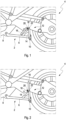
- the figures show an unclaimed example of a main stand for a tilting vehicle 4, provided overall with the reference number 2.
- the main stand 2 comprises a support element 6, which is rotatably fixed to a support structure 8 of the tilting vehicle 4.
- the support element 6 can be moved from a support position in which the support element 6 rests against a floor with a support section 10 and in which the tilting vehicle 4 is held by the support element 6 against movement, in particular tipping over, into a basic position ( Figures 1 and 2 ), in which the support element 6 is arranged at a contact-free distance from the floor.
- the main stand 2 comprises at least one actuating unit 12, which in the exemplary embodiment shown in the figures is fixed directly to the support element 6 and is fixed at least in sections so that it can move relative to the support element 6.
- the actuation unit 12 is from a rest position ( Figure 1 ), in which the extension of the actuation unit 12, viewed transversely to the longitudinal direction of the support element 6, is minimal, in an actuation position ( Figure 2 ) can be transferred in which the extension of the actuating unit 12, viewed transversely to the longitudinal direction of the support element 6, is maximum.
- the actuation unit 12 In the actuation position, the actuation unit 12 is operated by a user of the tilting vehicle 4 Transferring the support element 6 from the basic position into the support position can be actuated.
- the Figures 1 and 2 show an unclaimed example of the main stand 2, in which the actuation unit 12 comprises a stationary actuation element 14, which is fixed directly to the support element 6.
- the actuating element 14 extends obliquely away from the supporting element 6.
- a hinge means 18 is provided between the movable actuating element 16 and the stationary actuating element 14, through which the movable actuating element 16 moves from the rest position ( Figure 1 ) into the operating position ( Figure 2 ) can be transferred by rotation.
- the axis of rotation 20 of the hinge means 18 is spaced from a center of mass of the stationary actuating element 14, viewed transversely to the longitudinal direction of the stationary actuating element 14.
- the hinge means 18 includes a stop 22 which limits a movement of the movable actuating element 16 from the rest position to the actuating position when the actuating position is reached.
- the movable actuating element 16 is moved manually or by means of a foot by the user of the tilting vehicle 4 from the rest position ( Figure 1 ) into the operating position ( Figure 2 ) transferred. Due to the axis of rotation 20 being offset from the center of gravity of the movable actuating element 16, the movable actuating element 16 is held against the stop 22 in the actuating position due to gravity. In the actuation position, the actuation unit 12 can be actuated in order to transfer the support element 6 from the basic position into the support position.
- the actuation unit 12 serves as a lever.
- the movable actuating element 16 When the tilting vehicle 4 is transferred from the support position back to the rest position of the support element 6, the movable actuating element 16 is rotated about the axis of rotation 20 due to the rotational movement of the support element from the support position to the basic position due to the inertia.
- the movable actuating element 16 is automatically arranged in the rest position.
Landscapes
- Engineering & Computer Science (AREA)
- Mechanical Engineering (AREA)
- Mechanical Control Devices (AREA)
- Motorcycle And Bicycle Frame (AREA)
Description
- Die Erfindung betrifft einen Hauptständer für ein Neigefahrzeug mit den Merkmalen des Oberbegriffs des Anspruchs 1.
- Hauptständer für Neigefahrzeuge sind in unterschiedlichen Ausführungsformen aus dem Stand der Technik bekannt. Bei diesen stützt ein Stützelement mit einem Auflageabschnitt das Neigefahrzeug in einer Stützstellung des Stützelements das Neigefahrzeug gegen ein Bewegen, insbesondere Umkippen, ab. Um das Stützelement auf einfache Weise in die Stützstellung zu überführen, umfassen bekannte Hauptständer drehfest am Stützelement festgelegte Betätigungseinheiten, die sich schräg oder quer von dem Stützelement wegerstrecken.
- Hierbei hat es sich als nachteilig herausgestellt, dass die Betätigungseinheiten in einer Grundstellung des Stützelements, in der das Stützelement zum Boden beabstandet ist, sich derart in Richtung Sitzeinheit des Neigefahrzeugs erstrecken, dass ein Benutzer des Neigefahrzeugs mit einem Fuß- oder unterem Beinbereich beim Fahren mit dem Neigefahrzeug an die Betätigungseinheit anstößt.
- Gattungsgemäße Hauptständer sind bekannt aus
EP 1 854 710 A2 ,JP S60 121981 U CN 201 834 092 U . Das DokumentEP1854710A2 wird als der nächste Stand der Technik betrachtet. - Eine Aufgabe eines Ausführungsbeispiels der Erfindung ist, einen Hauptständer für ein Neigefahrzeug vorzuschlagen, durch den eine Beeinträchtigung des Nutzers des Neigefahrzeugs beim Betrieb des Neigefahrzeugs zumindest reduziert ist.
- Diese Aufgabe wird bei einem eingangs genannten Hauptständer dadurch gelöst, dass das bewegbare Betätigungselement und das ortsfeste Betätigungselement ineinander teleskopierbar ausgebildet sind, wobei die Betätigungseinheit zumindest durch eine Translationsbewegung in die Betätigungsposition überführbar ist.
- Dadurch, dass der Hauptständer eine Betätigungseinheit umfasst, die von einer Ruheposition in eine Betätigungsposition überführbar ist, ist die Betätigungseinheit in der Ruheposition bezüglich ihrer Erstreckung quer zur Längserstreckungsrichtung des Stützelements reduziert. Hierdurch kann bei Betrieb des Neigefahrzeugs gewährleistet werden, dass die Betätigungseinheit nicht mit dem Fuß- oder Beinbereich eines Nutzers des Neigefahrzeugs kollidiert.
- Dadurch, dass die Betätigungseinheit von der Ruheposition in die Betätigungsposition überführbar ist, ist zudem gewährleistet, dass beim gewünschten Betätigen des Hauptständers die Betätigungseinheit eine ausreichende Erstreckung umfasst, so dass der Hauptständer über die Betätigungseinheit betätigt werden kann, wobei das Stützelement von der Grundstellung in die Stützstellung überführt wird.
- Der Hauptständer kann dazu dienen, das Neigefahrzeug aufzubocken und wieder abzubocken. Im aufgebockten Zustand des Neigefahrzeugs ist mindestens eine Radeinheit des Neigefahrzeugs zum Boden beabstandet.
- Unter einem Neigefahrzeug werden Fahrräder, Motorräder oder motorradähnliche Kraftfahrzeuge, wie Motorroller, insbesondere zwei-, drei- oder vierrädrige Motorroller, Scooter, neigbare Trikes, Quads oder Dergleichen verstanden.
- Dadurch, dass die Betätigungseinheit bezüglich ihrer Erstreckung quer zur Längserstreckungsrichtung des Stützelements einstellbar ist, können zum Aufbocken günstige Hebelverhältnisse des Hauptständers zur Verfügung gestellt werden und gleichzeitig ein Kollidieren während der Fahrt mit dem Fuß- oder Beinbereich des Benutzers des Neigefahrzeugs verhindert werden.
- Durch das ortsfeste Betätigungselement und das bewegbare Betätigungselement ist gewährleistet, dass die Betätigungseinheit auf einfache Weise, beispielsweise durch einen Fuß des Benutzers des Neigefahrzeugs, von der Ruheposition in die Betätigungsposition überführbar ist. Darüber hinaus ist durch das Vorsehen eines ortsfesten Betätigungselements, das unmittelbar am Stützelement festgelegt ist, eine hohe Kraftübertragung, insbesondere ein Übertragen von hohen Drehmomenten, gewährleistet.
- Dadurch, dass das bewegbare Betätigungselement und das ortsfeste Betätigungselement ineinander teleskopierbar ausbildbar sind, kann die Betätigungseinheit auf einfache Weise und stufenlos in unterschiedliche Positionen mit unterschiedlichen Längserstreckungen ausgefahren werden.
- In einer nicht beanspruchten Ausführungsform des Hauptständers ist vorgesehen, dass die Betätigungseinheit mindestens ein relativ zum Stützelement bewegbares Betätigungselement umfasst, das von der Ruheposition in die Betätigungsposition und zurück durch Drehung um eine Drehachse überführbar ist.
- Solchenfalls kann die Drehachse beispielsweise unmittelbar am Übergang von dem Stützelement auf die Betätigungseinheit vorgesehen sein. Solchenfalls kann die Betätigungseinheit in der Ruheposition im Wesentlichen parallel zum Stützelement verlaufen und beim Überführen in die Betätigungsposition in Gänze bezüglich des Stützelements bewegt, insbesondere ausgeklappt, werden.
- Hierdurch ist eine besonders kompakte Anordnung der einzelnen Elemente des Hauptständers in der Grundstellung des Stützelements ermöglicht.
- Bei einer nicht beanspruchten Weiterbildung letztgenannter Ausführungsform ist vorgesehen dass die Betätigungseinheit ein Scharniermittel umfasst, das zwischen dem ortsfesten Betätigungselement und dem bewegbaren Betätigungselement angeordnet ist, das die Drehachse umfasst und durch das das bewegbare Betätigungselement um die Drehachse drehbar ist, wobei die Betätigungseinheit zumindest durch eine Rotationsbewegung um die Drehachse in die Betätigungsposition überführbar ist.
- Wenn die Betätigungseinheit das Scharniermittel umfasst, können das bewegbare Betätigungselement und das ortsfeste Betätigungselement einfach ausgebildet werden.
- Das bewegbare Betätigungselement und das ortsfeste Betätigungselement können einander zumindest in der Betätigungsposition bezüglich ihrer Längserstreckungsrichtung fortsetzen oder parallel oder schräg zueinander verlaufend angeordnet sein.
- Wenn die Betätigungseinheit das Scharniermittel umfasst, erweist es sich als vorteilhaft, wenn die Drehachse des Scharniermittels zu einem Massemittelpunkt des ortsfesten Betätigungselements quer zur Längserstreckungsrichtung des ortsfesten Betätigungselements betrachtet, beabstandet ist.
- Durch das Anordnen der Drehachse des Scharniermittels zum Massemittelpunkt des ortsfesten Betätigungselements, kann gewährleistet werden, dass das bewegbare Betätigungselement in der Betätigungsposition allein aufgrund seiner Schwerkraft in der Betätigungsposition gehalten werden.
- Darüber hinaus ist hierdurch gewährleistet, dass bei einem Überführen des Stützelements von der Stützstellung in die Grundstellung, das bewegbare Betätigungselement um die Drehachse des Scharniermittels von der Betätigungsposition in die Ruheposition zurückschnappt.
- Darüber hinaus ist bei einer nicht beanspruchten Weiterbildung der beiden letztgenannten Ausführungsformen vorgesehen, dass das Scharniermittel mindestens einen Anschlag umfasst, der eine Bewegung des bewegbaren Betätigungselements von der Ruheposition in die Betätigungsposition bei Erreichen der Betätigungsposition zumindest begrenzt.
- Hierdurch können das bewegbare Betätigungselement und das ortsfeste Betätigungselement in der Betätigungsposition flächenhaft aneinander anliegen.
- Zudem lässt sich hierdurch eine einfache und kostengünstige mechanische Umsetzung des Hauptständers gewährleisten.
- Um ein unbeabsichtigtes Überführen des bewegbaren Betätigungselements von der Ruheposition in die Betätigungsposition zumindest zu reduzieren, erweist es sich als vorteilhaft, wenn der Hauptständer zumindest ein Haltemittel umfasst, durch das das bewegbare Betätigungselement in der Ruheposition gegen ein Überführen in die Betätigungsposition festlegbar ist.
- Das Haltemittel lässt sich einfach und kostengünstig ausbilden, wenn das Haltemittel ein Federelement, wie Puffer, insbesondere Gummipuffer, und/oder ein Magnetelement umfasst.
- Hierdurch kann das bewegbare Betätigungselement mit einer ausreichenden Haltekraft in der Ruheposition festgelegt werden und für einen Benutzer des Neigefahrzeugs ohne große Kraftanstrengung von der Ruheposition in die Betätigungsposition überführt werden.
- Das Betätigen der Betätigungseinheit, insbesondere des bewegbaren Betätigungselements lässt sich weiter vereinfachen, wenn der Hauptständer mindestens ein als Umklappmittel ausgebildetes Spannmittel umfasst, durch das das bewegbare Betätigungselement in Abhängigkeit des zum ortsfesten Betätigungselements einbeschriebenen Winkels in die Ruheposition und in die Betätigungsposition spannbar ist.
- Solchenfalls kann das Umklappmittel beispielsweise eine Umklappfeder umfassen, durch die das bewegbare Betätigungselement bis zu einem bestimmten Winkel in Richtung auf die Ruheposition gespannt ist und bei Überschreiten des bestimmten Winkels in Richtung auf die Betätigungsposition spannbar ist. Solchenfalls kann das Umklappmittel auch ein Element des Haltemittels sein.
- Schließlich erweist es sich als vorteilhaft, wenn das Stützelement in der Stützstellung eine Radeinheit des Neigefahrzeugs zum Boden beabstandet.
- Weitere Merkmale, Einzelheiten und Vorteile der Erfindung ergeben sich aus den beigefügten Patentansprüchen, aus der zeichnerischen Darstellung und nachfolgenden Beschreibung einer bevorzugten Ausführungsform des Hauptständers.
- In der Zeichnung zeigt:
- Figur 1
- Eine perspektivische Seitenansicht auf ein nicht beanspruchtes Beispiel des Hauptständers mit einem Stützelement in einer Grundstellung und einer Betätigungseinheit in einer Ruheposition;
- Figur 2
- Eine perspektivische Seitenansicht auf ein nicht beanspruchtes Beispiel gemäß
Figur 1 mit dem Stützelement in der Grundstellung und der Betätigungseinheit in der Betätigungsposition. - Die Figuren zeigen ein nicht beanspruchtes Beispiel eines insgesamt mit dem Bezugszeichen 2 versehenen Hauptständers für ein Neigefahrzeug 4. Der Hauptständer 2 umfasst ein Stützelement 6, das an einer Tragstruktur 8 des Neigefahrzeugs 4 drehbar festgelegt ist. Das Stützelement 6 ist von einer Stützstellung, in der das Stützelement 6 mit einem Auflageabschnitt 10 an einem Boden anliegt und in der das Neigefahrzeug 4 durch das Stützelement 6 gegen ein Bewegen, insbesondere Umkippen, gehalten ist, in eine Grundstellung überführbar (
Figuren 1 und 2 ), in der das Stützelement 6 zum Boden berührungsfrei beabstandet angeordnet ist. - Darüber hinaus umfasst der Hauptständer 2 mindestens eine Betätigungseinheit 12, die bei dem in den Figuren gezeigten Ausführungsbeispiel unmittelbar am Stützelement 6 festgelegt und zumindest abschnittsweise relativ zum Stützelement 6 bewegbar festgelegt ist. Die Betätigungseinheit 12 ist von einer Ruheposition (
Figur 1 ), in der die Erstreckung der Betätigungseinheit 12 quer zur Längserstreckungsrichtung des Stützelements 6 betrachtet, minimal ist, in eine Betätigungsposition (Figur 2 ) überführbar, in der die Erstreckung der Betätigungseinheit 12 quer zur Längserstreckungsrichtung des Stützelements 6 betrachtet, maximal ist. In der Betätigungsposition ist die Betätigungseinheit 12 durch einen Benutzer des Neigefahrzeugs 4 zum Überführen des Stützelements 6 von der Grundstellung in die Stützstellung betätigbar. - Die
Figuren 1 und 2 zeigen ein nicht beanspruchtes Beispiel des Hauptständers 2, bei dem die Betätigungseinheit 12 ein ortsfestes Betätigungselement 14 umfasst, das unmittelbar am Stützelement 6 festgelegt ist. Das Betätigungselement 14 ist schräg vom Stützelement 6 wegerstreckt. Auf der dem Stützelement 6 abgewandten Ende des ortsfesten Betätigungselements 14 ist ein bewegbares Betätigungselement 16 am ortsfesten Betätigungselement 14 festgelegt. Hierbei ist zwischen dem bewegbaren Betätigungselement 16 und dem ortsfesten Betätigungselement 14 ein Scharniermittel 18 vorgesehen, durch das das bewegbare Betätigungselement 16 um eine Drehachse 20 von der Ruheposition (Figur 1 ) in die Betätigungsposition (Figur 2 ) mittels Drehung überführbar ist. Die Drehachse 20 des Scharniermittels 18 ist dabei zu einem Massemittelpunkt des ortsfesten Betätigungselement 14 quer zur Längserstreckungsrichtung des ortsfesten Betätigungselements 14 betrachtet, beabstandet. - Darüber hinaus umfasst das Scharniermittel 18 einen Anschlag 22, der eine Bewegung des bewegbaren Betätigungselements 16 von der Ruheposition in die Betätigungsposition bei Erreichen der Betätigungsposition begrenzt.
- Im Folgenden wird kurz die Wirkungsweise des Hauptständers 2 beschrieben:
Zum Überführen des Stützelement 6 von der Grundstellung in die Stützstellung, wird manuell oder mittels eines Fußes durch den Benutzer des Neigefahrzeugs 4 das bewegbare Betätigungselement 16 aus der Ruheposition (Figur 1 ) in die Betätigungsposition (Figur 2 ) überführt. Aufgrund der zum Schwerpunkt des bewegbaren Betätigungselements 16 versetzt verlaufenden Drehachse 20 wird das bewegbare Betätigungselement 16 an dem Anschlag 22 anliegend, in der Betätigungsposition aufgrund der Schwerkraft gehalten. In der Betätigungsposition ist die Betätigungseinheit 12 betätigbar, um das Stützelement 6 von der Grundstellung in die Stützstellung zu überführen. Die Betätigungseinheit 12 dient hierbei als Hebel. - Wenn das Neigefahrzeug 4 von der Stützstellung zurück in die Ruhestellung des Stützelements 6 überführt wird, wird hierbei, aufgrund der Drehbewegung des Stützelements von der Stützstellung in die Grundstellung aufgrund der Masseträgheit das bewegbare Betätigungselement 16 um die Drehachse 20 gedreht. Hierbei wird das bewegbare Betätigungselement 16 automatisch in der Ruheposition angeordnet.
- Die in der vorstehenden Beschreibung, in den Ansprüchen sowie in der Zeichnung offenbarten Merkmale der Erfindung, können sowohl einzeln, als auch in jeder beliebigen Kombination in der Verwirklichung der Erfindung in ihren verschiedenen Ausführungsformen wesentlich sein.
-
- 2
- Hauptständer
- 4
- Neigefahrzeug
- 6
- Stützelement
- 8
- Tragstruktur
- 10
- Auflageabschnitt
- 12
- Betätigungseinheit
- 14
- ortsfestes Betätigungselement
- 16
- bewegbares Betätigungselement
- 18
- Scharniermittel
- 20
- Drehachse
- 22
- Anschlag
Claims (2)
- Hauptständer (2) für ein Neigefahrzeug (4) mit mindestens einem Stützelement (6), das an einer Tragstruktur (8) des Neigefahrzeugs (4) drehbar festlegbar oder festgelegt ist und das von einer Stützstellung, in der das Stützelement (6) mit einem Auflageabschnitt (10) an einem Boden anlegbar ist oder anliegt und in der das Neigefahrzeug (4) durch das Stützelement (6) gegen ein Bewegen, insbesondere Umkippen, gehalten ist, in eine Grundstellung überführbar ist, in der das Stützelement (6) zum Boden berührungsfrei beabstandet angeordnet ist, und mit mindestens einer Betätigungseinheit (12), die mittelbar oder unmittelbar am Stützelement (6) und zumindest abschnittsweise relativ zum Stützelement (6) bewegbar festlegbar oder festgelegt ist und die von einer Ruheposition, in der die Erstreckung der Betätigungseinheit (12) quer zur Längserstreckungsrichtung des Stützelements (6) betrachtet minimal ist, in eine Betätigungsposition überführbar ist, in der die Erstreckung der Betätigungseinheit (12) quer zur Längserstreckungsrichtung des Stützelements (6) betrachtet maximal ist und durch einen Nutzer des Neigefahrzeugs (4) zum Überführen des Stützelements (6) von der Grundstellung in die Stützstellung betätigbar ist, wobei die Betätigungseinheit (12) mindestens ein relativ zum Stützelement (6) ortsfestes Betätigungselement (14) umfasst, das unmittelbar am Stützelement (12) festlegbar oder festgelegt ist, das quer oder schräg vom Stützelement (12) wegerstreckt ist und an dessen dem Stützelement (12) abgewandten Ende ein bewegbares Betätigungselement (16) festlegbar oder festgelegt ist, dadurch gekennzeichnet, dass das bewegbare Betätigungselement (16) und das ortsfeste Betätigungselement (14) ineinander teleskopierbar ausgebildet sind, wobei die Betätigungseinheit (12) zumindest durch eine Translationsbewegung in die Betätigungsposition überführbar ist.
- Hauptständer (2) nach Anspruch 1, dadurch gekennzeichnet, dass das Stützelement (6) in der Stützstellung eine Radeinheit des Neigefahrzeugs (4) zum Boden beabstandet.
Applications Claiming Priority (2)
| Application Number | Priority Date | Filing Date | Title |
|---|---|---|---|
| DE102020102690.0A DE102020102690A1 (de) | 2020-02-04 | 2020-02-04 | Hauptständer für ein Neigefahrzeug |
| PCT/EP2020/086187 WO2021155984A1 (de) | 2020-02-04 | 2020-12-15 | Hauptständer für ein neigefahrzeug |
Publications (2)
| Publication Number | Publication Date |
|---|---|
| EP4100302A1 EP4100302A1 (de) | 2022-12-14 |
| EP4100302B1 true EP4100302B1 (de) | 2024-02-14 |
Family
ID=74106001
Family Applications (1)
| Application Number | Title | Priority Date | Filing Date |
|---|---|---|---|
| EP20833766.7A Active EP4100302B1 (de) | 2020-02-04 | 2020-12-15 | Hauptständer für ein neigefahrzeug |
Country Status (3)
| Country | Link |
|---|---|
| EP (1) | EP4100302B1 (de) |
| DE (1) | DE102020102690A1 (de) |
| WO (1) | WO2021155984A1 (de) |
Family Cites Families (6)
| Publication number | Priority date | Publication date | Assignee | Title |
|---|---|---|---|---|
| GB134696A (en) | 1919-01-07 | 1919-11-13 | Arthur Stanley Bryer | Improvements in Stands for Motor Cycles, Cycles and the like. |
| JPS60121981U (ja) * | 1984-01-27 | 1985-08-17 | スズキ株式会社 | オ−トバイの主スタンド |
| DE19753745A1 (de) | 1997-12-04 | 1999-06-10 | Bayerische Motoren Werke Ag | Motorradstütze |
| TR200601460A2 (tr) | 2005-03-30 | 2006-10-26 | Tvs Motor Company Limited | Motorsiklet için ayaklık. |
| JP4815269B2 (ja) | 2006-05-12 | 2011-11-16 | 本田技研工業株式会社 | 二輪車のスタンド装置 |
| CN201834092U (zh) * | 2010-08-31 | 2011-05-18 | 王新军 | 电动车双脚撑助力杆 |
-
2020
- 2020-02-04 DE DE102020102690.0A patent/DE102020102690A1/de active Pending
- 2020-12-15 EP EP20833766.7A patent/EP4100302B1/de active Active
- 2020-12-15 WO PCT/EP2020/086187 patent/WO2021155984A1/de not_active Ceased
Also Published As
| Publication number | Publication date |
|---|---|
| DE102020102690A1 (de) | 2021-08-05 |
| WO2021155984A1 (de) | 2021-08-12 |
| EP4100302A1 (de) | 2022-12-14 |
Similar Documents
| Publication | Publication Date | Title |
|---|---|---|
| EP3554920B1 (de) | Lenkrad für eine kraftfahrzeuglenkung und lenksäule für ein kraftfahrzeug | |
| EP0752359B1 (de) | Längsverstellvorrichtung an einem Mantelrohrteleskop einer Lenkspindel in einem Kraftfahrzeug | |
| EP2107983B1 (de) | Lenksäule mit crasheinrichtung | |
| DE102014107816B4 (de) | Nutzfahrzeugsitz mit arretierbarem Querschlittenteil | |
| DE10301142B3 (de) | Lenksäule für ein Kraftfahrzeug | |
| EP0597406B1 (de) | Höhenverstellbare Hubstütze, vorzugsweise für Wohnmobile | |
| DE102005034952B3 (de) | Verstellbare Lenksäule für ein Kraftfahrzeug | |
| DE102017209745B4 (de) | Bedienanordnung für ein Steer-by-Wire Lenksystem eines Kraftfahrzeugs | |
| DE19853624A1 (de) | Kopfstützenanordnung für eine Sitzrückenlehne mit einem motorischen Kopfstützen-Verstellantrieb | |
| DE3941047C2 (de) | ||
| DE102015007784A1 (de) | Lenksäule mit elektro-mechanischer Fixiervorrichtung | |
| WO2007110054A2 (de) | Lenkeinrichtung und betriebsverfahren dafür | |
| DE4344681C2 (de) | Lenksäulenvorrichtung | |
| DE10294486B4 (de) | Aufprallaufnahme-Lenksäuleneinrichtung für Fahrzeuge | |
| DE102019200488A1 (de) | Lenksäule für ein Kraftfahrzeug | |
| WO2005028280A1 (de) | Lenksäulenanordnung mit einer in ihrer neigung und länge veränderbaren lenksäule | |
| DE102020102690A1 (de) | Hauptständer für ein Neigefahrzeug | |
| EP1713676A1 (de) | Lenkrad für ein kraftfahrzeug | |
| DE102019123678A1 (de) | Verstellvorrichtung für ein Verstellteil zur Nutzung in einem Fahrzeuginnenraum | |
| DE102015008649A1 (de) | Fahrzeugsitz und Fahrzeug | |
| EP1604881B1 (de) | Verstellbare Lenksäule und Betriebsverfahren für eine solche Lenksäule | |
| WO2005028279A1 (de) | Lenksäulenanordnung mit einer in ihrer neigung und länge veränderbaren lenksäule | |
| DE102006003430A1 (de) | Lenksäule mit feststehender Lenkradnabe und Verstellbarkeit des Lenkrades im Crashfall | |
| DE202026000248U1 (de) | Kippsicherung für Einachser | |
| DE102006034715B3 (de) | Klemmeinrichtung für eine verstellbare Lenksäule eines Kraftwagens |
Legal Events
| Date | Code | Title | Description |
|---|---|---|---|
| STAA | Information on the status of an ep patent application or granted ep patent |
Free format text: STATUS: UNKNOWN |
|
| STAA | Information on the status of an ep patent application or granted ep patent |
Free format text: STATUS: THE INTERNATIONAL PUBLICATION HAS BEEN MADE |
|
| PUAI | Public reference made under article 153(3) epc to a published international application that has entered the european phase |
Free format text: ORIGINAL CODE: 0009012 |
|
| STAA | Information on the status of an ep patent application or granted ep patent |
Free format text: STATUS: REQUEST FOR EXAMINATION WAS MADE |
|
| 17P | Request for examination filed |
Effective date: 20220712 |
|
| AK | Designated contracting states |
Kind code of ref document: A1 Designated state(s): AL AT BE BG CH CY CZ DE DK EE ES FI FR GB GR HR HU IE IS IT LI LT LU LV MC MK MT NL NO PL PT RO RS SE SI SK SM TR |
|
| DAV | Request for validation of the european patent (deleted) | ||
| DAX | Request for extension of the european patent (deleted) | ||
| P01 | Opt-out of the competence of the unified patent court (upc) registered |
Effective date: 20230502 |
|
| GRAP | Despatch of communication of intention to grant a patent |
Free format text: ORIGINAL CODE: EPIDOSNIGR1 |
|
| STAA | Information on the status of an ep patent application or granted ep patent |
Free format text: STATUS: GRANT OF PATENT IS INTENDED |
|
| INTG | Intention to grant announced |
Effective date: 20231030 |
|
| GRAS | Grant fee paid |
Free format text: ORIGINAL CODE: EPIDOSNIGR3 |
|
| GRAA | (expected) grant |
Free format text: ORIGINAL CODE: 0009210 |
|
| STAA | Information on the status of an ep patent application or granted ep patent |
Free format text: STATUS: THE PATENT HAS BEEN GRANTED |
|
| AK | Designated contracting states |
Kind code of ref document: B1 Designated state(s): AL AT BE BG CH CY CZ DE DK EE ES FI FR GB GR HR HU IE IS IT LI LT LU LV MC MK MT NL NO PL PT RO RS SE SI SK SM TR |
|
| REG | Reference to a national code |
Ref country code: GB Ref legal event code: FG4D Free format text: NOT ENGLISH |
|
| REG | Reference to a national code |
Ref country code: CH Ref legal event code: EP |
|
| REG | Reference to a national code |
Ref country code: DE Ref legal event code: R096 Ref document number: 502020007040 Country of ref document: DE |
|
| REG | Reference to a national code |
Ref country code: IE Ref legal event code: FG4D Free format text: LANGUAGE OF EP DOCUMENT: GERMAN |
|
| REG | Reference to a national code |
Ref country code: LT Ref legal event code: MG9D |
|
| REG | Reference to a national code |
Ref country code: NL Ref legal event code: MP Effective date: 20240214 |
|
| PG25 | Lapsed in a contracting state [announced via postgrant information from national office to epo] |
Ref country code: IS Free format text: LAPSE BECAUSE OF FAILURE TO SUBMIT A TRANSLATION OF THE DESCRIPTION OR TO PAY THE FEE WITHIN THE PRESCRIBED TIME-LIMIT Effective date: 20240614 |
|
| PG25 | Lapsed in a contracting state [announced via postgrant information from national office to epo] |
Ref country code: LT Free format text: LAPSE BECAUSE OF FAILURE TO SUBMIT A TRANSLATION OF THE DESCRIPTION OR TO PAY THE FEE WITHIN THE PRESCRIBED TIME-LIMIT Effective date: 20240214 |
|
| PG25 | Lapsed in a contracting state [announced via postgrant information from national office to epo] |
Ref country code: GR Free format text: LAPSE BECAUSE OF FAILURE TO SUBMIT A TRANSLATION OF THE DESCRIPTION OR TO PAY THE FEE WITHIN THE PRESCRIBED TIME-LIMIT Effective date: 20240515 |
|
| PG25 | Lapsed in a contracting state [announced via postgrant information from national office to epo] |
Ref country code: HR Free format text: LAPSE BECAUSE OF FAILURE TO SUBMIT A TRANSLATION OF THE DESCRIPTION OR TO PAY THE FEE WITHIN THE PRESCRIBED TIME-LIMIT Effective date: 20240214 Ref country code: RS Free format text: LAPSE BECAUSE OF FAILURE TO SUBMIT A TRANSLATION OF THE DESCRIPTION OR TO PAY THE FEE WITHIN THE PRESCRIBED TIME-LIMIT Effective date: 20240514 Ref country code: NL Free format text: LAPSE BECAUSE OF FAILURE TO SUBMIT A TRANSLATION OF THE DESCRIPTION OR TO PAY THE FEE WITHIN THE PRESCRIBED TIME-LIMIT Effective date: 20240214 |
|
| PG25 | Lapsed in a contracting state [announced via postgrant information from national office to epo] |
Ref country code: ES Free format text: LAPSE BECAUSE OF FAILURE TO SUBMIT A TRANSLATION OF THE DESCRIPTION OR TO PAY THE FEE WITHIN THE PRESCRIBED TIME-LIMIT Effective date: 20240214 |
|
| PG25 | Lapsed in a contracting state [announced via postgrant information from national office to epo] |
Ref country code: RS Free format text: LAPSE BECAUSE OF FAILURE TO SUBMIT A TRANSLATION OF THE DESCRIPTION OR TO PAY THE FEE WITHIN THE PRESCRIBED TIME-LIMIT Effective date: 20240514 Ref country code: NO Free format text: LAPSE BECAUSE OF FAILURE TO SUBMIT A TRANSLATION OF THE DESCRIPTION OR TO PAY THE FEE WITHIN THE PRESCRIBED TIME-LIMIT Effective date: 20240514 Ref country code: NL Free format text: LAPSE BECAUSE OF FAILURE TO SUBMIT A TRANSLATION OF THE DESCRIPTION OR TO PAY THE FEE WITHIN THE PRESCRIBED TIME-LIMIT Effective date: 20240214 Ref country code: LT Free format text: LAPSE BECAUSE OF FAILURE TO SUBMIT A TRANSLATION OF THE DESCRIPTION OR TO PAY THE FEE WITHIN THE PRESCRIBED TIME-LIMIT Effective date: 20240214 Ref country code: IS Free format text: LAPSE BECAUSE OF FAILURE TO SUBMIT A TRANSLATION OF THE DESCRIPTION OR TO PAY THE FEE WITHIN THE PRESCRIBED TIME-LIMIT Effective date: 20240614 Ref country code: HR Free format text: LAPSE BECAUSE OF FAILURE TO SUBMIT A TRANSLATION OF THE DESCRIPTION OR TO PAY THE FEE WITHIN THE PRESCRIBED TIME-LIMIT Effective date: 20240214 Ref country code: GR Free format text: LAPSE BECAUSE OF FAILURE TO SUBMIT A TRANSLATION OF THE DESCRIPTION OR TO PAY THE FEE WITHIN THE PRESCRIBED TIME-LIMIT Effective date: 20240515 Ref country code: FI Free format text: LAPSE BECAUSE OF FAILURE TO SUBMIT A TRANSLATION OF THE DESCRIPTION OR TO PAY THE FEE WITHIN THE PRESCRIBED TIME-LIMIT Effective date: 20240214 Ref country code: ES Free format text: LAPSE BECAUSE OF FAILURE TO SUBMIT A TRANSLATION OF THE DESCRIPTION OR TO PAY THE FEE WITHIN THE PRESCRIBED TIME-LIMIT Effective date: 20240214 Ref country code: BG Free format text: LAPSE BECAUSE OF FAILURE TO SUBMIT A TRANSLATION OF THE DESCRIPTION OR TO PAY THE FEE WITHIN THE PRESCRIBED TIME-LIMIT Effective date: 20240214 |
|
| PG25 | Lapsed in a contracting state [announced via postgrant information from national office to epo] |
Ref country code: PL Free format text: LAPSE BECAUSE OF FAILURE TO SUBMIT A TRANSLATION OF THE DESCRIPTION OR TO PAY THE FEE WITHIN THE PRESCRIBED TIME-LIMIT Effective date: 20240214 Ref country code: PT Free format text: LAPSE BECAUSE OF FAILURE TO SUBMIT A TRANSLATION OF THE DESCRIPTION OR TO PAY THE FEE WITHIN THE PRESCRIBED TIME-LIMIT Effective date: 20240614 |
|
| PG25 | Lapsed in a contracting state [announced via postgrant information from national office to epo] |
Ref country code: SE Free format text: LAPSE BECAUSE OF FAILURE TO SUBMIT A TRANSLATION OF THE DESCRIPTION OR TO PAY THE FEE WITHIN THE PRESCRIBED TIME-LIMIT Effective date: 20240214 Ref country code: PT Free format text: LAPSE BECAUSE OF FAILURE TO SUBMIT A TRANSLATION OF THE DESCRIPTION OR TO PAY THE FEE WITHIN THE PRESCRIBED TIME-LIMIT Effective date: 20240614 Ref country code: PL Free format text: LAPSE BECAUSE OF FAILURE TO SUBMIT A TRANSLATION OF THE DESCRIPTION OR TO PAY THE FEE WITHIN THE PRESCRIBED TIME-LIMIT Effective date: 20240214 Ref country code: LV Free format text: LAPSE BECAUSE OF FAILURE TO SUBMIT A TRANSLATION OF THE DESCRIPTION OR TO PAY THE FEE WITHIN THE PRESCRIBED TIME-LIMIT Effective date: 20240214 |
|
| PG25 | Lapsed in a contracting state [announced via postgrant information from national office to epo] |
Ref country code: DK Free format text: LAPSE BECAUSE OF FAILURE TO SUBMIT A TRANSLATION OF THE DESCRIPTION OR TO PAY THE FEE WITHIN THE PRESCRIBED TIME-LIMIT Effective date: 20240214 |
|
| PG25 | Lapsed in a contracting state [announced via postgrant information from national office to epo] |
Ref country code: SM Free format text: LAPSE BECAUSE OF FAILURE TO SUBMIT A TRANSLATION OF THE DESCRIPTION OR TO PAY THE FEE WITHIN THE PRESCRIBED TIME-LIMIT Effective date: 20240214 |
|
| PG25 | Lapsed in a contracting state [announced via postgrant information from national office to epo] |
Ref country code: EE Free format text: LAPSE BECAUSE OF FAILURE TO SUBMIT A TRANSLATION OF THE DESCRIPTION OR TO PAY THE FEE WITHIN THE PRESCRIBED TIME-LIMIT Effective date: 20240214 Ref country code: CZ Free format text: LAPSE BECAUSE OF FAILURE TO SUBMIT A TRANSLATION OF THE DESCRIPTION OR TO PAY THE FEE WITHIN THE PRESCRIBED TIME-LIMIT Effective date: 20240214 |
|
| PG25 | Lapsed in a contracting state [announced via postgrant information from national office to epo] |
Ref country code: SK Free format text: LAPSE BECAUSE OF FAILURE TO SUBMIT A TRANSLATION OF THE DESCRIPTION OR TO PAY THE FEE WITHIN THE PRESCRIBED TIME-LIMIT Effective date: 20240214 |
|
| PG25 | Lapsed in a contracting state [announced via postgrant information from national office to epo] |
Ref country code: SM Free format text: LAPSE BECAUSE OF FAILURE TO SUBMIT A TRANSLATION OF THE DESCRIPTION OR TO PAY THE FEE WITHIN THE PRESCRIBED TIME-LIMIT Effective date: 20240214 Ref country code: SK Free format text: LAPSE BECAUSE OF FAILURE TO SUBMIT A TRANSLATION OF THE DESCRIPTION OR TO PAY THE FEE WITHIN THE PRESCRIBED TIME-LIMIT Effective date: 20240214 Ref country code: RO Free format text: LAPSE BECAUSE OF FAILURE TO SUBMIT A TRANSLATION OF THE DESCRIPTION OR TO PAY THE FEE WITHIN THE PRESCRIBED TIME-LIMIT Effective date: 20240214 Ref country code: EE Free format text: LAPSE BECAUSE OF FAILURE TO SUBMIT A TRANSLATION OF THE DESCRIPTION OR TO PAY THE FEE WITHIN THE PRESCRIBED TIME-LIMIT Effective date: 20240214 Ref country code: DK Free format text: LAPSE BECAUSE OF FAILURE TO SUBMIT A TRANSLATION OF THE DESCRIPTION OR TO PAY THE FEE WITHIN THE PRESCRIBED TIME-LIMIT Effective date: 20240214 Ref country code: CZ Free format text: LAPSE BECAUSE OF FAILURE TO SUBMIT A TRANSLATION OF THE DESCRIPTION OR TO PAY THE FEE WITHIN THE PRESCRIBED TIME-LIMIT Effective date: 20240214 |
|
| REG | Reference to a national code |
Ref country code: DE Ref legal event code: R097 Ref document number: 502020007040 Country of ref document: DE |
|
| PLBE | No opposition filed within time limit |
Free format text: ORIGINAL CODE: 0009261 |
|
| STAA | Information on the status of an ep patent application or granted ep patent |
Free format text: STATUS: NO OPPOSITION FILED WITHIN TIME LIMIT |
|
| 26N | No opposition filed |
Effective date: 20241115 |
|
| PG25 | Lapsed in a contracting state [announced via postgrant information from national office to epo] |
Ref country code: SI Free format text: LAPSE BECAUSE OF FAILURE TO SUBMIT A TRANSLATION OF THE DESCRIPTION OR TO PAY THE FEE WITHIN THE PRESCRIBED TIME-LIMIT Effective date: 20240214 |
|
| PG25 | Lapsed in a contracting state [announced via postgrant information from national office to epo] |
Ref country code: MC Free format text: LAPSE BECAUSE OF FAILURE TO SUBMIT A TRANSLATION OF THE DESCRIPTION OR TO PAY THE FEE WITHIN THE PRESCRIBED TIME-LIMIT Effective date: 20240214 |
|
| REG | Reference to a national code |
Ref country code: CH Ref legal event code: PL |
|
| PG25 | Lapsed in a contracting state [announced via postgrant information from national office to epo] |
Ref country code: LU Free format text: LAPSE BECAUSE OF NON-PAYMENT OF DUE FEES Effective date: 20241215 |
|
| REG | Reference to a national code |
Ref country code: BE Ref legal event code: MM Effective date: 20241231 |
|
| PG25 | Lapsed in a contracting state [announced via postgrant information from national office to epo] |
Ref country code: BE Free format text: LAPSE BECAUSE OF NON-PAYMENT OF DUE FEES Effective date: 20241231 |
|
| PG25 | Lapsed in a contracting state [announced via postgrant information from national office to epo] |
Ref country code: CH Free format text: LAPSE BECAUSE OF NON-PAYMENT OF DUE FEES Effective date: 20241231 |
|
| PG25 | Lapsed in a contracting state [announced via postgrant information from national office to epo] |
Ref country code: IE Free format text: LAPSE BECAUSE OF NON-PAYMENT OF DUE FEES Effective date: 20241215 |
|
| PGFP | Annual fee paid to national office [announced via postgrant information from national office to epo] |
Ref country code: DE Payment date: 20251203 Year of fee payment: 6 |
|
| PGFP | Annual fee paid to national office [announced via postgrant information from national office to epo] |
Ref country code: GB Payment date: 20251218 Year of fee payment: 6 |
|
| PGFP | Annual fee paid to national office [announced via postgrant information from national office to epo] |
Ref country code: AT Payment date: 20260113 Year of fee payment: 5 |
|
| PGFP | Annual fee paid to national office [announced via postgrant information from national office to epo] |
Ref country code: FR Payment date: 20251218 Year of fee payment: 6 |
|
| PGFP | Annual fee paid to national office [announced via postgrant information from national office to epo] |
Ref country code: IT Payment date: 20251231 Year of fee payment: 6 |
|
| PG25 | Lapsed in a contracting state [announced via postgrant information from national office to epo] |
Ref country code: CY Free format text: LAPSE BECAUSE OF FAILURE TO SUBMIT A TRANSLATION OF THE DESCRIPTION OR TO PAY THE FEE WITHIN THE PRESCRIBED TIME-LIMIT Effective date: 20240214 |