EP4100281B1 - Headrest for motor vehicle seat - Google Patents
Headrest for motor vehicle seat Download PDFInfo
- Publication number
- EP4100281B1 EP4100281B1 EP21702509.7A EP21702509A EP4100281B1 EP 4100281 B1 EP4100281 B1 EP 4100281B1 EP 21702509 A EP21702509 A EP 21702509A EP 4100281 B1 EP4100281 B1 EP 4100281B1
- Authority
- EP
- European Patent Office
- Prior art keywords
- headrest
- tenon
- secondary body
- headrest according
- shells
- Prior art date
- Legal status (The legal status is an assumption and is not a legal conclusion. Google has not performed a legal analysis and makes no representation as to the accuracy of the status listed.)
- Active
Links
Images

Classifications
-
- B—PERFORMING OPERATIONS; TRANSPORTING
- B60—VEHICLES IN GENERAL
- B60N—SEATS SPECIALLY ADAPTED FOR VEHICLES; VEHICLE PASSENGER ACCOMMODATION NOT OTHERWISE PROVIDED FOR
- B60N2/00—Seats specially adapted for vehicles; Arrangement or mounting of seats in vehicles
- B60N2/80—Head-rests
- B60N2/806—Head-rests movable or adjustable
- B60N2/809—Head-rests movable or adjustable vertically slidable
-
- B—PERFORMING OPERATIONS; TRANSPORTING
- B60—VEHICLES IN GENERAL
- B60N—SEATS SPECIALLY ADAPTED FOR VEHICLES; VEHICLE PASSENGER ACCOMMODATION NOT OTHERWISE PROVIDED FOR
- B60N2/00—Seats specially adapted for vehicles; Arrangement or mounting of seats in vehicles
- B60N2/80—Head-rests
- B60N2/806—Head-rests movable or adjustable
- B60N2/865—Head-rests movable or adjustable providing a fore-and-aft movement with respect to the occupant's head
-
- B—PERFORMING OPERATIONS; TRANSPORTING
- B60—VEHICLES IN GENERAL
- B60N—SEATS SPECIALLY ADAPTED FOR VEHICLES; VEHICLE PASSENGER ACCOMMODATION NOT OTHERWISE PROVIDED FOR
- B60N2/00—Seats specially adapted for vehicles; Arrangement or mounting of seats in vehicles
- B60N2/80—Head-rests
- B60N2/894—Head-rests with rods solidly attached to the back-rest
-
- B—PERFORMING OPERATIONS; TRANSPORTING
- B60—VEHICLES IN GENERAL
- B60N—SEATS SPECIALLY ADAPTED FOR VEHICLES; VEHICLE PASSENGER ACCOMMODATION NOT OTHERWISE PROVIDED FOR
- B60N2205/00—General mechanical or structural details
- B60N2205/20—Measures for elimination or compensation of play or backlash
Definitions
- the invention relates to a headrest for a motor vehicle seat.
- the invention aims to overcome these drawbacks.
Landscapes
- Engineering & Computer Science (AREA)
- Aviation & Aerospace Engineering (AREA)
- Transportation (AREA)
- Mechanical Engineering (AREA)
- Seats For Vehicles (AREA)
Description
L'invention concerne un appui-tête de siège de véhicule automobile.The invention relates to a headrest for a motor vehicle seat.
Il est connu de réaliser un appui-tête de siège de véhicule automobile, ledit appui-tête comprenant :
- une armature de montage sur un dossier dudit siège,
- un corps principal monté en partie supérieure de ladite armature,
- un corps secondaire monté en coulissement longitudinal sur ledit corps principal, de sorte que ledit corps secondaire puisse adopter une pluralité de positions, ledit corps secondaire étant solidaire d'une paroi d'appui de la tête d'un passager.
- a mounting frame on a back of said seat,
- a main body mounted in the upper part of said frame,
- a secondary body mounted to slide longitudinally on said main body, so that said secondary body can adopt a plurality of positions, said secondary body being secured to a wall supporting the head of a passenger.
Cependant, les agencements connus comme celui de
- ne permettent pas de maîtriser au mieux le bon coulissement du corps secondaire par rapport au corps principal, ceci du fait de phénomènes d'arc-boutement et/ou de dispersions dimensionnelles nuisant audit coulissement et à la rigidité de l'ensemble,
- requièrent généralement un nombre important de moyens de rattrapage de jeux.
- do not allow for optimal control of the correct sliding of the secondary body in relation to the main body, due to arching phenomena and/or dimensional dispersions which are detrimental to said sliding and to the rigidity of the assembly,
- generally require a significant number of game recovery resources.
L'invention a pour but de pallier ces inconvénients.The invention aims to overcome these drawbacks.
A cet effet, l'invention propose un appui-tête de siège de véhicule automobile, ledit appui-tête comprenant :
- une armature de montage sur un dossier dudit siège,
- un corps principal monté en partie supérieure de ladite armature,
- un corps secondaire monté en coulissement longitudinal sur ledit corps principal, de sorte que ledit corps secondaire puisse adopter une pluralité de positions, ledit corps secondaire étant solidaire d'une paroi d'appui de la tête d'un passager,
- a mounting frame on a back of said seat,
- a main body mounted in the upper part of said frame,
- a secondary body mounted in longitudinal sliding on said main body, so that said secondary body can adopt a plurality of positions, said secondary body being integral with a wall supporting the head of a passenger,
Dans cette description, les termes de positionnement dans l'espace (haut, bas, supérieur, inférieur, longitudinal, transversal, latéral, avant, arrière, vertical, ...) sont pris en référence à l'appui-tête disposé dans le véhicule en situation d'utilisation.In this description, the terms of positioning in space (top, bottom, upper, lower, longitudinal, transverse, lateral, front, rear, vertical, etc.) are taken in reference to the headrest arranged in the vehicle in use.
Avec l'agencement proposé, on assure un guidage par des moyens disposés en zone périphérique de l'appui-tête, ce qui permet :
- de maîtriser au mieux le bon coulissement du corps secondaire par rapport au corps principal, avec suppression des phénomènes d'arc-boutement et/ou d'impact des dispersions dimensionnelles nuisant audit coulissement et à la rigidité de l'ensemble,
- de réduire le nombre de moyens de rattrapage de jeux, comme on le verra plus loin.
- to best control the correct sliding of the secondary body in relation to the main body, with elimination of the phenomena of buttressing and/or impact of dimensional dispersions which are detrimental to said sliding and to the rigidity of the assembly,
- to reduce the number of ways to catch up on games, as we will see later.
D'autres particularités et avantages de l'invention apparaîtront dans la description qui suit, faite en référence aux figures jointes, dans lesquelles :
- [
Fig.1 ] est une vue schématique en perspective partielle d'un appui-tête selon une réalisation, - [
Fig.2 ] est analogue à lafigure 1 en vue éclatée, - [
Fig.3 ] est une vue schématique selon une direction longitudinale du corps principal de la réalisation illustrée, - [
Fig.4 ] est une vue schématique selon une direction longitudinale du corps secondaire de la réalisation illustrée, - [
Fig.5 ] est une vue schématique selon une direction longitudinale du corps secondaire monté sur le corps principal, - [
Fig.6 ] est analogue à lafigure 1 , l'appui-tête étant pourvu en outre de deux coques.
- [
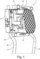
Fig. 1 ] is a partial schematic perspective view of a headrest according to one embodiment, - [
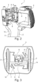
Fig.2 ] is analogous to theFigure 1 in exploded view, - [
Fig. 3 ] is a schematic view along a longitudinal direction of the main body of the illustrated embodiment, - [
Fig.4 ] is a schematic view along a longitudinal direction of the secondary body of the illustrated embodiment, - [
Fig.5 ] is a schematic view along a longitudinal direction of the secondary body mounted on the main body, - [
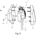
Fig.6 ] is analogous to theFigure 1 , the headrest being further provided with two shells.
En référence aux figures, on décrit un appui-tête 1 de siège de véhicule automobile, ledit appui-tête comprenant :
- une
armature 14 de montage sur un dossier dudit siège, - un corps principal 3 - notamment en matériau plastique moulé - monté en partie supérieure de ladite armature,
- un corps secondaire 4 - notamment en matériau plastique moulé - monté en coulissement longitudinal sur ledit corps principal, de sorte que ledit corps secondaire puisse adopter une pluralité de positions, ledit corps secondaire étant solidaire d'une paroi d'appui 5 de la tête d'un passager, ladite paroi étant notamment recouverte d'un coussin non représenté,
- a
frame 14 for mounting on a back of said seat, - a main body 3 - in particular made of molded plastic material - mounted in the upper part of said frame,
- a secondary body 4 - in particular made of molded plastic material - mounted to slide longitudinally on said main body, so that said secondary body can adopt a plurality of positions, said secondary body being integral with a
support wall 5 for the head of a passenger, said wall being in particular covered with a cushion not shown,
Selon la réalisation représentée, l'armature 14 comprend deux branches 2 tubulaires métalliques parallèles sensiblement verticales.According to the embodiment shown, the
Selon la réalisation représentée, les branches 2 de l'armature sont séparées l'une de l'autre.According to the embodiment shown, the
Selon une variante non représentée, les branches 2 se relient entre elles par une entretoise s'étendant entre leurs extrémités supérieures, l'armature étant notamment réalisée par pliage d'un tube métallique en U renversé, les branches du U correspondant aux branches 2 de ladite armature et sa partie intermédiaire formant ladite entretoise.According to a variant not shown, the
Selon la réalisation représentée, l'appui-tête 1 comprend deux tenons 6 se faisant face selon deux bords opposés - ici les bords supérieur et inférieur - du corps 4 sur lequel ils sont disposés, en l'occurrence le corps secondaire 4 selon la réalisation représentée.According to the embodiment shown, the
Selon la réalisation représentée, les tenons 6 se faisant face sont positionnés au milieu des bords concernés, ceci afin d'assurer un coulissement optimal du corps secondaire 4, y compris quand il est actionné par sa partie latérale.According to the embodiment shown, the
Une face latérale d'une mortaise 8 et/ou d'un tenon 6 est pourvue d'une patte 9 élastiquement rétractable, de manière à assurer un contact serrant avec le tenon 6 et/ou la mortaise 8 correspondant/e. Selon la réalisation représentée, la face latérale de la mortaise 8 est pourvue d'une patte 9 assurant un contact serrant avec le tenon 6 correspondant.A lateral face of a
Avec un tel agencement, on assure un rattrapage des jeux entre un tenon 6 et la mortaise 8 correspondante dans deux directions, à savoir les directions verticale et transversale.With such an arrangement, the clearances between a
Selon la réalisation représentée, la patte 9 est issue de moulage du corps 3 concerné - ici le corps principal 3 -, ladite patte étant solidaire dudit corps par une de ses extrémités 10, ladite patte étant mise en contrainte par un ressort métallique 7 pour assurer le contact serrant.According to the embodiment shown, the
Selon la réalisation représentée, le contact serrant est assuré par deux pattes 9 disposées respectivement en haut et en bas du corps 3 concerné - en l'occurrence le corps principal 3 selon la réalisation représentée -, lesdites pattes étant par ailleurs latéralement opposées, ce qui permet d'assurer un centrage à la fois vertical et transversal tout en minimisant le nombre desdites pattes.According to the embodiment shown, the clamping contact is ensured by two
Avec un tel agencement, on n'utilise que deux moyens de rattrapage de jeux formés par les deux pattes 9 associées aux ressorts 7.With such an arrangement, only two means of taking up play are used, formed by the two
De façon non représentée, l'appui-tête 1 peut comprendre en outre un dispositif de verrouillage du corps secondaire 4 selon une pluralité de positions, de sorte que la paroi d'appui 5 puisse présenter une pluralité de positions de réglage.In a manner not shown, the
Selon ne réalisation non représentée, le dispositif de verrouillage du corps secondaire 4 peut comprendre :
- une crémaillère issue dudit corps secondaire, ladite crémaillère s'étendant longitudinalement,
- un loquet monté mobile par rapport au corps principal 3 entre une position de verrouillage, où il s'insère un cran de ladite crémaillère, et une position de déverrouillage, où il se retire dudit cran afin de libérer le coulissement dudit corps secondaire.
- a rack originating from said secondary body, said rack extending longitudinally,
- a latch mounted to move relative to the
main body 3 between a locking position, where it is inserted into a notch of said rack, and an unlocking position, where it is withdrawn from said notch in order to release the sliding of said secondary body.
De façon non représentée, le corps principal 3 peut être monté en coulissement sur l'armature 14, et en particulier sur les branches 2, l'appui-tête 1 comprenant un dispositif de verrouillage en hauteur dudit corps, de manière à permettre son blocage dans une position de réglage.In a manner not shown, the
Selon une réalisation, le dispositif de verrouillage en hauteur peut comprendre :
- au moins une branche 2 crantée pourvue de crans de réglage s'étageant axialement, c'est à dire selon l'axe d'extension de ladite branche,
- au moins une saillie de verrouillage montée mobile par rapport
au corps principal 3 entre une position de verrouillage, où ladite saillie s'insère dans un desdits crans, et une position de déverrouillage, où ladite saillie se retire dudit cran afin de libérer le coulissement dudit corps.
- at least one notched
branch 2 provided with adjustment notches arranged axially, that is to say along the extension axis of said branch, - at least one locking projection mounted to move relative to the
main body 3 between a locking position, where said projection is inserted into one of said notches, and an unlocking position, where said projection is withdrawn from said notch in order to release the sliding of said body.
Selon diverses réalisations, le corps secondaire 4 peut être moulé d'une pièce avec la paroi d'appui 5 ou bien constituer une pièce séparée qui est montée sur ladite paroi.According to various embodiments, the
Selon la réalisation représentée, le corps secondaire 4 est solidaire de deux coques avant 11 et arrière 12 associées l'une à l'autre - ici au moyen de vis 13 - pour former un boitier logeant ledit corps, la paroi de ladite coque avant formant la paroi d'appui 5.According to the embodiment shown, the
Selon la réalisation représentée, le corps secondaire 4 est distinct des coques 11,12, ledit corps étant rendu solidaire desdites coques de par leur assemblage entre elles.According to the embodiment shown, the
Avec une telle réalisation, il est possible de réaliser le corps secondaire 4 à base de matériau plastique peu sujet à la déformation à la chaleur (par exemple du polyamide ou de l'acrylonitrile butadiène styrène), ce qui permet d'optimiser le guidage dudit corps à toutes les températures d'utilisation du véhicule, les coques 11,12 pouvant quant à elles être réalisées à base de matériau plastique (par exemple du polyéthylène haute densité) de moindre résistance aux fluctuations de température, et notamment moins coûteux.With such an embodiment, it is possible to produce the
Selon une réalisation non représentée, le corps secondaire 4 est moulé d'une pièce avec une des coques 11,12.According to an embodiment not shown, the
Dans ce cas, il convient de réaliser la coque 11,12 faisant un monobloc avec le corps secondaire 4 à base de matériau plastique peu sujet à la déformation à la chaleur (par exemple du polyamide ou de l'acrylonitrile butadiène styrène) si l'on souhaite optimiser le guidage dudit corps à toutes les températures d'utilisation du véhicule.In this case, it is appropriate to produce the
On peut bien sûr utiliser un matériau plastique de moindre qualité (par exemple du polyéthylène haute densité), mais on dispose alors d'un guidage moins performant.Of course, you can use a lower quality plastic material (for example, high-density polyethylene), but then you have less efficient guidance.
Claims (9)
- Headrest (1) for a motor vehicle seat, said headrest comprising:- a frame (14) for mounting on a backrest of said seat,- a main body (3) mounted on an upper part of said frame,- a secondary body (4) longitudinally slidably mounted on said main body, so that said secondary body can adopt a plurality of positions, said secondary body being connected with a support wall (5) of a passenger's head,said headrest being characterized in that said secondary body is mounted on said main body by at least one tenon (6) disposed at a periphery of one of said bodies, said tenon having, in longitudinal view, a shape inscribed in a trapezoid having a large inwardly-facing base and a small outwardly-facing base, said tenon sliding in a mortise (8) of complementary shape, opening out outwardly through said small base, provided in the other of said bodies, so as to form a dovetail-type fastening.
- Headrest according to claim 1, characterized in that it comprises two tenons (6) facing each other along two opposite edges of the body (4) on which they are arranged.
- A headrest according to one of claims 1 or 2, characterized in that one side face of a mortise (8) and/or tenon (6) is provided with an elastically retractable tab (9), so as to ensure clamping contact with the corresponding tenon (6) and/or mortise (8).
- Headrest according to claim 3, characterized in that the tab (9) is molded from the concerned body (3), said tab being connected with said body by one of its ends (10), said tab being stressed by a metal spring (7) to ensure the clamping contact.
- Headrest according to one of claims 3 or 4 when dependent on claim 2, characterized in that the clamping contact is ensured by two tabs (9) arranged respectively at the top and bottom of the concerned body (3), said tabs also being laterally opposed.
- Headrest according to any of the preceding claims, characterized in that it further comprises a device for locking the secondary body (4) in a plurality of positions, so that the support wall (5) can have a plurality of adjustment positions.
- Headrest according to any one of the preceding claims, characterized in that the secondary body (4) is connected with two front (11) and rear (12) shells associated with each other to form a housing accommodating said body, the wall of said front shell forming the support wall (5).
- Headrest according to claim 7, characterized in that the secondary body (4) is distinct from the shells (11, 12), said body being made connected with said shells by their assembly together.
- Headrest according to claim 7, characterized in that the secondary body (4) is molded in one piece with one of the shells (11, 12).
Applications Claiming Priority (2)
| Application Number | Priority Date | Filing Date | Title |
|---|---|---|---|
| FR2001104A FR3106792B1 (en) | 2020-02-04 | 2020-02-04 | Motor vehicle seat headrest |
| PCT/EP2021/052704 WO2021156386A1 (en) | 2020-02-04 | 2021-02-04 | Headrest for a motor vehicle seat |
Publications (2)
| Publication Number | Publication Date |
|---|---|
| EP4100281A1 EP4100281A1 (en) | 2022-12-14 |
| EP4100281B1 true EP4100281B1 (en) | 2025-04-02 |
Family
ID=70154740
Family Applications (1)
| Application Number | Title | Priority Date | Filing Date |
|---|---|---|---|
| EP21702509.7A Active EP4100281B1 (en) | 2020-02-04 | 2021-02-04 | Headrest for motor vehicle seat |
Country Status (4)
| Country | Link |
|---|---|
| EP (1) | EP4100281B1 (en) |
| ES (1) | ES3034278T3 (en) |
| FR (1) | FR3106792B1 (en) |
| WO (1) | WO2021156386A1 (en) |
Families Citing this family (4)
| Publication number | Priority date | Publication date | Assignee | Title |
|---|---|---|---|---|
| FR3137626B1 (en) * | 2022-07-07 | 2024-07-12 | Tesca France | Motor vehicle seat headrest |
| KR20240039391A (en) * | 2022-09-19 | 2024-03-26 | 현대자동차주식회사 | Headrest device for vehicle |
| FR3146439B1 (en) | 2023-03-10 | 2025-03-21 | Tesca France | Motor vehicle seat headrest |
| FR3158924B1 (en) | 2024-02-06 | 2026-02-13 | Tesca France | Motor vehicle seat headrest |
Family Cites Families (3)
| Publication number | Priority date | Publication date | Assignee | Title |
|---|---|---|---|---|
| DE3900495A1 (en) * | 1989-01-10 | 1990-07-26 | Bayerische Motoren Werke Ag | Head restraint for a motor-vehicle seat |
| DE20204949U1 (en) * | 2002-03-27 | 2003-06-12 | Grammer Ag, 92224 Amberg | Headrest of a vehicle seat comprises pivotable side sections provided with curved support elements with a series of depressions which interact with catches made of an entropy-elastic, compliant material |
| DE102018221626B3 (en) * | 2018-12-13 | 2019-10-24 | Magna Seating (Germany) Gmbh | Adjustable headrest assembly for a motor vehicle seat |
-
2020
- 2020-02-04 FR FR2001104A patent/FR3106792B1/en active Active
-
2021
- 2021-02-04 ES ES21702509T patent/ES3034278T3/en active Active
- 2021-02-04 WO PCT/EP2021/052704 patent/WO2021156386A1/en not_active Ceased
- 2021-02-04 EP EP21702509.7A patent/EP4100281B1/en active Active
Also Published As
| Publication number | Publication date |
|---|---|
| ES3034278T3 (en) | 2025-08-14 |
| EP4100281A1 (en) | 2022-12-14 |
| FR3106792A1 (en) | 2021-08-06 |
| FR3106792B1 (en) | 2023-09-08 |
| WO2021156386A1 (en) | 2021-08-12 |
Similar Documents
| Publication | Publication Date | Title |
|---|---|---|
| EP4100281B1 (en) | Headrest for motor vehicle seat | |
| FR2786141A1 (en) | Plastic sleeve for one branch of head rest support comprises elastically deformable internal ribs that move between two positions to center branch or make contact with central rib. | |
| FR2881089A1 (en) | HEAD-SUPPORT RECEIVING SHEATH | |
| FR3054176A1 (en) | HEADREST FOR THE SEAT OF A MOTOR VEHICLE | |
| FR3069499B1 (en) | HEADREST FOR THE SEAT OF A MOTOR VEHICLE | |
| EP1816027B1 (en) | Headrest assembly device with a curved rod in a rectilinear casing | |
| FR3137626A1 (en) | Motor vehicle seat headrest | |
| EP3932734A1 (en) | Headrest for a motor vehicle seat | |
| EP3708425A1 (en) | Headrest for a motor vehicle seat | |
| FR3146439A1 (en) | Motor vehicle seat headrest | |
| FR3068311B1 (en) | HEADREST FOR THE SEAT OF A MOTOR VEHICLE | |
| FR3054177B1 (en) | HEADREST FOR THE SEAT OF A MOTOR VEHICLE | |
| EP3386795B1 (en) | Arrangement for mounting an armrest on a vehicle door | |
| FR3132882A1 (en) | Motor vehicle seat headrest | |
| FR2868371A1 (en) | Motor vehicle rooftop bar mounting assembly, has fixing unit with passage opening and plate`s lower side equipped with housings for receiving sealing unit around opening and forming support surface on roof of motor vehicle | |
| FR3158924A1 (en) | Motor vehicle seat headrest | |
| FR3123026A1 (en) | Motor vehicle seat headrest | |
| WO2009112665A2 (en) | Device for slide-blocking a headrest rod including a slider reinforced by a part including a return means | |
| EP3529103A1 (en) | Headrest for a motor vehicle seat | |
| EP1857316A1 (en) | Front side of an automobile vehicle and associated automobile vehicle | |
| FR3121082A1 (en) | S ystem for mounting a motor vehicle seat headrest | |
| WO2024008908A1 (en) | Headrest for a motor vehicle seat | |
| FR3059925B1 (en) | METHOD FOR POSITIONING A CENTER CONSOLE USING A POSITIONING TOOL AND CORRESPONDING TOOL | |
| FR3158925A1 (en) | Motor vehicle seat headrest | |
| FR3021264A1 (en) | HEAD OFFICE |
Legal Events
| Date | Code | Title | Description |
|---|---|---|---|
| STAA | Information on the status of an ep patent application or granted ep patent |
Free format text: STATUS: UNKNOWN |
|
| STAA | Information on the status of an ep patent application or granted ep patent |
Free format text: STATUS: THE INTERNATIONAL PUBLICATION HAS BEEN MADE |
|
| PUAI | Public reference made under article 153(3) epc to a published international application that has entered the european phase |
Free format text: ORIGINAL CODE: 0009012 |
|
| STAA | Information on the status of an ep patent application or granted ep patent |
Free format text: STATUS: REQUEST FOR EXAMINATION WAS MADE |
|
| 17P | Request for examination filed |
Effective date: 20220902 |
|
| AK | Designated contracting states |
Kind code of ref document: A1 Designated state(s): AL AT BE BG CH CY CZ DE DK EE ES FI FR GB GR HR HU IE IS IT LI LT LU LV MC MK MT NL NO PL PT RO RS SE SI SK SM TR |
|
| DAV | Request for validation of the european patent (deleted) | ||
| DAX | Request for extension of the european patent (deleted) | ||
| GRAP | Despatch of communication of intention to grant a patent |
Free format text: ORIGINAL CODE: EPIDOSNIGR1 |
|
| STAA | Information on the status of an ep patent application or granted ep patent |
Free format text: STATUS: GRANT OF PATENT IS INTENDED |
|
| INTG | Intention to grant announced |
Effective date: 20241030 |
|
| GRAS | Grant fee paid |
Free format text: ORIGINAL CODE: EPIDOSNIGR3 |
|
| GRAA | (expected) grant |
Free format text: ORIGINAL CODE: 0009210 |
|
| STAA | Information on the status of an ep patent application or granted ep patent |
Free format text: STATUS: THE PATENT HAS BEEN GRANTED |
|
| AK | Designated contracting states |
Kind code of ref document: B1 Designated state(s): AL AT BE BG CH CY CZ DE DK EE ES FI FR GB GR HR HU IE IS IT LI LT LU LV MC MK MT NL NO PL PT RO RS SE SI SK SM TR |
|
| REG | Reference to a national code |
Ref country code: GB Ref legal event code: FG4D Free format text: NOT ENGLISH |
|
| REG | Reference to a national code |
Ref country code: CH Ref legal event code: EP |
|
| REG | Reference to a national code |
Ref country code: IE Ref legal event code: FG4D Free format text: LANGUAGE OF EP DOCUMENT: FRENCH |
|
| REG | Reference to a national code |
Ref country code: DE Ref legal event code: R096 Ref document number: 602021028480 Country of ref document: DE |
|
| REG | Reference to a national code |
Ref country code: NL Ref legal event code: MP Effective date: 20250402 |
|
| REG | Reference to a national code |
Ref country code: ES Ref legal event code: FG2A Ref document number: 3034278 Country of ref document: ES Kind code of ref document: T3 Effective date: 20250814 |
|
| PG25 | Lapsed in a contracting state [announced via postgrant information from national office to epo] |
Ref country code: NL Free format text: LAPSE BECAUSE OF FAILURE TO SUBMIT A TRANSLATION OF THE DESCRIPTION OR TO PAY THE FEE WITHIN THE PRESCRIBED TIME-LIMIT Effective date: 20250402 |
|
| REG | Reference to a national code |
Ref country code: AT Ref legal event code: MK05 Ref document number: 1780985 Country of ref document: AT Kind code of ref document: T Effective date: 20250402 |
|
| PG25 | Lapsed in a contracting state [announced via postgrant information from national office to epo] |
Ref country code: PT Free format text: LAPSE BECAUSE OF FAILURE TO SUBMIT A TRANSLATION OF THE DESCRIPTION OR TO PAY THE FEE WITHIN THE PRESCRIBED TIME-LIMIT Effective date: 20250804 Ref country code: FI Free format text: LAPSE BECAUSE OF FAILURE TO SUBMIT A TRANSLATION OF THE DESCRIPTION OR TO PAY THE FEE WITHIN THE PRESCRIBED TIME-LIMIT Effective date: 20250402 |
|
| REG | Reference to a national code |
Ref country code: LT Ref legal event code: MG9D |
|
| PG25 | Lapsed in a contracting state [announced via postgrant information from national office to epo] |
Ref country code: GR Free format text: LAPSE BECAUSE OF FAILURE TO SUBMIT A TRANSLATION OF THE DESCRIPTION OR TO PAY THE FEE WITHIN THE PRESCRIBED TIME-LIMIT Effective date: 20250703 Ref country code: NO Free format text: LAPSE BECAUSE OF FAILURE TO SUBMIT A TRANSLATION OF THE DESCRIPTION OR TO PAY THE FEE WITHIN THE PRESCRIBED TIME-LIMIT Effective date: 20250702 |
|
| PG25 | Lapsed in a contracting state [announced via postgrant information from national office to epo] |
Ref country code: PL Free format text: LAPSE BECAUSE OF FAILURE TO SUBMIT A TRANSLATION OF THE DESCRIPTION OR TO PAY THE FEE WITHIN THE PRESCRIBED TIME-LIMIT Effective date: 20250402 |
|
| PG25 | Lapsed in a contracting state [announced via postgrant information from national office to epo] |
Ref country code: BG Free format text: LAPSE BECAUSE OF FAILURE TO SUBMIT A TRANSLATION OF THE DESCRIPTION OR TO PAY THE FEE WITHIN THE PRESCRIBED TIME-LIMIT Effective date: 20250402 |
|
| PG25 | Lapsed in a contracting state [announced via postgrant information from national office to epo] |
Ref country code: HR Free format text: LAPSE BECAUSE OF FAILURE TO SUBMIT A TRANSLATION OF THE DESCRIPTION OR TO PAY THE FEE WITHIN THE PRESCRIBED TIME-LIMIT Effective date: 20250402 |
|
| PG25 | Lapsed in a contracting state [announced via postgrant information from national office to epo] |
Ref country code: AT Free format text: LAPSE BECAUSE OF FAILURE TO SUBMIT A TRANSLATION OF THE DESCRIPTION OR TO PAY THE FEE WITHIN THE PRESCRIBED TIME-LIMIT Effective date: 20250402 |
|
| PG25 | Lapsed in a contracting state [announced via postgrant information from national office to epo] |
Ref country code: RS Free format text: LAPSE BECAUSE OF FAILURE TO SUBMIT A TRANSLATION OF THE DESCRIPTION OR TO PAY THE FEE WITHIN THE PRESCRIBED TIME-LIMIT Effective date: 20250702 |
|
| PG25 | Lapsed in a contracting state [announced via postgrant information from national office to epo] |
Ref country code: IS Free format text: LAPSE BECAUSE OF FAILURE TO SUBMIT A TRANSLATION OF THE DESCRIPTION OR TO PAY THE FEE WITHIN THE PRESCRIBED TIME-LIMIT Effective date: 20250802 |
|
| PG25 | Lapsed in a contracting state [announced via postgrant information from national office to epo] |
Ref country code: LV Free format text: LAPSE BECAUSE OF FAILURE TO SUBMIT A TRANSLATION OF THE DESCRIPTION OR TO PAY THE FEE WITHIN THE PRESCRIBED TIME-LIMIT Effective date: 20250402 |
|
| PG25 | Lapsed in a contracting state [announced via postgrant information from national office to epo] |
Ref country code: SM Free format text: LAPSE BECAUSE OF FAILURE TO SUBMIT A TRANSLATION OF THE DESCRIPTION OR TO PAY THE FEE WITHIN THE PRESCRIBED TIME-LIMIT Effective date: 20250402 Ref country code: DK Free format text: LAPSE BECAUSE OF FAILURE TO SUBMIT A TRANSLATION OF THE DESCRIPTION OR TO PAY THE FEE WITHIN THE PRESCRIBED TIME-LIMIT Effective date: 20250402 |
|
| PG25 | Lapsed in a contracting state [announced via postgrant information from national office to epo] |
Ref country code: CZ Free format text: LAPSE BECAUSE OF FAILURE TO SUBMIT A TRANSLATION OF THE DESCRIPTION OR TO PAY THE FEE WITHIN THE PRESCRIBED TIME-LIMIT Effective date: 20250402 |
|
| PG25 | Lapsed in a contracting state [announced via postgrant information from national office to epo] |
Ref country code: EE Free format text: LAPSE BECAUSE OF FAILURE TO SUBMIT A TRANSLATION OF THE DESCRIPTION OR TO PAY THE FEE WITHIN THE PRESCRIBED TIME-LIMIT Effective date: 20250402 |
|
| PG25 | Lapsed in a contracting state [announced via postgrant information from national office to epo] |
Ref country code: SK Free format text: LAPSE BECAUSE OF FAILURE TO SUBMIT A TRANSLATION OF THE DESCRIPTION OR TO PAY THE FEE WITHIN THE PRESCRIBED TIME-LIMIT Effective date: 20250402 |
|
| PLBE | No opposition filed within time limit |
Free format text: ORIGINAL CODE: 0009261 |
|
| STAA | Information on the status of an ep patent application or granted ep patent |
Free format text: STATUS: NO OPPOSITION FILED WITHIN TIME LIMIT |
|
| REG | Reference to a national code |
Ref country code: CH Ref legal event code: L10 Free format text: ST27 STATUS EVENT CODE: U-0-0-L10-L00 (AS PROVIDED BY THE NATIONAL OFFICE) Effective date: 20260211 |