EP4099299B1 - Fahrzeugsteuerungsvorrichtung, fahrzeugsteuerungsverfahren und fahrzeugsteuerungssystem - Google Patents
Fahrzeugsteuerungsvorrichtung, fahrzeugsteuerungsverfahren und fahrzeugsteuerungssystem Download PDFInfo
- Publication number
- EP4099299B1 EP4099299B1 EP21747506.0A EP21747506A EP4099299B1 EP 4099299 B1 EP4099299 B1 EP 4099299B1 EP 21747506 A EP21747506 A EP 21747506A EP 4099299 B1 EP4099299 B1 EP 4099299B1
- Authority
- EP
- European Patent Office
- Prior art keywords
- vehicle
- driving
- driving area
- control unit
- area
- Prior art date
- Legal status (The legal status is an assumption and is not a legal conclusion. Google has not performed a legal analysis and makes no representation as to the accuracy of the status listed.)
- Active
Links
Images


Classifications
-
- B—PERFORMING OPERATIONS; TRANSPORTING
- B60—VEHICLES IN GENERAL
- B60W—CONJOINT CONTROL OF VEHICLE SUB-UNITS OF DIFFERENT TYPE OR DIFFERENT FUNCTION; CONTROL SYSTEMS SPECIALLY ADAPTED FOR HYBRID VEHICLES; ROAD VEHICLE DRIVE CONTROL SYSTEMS FOR PURPOSES NOT RELATED TO THE CONTROL OF A PARTICULAR SUB-UNIT
- B60W30/00—Purposes of road vehicle drive control systems not related to the control of a particular sub-unit, e.g. of systems using conjoint control of vehicle sub-units
- B60W30/14—Adaptive cruise control
- B60W30/143—Speed control
-
- B—PERFORMING OPERATIONS; TRANSPORTING
- B60—VEHICLES IN GENERAL
- B60W—CONJOINT CONTROL OF VEHICLE SUB-UNITS OF DIFFERENT TYPE OR DIFFERENT FUNCTION; CONTROL SYSTEMS SPECIALLY ADAPTED FOR HYBRID VEHICLES; ROAD VEHICLE DRIVE CONTROL SYSTEMS FOR PURPOSES NOT RELATED TO THE CONTROL OF A PARTICULAR SUB-UNIT
- B60W60/00—Drive control systems specially adapted for autonomous road vehicles
- B60W60/001—Planning or execution of driving tasks
- B60W60/0013—Planning or execution of driving tasks specially adapted for occupant comfort
-
- B—PERFORMING OPERATIONS; TRANSPORTING
- B60—VEHICLES IN GENERAL
- B60W—CONJOINT CONTROL OF VEHICLE SUB-UNITS OF DIFFERENT TYPE OR DIFFERENT FUNCTION; CONTROL SYSTEMS SPECIALLY ADAPTED FOR HYBRID VEHICLES; ROAD VEHICLE DRIVE CONTROL SYSTEMS FOR PURPOSES NOT RELATED TO THE CONTROL OF A PARTICULAR SUB-UNIT
- B60W50/00—Details of control systems for road vehicle drive control not related to the control of a particular sub-unit, e.g. process diagnostic or vehicle driver interfaces
- B60W50/0098—Details of control systems ensuring comfort, safety or stability not otherwise provided for
-
- B—PERFORMING OPERATIONS; TRANSPORTING
- B60—VEHICLES IN GENERAL
- B60W—CONJOINT CONTROL OF VEHICLE SUB-UNITS OF DIFFERENT TYPE OR DIFFERENT FUNCTION; CONTROL SYSTEMS SPECIALLY ADAPTED FOR HYBRID VEHICLES; ROAD VEHICLE DRIVE CONTROL SYSTEMS FOR PURPOSES NOT RELATED TO THE CONTROL OF A PARTICULAR SUB-UNIT
- B60W60/00—Drive control systems specially adapted for autonomous road vehicles
- B60W60/001—Planning or execution of driving tasks
- B60W60/0011—Planning or execution of driving tasks involving control alternatives for a single driving scenario, e.g. planning several paths to avoid obstacles
-
- G—PHYSICS
- G08—SIGNALLING
- G08G—TRAFFIC CONTROL SYSTEMS
- G08G1/00—Traffic control systems for road vehicles
- G08G1/16—Anti-collision systems
- G08G1/165—Anti-collision systems for passive traffic, e.g. including static obstacles, trees
-
- G—PHYSICS
- G08—SIGNALLING
- G08G—TRAFFIC CONTROL SYSTEMS
- G08G1/00—Traffic control systems for road vehicles
- G08G1/16—Anti-collision systems
- G08G1/166—Anti-collision systems for active traffic, e.g. moving vehicles, pedestrians, bikes
-
- B—PERFORMING OPERATIONS; TRANSPORTING
- B60—VEHICLES IN GENERAL
- B60W—CONJOINT CONTROL OF VEHICLE SUB-UNITS OF DIFFERENT TYPE OR DIFFERENT FUNCTION; CONTROL SYSTEMS SPECIALLY ADAPTED FOR HYBRID VEHICLES; ROAD VEHICLE DRIVE CONTROL SYSTEMS FOR PURPOSES NOT RELATED TO THE CONTROL OF A PARTICULAR SUB-UNIT
- B60W2520/00—Input parameters relating to overall vehicle dynamics
- B60W2520/12—Lateral speed
- B60W2520/125—Lateral acceleration
-
- B—PERFORMING OPERATIONS; TRANSPORTING
- B60—VEHICLES IN GENERAL
- B60W—CONJOINT CONTROL OF VEHICLE SUB-UNITS OF DIFFERENT TYPE OR DIFFERENT FUNCTION; CONTROL SYSTEMS SPECIALLY ADAPTED FOR HYBRID VEHICLES; ROAD VEHICLE DRIVE CONTROL SYSTEMS FOR PURPOSES NOT RELATED TO THE CONTROL OF A PARTICULAR SUB-UNIT
- B60W2552/00—Input parameters relating to infrastructure
- B60W2552/10—Number of lanes
-
- B—PERFORMING OPERATIONS; TRANSPORTING
- B60—VEHICLES IN GENERAL
- B60W—CONJOINT CONTROL OF VEHICLE SUB-UNITS OF DIFFERENT TYPE OR DIFFERENT FUNCTION; CONTROL SYSTEMS SPECIALLY ADAPTED FOR HYBRID VEHICLES; ROAD VEHICLE DRIVE CONTROL SYSTEMS FOR PURPOSES NOT RELATED TO THE CONTROL OF A PARTICULAR SUB-UNIT
- B60W2552/00—Input parameters relating to infrastructure
- B60W2552/15—Road slope, i.e. the inclination of a road segment in the longitudinal direction
-
- B—PERFORMING OPERATIONS; TRANSPORTING
- B60—VEHICLES IN GENERAL
- B60W—CONJOINT CONTROL OF VEHICLE SUB-UNITS OF DIFFERENT TYPE OR DIFFERENT FUNCTION; CONTROL SYSTEMS SPECIALLY ADAPTED FOR HYBRID VEHICLES; ROAD VEHICLE DRIVE CONTROL SYSTEMS FOR PURPOSES NOT RELATED TO THE CONTROL OF A PARTICULAR SUB-UNIT
- B60W2552/00—Input parameters relating to infrastructure
- B60W2552/20—Road profile, i.e. the change in elevation or curvature of a plurality of continuous road segments
-
- B—PERFORMING OPERATIONS; TRANSPORTING
- B60—VEHICLES IN GENERAL
- B60W—CONJOINT CONTROL OF VEHICLE SUB-UNITS OF DIFFERENT TYPE OR DIFFERENT FUNCTION; CONTROL SYSTEMS SPECIALLY ADAPTED FOR HYBRID VEHICLES; ROAD VEHICLE DRIVE CONTROL SYSTEMS FOR PURPOSES NOT RELATED TO THE CONTROL OF A PARTICULAR SUB-UNIT
- B60W2552/00—Input parameters relating to infrastructure
- B60W2552/35—Road bumpiness, e.g. potholes
-
- B—PERFORMING OPERATIONS; TRANSPORTING
- B60—VEHICLES IN GENERAL
- B60W—CONJOINT CONTROL OF VEHICLE SUB-UNITS OF DIFFERENT TYPE OR DIFFERENT FUNCTION; CONTROL SYSTEMS SPECIALLY ADAPTED FOR HYBRID VEHICLES; ROAD VEHICLE DRIVE CONTROL SYSTEMS FOR PURPOSES NOT RELATED TO THE CONTROL OF A PARTICULAR SUB-UNIT
- B60W2552/00—Input parameters relating to infrastructure
- B60W2552/40—Coefficient of friction
-
- B—PERFORMING OPERATIONS; TRANSPORTING
- B60—VEHICLES IN GENERAL
- B60W—CONJOINT CONTROL OF VEHICLE SUB-UNITS OF DIFFERENT TYPE OR DIFFERENT FUNCTION; CONTROL SYSTEMS SPECIALLY ADAPTED FOR HYBRID VEHICLES; ROAD VEHICLE DRIVE CONTROL SYSTEMS FOR PURPOSES NOT RELATED TO THE CONTROL OF A PARTICULAR SUB-UNIT
- B60W2552/00—Input parameters relating to infrastructure
- B60W2552/50—Barriers
-
- B—PERFORMING OPERATIONS; TRANSPORTING
- B60—VEHICLES IN GENERAL
- B60W—CONJOINT CONTROL OF VEHICLE SUB-UNITS OF DIFFERENT TYPE OR DIFFERENT FUNCTION; CONTROL SYSTEMS SPECIALLY ADAPTED FOR HYBRID VEHICLES; ROAD VEHICLE DRIVE CONTROL SYSTEMS FOR PURPOSES NOT RELATED TO THE CONTROL OF A PARTICULAR SUB-UNIT
- B60W2552/00—Input parameters relating to infrastructure
- B60W2552/53—Road markings, e.g. lane marker or crosswalk
-
- B—PERFORMING OPERATIONS; TRANSPORTING
- B60—VEHICLES IN GENERAL
- B60W—CONJOINT CONTROL OF VEHICLE SUB-UNITS OF DIFFERENT TYPE OR DIFFERENT FUNCTION; CONTROL SYSTEMS SPECIALLY ADAPTED FOR HYBRID VEHICLES; ROAD VEHICLE DRIVE CONTROL SYSTEMS FOR PURPOSES NOT RELATED TO THE CONTROL OF A PARTICULAR SUB-UNIT
- B60W2554/00—Input parameters relating to objects
- B60W2554/20—Static objects
-
- B—PERFORMING OPERATIONS; TRANSPORTING
- B60—VEHICLES IN GENERAL
- B60W—CONJOINT CONTROL OF VEHICLE SUB-UNITS OF DIFFERENT TYPE OR DIFFERENT FUNCTION; CONTROL SYSTEMS SPECIALLY ADAPTED FOR HYBRID VEHICLES; ROAD VEHICLE DRIVE CONTROL SYSTEMS FOR PURPOSES NOT RELATED TO THE CONTROL OF A PARTICULAR SUB-UNIT
- B60W2554/00—Input parameters relating to objects
- B60W2554/40—Dynamic objects, e.g. animals, windblown objects
-
- B—PERFORMING OPERATIONS; TRANSPORTING
- B60—VEHICLES IN GENERAL
- B60W—CONJOINT CONTROL OF VEHICLE SUB-UNITS OF DIFFERENT TYPE OR DIFFERENT FUNCTION; CONTROL SYSTEMS SPECIALLY ADAPTED FOR HYBRID VEHICLES; ROAD VEHICLE DRIVE CONTROL SYSTEMS FOR PURPOSES NOT RELATED TO THE CONTROL OF A PARTICULAR SUB-UNIT
- B60W2554/00—Input parameters relating to objects
- B60W2554/60—Traversable objects, e.g. speed bumps or curbs
-
- B—PERFORMING OPERATIONS; TRANSPORTING
- B60—VEHICLES IN GENERAL
- B60W—CONJOINT CONTROL OF VEHICLE SUB-UNITS OF DIFFERENT TYPE OR DIFFERENT FUNCTION; CONTROL SYSTEMS SPECIALLY ADAPTED FOR HYBRID VEHICLES; ROAD VEHICLE DRIVE CONTROL SYSTEMS FOR PURPOSES NOT RELATED TO THE CONTROL OF A PARTICULAR SUB-UNIT
- B60W2554/00—Input parameters relating to objects
- B60W2554/80—Spatial relation or speed relative to objects
-
- B—PERFORMING OPERATIONS; TRANSPORTING
- B60—VEHICLES IN GENERAL
- B60W—CONJOINT CONTROL OF VEHICLE SUB-UNITS OF DIFFERENT TYPE OR DIFFERENT FUNCTION; CONTROL SYSTEMS SPECIALLY ADAPTED FOR HYBRID VEHICLES; ROAD VEHICLE DRIVE CONTROL SYSTEMS FOR PURPOSES NOT RELATED TO THE CONTROL OF A PARTICULAR SUB-UNIT
- B60W2556/00—Input parameters relating to data
- B60W2556/40—High definition maps
-
- B—PERFORMING OPERATIONS; TRANSPORTING
- B60—VEHICLES IN GENERAL
- B60W—CONJOINT CONTROL OF VEHICLE SUB-UNITS OF DIFFERENT TYPE OR DIFFERENT FUNCTION; CONTROL SYSTEMS SPECIALLY ADAPTED FOR HYBRID VEHICLES; ROAD VEHICLE DRIVE CONTROL SYSTEMS FOR PURPOSES NOT RELATED TO THE CONTROL OF A PARTICULAR SUB-UNIT
- B60W2556/00—Input parameters relating to data
- B60W2556/45—External transmission of data to or from the vehicle
- B60W2556/50—External transmission of data to or from the vehicle of positioning data, e.g. GPS [Global Positioning System] data
-
- B—PERFORMING OPERATIONS; TRANSPORTING
- B60—VEHICLES IN GENERAL
- B60W—CONJOINT CONTROL OF VEHICLE SUB-UNITS OF DIFFERENT TYPE OR DIFFERENT FUNCTION; CONTROL SYSTEMS SPECIALLY ADAPTED FOR HYBRID VEHICLES; ROAD VEHICLE DRIVE CONTROL SYSTEMS FOR PURPOSES NOT RELATED TO THE CONTROL OF A PARTICULAR SUB-UNIT
- B60W2720/00—Output or target parameters relating to overall vehicle dynamics
- B60W2720/10—Longitudinal speed
- B60W2720/106—Longitudinal acceleration
-
- B—PERFORMING OPERATIONS; TRANSPORTING
- B60—VEHICLES IN GENERAL
- B60W—CONJOINT CONTROL OF VEHICLE SUB-UNITS OF DIFFERENT TYPE OR DIFFERENT FUNCTION; CONTROL SYSTEMS SPECIALLY ADAPTED FOR HYBRID VEHICLES; ROAD VEHICLE DRIVE CONTROL SYSTEMS FOR PURPOSES NOT RELATED TO THE CONTROL OF A PARTICULAR SUB-UNIT
- B60W2720/00—Output or target parameters relating to overall vehicle dynamics
- B60W2720/12—Lateral speed
- B60W2720/125—Lateral acceleration
Definitions
- the present invention relates to a vehicle control device, to a vehicle control method, and to a vehicle control system.
- the action plan includes a target vehicle speed after continuously increasing or decreasing beyond a unit time and a target time from a present time to a time when the target vehicle speed is achieved, and the microprocessor is configured to control the drive power source and the transmission so that the self-driving vehicle travels at a target vehicle acceleration set based on the target time and a vehicle speed change amount from the vehicle speed at the present time to the target vehicle speed.
- Prior art document US 2020 / 047 753 A1 refers to a vehicle control device, wherein a low-level short-terra trajectory generating unit generates a short-term trajectory by using the newest dynamic external environment recognition information while also using the same static external environment recognition information (lane shape information, or the like) as the static external environment recognition information used by a high-level medium-term trajectory generating unit. Performing such control prevents inconsistency between the external environment information (environment information) used by the low-level short-term trajectory generating unit and that used for a medium-term trajectory, which is a high-level trajectory, and makes stable trajectory output possible.
- Prior art document US 2019 / 176 836 A1 shows systems and methods directed to motion planning for an autonomous vehicle.
- a recognition and determination unit that recognizes and determines the situation and the like around a vehicle generates a target driving path based on its recognition and determination result, and a vehicle control unit controls the motion of the vehicle such that the vehicle runs on the target driving path.
- ride quality or comfort of the vehicle may be deteriorated, depending on the target driving path.
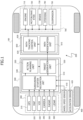
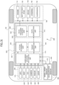
- Vehicle control system 200 includes an external information recognition unit 300, a vehicle motion detection unit 400, an automated driving control unit 500, a vehicle motion control unit 600, and an actuator unit 700.
- automated driving control unit 500 is an upper unit that gives a target command to vehicle motion control unit 600
- vehicle motion control unit 600 is a lower unit that acquires the target command from automated driving control unit 500.
- External information recognition unit 300 acquires external information about vehicle 100.
- Map database 320 is configured in a storage device mounted on vehicle 100.
- the map information in map database 320 includes information about road locations, road shapes, intersection locations, etc.
- Road-to-vehicle communication device 330 transmits information about vehicle 100 to roadside devices and receives road traffic information such as about curves and intersections from roadside devices.
- Camera 340 is a stereo camera, a monocular camera, a 360-degree camera, or the like. Camera 340 captures images around vehicle 100 and acquires information about the images around vehicle 100.
- Automated driving control unit 500 is an electronic control device including a microcomputer 540 as a main component that performs calculation based on input information and outputs calculation results.
- Microcomputer 540 includes, for example, a microprocessor unit (MPU), a read-only memory (ROM), a random access memory (RAM) (not illustrated).
- MPU microprocessor unit
- ROM read-only memory
- RAM random access memory
- Microcomputer 540 in automated driving control unit 500 calculates a target command based on the acquired information and outputs the calculated target command to vehicle motion control unit 600.
- Microcomputer 540 in automated driving control unit 500 includes a surrounding situation recognition unit 510, an action planning unit 520, and a target generation unit 530 as software functions.
- the situation around vehicle 100 recognized by surrounding situation recognition unit 510 includes, for example, information about a road curvature, cant of a road surface, a road surface gradient, a road surface friction coefficient ⁇ , locations of right and left lane markers (markings), locations of right and left road edges, moving objects, stationary objects, etc.
- Action planning unit 520 acquires a recognition result from surrounding situation recognition unit 510 and creates an action plan for vehicle 100.
- the action plan includes, for example, a selected driving lane and a selected traveling direction at an intersection or a branch point.
- the specifications relating to driving of the vehicle are physical quantities that minimize lateral acceleration or lateral jerk that occurs in vehicle 100.
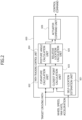
- Path modification unit 610 sets a target driving path and a target vehicle velocity, for example, as a driving path and a vehicle velocity that reduce lateral acceleration or lateral jerk as much as possible (that, in other words, minimize lateral acceleration or lateral jerk) within the driving area specified by automated driving control unit 500.
- Path tracking control unit 620 includes a self-location estimation unit 621, a curvature calculation unit 622, a closest point calculation unit 623, a posture angle calculation unit 624, a relative location calculation unit 625, and an actuator command unit 626.
- Closest point calculation unit 623 calculates the closest point, which is the point closest to the location of vehicle 100 on the target driving path.
- the steering command output by actuator command unit 626 includes, for example, a yaw rate command, a lateral location command, a yaw angle command, etc.
- automated driving control unit 500 can specify an area that does not include this object as the driving area.
- automated driving control unit 500 can set, for example, an area behind an object as a collision risk area on the alert for sudden appearance of an object from behind the object and can specify an area that does not include this collision risk area as the driving area.
- the road surface information is information about road surface friction coefficient ⁇ , cant of a road surface, a road surface slope, an undulating road surface, unevenness of the road surface, a speed bump, a pothole, etc.
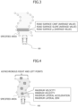
- the target command illustrated as an example in FIG. 3 specifies a driving area that is located away from the current location of vehicle 100 by a predetermined distance, by specifying a combination of location information about a right edge of the driving area and location information about a left edge of the driving area.
- road surface information such as the cant of the road surface, the road surface slope, and road surface friction coefficient ⁇ at the site represented by the corresponding location information are added.
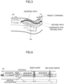
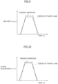
- the target command illustrated in FIG. 4 includes information about the maximum velocity, minimum velocity, maximum lateral acceleration, maximum lateral jerk, etc., per predetermined site.
- the maximum lateral acceleration of vehicle 100 is a value set based on, for example, ride quality of vehicle 100 or the maximum lateral acceleration allowable by automated driving
- the maximum lateral jerk of vehicle 100 is a value set based on, for example, ride quality of vehicle 100.
- FIG. 5 illustrates a driving area specified by automated driving control unit 500 and a target driving path set by vehicle motion control unit 600 on a curve.
- Vehicle motion control unit 600 drives vehicle 100 at a vehicle velocity and on a path that are based on specifications relating to driving of vehicle 100 within the specified driving area.
- vehicle motion control unit 600 can suitably select a velocity and a path that can ensure safety based on object information and that can achieve good ride quality with a reduced maximum lateral jerk, etc.
- vehicle motion control unit 600 sets a target driving path that bypasses the pothole, sets a target vehicle velocity such that vehicle 100 decelerates before the speed bump and the undulating road surface, and controls actuator unit 700 in accordance with the set target driving path and target vehicle velocity.
- vehicle motion control unit 600 may set a target vehicle velocity that accelerates vehicle 100 before the pothole.
- FIG. 7 illustrates an example of a driving path on a curve when vehicle motion control unit 600 drives vehicle 100 at a vehicle velocity and on a path that reduce the lateral acceleration or lateral jerk as much as possible within the driving area specified by automated driving control unit 500.
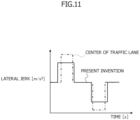
- FIGS. 8 to 11 each illustrate the difference in the curvature of a driving path, yaw rate, lateral acceleration, and lateral jerk, that is, the difference in the behavior of vehicle 100, between when vehicle 100 runs on a target driving path that traces the center of the traffic lane and when vehicle 100 runs on a target driving path that minimizes the lateral jerk.
- vehicle motion control unit 600 needs to set a target driving path such that the curvature of the driving path within the specified driving area becomes as small as possible. In other words, vehicle motion control unit 600 needs to set a target driving path such that vehicle 100 runs as linearly as possible.
- the curvature of the driving path of vehicle 100 (specifically, the maximum value of the curvature) becomes less than the curvature of the target driving path that traces the center of the traffic lane.
- the yaw rate that occurs when vehicle 100 is running on the curve also becomes small.
- the lateral acceleration that occurs when vehicle 100 is running on the curve also becomes small, and as illustrated in FIG. 11 , the lateral jerk that occurs when vehicle 100 is running on the curve also becomes small.
- FIG. 12 illustrates how automated driving control unit 500 specifies a driving area to vehicle motion control unit 600, in other words, how automated driving control unit 500 gives information specifying a driving area to vehicle motion control unit 600.
- the driving area specified by automated driving control unit 500 at time t2 partly overlaps the driving area previously specified at time t1.
- automated driving control unit 500 specifies the next driving area at time t3. Thereafter, automated driving control unit 500 periodically repeats specifying a driving area in the same way.
- Vehicle motion control unit 600 sequentially acquires information about a driving area from automated driving control unit 500, sets a target driving path that reduces the lateral acceleration or lateral jerk as much as possible, and outputs a control command for driving vehicle 100 on this target driving path to actuator unit 700.
- automated driving control unit 500 specifies the next driving area to vehicle motion control unit 600.
- vehicle motion control unit 600 acquires a driving area that partly overlaps the previously instructed driving area.
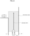
- FIG. 13 illustrates how automated driving control unit 500 creates a basic driving area.
- automated driving control unit 500 sets, as a driving area, an area between right and left lane markers RL and RR of the road in front of vehicle 100 or an area between the right and left edges of the road in front of vehicle 100.
- FIG. 14 illustrates how automated driving control unit 500 creates a driving area when a normal driving area set between the right and left lane markers RL and RR includes an object.
- a vehicle 110 is entering the traffic lane (in other words, the normal driving area) on which vehicle 100 is running from a sideway ahead of vehicle 100.
- automated driving control unit 500 specifies, as a driving area, an area obtained by removing an area including the vehicle 110 (that is, the object area) from the normal driving area to vehicle motion control unit 600.
- automated driving control unit 500 can change the size of the area to be removed from the normal driving area, depending on the moving direction and moving velocity of the object.
- automated driving control unit 500 can specify information about an area obtained by removing the object area from the normal driving area and can specify information about the normal driving area and information about the object area (in other words, information about the area to be removed from the normal driving area) to vehicle motion control unit 600.
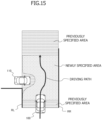
- FIGS. 15 and 16 each illustrate how automated driving control unit 500 creates and specifies a driving area when a predetermined situational change occurs in object information.
- automated driving control unit 500 quickly specifies a new driving area, that is, a driving area obtained by removing the object area including vehicle 110 from the traffic lane in which vehicle 100 is running, to vehicle motion control unit 600, without waiting for the reference driving area instruction timing.
- automated driving control unit 500 instructs vehicle motion control unit 600 to set a target driving path that avoids vehicle 110.
- automated driving control unit 500 can specify a driving area shorter than the normal driving area to vehicle motion control unit 600.
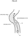
- FIG. 17 illustrates a case in which automated driving control unit 500 specifies a driving area including an area extending out to the right or left from a normal driving area.
- the example illustrated in FIG. 17 is a case in which vehicle 110 enters the traffic lane in which vehicle 100 is running and it is difficult for vehicle 100 to avoid vehicle 110 within the same traffic lane.
- automated driving control unit 500 specifies a driving area including a neighboring traffic lane (specifically, a passing traffic lane, an oncoming traffic lane, or the like) so that vehicle 100 can run beyond the current traffic lane to avoid vehicle 110.
- a neighboring traffic lane specifically, a passing traffic lane, an oncoming traffic lane, or the like
- automated driving control unit 500 determines whether certain conditions are met, e.g., whether no vehicle is running in a neighboring traffic lane. If these certain conditions are met, automated driving control unit 500 specifies a driving area extending out into the neighboring traffic lane from the current traffic lane to vehicle motion control unit 600.
- vehicle motion control unit 600 can drive vehicle 100 on the driving path that avoids the object within the current traffic lane.
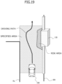
- the example illustrated in FIG. 18 is a situation in which there is a signboard 120 on the left side of a normal driving area (in other words, the current traffic lane) and there is a concern that, for example, a pedestrian may suddenly appear in the current traffic lane from a blind spot behind signboard 120.
- FIG. 19 illustrates a mode of a case in which automated driving control unit 500 specifies a driving area obtained by removing a collision risk area from a normal driving area.
- FIG. 18 illustrates a case in which an area near an object at a road edge is set as a collision risk area.
- automated driving control unit 500 specifies a driving area to vehicle motion control unit 600 and specifies, as object information, information about the location and the size of signboard 120 and information about the location and the size of stopped vehicle 140.
- Cant 150 of a road surface is a slope of a road surface in the lateral direction.
- automated driving control unit 500 specifies a driving area and also specifies information about the location and the size of signboard 120 as object information and information about the area of cant 150 of the road surface, the angle of the slope, and the direction of the slope as road surface information to vehicle motion control unit 600.
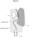
- FIG. 22 illustrates an example of a case in which the driving area includes signboard 120 as an object and a part of a road surface 160 having a low friction coefficient ⁇ (which will hereinafter be referred to as a low ⁇ road surface 160).
- vehicle motion control unit 600 sets a target driving path in view of the object information and the road surface information within the specified driving area.
- vehicle motion control unit 600 determines that vehicle 100 cannot run on the recommended path specified by automated driving control unit 500, vehicle motion control unit 600 calculates another target driving path that vehicle 100 can follow, in place of the recommended path.
- Vehicle motion control unit 600 can set a linear driving path within a driving area specified by automated driving control unit 500. In addition to that, vehicle motion control unit 600 can set driving paths as areas, each of which has a probability that vehicle 100 runs. This probability will hereinafter be referred to as driving probability. Vehicle motion control unit 600 can output a control command to actuator unit 700 such that vehicle 100 will pass through an area having a higher driving probability; in other words, vehicle 100 will pass through a location closer to a location at which an extreme probability is indicated.
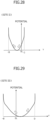
- FIGS. 26 to 29 each illustrate setting of a target driving path as an area having a probability that vehicle 100 runs.
- FIG. 26 illustrates a mode of a driving area specified by automated driving control unit 500, a path that vehicle 100 has actually run, and an area at which driving probability is high.
- Vehicle motion control unit 600 sets the driving probability, based on the driving area specified by automated driving control unit 500 in view of ride quality and comfort of vehicle 100, motion sickness, etc.
- vehicle motion control unit 600 sets the driving probability of vehicle 100 such that the extreme value is located a little to the right of reference line SL, that is, such that vehicle 100 runs on a path a little to the right of reference line SL at site II.
- distance D from reference line SL to the left edge of the driving area is longer than distance B from reference line SL to the left edge of the driving area.
- vehicle 100 run on a path a little to the left of reference line SL.
- FIGS. 1 and 30 Like elements between FIGS. 1 and 30 are denoted by like reference numerals, and detailed description thereof will be omitted.
- second microcomputer 820 has the functions of path modification unit 610 and path tracking control unit 620 illustrated in FIG. 1 , that is, has the control unit as a software function.
- Second logic 862 calculates a control command for driving vehicle 100 at a velocity and on a driving path that are based on specifications relating to driving of vehicle 100 within the driving area specified by first logic 861 and outputs the calculated control command to actuator unit 700.
- An integrated control unit 870 illustrated in FIG. 32 includes a first microcomputer 880 and a second microcomputer 890.
- the control unit can adjust the damping force or the vehicle height by controlling electronically controlled suspension 750.
- vehicle control system 200 may be configured such that a person in vehicle 100 can freely select the priority of the ride quality (specifically, the allowable maximum lateral acceleration or the allowable maximum lateral jerk) by operating a mode setting switch or the like.
- a driving path that passes through the collision risk area at a reduced target vehicle velocity may be set.
Landscapes
- Engineering & Computer Science (AREA)
- Automation & Control Theory (AREA)
- Transportation (AREA)
- Mechanical Engineering (AREA)
- Human Computer Interaction (AREA)
- Physics & Mathematics (AREA)
- General Physics & Mathematics (AREA)
- Traffic Control Systems (AREA)
- Control Of Driving Devices And Active Controlling Of Vehicle (AREA)
Claims (14)
- Fahrzeugsteuervorrichtung (600),- umfassend eine Steuereinheit (630), die konfiguriert ist, um eine Berechnung basierend auf Eingabeinformationen durchzuführen, und ein Berechnungsergebnis ausgibt,- wobei die Steuereinheit (630):- konfiguriert ist, um als einen ersten Fahrbereich einen Zielfahrbereich zu erfassen, der sich vor einem Fahrzeug (100) befindet und auf dem das Fahrzeug (100) fährt, wobei der Zielfahrbereich durch eine Erkennungs- und Bestimmungseinheit (540) spezifiziert ist, die eine Erkennung und Bestimmung einer Umgebungssituation des Fahrzeugs (100) durchführt,- konfiguriert ist, um zusammen mit Informationen über den ersten Fahrbereich Informationen über einen Mindestgeschwindigkeitswert des Fahrzeugs (100), einen Höchstgeschwindigkeitswert des Fahrzeugs (100), einen Höchstquerbeschleunigungswert und einen Höchstquerruckwert an einer vorbestimmten Stelle in dem ersten Fahrbereich zu erfassen, wobei die Informationen durch die Erkennungs- und Bestimmungseinheit (540) spezifiziert sind,- konfiguriert ist, um eine Zielgeschwindigkeit und einen Zielfahrweg des Fahrzeugs (100) zu berechnen, die eine Querbeschleunigung oder einen Querruck des Fahrzeugs (100) in dem ersten Fahrbereich so weit wie möglich reduzieren, um die Querbeschleunigung oder den Querruck des Fahrzeugs (100) zu minimieren,- konfiguriert ist, um an eine Aktuatoreinheit (700), die das Fahrzeug (100) antreibt, einen Steuerbefehl zum Antreiben des Fahrzeugs (100) mit der Zielgeschwindigkeit und auf dem Zielfahrweg auszugeben,- konfiguriert ist, um als einen zweiten Fahrbereich einen Zielfahrbereich zu erfassen, der sich vor dem Fahrzeug (100) befindet und auf dem das Fahrzeug (100) fährt, wobei der Zielfahrbereich den ersten Fahrbereich vor dem Fahrzeug (100) teilweise überlappt, während das Fahrzeug (100) in dem ersten Fahrbereich fährt, und wobei der Zielfahrbereich durch die Erkennungs- und Bestimmungseinheit (540) spezifiziert ist,- konfiguriert ist, um zusammen mit Informationen über den zweiten Fahrbereich Informationen über einen Mindestgeschwindigkeitswert des Fahrzeugs (100), einen Höchstgeschwindigkeitswert des Fahrzeugs (100), einen Höchstquerbeschleunigungswert und einen Höchstquerruckwert an einer vorbestimmten Stelle in dem zweiten Fahrbereich zu erfassen, wobei die Informationen durch die Erkennungs- und Bestimmungseinheit (540) spezifiziert sind,- konfiguriert ist, um eine Zielgeschwindigkeit und einen Zielfahrweg des Fahrzeugs (100) zu berechnen, die eine Querbeschleunigung oder einen Querruck des Fahrzeugs (100) in dem zweiten Fahrbereich so weit wie möglich reduzieren, um die Querbeschleunigung oder den Querruck des Fahrzeugs (100) zu minimieren, und- konfiguriert ist, um an die Aktuatoreinheit (700) einen Steuerbefehl zum Antreiben des Fahrzeugs (100) mit der Zielgeschwindigkeit und auf dem Zielfahrweg auszugeben.
- Fahrzeugsteuervorrichtung (600) nach Anspruch 1, wobei die Steuereinheit (630) konfiguriert ist, um den zweiten Fahrbereich zu erfassen, nachdem das Fahrzeug (100) für eine vorbestimmte Zeit in dem ersten Fahrbereich fährt.
- Fahrzeugsteuervorrichtung (600) nach Anspruch 2, wobei, während das Fahrzeug (100) in dem ersten Fahrbereich fährt, wenn die Steuereinheit (630) konfiguriert ist, um Informationen über eine vorbestimmte Situationsänderung in Straßenoberflächeninformationen oder Objektinformationen vor dem Fahrzeug (100) von der Erkennungs- und Bestimmungseinheit (540) zu erfassen, die Steuereinheit (630) den zweiten Fahrbereich erfasst, ob das Fahrzeug (100) für die vorbestimmte Zeit in dem ersten Fahrbereich gefahren ist oder nicht.
- Fahrzeugsteuervorrichtung (600) nach Anspruch 1, wobei der erste Fahrbereich und der zweite Fahrbereich jeweils ein Bereich zwischen rechten und linken Fahrspurmarkierungen einer Straße oder zwischen rechten und linken Rändern der Straße sind.
- Fahrzeugsteuervorrichtung (600) nach Anspruch 1, wobei der erste Fahrbereich und der zweite Fahrbereich jeweils ein Bereich sind, der keinen Bereich enthält, der einem Objekt vor dem Fahrzeug (100) entspricht.
- Fahrzeugsteuervorrichtung (600) nach Anspruch 1, wobei der erste Fahrbereich und der zweite Fahrbereich jeweils ein Bereich sind, der keinen Kollisionsrisikobereich vor dem Fahrzeug (100) enthält.
- Fahrzeugsteuervorrichtung (600) nach Anspruch 1, wobei die Steuereinheit (630) konfiguriert ist, um zusammen mit den Informationen über den ersten Fahrbereich und den zweiten Fahrbereich Informationen über Straßenoberflächeninformationen oder Objektinformationen vor dem Fahrzeug (100) zu erfassen, die durch eine Erkennungs- und Bestimmungseinheit (540) spezifiziert sind.
- Fahrzeugsteuervorrichtung (600) nach Anspruch 1, wobei die Steuereinheit (630) konfiguriert ist, um zusammen mit den Informationen über den ersten Fahrbereich und den zweiten Fahrbereich Informationen über einen empfohlenen Weg zu erfassen, auf dem das Fahrzeug (100) in dem entsprechenden des ersten Fahrbereichs und des zweiten Fahrbereichs fährt, die durch eine Erkennungs- und Bestimmungseinheit (540) spezifiziert sind.
- Fahrzeugsteuervorrichtung (600) nach Anspruch 1, wobei die Erkennungs- und Bestimmungseinheit (540) konfiguriert ist, um den ersten Fahrbereich und den zweiten Fahrbereich basierend auf Informationen von einer externen Informationserkennungseinheit (300) zu spezifizieren, die externe Informationen über das Fahrzeug (100) erfasst.
- Fahrzeugsteuerverfahren,das durch eine Steuereinheit (630) ausgeführt wird, die an einer Fahrzeugsteuervorrichtung (600) vorgesehen ist, die an einem Fahrzeug (100) montiert ist, unddas umfasst:- Erfassen, als einen ersten Fahrbereich, eines Zielfahrbereichs, der sich vor einem Fahrzeug (100) befindet und auf dem das Fahrzeug (100) fährt, wobei der Zielfahrbereich durch eine Erkennungs- und Bestimmungseinheit (540) spezifiziert ist, die eine Erkennung und Bestimmung einer Umgebungssituation des Fahrzeugs (100) durchführt;- Erfassen, zusammen mit Informationen über den ersten Fahrbereich, von Informationen über einen Mindestgeschwindigkeitswert des Fahrzeugs (100), einen Höchstgeschwindigkeitswert des Fahrzeugs (100), einen Höchstquerbeschleunigungswert und einen Höchstquerruckwert an einer vorbestimmten Stelle in dem ersten Fahrbereich, wobei die Informationen durch die Erkennungs- und Bestimmungseinheit (540) spezifiziert sind;- Berechnen einer Zielgeschwindigkeit und eines Zielfahrwegs des Fahrzeugs (100), die eine Querbeschleunigung oder einen Querruck des Fahrzeugs (100) in dem ersten Fahrbereich so weit wie möglich reduzieren, um die Querbeschleunigung oder den Querruck des Fahrzeugs (100) zu minimieren;- Ausgeben an eine Aktuatoreinheit (700), die das Fahrzeug (100) antreibt, eines Steuerbefehls zum Antreiben des Fahrzeugs (100) mit der Zielgeschwindigkeit und auf dem Zielfahrweg;- Erfassen, als einen zweiten Fahrbereich, eines Zielfahrbereichs, der sich vor einem Fahrzeug (100) befindet und auf dem ein Fahrzeug (100) fährt, wobei der Zielfahrbereich den ersten Fahrbereich vor dem Fahrzeug (100) teilweise überlappt, während das Fahrzeug (100) in dem ersten Fahrbereich fährt, und wobei der Zielfahrbereich durch die Erkennungs- und Bestimmungseinheit (540) spezifiziert ist;- Erfassen, zusammen mit Informationen über den zweiten Fahrbereich, von Informationen über einen Mindestgeschwindigkeitswert des Fahrzeugs (100), einen Höchstgeschwindigkeitswert des Fahrzeugs (100), einen Höchstquerbeschleunigungswert und einen Höchstquerruckwert an einer vorbestimmten Stelle in dem zweiten Fahrbereich, wobei die Informationen durch die Erkennungs- und Bestimmungseinheit (540) spezifiziert sind;- Berechnen einer Zielgeschwindigkeit und eines Zielfahrwegs des Fahrzeugs (100), die eine Querbeschleunigung oder einen Querruck des Fahrzeugs (100) in dem zweiten Fahrbereich so weit wie möglich reduzieren, um die Querbeschleunigung oder den Querruck des Fahrzeugs (100) zu minimieren; und- Ausgeben an die Aktuatoreinheit (700) eines Steuerbefehls zum Antreiben des Fahrzeugs (100) mit der Zielgeschwindigkeit und auf dem Zielfahrweg.
- Fahrzeugsteuersystem (200), umfassend:- eine Fahrzeugsteuervorrichtung (600) nach einem der Ansprüche 1 bis 9;- eine Erkennungs- und Bestimmungseinheit (540), die konfiguriert ist, um eine Erkennung und Bestimmung einer Umgebungssituation eines Fahrzeugs (100) durchzuführen; und- eine Aktuatoreinheit (700), die konfiguriert ist, um das Fahrzeug (100) anzutreiben.
- Fahrzeugsteuersystem (200) nach Anspruch 11, wobei:- die Erkennungs- und Bestimmungseinheit (540) in einer ersten Steuereinheit (500) bereitgestellt ist, und- die Steuereinheit (630) in einer zweiten Steuereinheit (600) bereitgestellt ist.
- Fahrzeugsteuersystem (200) nach Anspruch 14, wobei:- die Erkennungs- und Bestimmungseinheit (540) in einem ersten Mikrocomputer (810) bereitgestellt ist, der an einer Steuereinheit (800) montiert ist, und- die Steuereinheit (630) in einem zweiten Mikrocomputer (820) bereitgestellt ist, der an der Steuereinheit (800) montiert ist.
- Fahrzeugsteuersystem (200) nach Anspruch 11, wobei:- die Erkennungs- und Bestimmungseinheit (540) eine erste Logik (861) ist, die an einer (850) Steuereinheit montiert ist, und- die Steuereinheit (630) eine zweite Logik (862) ist, die an der Steuereinheit (850) montiert ist.
Applications Claiming Priority (2)
| Application Number | Priority Date | Filing Date | Title |
|---|---|---|---|
| JP2020013234 | 2020-01-30 | ||
| PCT/JP2021/002863 WO2021153622A1 (ja) | 2020-01-30 | 2021-01-27 | 車両制御装置、車両制御方法、及び車両制御システム |
Publications (3)
| Publication Number | Publication Date |
|---|---|
| EP4099299A1 EP4099299A1 (de) | 2022-12-07 |
| EP4099299A4 EP4099299A4 (de) | 2023-07-26 |
| EP4099299B1 true EP4099299B1 (de) | 2025-04-09 |
Family
ID=77079513
Family Applications (1)
| Application Number | Title | Priority Date | Filing Date |
|---|---|---|---|
| EP21747506.0A Active EP4099299B1 (de) | 2020-01-30 | 2021-01-27 | Fahrzeugsteuerungsvorrichtung, fahrzeugsteuerungsverfahren und fahrzeugsteuerungssystem |
Country Status (5)
| Country | Link |
|---|---|
| US (1) | US20230347888A1 (de) |
| EP (1) | EP4099299B1 (de) |
| JP (3) | JP7408695B2 (de) |
| CN (1) | CN115003577A (de) |
| WO (1) | WO2021153622A1 (de) |
Families Citing this family (8)
| Publication number | Priority date | Publication date | Assignee | Title |
|---|---|---|---|---|
| US20230347888A1 (en) | 2020-01-30 | 2023-11-02 | Hitachi Astemo, Ltd. | Vehicle Control Device, Vehicle Control Method, and Vehicle Control System |
| KR20220136679A (ko) * | 2021-04-01 | 2022-10-11 | 현대자동차주식회사 | 주행 제어 장치 및 방법 |
| CN115027481B (zh) * | 2022-05-20 | 2024-09-27 | 上汽通用五菱汽车股份有限公司 | 行驶路况检测方法、装置、电子设备及可读存储介质 |
| US12258039B2 (en) * | 2022-07-05 | 2025-03-25 | GM Global Technology Operations LLC | Method of determining a continuous driving path in the absence of a navigational route for autonomous vehicles |
| EP4357213B1 (de) * | 2022-10-17 | 2025-07-09 | Zenseact AB | Verfahren zur bestimmung, ob ein automatisches kollisionsvermeidungs-lenkmanöver ausgeführt werden soll oder nicht |
| JP2024108559A (ja) * | 2023-01-31 | 2024-08-13 | 京セラドキュメントソリューションズ株式会社 | 搬送装置 |
| FR3147219A1 (fr) * | 2023-03-28 | 2024-10-04 | Renault S.A.S | Procédé de modification autonome d’une trajectoire d’un véhicule automobile, dispositif de commande de trajectoire pour véhicule automobile et véhicule automobile comprenant un tel dispositif. |
| DE102024202202A1 (de) * | 2024-03-08 | 2025-09-11 | Zf Friedrichshafen Ag | Verfahren zur Fahrbahnzustandserkennung |
Family Cites Families (18)
| Publication number | Priority date | Publication date | Assignee | Title |
|---|---|---|---|---|
| DE19934670B4 (de) * | 1999-05-26 | 2004-07-08 | Robert Bosch Gmbh | Objektdetektionssystem |
| JP5502372B2 (ja) * | 2009-06-05 | 2014-05-28 | トヨタ自動車株式会社 | 車載電子システム |
| DE102010056389A1 (de) * | 2010-12-28 | 2012-06-28 | GM Global Technology Operations LLC | Verfahren und Überwachungsvorrichtung zum Überwachen eines Anfahrvorgangs eines Kraftfahrzeugs |
| EP3187389B1 (de) * | 2014-08-29 | 2019-11-06 | Nissan Motor Co., Ltd | Bewegungssteuerungsvorrichtung und bewegungssteuerungsverfahren |
| JP6280850B2 (ja) * | 2014-09-29 | 2018-02-14 | 日立建機株式会社 | 障害物回避システム |
| JP6367697B2 (ja) * | 2014-11-28 | 2018-08-01 | 株式会社デンソー | 物体検知装置 |
| JP6384296B2 (ja) | 2014-12-02 | 2018-09-05 | 日産自動車株式会社 | 車両の操舵制御装置及び車両の操舵制御方法 |
| US11142197B2 (en) * | 2016-10-18 | 2021-10-12 | Honda Motor Co., Ltd. | Vehicle control device |
| CN110023168B (zh) * | 2016-11-29 | 2022-03-08 | 本田技研工业株式会社 | 车辆控制系统、车辆控制方法及车辆控制程序 |
| DE102016015544A1 (de) * | 2016-12-27 | 2018-06-28 | Lucas Automotive Gmbh | Kraftfahrzeug-Steuergerät für eine elektrische Parkbremse |
| JP6814710B2 (ja) * | 2017-08-10 | 2021-01-20 | 日立オートモティブシステムズ株式会社 | 車両運動制御装置及びその方法、並びに、目標軌道生成装置及びその方法 |
| JP6580107B2 (ja) * | 2017-11-02 | 2019-09-25 | 本田技研工業株式会社 | 車両制御装置 |
| US11260875B2 (en) * | 2017-12-07 | 2022-03-01 | Uatc, Llc | Systems and methods for road surface dependent motion planning |
| US10823575B2 (en) * | 2018-06-27 | 2020-11-03 | Baidu Usa Llc | Reference line smoothing method using piecewise spiral curves with weighted geometry costs |
| CA3028601C (en) * | 2018-12-18 | 2021-10-26 | Beijing Didi Infinity Technology And Development Co., Ltd. | Systems and methods for determining driving path in autonomous driving |
| US11181922B2 (en) * | 2019-03-29 | 2021-11-23 | Zoox, Inc. | Extension of autonomous driving functionality to new regions |
| JP7215391B2 (ja) * | 2019-10-15 | 2023-01-31 | トヨタ自動車株式会社 | 自動運転車両の車両制御システム及び車両制御装置 |
| US20230347888A1 (en) | 2020-01-30 | 2023-11-02 | Hitachi Astemo, Ltd. | Vehicle Control Device, Vehicle Control Method, and Vehicle Control System |
-
2021
- 2021-01-27 US US17/796,468 patent/US20230347888A1/en active Pending
- 2021-01-27 EP EP21747506.0A patent/EP4099299B1/de active Active
- 2021-01-27 WO PCT/JP2021/002863 patent/WO2021153622A1/ja not_active Ceased
- 2021-01-27 JP JP2021574078A patent/JP7408695B2/ja active Active
- 2021-01-27 CN CN202180011491.8A patent/CN115003577A/zh active Pending
-
2023
- 2023-12-20 JP JP2023214403A patent/JP7659038B2/ja active Active
-
2025
- 2025-03-27 JP JP2025053461A patent/JP2025092586A/ja active Pending
Also Published As
| Publication number | Publication date |
|---|---|
| EP4099299A1 (de) | 2022-12-07 |
| JPWO2021153622A1 (de) | 2021-08-05 |
| EP4099299A4 (de) | 2023-07-26 |
| JP7659038B2 (ja) | 2025-04-08 |
| CN115003577A (zh) | 2022-09-02 |
| WO2021153622A1 (ja) | 2021-08-05 |
| US20230347888A1 (en) | 2023-11-02 |
| JP2024019638A (ja) | 2024-02-09 |
| JP2025092586A (ja) | 2025-06-19 |
| JP7408695B2 (ja) | 2024-01-05 |
Similar Documents
| Publication | Publication Date | Title |
|---|---|---|
| EP4099299B1 (de) | Fahrzeugsteuerungsvorrichtung, fahrzeugsteuerungsverfahren und fahrzeugsteuerungssystem | |
| US10890917B2 (en) | Vehicle controller | |
| US12233903B2 (en) | In-vehicle device and driving assist method | |
| JP6939428B2 (ja) | 車両制御装置 | |
| CN109789873B (zh) | 车辆控制装置 | |
| JP7205154B2 (ja) | 表示装置 | |
| KR102137933B1 (ko) | 차량 코너링 제어 방법 및 그 장치 | |
| CN109804420B (zh) | 车辆控制装置 | |
| CN112498365A (zh) | 基于置信度水平和距离、响应于障碍物的自动驾驶车辆的延迟决策 | |
| EP4458638A2 (de) | Verfahren und systeme zum autonomen fahren von fahrzeugen | |
| RU2724213C1 (ru) | Способ генерации целевой скорости и устройство генерации целевой скорости транспортного средства с содействием вождению | |
| JP6662316B2 (ja) | 車両制御システム | |
| US11577758B2 (en) | Autonomous vehicle park-and-go scenario design | |
| CN113552870A (zh) | 基于感知结果的动态速度限制调整系统及方法 | |
| CN113815640A (zh) | 用于具有不同速度限制的车道的车道变更系统 | |
| WO2018178052A1 (en) | Distance control for a vehicle with trailer | |
| WO2020249989A1 (ja) | 車両の走行制御方法及び走行制御装置 | |
| JP2023008265A (ja) | 車両走行制御装置および車両走行制御方法 | |
| JP7684776B2 (ja) | 車両制御装置、車両制御方法、及び車両制御システム | |
| EP4446186A1 (de) | Fahrzeugsteuerungsvorrichtung, fahrzeugsteuerungsverfahren und fahrzeugsteuerungssystem | |
| CN112829745A (zh) | 基于imu反馈的hd地图速度限制调整系统 | |
| US20240208504A1 (en) | Method for behavior planning of a vehicle | |
| US20250206317A1 (en) | Vehicle control device and vehicle control method | |
| US12134402B2 (en) | Planning under prediction with confidence region for an autonomous driving vehicle | |
| JP7749049B2 (ja) | 車両制御装置、車両制御方法、およびプログラム |
Legal Events
| Date | Code | Title | Description |
|---|---|---|---|
| STAA | Information on the status of an ep patent application or granted ep patent |
Free format text: STATUS: THE INTERNATIONAL PUBLICATION HAS BEEN MADE |
|
| PUAI | Public reference made under article 153(3) epc to a published international application that has entered the european phase |
Free format text: ORIGINAL CODE: 0009012 |
|
| STAA | Information on the status of an ep patent application or granted ep patent |
Free format text: STATUS: REQUEST FOR EXAMINATION WAS MADE |
|
| 17P | Request for examination filed |
Effective date: 20220721 |
|
| AK | Designated contracting states |
Kind code of ref document: A1 Designated state(s): AL AT BE BG CH CY CZ DE DK EE ES FI FR GB GR HR HU IE IS IT LI LT LU LV MC MK MT NL NO PL PT RO RS SE SI SK SM TR |
|
| DAV | Request for validation of the european patent (deleted) | ||
| DAX | Request for extension of the european patent (deleted) | ||
| A4 | Supplementary search report drawn up and despatched |
Effective date: 20230622 |
|
| RIC1 | Information provided on ipc code assigned before grant |
Ipc: B60W 30/10 20060101ALI20230616BHEP Ipc: B60W 30/09 20120101ALI20230616BHEP Ipc: G08G 1/16 20060101AFI20230616BHEP |
|
| STAA | Information on the status of an ep patent application or granted ep patent |
Free format text: STATUS: EXAMINATION IS IN PROGRESS |
|
| 17Q | First examination report despatched |
Effective date: 20240322 |
|
| GRAP | Despatch of communication of intention to grant a patent |
Free format text: ORIGINAL CODE: EPIDOSNIGR1 |
|
| STAA | Information on the status of an ep patent application or granted ep patent |
Free format text: STATUS: GRANT OF PATENT IS INTENDED |
|
| INTG | Intention to grant announced |
Effective date: 20241219 |
|
| GRAS | Grant fee paid |
Free format text: ORIGINAL CODE: EPIDOSNIGR3 |
|
| GRAA | (expected) grant |
Free format text: ORIGINAL CODE: 0009210 |
|
| STAA | Information on the status of an ep patent application or granted ep patent |
Free format text: STATUS: THE PATENT HAS BEEN GRANTED |
|
| AK | Designated contracting states |
Kind code of ref document: B1 Designated state(s): AL AT BE BG CH CY CZ DE DK EE ES FI FR GB GR HR HU IE IS IT LI LT LU LV MC MK MT NL NO PL PT RO RS SE SI SK SM TR |
|
| REG | Reference to a national code |
Ref country code: GB Ref legal event code: FG4D |
|
| REG | Reference to a national code |
Ref country code: CH Ref legal event code: EP |
|
| REG | Reference to a national code |
Ref country code: DE Ref legal event code: R096 Ref document number: 602021028934 Country of ref document: DE |
|
| REG | Reference to a national code |
Ref country code: IE Ref legal event code: FG4D |
|
| REG | Reference to a national code |
Ref country code: NL Ref legal event code: MP Effective date: 20250409 |
|
| PG25 | Lapsed in a contracting state [announced via postgrant information from national office to epo] |
Ref country code: NL Free format text: LAPSE BECAUSE OF FAILURE TO SUBMIT A TRANSLATION OF THE DESCRIPTION OR TO PAY THE FEE WITHIN THE PRESCRIBED TIME-LIMIT Effective date: 20250409 |
|
| REG | Reference to a national code |
Ref country code: AT Ref legal event code: MK05 Ref document number: 1784268 Country of ref document: AT Kind code of ref document: T Effective date: 20250409 |
|
| PG25 | Lapsed in a contracting state [announced via postgrant information from national office to epo] |
Ref country code: PT Free format text: LAPSE BECAUSE OF FAILURE TO SUBMIT A TRANSLATION OF THE DESCRIPTION OR TO PAY THE FEE WITHIN THE PRESCRIBED TIME-LIMIT Effective date: 20250811 Ref country code: ES Free format text: LAPSE BECAUSE OF FAILURE TO SUBMIT A TRANSLATION OF THE DESCRIPTION OR TO PAY THE FEE WITHIN THE PRESCRIBED TIME-LIMIT Effective date: 20250409 Ref country code: FI Free format text: LAPSE BECAUSE OF FAILURE TO SUBMIT A TRANSLATION OF THE DESCRIPTION OR TO PAY THE FEE WITHIN THE PRESCRIBED TIME-LIMIT Effective date: 20250409 |
|
| REG | Reference to a national code |
Ref country code: LT Ref legal event code: MG9D |
|
| PG25 | Lapsed in a contracting state [announced via postgrant information from national office to epo] |
Ref country code: NO Free format text: LAPSE BECAUSE OF FAILURE TO SUBMIT A TRANSLATION OF THE DESCRIPTION OR TO PAY THE FEE WITHIN THE PRESCRIBED TIME-LIMIT Effective date: 20250709 Ref country code: GR Free format text: LAPSE BECAUSE OF FAILURE TO SUBMIT A TRANSLATION OF THE DESCRIPTION OR TO PAY THE FEE WITHIN THE PRESCRIBED TIME-LIMIT Effective date: 20250710 |
|
| PG25 | Lapsed in a contracting state [announced via postgrant information from national office to epo] |
Ref country code: PL Free format text: LAPSE BECAUSE OF FAILURE TO SUBMIT A TRANSLATION OF THE DESCRIPTION OR TO PAY THE FEE WITHIN THE PRESCRIBED TIME-LIMIT Effective date: 20250409 |
|
| PG25 | Lapsed in a contracting state [announced via postgrant information from national office to epo] |
Ref country code: BG Free format text: LAPSE BECAUSE OF FAILURE TO SUBMIT A TRANSLATION OF THE DESCRIPTION OR TO PAY THE FEE WITHIN THE PRESCRIBED TIME-LIMIT Effective date: 20250409 |
|
| PG25 | Lapsed in a contracting state [announced via postgrant information from national office to epo] |
Ref country code: HR Free format text: LAPSE BECAUSE OF FAILURE TO SUBMIT A TRANSLATION OF THE DESCRIPTION OR TO PAY THE FEE WITHIN THE PRESCRIBED TIME-LIMIT Effective date: 20250409 |
|
| PG25 | Lapsed in a contracting state [announced via postgrant information from national office to epo] |
Ref country code: AT Free format text: LAPSE BECAUSE OF FAILURE TO SUBMIT A TRANSLATION OF THE DESCRIPTION OR TO PAY THE FEE WITHIN THE PRESCRIBED TIME-LIMIT Effective date: 20250409 |
|
| PG25 | Lapsed in a contracting state [announced via postgrant information from national office to epo] |
Ref country code: RS Free format text: LAPSE BECAUSE OF FAILURE TO SUBMIT A TRANSLATION OF THE DESCRIPTION OR TO PAY THE FEE WITHIN THE PRESCRIBED TIME-LIMIT Effective date: 20250709 |
|
| PG25 | Lapsed in a contracting state [announced via postgrant information from national office to epo] |
Ref country code: IS Free format text: LAPSE BECAUSE OF FAILURE TO SUBMIT A TRANSLATION OF THE DESCRIPTION OR TO PAY THE FEE WITHIN THE PRESCRIBED TIME-LIMIT Effective date: 20250809 |
|
| PG25 | Lapsed in a contracting state [announced via postgrant information from national office to epo] |
Ref country code: LV Free format text: LAPSE BECAUSE OF FAILURE TO SUBMIT A TRANSLATION OF THE DESCRIPTION OR TO PAY THE FEE WITHIN THE PRESCRIBED TIME-LIMIT Effective date: 20250409 |
|
| PG25 | Lapsed in a contracting state [announced via postgrant information from national office to epo] |
Ref country code: DK Free format text: LAPSE BECAUSE OF FAILURE TO SUBMIT A TRANSLATION OF THE DESCRIPTION OR TO PAY THE FEE WITHIN THE PRESCRIBED TIME-LIMIT Effective date: 20250409 Ref country code: SM Free format text: LAPSE BECAUSE OF FAILURE TO SUBMIT A TRANSLATION OF THE DESCRIPTION OR TO PAY THE FEE WITHIN THE PRESCRIBED TIME-LIMIT Effective date: 20250409 |
|
| PGFP | Annual fee paid to national office [announced via postgrant information from national office to epo] |
Ref country code: FR Payment date: 20251128 Year of fee payment: 6 |