EP4098983B1 - Zwei- oder dreidimensionales wattgestänge und die implementierung in einen seismischen sensor - Google Patents
Zwei- oder dreidimensionales wattgestänge und die implementierung in einen seismischen sensor Download PDFInfo
- Publication number
- EP4098983B1 EP4098983B1 EP22175640.6A EP22175640A EP4098983B1 EP 4098983 B1 EP4098983 B1 EP 4098983B1 EP 22175640 A EP22175640 A EP 22175640A EP 4098983 B1 EP4098983 B1 EP 4098983B1
- Authority
- EP
- European Patent Office
- Prior art keywords
- watt
- arm
- dimensional
- central
- linkage
- Prior art date
- Legal status (The legal status is an assumption and is not a legal conclusion. Google has not performed a legal analysis and makes no representation as to the accuracy of the status listed.)
- Active
Links
Images


Classifications
-
- G—PHYSICS
- G01—MEASURING; TESTING
- G01V—GEOPHYSICS; GRAVITATIONAL MEASUREMENTS; DETECTING MASSES OR OBJECTS; TAGS
- G01V1/00—Seismology; Seismic or acoustic prospecting or detecting
- G01V1/16—Receiving elements for seismic signals; Arrangements or adaptations of receiving elements
- G01V1/18—Receiving elements, e.g. seismometer, geophone or torque detectors, for localised single point measurements
-
- G—PHYSICS
- G01—MEASURING; TESTING
- G01H—MEASUREMENT OF MECHANICAL VIBRATIONS OR ULTRASONIC, SONIC OR INFRASONIC WAVES
- G01H1/00—Measuring characteristics of vibrations in solids by using direct conduction to the detector
-
- G—PHYSICS
- G01—MEASURING; TESTING
- G01P—MEASURING LINEAR OR ANGULAR SPEED, ACCELERATION, DECELERATION, OR SHOCK; INDICATING PRESENCE, ABSENCE, OR DIRECTION, OF MOVEMENT
- G01P15/00—Measuring acceleration; Measuring deceleration; Measuring shock, i.e. sudden change of acceleration
- G01P15/02—Measuring acceleration; Measuring deceleration; Measuring shock, i.e. sudden change of acceleration by making use of inertia forces using solid seismic masses
- G01P15/03—Measuring acceleration; Measuring deceleration; Measuring shock, i.e. sudden change of acceleration by making use of inertia forces using solid seismic masses by using non-electrical means
- G01P15/032—Measuring acceleration; Measuring deceleration; Measuring shock, i.e. sudden change of acceleration by making use of inertia forces using solid seismic masses by using non-electrical means by measuring the displacement of a movable inertial mass
Definitions
- the present invention is about a mechanism aimed at the implementation of multidimensional mechanical systems for scientific, civil and industrial applications, including, for example, seismic isolation systems, inertial platforms and broadband low frequency displacement, velocity and acceleration sensors.
- Watt's Linkage also known as “Parallel Linkage” or in Italian “parallelogramma di Watt”
- James Watt in 1774 [1]
- Folded Pendulum is a well-known mechanism, as well as its special configuration, internationally known as Folded Pendulum [2], widely used for the implementation of both seismic damping systems and broadband low frequency seismic sensors.
- two-dimensional and/or three-dimensional 'native' systems would be possible, among which we cite, as an example only, both systems for passive and/or active damping (seismic attenuators, inertial platforms, etc.) and, in complementary mode, systems for measuring displacements, velocities and accelerations (seismic sensors).
- the present research and development activity aimed at the design and implementation of attenuation systems and/or inertial platforms has as objective the decoupling of the activity carried out on it (experiments or measurements) from the local seismic noise (micro-earthquakes) and from anthropogenic noise, always present even in absence of earthquakes, allowing experiments, measurements and laboratory activities to be carried out on the earth's surface in better experimental conditions [12].
- the main purpose of these mechanisms is the decoupling or at least the reduction of the effects produced by external mechanical forcing on mechanical systems, regardless of the application for which they are designed.
- the latter category includes simple, double, triple pendulum isolators, in general multistage, such as the highly performing ones (super-attenuators), international state-of-the-art, used for low frequency seismic attenuation in interferometric gravitational wave detectors [16, 17, 18].
- the seismic isolators (attenuators) based, as mentioned above, on the classic Watt's linkage, made in the aforementioned particular configuration of the Folded Pendulum, can be framed within these architectures.
- the structure to be isolated is the inertial mass of the pendulum itself, which above the pendular resonance frequency tends to behave as a real inertial mass, "decoupled” from all the external forces acting on the point of application of the pendulum in the frequency band above its resonant frequency.
- the Folded Pendulum remains a one-dimensional mechanism. In fact, being based on the Watt's Linkage, it allows mechanical attenuation only in one direction, defined by the mechanism itself. At present, no extensions or developments have been made in the literature and/or planned or implementations allowing its direct application in several dimensions. This is highlighted by the fact that all the extensions hypothesized and/or implemented in several dimensions require several independent sensors positioned closed to each other, one for each degree of freedom [7, 8, 9].
- the present invention aims to provide a multidimensional Watt's Linkage, also in folded pendulum configuration, as well as seismic sensors, which, in whole or in part, solve the problems and overcome the drawbacks of the known art.
- the main object of the present invention is a mechanical multidimensional Watt's Linkage, a folded pendulum, as well as a seismic sensor, according to the attached claims.
- Two or more of the parts (elements, devices, systems) described according to the invention can be freely associated and considered as a kit of parts according to the invention.
- the Watt's Linkage is a mechanism invented by James Watt in 1784, also known in literature as Parallel Linkage, characterized by significant physical and geometric properties ( Fig. 1 ) [1, 2].
- the original mechanism consists of three rods: a central rod and two external rods of equal length, the latter connected by means of rotation joints both to the central rod and to external fixed points (base), a configuration that allows its classification also as kinematics [1, 2, 7, 8, 9].
- the motion of the geometric center of the central rod is a motion approximated by a straight line, therefore a one-dimensional motion, a fundamental characteristic of Watt's Linkage, which is used very effectively in a particular configuration, called Folded Pendulum, hypothesized for first time by Ferguson in 1962 [2].
- this configuration expresses the original idea of positioning the rods in such a way that the direction of the gravitational acceleration vector, g, is parallel to the longitudinal axes of the long rods and perpendicular to that of the central rod (configuration at rest), which can be interpreted physically as a combination of a simple pendulum and of an inverted pendulum (long rods), connected to the central rod (inertial mass) and to an external supporting structure (frame) ( Fig. 2 ).
- the Lagrangian model EFPM [9] (and its simplified version GFPM [7, 8]) allows us to write in a simple way the transfer functions that describe the dynamics of the motion of the central mass (inertial mass) with respect to the motion of the support and, consequently, the relative motion of the central mass with respect to the surface to which the Folded Pendulum is anchored in its applications.
- Fig. 3 shows the Folded Pendulum 300 positioned in the xz reference system, the latter oriented with the z axis parallel to the gravitational acceleration vector, g, and with the x axis perpendicular to it.
- the Folded Pendulum schematized (according to the EFPM model [9]) consists of two vertical rods AV of equal length, l p , both connected at one end to a support S by means of two rotation joints GR, thus implementing a simple pendulum of mass m p s and an inverse pendulum of mass m p i .
- the other two sides of the rods are connected to a horizontal rod, by means of two rotation joints ( C s and C i ) positioned at a relative distance l d . All four rotation joints are characterized by mutually parallel and perpendicular rotation axes to the xz plane, so that the whole motion of the Folded Pendulum is constrained in this xz plane.
- joints can be elastic joints (in compression and/or in traction of any shape and material, even pre-flexed), which are widely used in the monolithic configurations of Folded Pendulums and well modeled by the Tseytilin formula [21].
- the resonance frequency of the Folded Pendulum can be changed by introducing an external mass (calibration mass), m t , positioned at a distance, l t , from the center of rotation of the central rod, C s .
- Equation (7) is the classic expression of the resonance frequency of a mass-spring oscillator with an equivalent elastic constant equal to K eq and mass M eq .
- a unique feature of the Folded Pendulum is the possibility of implementing mechanical oscillators with a low resonance frequency by compensating for the equivalent elastic constant, K e eq , determined by the material and geometry of the joints themselves, with negative values of the global gravitational elastic constant, K g eq , which can be obtained by means of a suitable combination. of the physical and geometric parameters of the Folded Pendulum.
- this mechanical oscillator as a constituent element of a mechanical sensor, it is possible to analytically define its transfer function.
- the coordinate of the support as x f ( t )
- the transfer function of the mechanical oscillator that describes the displacement of this mass with respect to the displacement of the ground in the Laplace domain can be approximated to [7, 8, 9]
- H sensor s X c s ⁇ X g s
- X g s ⁇ 1 ⁇ A c s 2 s 2 + ⁇ o Q ⁇ o s + ⁇ o 2
- this mechanical oscillator as a constituent element of a mechanical attenuator, the transfer function is defined differently.
- Equation (15) highlights in a simple and direct way the application potential of the Folded Pendulum also as an attenuator and/or inertial platform (low residual motion due to support forcing) in the frequency band above the resonance frequency, which can also be calibrated at very low frequency values, given the peculiarities of the Folded Pendulum itself [5, 8, 9, 12].
- the original mechanism 100 consists of three rods (in solid black), all lying in a single plane: a central rod, B 1 C 1 , and two external rods of equal length, A 1 B 1 e C 1 D 1 , the latter connected by means of rotation joints (indicated with circles) both at the central rod and at external points, A 1 and D 1 , fixed in the reference system xyz .
- the rotation joints characterized by mutually parallel and perpendicular rotation axes to the plane of the mechanism A 1 B 1 C 1 D 1 (positioned, without any loss of generality, parallel to the xz plane in the xyz reference), constrain the motion of the whole mechanism in this plane.
- joints can be simple rotational joints but also elastic joints, for example elliptical and/or circular, a geometric configuration which is also very used in the monolithic implementations of Folded Pendulum and well modeled by the Tseytilin formula [21]. It is important to underline that the points A 1 e D 1 are fixed points in the reference system xz, so that they can be geometrically interpreted as ends of a virtual segment of fixed length and position, A 1 D 1 , base of the Watt's Linkage, however fully equivalent and replaceable, also for implementation purposes, from a real segment, A 1 D 1 , of identical length and fixed in the reference system xyz .
- This mechanical architecture has the important property that the geometric center of the central rod, E 1 , is constrained to trace a lemniscate (Watt's curve [1, 2]). The latter is with an excellent approximation a straight line (dashed in the figure) for small displacements (one-dimensional motion), an approximation the truer the greater the ratio between the length of the two external rods and the central rod.
- a second Watt's Linkage not necessarily identical, also consisting of three rods (indicated with lines with texture): a central rod, B 2 C 2 and two external rods of equal length, A 2 B 2 and C 2 D 2 , the latter connected by means of rotation joints (indicated with circles including a solid dot) to both the central rod and the base, A 2 D 2 .
- the rotation joints are characterized by mutually parallel and perpendicular rotation axes to the plane determined by A 2 B 2 C 2 D 2 , the plane in which the motion of the mechanism itself takes place.
- each single point belonging to the rods constituting the second Watt's Linkage including the point E 2 of the short rod B 2 C 2 , will be characterized by construction by two components, one along the direction of motion identified by E 1 in the plane A 1 B 1 C 1 D 1 and the other one along directions lying in the plane A 2 B 2 C 2 D 2 .
- the component of the motion of the point E 2 along the direction of motion identified by E 1 in the plane A 1 B 1 C 1 D 1 is represented by construction by the displacement, s E 1 , velocity, v E 1 , and acceleration, a E 1 , vectors.
- the component of motion of the different points constituting the second Watt's Linkage is represented by displacement, velocity and acceleration vectors lying by construction in the plane A 2 B 2 C 2 D 2 , which, in general, have variable orientations according to the different possible spatial configurations.
- the point E 2 move along a constant linear direction (one-dimensional motion).
- the point E 2 is constrained to move on a straight line (one-dimensional motion) in the plane identified by A 2 B 2 C 2 D 2 , with motion components represented by construction by the displacement, s E 2 , velocity, v E 2 , and acceleration, a E 2 , vectors.
- the point E 2 describes a curve in space which is here called “lemniscate in space", a combination of the lemniscates traced by geometric centers of the individual Watt's Linkage (see ref. [19] for the one-dimensional case). In such cases, it will be more or less difficult to obtain the effects of the invention depending on the degree of displacement in the non-linear regime and the possible compensation calibrations applied.
- the Watt linkages can be nested, as we will see in the case of the Folded Pendulum, since this configuration can be used to implement a two-dimensional or three-dimensional shock absorber in which what matters is not the parallelism of the arms with respect to the acceleration of gravity as in the Folded Pendulum, but the adaptation of the shape of the mechanism to the modification of the anchorage, as happens in the car shock absorber.
- the motion of the geometric center of the central rod of a classic one-dimensional Watt's Linkage is a very well approximated motion by a straight line (one-dimensional motion) for small displacements and for a high ratio between the length of the two external rods and the central rod, a condition imposed and verified in most of the projects.
- a three-dimensional reference system xyz , characterized by the xy plane parallel to the local horizontal and by the z axis parallel to the gravitational acceleration vector, g .
- these joints can be simple rotational joints but also elastic joints, for example elliptical and/or circular, in traction and/or compression [3, 4, 5], geometric configuration however widely used, in particular, in the monolithic implementations of Folded Pendulum [3, 4, 5, 7, 8, 9].
- the mechanical system is physically interpretable as a pendulum (rod A 1 B 1 ) , an inverse pendulum (rod C 1 D 1 ) connected on one side to the base A 1 D 1 and on the other to the central rod (inertial mass) B 1 C 1 .
- the mechanism shown in the figure is in fact a classic one-dimensional Ferguson Folded Pendulum, the basic element of all the implementations carried out so far of inertial platforms, one-dimensional attenuators and of one-dimensional seismic sensors using it as mechanical oscillator.
- the geometric center, E 1 , of the rod B 1 C 1 is constrained to move only horizontally in the A 1 B 1 C 1 D 1 plane and, therefore, parallel to the x axis.
- the Watt's Linkage A 2 B 2 C 2 D 2 is configured in such a way that the rods A 2 D 2 and C 2 D 2 are positioned parallel to the z axis and, therefore, in fact, parallel to the gravitational acceleration vector, g , with the rod B 2 C 2 , this time parallel to the y axis. Also this second mechanism, as it has been configured, is in fact a classic one-dimensional Folded Pendulum oriented perpendicular to the first.
- the geometric center, E 2 , of the rod B 2 C 2 is constrained by construction to move only horizontally in the plane A 2 B 2 C 2 D 2 , along a direction parallel to the y axis.
- point E 2 describes a "lemniscate in space", a combination of the lemniscate traced by the geometric centers of the individual Watt's Linkage (see ref. [19] for the one-dimensional case).
- This new mechanism is the first example of a two-dimensional Folded Pendulum, and therefore of a native two-dimensional oscillator with independent resonance frequencies related to each direction.
- the two components of the motion relative to the two directions, and therefore displacements, velocities and accelerations remain totally independent, each determined only by the forcing relative to the respective component, characterized by resonance frequencies dependent only on the physical and geometric parameters of the corresponding Folded Pendulum, a property that allows the complete decoupling of the directions of origin of the external forcing.
- an appropriate choice of the physical and geometric parameters of the two Folded Pendulums and/or the use of appropriate calibration masses coupled to a suitable choice of the elasticity coefficients of the elastic joints, whether in traction or compression, as summarized in the previous section and extensively described for a one-dimensional Folded Pendulum in [3, 4, 5, 7, 8, 9], can allow the implementation of a two-dimensional mechanical oscillator characterized by a single resonance frequency, and, therefore, a homogeneous dynamic behavior in both directions, always allowing the perfect decoupling of the signals coming from the two orthogonal directions.
- Equation (7) it is necessary to use the general formula given by Equation (7), written twice for x and y, and solved as a system by placing ⁇ 0x and ⁇ 0y identical. Equation (7) must be written for each degree of freedom, since each pendulum allows the measurement of motion only in a specific direction. Therefore, in practice, in order to have the same resonance frequency in both directions, the parameters of the pendulums must be appropriately chosen, including the masses and lengths of the arms, the calibration masses, the ellipticity and the thickness of the joints. In this design choice, due account must be given to the fact that the mass of the second pendulum affects the central mass of the first pendulum and so on, through the equations described above.
- the mechanical architecture described can also be regarded as a single two-dimensional stage (attenuator or complementary sensor).
- this basic architecture with the introduction of two new Folded Pendulums with the same orientations (for example the plane of the third one parallel to the plane of the first one, and the plane of the fourth one parallel to that of the second one), that implement a system similar to the one described in this section and dynamically described by Equation (19), allows the implementation of a multistage system, in this case a two-stage one. By repeating this procedure further, it is therefore possible to implement a multistage system (attenuator or sensor).
- a particular case is the one in which the base A 2 D 2 of the second Folded Pendulum is positioned integrally to the short rod B 1 C 1 and parallel to it.
- the system is degenerate and the motion of E 2 remains one-dimensional.
- this mechanism can also be interpreted as a one-dimensional multistage (two-stage) system.
- the attenuation is about 40 dB / decade per stage for each degree of freedom above the resonant frequency, with very low obtainable resonance frequencies.
- the particular geometric configuration of this mechanism constrains the geometric center, E 2 , of the rod B 3 C 3 to move in the plane A 3 B 3 C 3 D 3 and, therefore, by construction, only vertically, along a direction parallel to the z axis.
- This new mechanism is the first example of a three-dimensional Folded Pendulum, and, therefore, of a three-dimensional oscillator with generally different and direction-dependent resonance frequencies.
- the three components of motions relative to the three directions, and therefore displacements, velocities and accelerations remain in fact totally independent, each determined only by the forcing relative to the respective component, with resonance frequencies determined only by the physical and geometric parameters of the corresponding Folded Pendulum.
- the invention in all of its configurations, applies to both small and large movements, of points E 1 , E 2 , and possibly E 3 .
- large displacements there could be a component of each vector of these points along another direction of the plane.
- the example of motion on a straight line has been used for simplicity of explanation, without any limitation to the generality of the present invention.
- a suitable choice of the physical and geometric parameters of the two Folded Pendulums and/or the use of suitable calibration masses coupled to a suitable choice of the elasticity coefficients of the joints, whether in tension or compression, as summarized in the previous section and extensively described for a one-dimensional Folded Pendulum in [3, 4, 5, 7, 8, 9], can allow the implementation of a three-dimensional mechanical oscillator characterized by a single resonance frequency, and, therefore, by a dynamic behavior homogeneous in all directions, although capable to perfectly decouple the signals coming from the three orthogonal directions.
- This innovative mechanism introduced and described here allows for the first time the creation of 'native' three-dimensional mechanical oscillators with independent degrees of freedom, with the advantage of a complete decoupling of the directions of origin of the external forces.
- the non-optimality is related to the fact that when the planes of motions are not orthogonal to each other, it is necessary to operate vectorially on the displacements of the points E i in such a way as to reconstruct the independent components ( xyz ) of the motion itself, also compensating for the different directional sensitivities emerging from the non-orthogonality of the motion planes.
- This operation does not show theoretical problems, but it can introduce several ones from an experimental point of view.
- having to operate in general with measurements affected by errors it is evident that the application of procedures for signal extraction and for the compensation of sensitivity due to inadequate alignment of the planes can lead to significant effects of error propagation, making, consequently, to decrease precision and accuracy of the measurements themselves. However, this reduction may be acceptable in some applications of interest.
- the hypothesized ideal positioning of the base A l +1 D l +1 , of the (i +1 ) -th Folded Pendulum coinciding with the point E i of the i -th Folded Pendulum can be considered applicable not only to the point E i , geometric center of the generic rod B l C l , but to a generic segment (also empty) of the rod B l C l , centered on point E i , the width of which can be determined from time to time in turn by the geometry of the Folded Pendulum and by the level of precision in the couplings among the different degrees of freedom to be achieved. More details are given below.
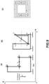
- FIG. 7 an example of a simple one-dimensional attenuator consisting of a single stage is shown ( Fig. 7 ), obviously replicable for several degrees of freedom and several stages, for better attenuation.
- this figure shows a possible specialization of the one-dimensional Folded Pendulum, one-dimensional only for clarity of exposure, to the implementation of an inertial platform, as seismic attenuator.
- FIG. 1 shows, in particular, how the rods constituting the Folded Pendulum have been specialized in such a way as to create an inertial platform ("P") whose central point has the same dynamic properties as point E 1 . Therefore, by selecting the lengths of the rods, the coefficients of elasticity of the joints and the different masses of the components it is possible to implement a single-stage one-dimensional horizontal platform that has the property of inertial mass for frequencies higher than the resonance frequencies of the Folded Pendulum.
- P inertial platform
- Fig. 7 in (b) shows, instead, a platform not rigidly constrained to point E 1 but at the ends of the segment E a E b , which by construction can have a component, although very small by design, in a direction other than x , but always in the plane of the pendulum. Therefore, this platform has a motion that can only be approximated to a linear motion, which however is sufficient for the implementation of platforms controlled with automatic control systems (in feedback), providing the acceleration of the system as output data, according to what discussed above.
- Fig. 7 in (c) shows a one-dimensional platform not constrained to the point E 1 but to the ends of the segment E a E b , wider than that of Fig. 7 (b) , which can be characterized in a similar way and with the same properties.
- points E a and E b can also be not internal to the segment between joints B 1 and C 1 , but external (even one only), and therefore they are positioned along the geometric line that includes joints B 1 and C 1 .
- FIG. 8 An application example 800 of a two-dimensional system that can be used as an inertial platform, but also as a two-dimensional horizontal sensor is presented in Fig. 8 , de facto a direct extension to the two-dimensional case of the typology of system shown as one-dimensional case in Fig. 7 (c) .
- the two-dimensional system shown in Fig. 8 consists, in fact, of two Folded Pendulums, one for each degree of freedom, in turn each consisting of Folded Pendulums (preferably identical) placed side by side and constrained so as to constitute a single Folded Pendulum, thus not modifying in any way what has been said and described above.
- each i -th Folded Pendulum there may be M i ( M i ⁇ 0) further Folded Pendulums, each including a further m i -th support, a further m i -th central arm, a further first arm (or simple arm) m i -th, and a further second arm (or inverted arm) m i -th (with their respective further central joints (of the central arm) and terminals (of the arms connected to the medium) rigidly connected respectively to said i -th support, i -th central arm, i -th first arm (or simple arm), and i -th second arm (or inverted arm) of the N Folded Pendulums illustrated so far.
- This system which in fact can constitute a single stage of a multistage attenuation system, is characterized by two resonance frequencies that are generally different, but which can be made perfectly identical, by means of a suitable combination of the physical geometric parameters and the elasticity of the joints, constituting each pendulum, but also using suitably positioned calibration masses [3, 4, 5, 7, 8, 9].
- a suitable designed feedback control system can change the resonance frequency of the controlled system bringing it to lower or higher values depending on the typology of feedback applied (negative or positive) and, therefore, in the case of the present description, by carrying out a specific calibration procedure of the resonance frequencies of the system.
- central arm any rigid central group, not necessarily linear, with a first and a second end connected to two of said joint systems.
- the two linked points of the above platform are positioned along the geometric segment between the said first and the said second end, obviously in positions coincident with material points of the group, but which may be such as not to have a straight continuation between them.
- the central group starts with a linear part from the two joints, and then changes shape. These two points are placed on the initial straight parts that come out of the joints.
- the term "arm" means that part of a rod or mechanical element between two joints or between a fixed point and a joint, and therefore the length of the arm is meant as the distance between these two points.
- the rod or the mechanical element themselves can actually continue beyond the joint or the fixed point, and in this case the mass of the whole rod affects the position of the center of gravity but not of the geometric center defined as the central point of the arm.
- FIG. 9 shows the typical implementation scheme of folded pendulums aimed at the containment of the dimensions in order to obtain effective and compact mechanisms. Obviously, this scheme can be reiterated for multiple stages of freedom.
- the figure on the right shows a monolithic construction aimed at the reduction of the pendulum size.
- FIG. 10 An application example of a compact two-dimensional system that can be used as an inertial platform, but also as a two-dimensional horizontal sensor 1000 is presented in Fig. 10 , de facto a direct extension to the two-dimensional case of the system typology represented as a one-dimensional case in Fig. 9 (b) according to the invention.
- the two-dimensional system shown consists of two Folded Pendulums, one for each degree of freedom positioned close to each other and rigidly connected, each in turn implemented by means of (preferably) identical Folded Pendulums so as to constitute a single Folded Pendulum, thus not modifying in any way what said and described above.
- each other pendulum there may be M i ( M i ⁇ 0) further one-dimensional pendulums, each including a further m i -th support, a further arm m i -th central arm, a further straight m i -th simple arm, and a further m i -th inverted arm (with their respective further central and i -th terminal joints) rigidly connected respectively to said i -th support, i -th central arm, simple i -th arm, and inverted i -th arm of the N Folded Pendulums illustrated so far.
- This system which in fact can constitute a single stage of a multistage attenuation system, is characterized by two resonance frequencies that are generally different, but which can be made perfectly identical by means of a suitable combination of the physical and geometric parameters and of the elasticity of the joints, constituting the individual pendulums, but also using appropriately positioned calibration masses [3, 4, 5, 7, 8, 9].
- K g eq a key element in determining the resonance frequency of the mechanical oscillator and, therefore, of its mechanical performances, does not depend on the absolute values of the masses that constitute it, but only on the differences in their values.
- a fully modular prototype of a two-dimensional attenuation stage has been implemented as described in figure 10 , with overall dimensions equal to 100 cm x 100 cm x 135 cm (length x width x height), characterized by elliptical elastic joints of different thickness for the two degrees of freedom, made by electro-erosion (EDM) from a single block of Ergal (A1 7075-T6), whose geometric dimensions (30 mm x 40 mm x 200 mm) remain proportional to those used classically in monolithic oscillators made and published in literature (ellipticity ratio 16/5) [7, 8, 9].
- EDM electro-erosion
- the output mechanical signal in this prototype is obtained by means of a readout system based on an optical lever.
- FIG. 11 shows a possible construction scheme of a building 1100 with several floors 1120 and several apartments 1130, 1140 per floor constituted (with the term "building” we mean any structure resting on the ground, including for example hospitals with operating and hospital rooms and anything else necessary), with, for example, an internal staircase 1150.
- buildings we mean any structure resting on the ground, including for example hospitals with operating and hospital rooms and anything else necessary
- an internal staircase 1150 for example, an internal staircase 1150.
- in one or more apartments as many two-dimensional stages, as described above are used connected by the elastic joints (A and D) to a basic structure consisting of the building frame 1110 anchored to the ground, capable of supporting these stages.
- the stages are not shown as in the previous figures, but two apartments 1130, 1140 are highlighted in which these stages can be applied.
- three-dimensional stages also to dampen vertical oscillations.
- the stages in any case, can also be multiple, that is, each direction can have several nested stages.
- FIG 11 in fact, schematically shows the example of a multi-storey building with several apartments per floor.
- a suitable design of the mechanics allows the implementation of apartments (which we recall can be schematized as platforms) that have the possibility of horizontal motion, characterized by very low resonance frequencies (even below mHz) obtainable both directly in the design phase (natural resonance frequency in absence of feedback control systems) and through the use of feedback control systems, which can also be aimed at damping the resonance peak typical of the harmonic response of the system (although generally quite low, since systems with a resonance frequency of the order of or lower than mHz are usually characterized by very low Q).
- This mechanical configuration makes each single apartment in fact insensitive or very little sensitive to seismic stresses in the frequency band higher than its resonant frequency, being in fact an inertial mass in this band.
- a possible application is in the emergency medicine field, with a foreseen possibility of carrying out surgical operations or medical analysis in real time within moving structures, such as, for example, ambulances ( Figure 12 ).
- a correct design of the vertical and horizontal damping stages may allow the creation of a platform inside the ambulance 1200 (which in this case would assume the role of external support; in any case what will be said applies to any vehicle), inertial for frequencies higher than the resonance one of the three degrees of freedom.
- a platform made in this way, being de-coupled from the motion of the vehicle, can be used as a support for carrying out medical operations even on board of a moving vehicle.
- a stage 1250 is highlighted, not in scale, on which to place a medical operation cabin.
- the stage 1250 is positioned on a base 1213, damped through a system 1210 according to the invention, in the example consisting of a double Watt's Linkage. It is specified that the arms are not represented in the scheduled reciprocal dimensions for a better readability of the figure.
- the system 1210 includes a 1212 frame (shown below, but equally applicable above) to which the two Watt's Linkages are connected.
- the two Watt's Linkages are made starting from a single support point 1211 fixed to the vehicle structure through the frame 1212.
- the first Watt's Linkage on the left has a first arm 1214 connected through a joint to the frame 1212, and a second arm 1219 connected to the frame 1212 through a different joint in position 1211.
- the first and second arm are connected by the central arm 1215, to which the base 1213, that supports the stage 1250, is rigidly connected.
- the fixing point E A is not necessarily in the optimal position. Please refer to the above for the different possible placements of point E A , including the option to create two separate points not directly connected to each other, as in Figure 7 .
- the first arm 1217 is connected to the frame 1212 through a joint, while the second arm 1218 is always connected to the frame 1212 but at the point 1211.
- the central arm is the 1216, to which the base 1213 is connected at the point E B .
- the stage 1250 is the equivalent of the apartment in Figure 11 , and, therefore, a system according to the invention can be attached to it, capable of damping horizontal oscillations.
- the stage can be two-dimensional or even three-dimensional to further dampen vertical oscillations.
- the stage in any case, can also be multiple, that is, each direction can have several connected stages.
- the system can benefit from elastic joints for vertical damping (to balance the weight force) or magnetic damping (as in the vertical pendulum of patent EP2643711 B1 ), which can also be used in all the other cases described.
- Another example of application is, instead, that of the reduction of the pitching and rolling motion for the stabilization of holds or cabins in ships, in order to make it easier the reduction of the forcing due to the wave motion as regards the load, or in order to promote well-being on board in the case of passenger cabins.
- the architecture of a cabin (or of a hold, which can however always be divided into several parallel platforms, similarly to the case of the apartments positioned on a single floor in Figure 11 ) can be schematized in a similar way to what has been done in the example relating to the ambulance.
- an application of the invention consists in damping an axle 1300 of a vehicle (not shown).
- a frame consisting of segments 1325, 1326, 1327 is connected to the axis 1320 between two wheels 1310, in one or more points or areas.
- Two opposite arms 1330, 1340 are connected to this frame by means of the corresponding joints 1331 and 1341.
- the two arms 1330 and 1340 are joined, through the corresponding joints 1332, 1342, by a central arm 1350, on which a point 1351 has been represented which is not connected to the axis 1320 but moves in the plane of the figure (x - z axes).
- the axis 1320 is behind the central axis 1350.
- the joints have an axis perpendicular to the figure.
- a second Watt system is applied on point 1351 (or set of points or frame area 1325, 1326, 1327) of the first Watt system.
- a frame consisting of the segments 1328, 1326 and 1329 is fixed at point 1351 of the first Watt system, but it is not connected in any way to the axis 1320 between the wheels 1310. The fact that it appears overlying in the figure is due to the optimal central position of point 1351.
- the first arm 1380 of this second system is rigidly connected to the frame described through the joint 1381, while the second arm 1390 is connected to the frame through the joint 1391.
- the central arm is indicated with the reference 1360 and it is connected to the first and second arm with the respective joints 1382 and 1392.
- the vehicle chassis is connected to a point (or zone, or plurality of points as explained above for the other embodiments) of the central arm 1360.
- the direction of the arms is only schematic, other directions are possible within the same operating principle.
- an additional stage can be added to obtain a three-dimensional system according to the invention, with an additional damping direction.
- the choice of the masses and of the positions aimed at the change of the resonance frequencies of the single stages must be made in a contextual and global way, although this operation is technically simple and fully feasible.
- the use and positioning of suitable calibration masses has allowed the reduction of the resonance frequencies of the system in the two degrees of freedom from 30 mHz to 10 mHz.
- joints referred to in this description can be flexible, since they must constitute a rotational constraint for the arms of the rods of the Watt's Linkage or, as a particular case, of the Folded Pendulum.
- joint The choice of the typology of joint to be used depends on each application, but what must be guaranteed is the best possible definition of the center of rotation relative to the joint itself. Therefore, useful for this purpose is any mechanical system (joint) that is capable to guarantee that two rods connected at the ends (or in another convenient point) rotate around a defined point or in any case very well approximated (center of rotation).
- This constraint can, therefore, be for example a mechanical pin, a bearing (ball bearing, for example) or a circular or elliptical flexible joint, or of any other shape capable of guaranteeing a rotational constraint of two mechanical parts, regardless of whether the constraint operates in traction or in compression, a condition dictated and defined each time by the numerous and possible types of architectures that can be used for the implementation of the mechanisms described and object of this invention.
- the key element is the elasticity of the joint itself, which can be defined in the design phase of the Watt's Linkage/Folded Pendulum.
- These joints can be elastically native such as for example the elliptical and/or circular elastic joints, classically used in the monolithic implementations of one-dimensional Watt's Linkage/Folded Pendulum, or, for example, rotating ball bearings equipped with helical springs which make their dynamic behavior very similar to those of a classic monolithic circular or elliptical joint.
- the design of the joints is in any case always aimed at achieving the requirements relating to the dimensions and elasticity defined in the design phase. Their design and implementation therefore require, from time to time, the choice of the material, the shape, the thickness, as well as the choice of the manufacturing technique (machining by precision numerical milling, by EDM by immersion, etc.). It is possible, as already shown in Figures 8 and 10 , to implement joints operating in pairs or in any case in parallel (also, in general, more than two). The latter technical design choice has, in fact, the advantage of limiting the torsional effects of the joints themselves, minimizing the coupling between the longitudinal and transversal degrees of freedom.
Landscapes
- Physics & Mathematics (AREA)
- General Physics & Mathematics (AREA)
- Engineering & Computer Science (AREA)
- Remote Sensing (AREA)
- Life Sciences & Earth Sciences (AREA)
- Geology (AREA)
- Environmental & Geological Engineering (AREA)
- General Life Sciences & Earth Sciences (AREA)
- Acoustics & Sound (AREA)
- Geophysics (AREA)
- Buildings Adapted To Withstand Abnormal External Influences (AREA)
- Measurement Of Mechanical Vibrations Or Ultrasonic Waves (AREA)
- Gyroscopes (AREA)
Claims (18)
- Mehrdimensionales mechanische Wattgestänge, VLM, umfassend eine Anzahl von N eindimensionalen Wattgestängen mit N = 2,3, wobei das i-te eindimensionale Wattgestänge mit i = 1,.., N so eingeschränkt ist, dass es sich auf einer jeweiligen i-ten Ebene eines dreidimensionalen räumlichen Bezugssystems bewegt, und das umfasst:- eine i-te Stütze (
A 1 D 1 ,A 2 D 2 ,A 3 D 3 );- einen i-ten Mittelarm (B 1 C 1 ,B 2 C 2 ,B 3 C 3) ;- einen i-ten ersten Arm (A 1 B 1 ,A 2 B 2 ,A 3 B 3 );- einen i-ten zweiten Arm (D 1 C 1 ,D 2 C 2 ,D 3 C 3 );wobei der i-te erste Arm und der i-te zweite Arm an einem ihrer Enden mit dem i-ten Mittelarm über entsprechende i-te Mittelverbindungssysteme (B 1,B 2, B 3; C 1 , C 2, C 3) und an ihrem anderen Ende mit der i-ten Stütze über entsprechende i-te Endverbindungssysteme (A 1, A 2, A 3; D 1, D 2, D3) verbunden sind, wobei die entsprechenden Mittel- und Endverbindungssysteme Drehachsen parallel und senkrecht zu der i-ten Ebene aufweisen, wobei der i-te Mittelarm an keinem Punkt an der i-ten Stütze befestigt ist und sich somit relativ zu dieser frei bewegt und wobei die Stütze des i-ten eindimensionalen Wattgestänges mit i = 1 in dem dreidimensionalen räumlichen Bezugssystem befestigt ist;wobei das mehrdimensionale mechanische Wattgestänge, VLM, dadurch gekennzeichnet ist, dass:- der i-te Mittelarm (B 1 C 1, B 2 C 2 ) an mindestens einem Punkt starr mit der i+1-ten Stütze (A 2 D 2 ,A 3 D 3 ) bei i = 1, ..., N-1 verbunden ist;- bei i = 2..., N die i-te Stütze (A 2 D 2 ,A 3 D 3 ) in dem dreidimensionalen räumlichen Bezugssystem beweglich ist;- die i-te Ebene so gewählt ist, dass sie nicht aus einer linearen Kombination der verbleibenden N-1 jeweiligen Ebenen der N eindimensionalen Wattgestänge erhältlich ist. - Mehrdimensionales mechanisches Wattgestänge nach Anspruch 1,
wobei für jedes i-te eindimensionale Wattgestänge M i (Mi ≥ 0) weitere eindimensionale Wattgestänge existieren, wobei das weitere mi -te Wattgestänge bei mi = 1, ..., Mi mit seinen jeweiligen weiteren mi -ten Mittelverbindungen und seinen weiteren mi -ten Endverbindungen eine weitere mi -te Stütze, bei mi = 1, .., Mi einen weiteren mi -ten Mittelarm, einen weiteren mi -ten ersten Arm und einen weiteren mi -ten zweiten Arm umfasst, die starr mit der i-ten Stütze, dem i-ten Mittelarm, dem i-ten ersten Arm bzw. dem i-ten zweiten Arm verbunden sind. - Mehrdimensionales mechanisches Wattgestänge nach Anspruch 2, wobei Mi = 1.
- Mehrdimensionales mechanisches Wattgestänge nach Anspruch 2 oder 3, wobei die weiteren mi -ten Mittel- und Endverbindungssysteme von den i-ten Mittel- und Endverbindungssystemen getrennt sind.
- Mehrdimensionales mechanisches Wattgestänge nach Anspruch 2 oder 3, wobei die weiteren mi -ten Mittel- und Endverbindungssysteme mit den i-ten Mittel- und Endverbindungssystemen der entsprechenden i-ten Wattgestänge zusammenfallen, wodurch einzigartige i-te Mittel- und Endverbindungssysteme bereitgestellt werden, die sich quer zu den jeweiligen Schwingungsebenen der i-ten eindimensionalen Wattgestänge erstrecken.
- Mehrdimensionales mechanisches Wattgestänge nach einem oder mehreren der Ansprüche 1 bis 5, wobei der i-te Mittelarm (
B 1 C 1 ,B 2 C 2 ,B 3 C 3 ) bei i = 1, .., N-1 an mindestens zwei Punkten starr mit der i+1-ten Stütze (A 2 D 2 ,A 3 D 3 ) verbunden ist. - Mehrdimensionales mechanisches Wattgestänge nach Anspruch 6, wobei die beiden Punkte relativ zum geometrischen Mittelpunkt (E1, E2, E3) des i-ten Mittelarms bogensymmetrisch sind.
- Mehrdimensionales mechanisches Wattgestänge nach Anspruch 6 oder 7, wobei der i-te Mittelarm eine starre Mittelanordnung ist, die ein erste sind ein zweites Ende aufweist, die mit den entsprechenden i-ten Mittelverbindungssystemen (B 1 , B 2, B 3; C 1, C 2, C 3) verbunden sind und bei der die beiden Punkte entlang der geometrischen Linie positioniert sind, die das erste und das zweite Ende einschließt.
- Mehrdimensionales mechanisches Wattgestänge nach einem oder mehreren der Ansprüche 1 bis 8, wobei eine Plattform (P), die mit mindestens einem Punkt des N-ten Mittelarms (
B 1 C 1 ,B 2 C 2 ,B 3 C 3 ) und/oder mindestens einem der weiteren mN -ten mittelarme verbunden ist, ferner enthalten ist. - Mehrdimensionales mechanisches Wattgestänge nach Anspruch 9, wobei die beiden Punkte symmetrisch relativ zum geometrischen Mittelpunkt (E 1, E 2, E 3) des i-ten Mittelarms und/oder der mindestens einen weiteren mN -ten Mittelarme sind.
- Mehrdimensionales gefaltetes Pendel, das aus einem mehrdimensionalen mechanischen Wattgestänge nach einem der vorhergehenden Ansprüche besteht, wobei in der Ruheposition der i-te Mittelarm (
B 1 C 1 ,B2C2 ,B 3 C 3 ) sowohl zu dem i-ten ersten Arm (A 1 B 1 ,A 2 B 2 ,A 3 B 3 ) als auch dem i-ten zweiten Arm (D 1 C 1 ,D 2 C 2 ,D 3 C 3 ) senkrecht sind und der mi -te Mittelarm (B 1 C 1 ,B 2 C 2 ,B 3 C 3 ) sowohl zu dem mi -ten ersten Arm (A 1 B 1 ,A 2 B 2 ,A 3 B 3 ) als auch dem mi -ten zweiten Arm (D 1 C 1 ,D 2 C 2 ,D 3 C 3 ) senkrecht ist. - Mehrdimensionales gefaltetes Pendel nach Anspruch 11, wobei das mehrdimensionale gefaltete Pendel aus einem monolithischen Block aus geeignetem bearbeiteten Material besteht.
- Mehrdimensionales gefaltetes Pendel nach einem der Ansprüche 11 oder 12, dadurch gekennzeichnet, dass jedes der Verbindungssysteme zwei Verbindungen umfasst.
- Mehrdimensionales gefaltetes Pendel nach einem der Ansprüche 11 bis 13, dadurch gekennzeichnet, dass die Verbindungssysteme nichtkreisförmige elliptische Verbindungen umfassen.
- Mehrdimensionales gefaltetes Pendel nach Anspruch 14, dadurch gekennzeichnet, dass die Verbindungssysteme zwei Verbindungen umfassen, die durch Entfernen zweier Ellipsen verfolgt werden, die eine Exzentrizität Σ > 3.2 und einen reziproken Abstand d > 10 Mikrometer aufweisen.
- Mehrdimensionales gefaltetes Pendel nach einem oder mehreren der Ansprüche 11 bis 15, wobei jedes Verbindungssystem (A 1, A 2, A 3; B 1, B 2, B 3) relativ zu dem i-ten ersten Arm und/oder zu dem weiteren mi -ten ersten Arm ein oder mehrere Verbindungen in Traktion umfasst.
- Mehrdimensionales gefaltetes Pendel nach einem oder mehreren der Ansprüche 11 bis 16, wobei jedes Verbindungssystem (A 1, A 2, A 3; B 1, B 2, B 3) relativ zu dem i-ten zweiten Arm und/oder dem weiteren mi -ten zweiten Arm ein oder mehrere Verbindungen in Kompression umfasst.
- Seismischer Sensor, umfassend:- ein mehrdimensionales mechanisches Wattgestänge oder ein mehrdimensionales gefaltetes Pendel, das eine Vielzahl von eindimensionalen mechanischen Wattgestängen bzw. mehrdimensionalen gefalteten Pendeln umfasst, die jeweils eine entsprechende Prüfmasse und eine entsprechende Stütze (
A 1 D 1 ,A 2 D 2 ,A 3 D 3 ) aufweisen,- jeweilige Systeme zum Erkennen der scheinbaren Verschiebung der jeweiligen Prüfmasse zu der jeweiligen Stütze (und dadurch gekennzeichnet, dass das mehrdimensionale mechanische Wattgestänge oder das mehrdimensionale gefaltete Pendel das mehrdimensionale mechanische Wattgestänge nach einem oder mehreren der Ansprüche 1 bis 10 oder das mehrdimensionale gefaltete Pendel nach einem oder mehreren der Ansprüche 11 bis 17 ist, wobei die jeweilige Prüfmasse die Masse des jeweiligen Mittelarms oder des jeweiligen Mittelarms der Plattform (P) ist.A 1 D 1 ,A 2 D 2 ,A 3 D 3 ,),
Applications Claiming Priority (1)
| Application Number | Priority Date | Filing Date | Title |
|---|---|---|---|
| IT102021000014417A IT202100014417A1 (it) | 2021-06-03 | 2021-06-03 | Parallelogramma e pendolo ripiegato di Watt multistadio a larga banda in bassa frequenza, e relativo sensore di posizione, velocità ed accelerazione |
Publications (3)
| Publication Number | Publication Date |
|---|---|
| EP4098983A1 EP4098983A1 (de) | 2022-12-07 |
| EP4098983C0 EP4098983C0 (de) | 2023-10-04 |
| EP4098983B1 true EP4098983B1 (de) | 2023-10-04 |
Family
ID=77519621
Family Applications (1)
| Application Number | Title | Priority Date | Filing Date |
|---|---|---|---|
| EP22175640.6A Active EP4098983B1 (de) | 2021-06-03 | 2022-05-26 | Zwei- oder dreidimensionales wattgestänge und die implementierung in einen seismischen sensor |
Country Status (2)
| Country | Link |
|---|---|
| EP (1) | EP4098983B1 (de) |
| IT (1) | IT202100014417A1 (de) |
Family Cites Families (10)
| Publication number | Priority date | Publication date | Assignee | Title |
|---|---|---|---|---|
| JPS549912B2 (de) | 1972-09-22 | 1979-04-28 | ||
| JPS59163137A (ja) | 1983-03-02 | 1984-09-14 | アンリツ株式会社 | プライスラベラの制御盤 |
| DE3428159C2 (de) * | 1984-07-31 | 1986-09-18 | Daimler-Benz Ag, 7000 Stuttgart | Achsaufhängung für Kraftfahrzeuge, insbesondere Personenkraftwagen |
| AU2696P (en) | 2003-07-31 | 2005-03-09 | Ball Horticultural Co | Balcoldepi Pelargonium peltatum |
| DE102008002697A1 (de) * | 2008-06-27 | 2009-12-31 | Zf Friedrichshafen Ag | Aufhängungseinrichtung mit aktivem Wattgestänge |
| IT1394612B1 (it) | 2009-07-07 | 2012-07-05 | Univ Degli Studi Salerno | Pendolo ripiegato a bassa frequenza con elevato fattore di qualita' meccanico, e sensore sismico utilizzante tale pendolo ripiegato. |
| TWI688047B (zh) | 2010-08-06 | 2020-03-11 | 半導體能源研究所股份有限公司 | 半導體裝置 |
| ITRM20110220A1 (it) | 2011-04-28 | 2012-10-29 | Univ Degli Studi Salerno | Pendolo ripiegato con bassa frequenza di risonanza ed alto fattore di qualità meccanico in configurazione verticale, e sensore sismico verticale utilizzante tale pendolo ripiegato. |
| EP3177888B1 (de) | 2014-08-06 | 2021-06-16 | Universitá Degli Studi Di Salerno | Verfahren zur messung winkel und/oder linearer verschiebungen mit einem oder mehreren gefalteten pendeln |
| IT201800007873A1 (it) | 2018-08-06 | 2020-02-06 | Università degli Studi di Salerno | Metodo per la lavorazione di lamine e giunti elastici sottili, in particolare per la realizzazione di oscillatori meccanici monolitici |
-
2021
- 2021-06-03 IT IT102021000014417A patent/IT202100014417A1/it unknown
-
2022
- 2022-05-26 EP EP22175640.6A patent/EP4098983B1/de active Active
Also Published As
| Publication number | Publication date |
|---|---|
| IT202100014417A1 (it) | 2022-12-03 |
| EP4098983A1 (de) | 2022-12-07 |
| EP4098983C0 (de) | 2023-10-04 |
Similar Documents
| Publication | Publication Date | Title |
|---|---|---|
| US8616054B2 (en) | High-resolution digital seismic and gravity sensor and method | |
| Parida et al. | Double-L cantilever-based fiber Bragg grating accelerometer | |
| US6826960B2 (en) | Triaxial acceleration sensor | |
| US8950263B2 (en) | Low frequency folded pendulum with high mechanical quality factor, and seismic sensor utilizing such a folded pendulum | |
| US9256000B2 (en) | Low frequency folded pendulum and vertical seismic sensor utilizing such a folded pendulum | |
| AU2012247104A1 (en) | Low frequency folded pendulum and vertical seismic sensor utilizing such a folded pendulum | |
| Robertson et al. | Passive and active seismic isolation for gravitational radiation detectors and other instruments | |
| EP4098983B1 (de) | Zwei- oder dreidimensionales wattgestänge und die implementierung in einen seismischen sensor | |
| Konstantinov et al. | Dynamic methods of damping the oscillation in structure–free-surface fluid system | |
| Li et al. | Microseismic observation enabled by high-sensitivity micromechanical interferometers | |
| RU2562273C2 (ru) | Стенд для измерения массо-инерционных характеристик изделия | |
| Acernese et al. | A Michelson interferometer for seismic wave measurement: theoretical analysis and system performances | |
| WEBSTER et al. | Modelling beam-like space trusses with nonlinear joints | |
| EP4357738B1 (de) | Richtungssensor für messung von infraschall, und korrespondierende sender | |
| Ye et al. | Simulation for stability of a beam-mass based high-resolution MEMS gravimeter | |
| Magrab | Thin Beams: Natural Frequencies and Mode Shapes | |
| Barone et al. | Mechanical monolithic compact sensors for real-time linear and angular broadband low frequency monitoring and control of spacecrafts and satellites | |
| Acernese et al. | Mechanical monolithic accelerometer for suspension inertial damping and low frequency seismic noise measurement | |
| Barone et al. | Compact inertial triaxial monolithic sensors for low-frequency acceleration measurement of spacecrafts and satellites | |
| Nelson et al. | Optomechanical Inertial Sensors | |
| Barone et al. | Low frequency motion measurement of spacecrafts and satellites with inertial monolithic sensors | |
| Barlow | Modeling and ground modal identification of space structures | |
| Cella et al. | Suspension for the low frequency facility | |
| Barone et al. | Monolithic sensors for low frequency motion measurement and control of spacecrafts and satellites | |
| Zhang et al. | Design and Simulation of a New Vibration Frequency Sensor with Double Equal Strength Cantilever Beam Fiber Grating |
Legal Events
| Date | Code | Title | Description |
|---|---|---|---|
| PUAI | Public reference made under article 153(3) epc to a published international application that has entered the european phase |
Free format text: ORIGINAL CODE: 0009012 |
|
| STAA | Information on the status of an ep patent application or granted ep patent |
Free format text: STATUS: THE APPLICATION HAS BEEN PUBLISHED |
|
| AK | Designated contracting states |
Kind code of ref document: A1 Designated state(s): AL AT BE BG CH CY CZ DE DK EE ES FI FR GB GR HR HU IE IS IT LI LT LU LV MC MK MT NL NO PL PT RO RS SE SI SK SM TR |
|
| STAA | Information on the status of an ep patent application or granted ep patent |
Free format text: STATUS: REQUEST FOR EXAMINATION WAS MADE |
|
| 17P | Request for examination filed |
Effective date: 20230406 |
|
| RBV | Designated contracting states (corrected) |
Designated state(s): AL AT BE BG CH CY CZ DE DK EE ES FI FR GB GR HR HU IE IS IT LI LT LU LV MC MK MT NL NO PL PT RO RS SE SI SK SM TR |
|
| GRAP | Despatch of communication of intention to grant a patent |
Free format text: ORIGINAL CODE: EPIDOSNIGR1 |
|
| STAA | Information on the status of an ep patent application or granted ep patent |
Free format text: STATUS: GRANT OF PATENT IS INTENDED |
|
| RIC1 | Information provided on ipc code assigned before grant |
Ipc: G01P 15/03 20060101ALI20230428BHEP Ipc: G01V 1/18 20060101ALI20230428BHEP Ipc: G01P 15/08 20060101ALI20230428BHEP Ipc: G01H 1/00 20060101AFI20230428BHEP |
|
| INTG | Intention to grant announced |
Effective date: 20230519 |
|
| GRAS | Grant fee paid |
Free format text: ORIGINAL CODE: EPIDOSNIGR3 |
|
| GRAA | (expected) grant |
Free format text: ORIGINAL CODE: 0009210 |
|
| STAA | Information on the status of an ep patent application or granted ep patent |
Free format text: STATUS: THE PATENT HAS BEEN GRANTED |
|
| RIN1 | Information on inventor provided before grant (corrected) |
Inventor name: ROMANO, ROCCO Inventor name: BARONE, FABRIZIO |
|
| AK | Designated contracting states |
Kind code of ref document: B1 Designated state(s): AL AT BE BG CH CY CZ DE DK EE ES FI FR GB GR HR HU IE IS IT LI LT LU LV MC MK MT NL NO PL PT RO RS SE SI SK SM TR |
|
| REG | Reference to a national code |
Ref country code: GB Ref legal event code: FG4D |
|
| REG | Reference to a national code |
Ref country code: CH Ref legal event code: EP |
|
| REG | Reference to a national code |
Ref country code: IE Ref legal event code: FG4D |
|
| REG | Reference to a national code |
Ref country code: DE Ref legal event code: R096 Ref document number: 602022000627 Country of ref document: DE |
|
| U01 | Request for unitary effect filed |
Effective date: 20231009 |
|
| U07 | Unitary effect registered |
Designated state(s): AT BE BG DE DK EE FI FR IT LT LU LV MT NL PT SE SI Effective date: 20231016 |
|
| PG25 | Lapsed in a contracting state [announced via postgrant information from national office to epo] |
Ref country code: GR Free format text: LAPSE BECAUSE OF FAILURE TO SUBMIT A TRANSLATION OF THE DESCRIPTION OR TO PAY THE FEE WITHIN THE PRESCRIBED TIME-LIMIT Effective date: 20240105 |
|
| PG25 | Lapsed in a contracting state [announced via postgrant information from national office to epo] |
Ref country code: IS Free format text: LAPSE BECAUSE OF FAILURE TO SUBMIT A TRANSLATION OF THE DESCRIPTION OR TO PAY THE FEE WITHIN THE PRESCRIBED TIME-LIMIT Effective date: 20240204 |
|
| U20 | Renewal fee for the european patent with unitary effect paid |
Year of fee payment: 3 Effective date: 20240321 |
|
| PG25 | Lapsed in a contracting state [announced via postgrant information from national office to epo] |
Ref country code: ES Free format text: LAPSE BECAUSE OF FAILURE TO SUBMIT A TRANSLATION OF THE DESCRIPTION OR TO PAY THE FEE WITHIN THE PRESCRIBED TIME-LIMIT Effective date: 20231004 |
|
| PG25 | Lapsed in a contracting state [announced via postgrant information from national office to epo] |
Ref country code: IS Free format text: LAPSE BECAUSE OF FAILURE TO SUBMIT A TRANSLATION OF THE DESCRIPTION OR TO PAY THE FEE WITHIN THE PRESCRIBED TIME-LIMIT Effective date: 20240204 Ref country code: GR Free format text: LAPSE BECAUSE OF FAILURE TO SUBMIT A TRANSLATION OF THE DESCRIPTION OR TO PAY THE FEE WITHIN THE PRESCRIBED TIME-LIMIT Effective date: 20240105 Ref country code: ES Free format text: LAPSE BECAUSE OF FAILURE TO SUBMIT A TRANSLATION OF THE DESCRIPTION OR TO PAY THE FEE WITHIN THE PRESCRIBED TIME-LIMIT Effective date: 20231004 |
|
| PG25 | Lapsed in a contracting state [announced via postgrant information from national office to epo] |
Ref country code: RS Free format text: LAPSE BECAUSE OF FAILURE TO SUBMIT A TRANSLATION OF THE DESCRIPTION OR TO PAY THE FEE WITHIN THE PRESCRIBED TIME-LIMIT Effective date: 20231004 Ref country code: PL Free format text: LAPSE BECAUSE OF FAILURE TO SUBMIT A TRANSLATION OF THE DESCRIPTION OR TO PAY THE FEE WITHIN THE PRESCRIBED TIME-LIMIT Effective date: 20231004 Ref country code: NO Free format text: LAPSE BECAUSE OF FAILURE TO SUBMIT A TRANSLATION OF THE DESCRIPTION OR TO PAY THE FEE WITHIN THE PRESCRIBED TIME-LIMIT Effective date: 20240104 Ref country code: HR Free format text: LAPSE BECAUSE OF FAILURE TO SUBMIT A TRANSLATION OF THE DESCRIPTION OR TO PAY THE FEE WITHIN THE PRESCRIBED TIME-LIMIT Effective date: 20231004 |
|
| REG | Reference to a national code |
Ref country code: DE Ref legal event code: R097 Ref document number: 602022000627 Country of ref document: DE |
|
| PG25 | Lapsed in a contracting state [announced via postgrant information from national office to epo] |
Ref country code: CZ Free format text: LAPSE BECAUSE OF FAILURE TO SUBMIT A TRANSLATION OF THE DESCRIPTION OR TO PAY THE FEE WITHIN THE PRESCRIBED TIME-LIMIT Effective date: 20231004 |
|
| PG25 | Lapsed in a contracting state [announced via postgrant information from national office to epo] |
Ref country code: SK Free format text: LAPSE BECAUSE OF FAILURE TO SUBMIT A TRANSLATION OF THE DESCRIPTION OR TO PAY THE FEE WITHIN THE PRESCRIBED TIME-LIMIT Effective date: 20231004 |
|
| PG25 | Lapsed in a contracting state [announced via postgrant information from national office to epo] |
Ref country code: SM Free format text: LAPSE BECAUSE OF FAILURE TO SUBMIT A TRANSLATION OF THE DESCRIPTION OR TO PAY THE FEE WITHIN THE PRESCRIBED TIME-LIMIT Effective date: 20231004 Ref country code: SK Free format text: LAPSE BECAUSE OF FAILURE TO SUBMIT A TRANSLATION OF THE DESCRIPTION OR TO PAY THE FEE WITHIN THE PRESCRIBED TIME-LIMIT Effective date: 20231004 Ref country code: RO Free format text: LAPSE BECAUSE OF FAILURE TO SUBMIT A TRANSLATION OF THE DESCRIPTION OR TO PAY THE FEE WITHIN THE PRESCRIBED TIME-LIMIT Effective date: 20231004 Ref country code: CZ Free format text: LAPSE BECAUSE OF FAILURE TO SUBMIT A TRANSLATION OF THE DESCRIPTION OR TO PAY THE FEE WITHIN THE PRESCRIBED TIME-LIMIT Effective date: 20231004 |
|
| PLBE | No opposition filed within time limit |
Free format text: ORIGINAL CODE: 0009261 |
|
| STAA | Information on the status of an ep patent application or granted ep patent |
Free format text: STATUS: NO OPPOSITION FILED WITHIN TIME LIMIT |
|
| 26N | No opposition filed |
Effective date: 20240705 |
|
| PG25 | Lapsed in a contracting state [announced via postgrant information from national office to epo] |
Ref country code: MC Free format text: LAPSE BECAUSE OF FAILURE TO SUBMIT A TRANSLATION OF THE DESCRIPTION OR TO PAY THE FEE WITHIN THE PRESCRIBED TIME-LIMIT Effective date: 20231004 |
|
| PG25 | Lapsed in a contracting state [announced via postgrant information from national office to epo] |
Ref country code: MC Free format text: LAPSE BECAUSE OF FAILURE TO SUBMIT A TRANSLATION OF THE DESCRIPTION OR TO PAY THE FEE WITHIN THE PRESCRIBED TIME-LIMIT Effective date: 20231004 |
|
| PG25 | Lapsed in a contracting state [announced via postgrant information from national office to epo] |
Ref country code: IE Free format text: LAPSE BECAUSE OF NON-PAYMENT OF DUE FEES Effective date: 20240526 |
|
| U20 | Renewal fee for the european patent with unitary effect paid |
Year of fee payment: 4 Effective date: 20250324 |
|
| PG25 | Lapsed in a contracting state [announced via postgrant information from national office to epo] |
Ref country code: HU Free format text: LAPSE BECAUSE OF FAILURE TO SUBMIT A TRANSLATION OF THE DESCRIPTION OR TO PAY THE FEE WITHIN THE PRESCRIBED TIME-LIMIT; INVALID AB INITIO Effective date: 20220526 |
|
| PG25 | Lapsed in a contracting state [announced via postgrant information from national office to epo] |
Ref country code: CY Free format text: LAPSE BECAUSE OF FAILURE TO SUBMIT A TRANSLATION OF THE DESCRIPTION OR TO PAY THE FEE WITHIN THE PRESCRIBED TIME-LIMIT; INVALID AB INITIO Effective date: 20220526 |
|
| REG | Reference to a national code |
Ref country code: CH Ref legal event code: H13 Free format text: ST27 STATUS EVENT CODE: U-0-0-H10-H13 (AS PROVIDED BY THE NATIONAL OFFICE) Effective date: 20251223 |
|
| PG25 | Lapsed in a contracting state [announced via postgrant information from national office to epo] |
Ref country code: CH Free format text: LAPSE BECAUSE OF NON-PAYMENT OF DUE FEES Effective date: 20250531 |