EP4357738B1 - Richtungssensor für messung von infraschall, und korrespondierende sender - Google Patents
Richtungssensor für messung von infraschall, und korrespondierende sender Download PDFInfo
- Publication number
- EP4357738B1 EP4357738B1 EP23192946.4A EP23192946A EP4357738B1 EP 4357738 B1 EP4357738 B1 EP 4357738B1 EP 23192946 A EP23192946 A EP 23192946A EP 4357738 B1 EP4357738 B1 EP 4357738B1
- Authority
- EP
- European Patent Office
- Prior art keywords
- arm
- support
- displacement
- watt
- central
- Prior art date
- Legal status (The legal status is an assumption and is not a legal conclusion. Google has not performed a legal analysis and makes no representation as to the accuracy of the status listed.)
- Active
Links
Images


Classifications
-
- G—PHYSICS
- G01—MEASURING; TESTING
- G01H—MEASUREMENT OF MECHANICAL VIBRATIONS OR ULTRASONIC, SONIC OR INFRASONIC WAVES
- G01H3/00—Measuring characteristics of vibrations by using a detector in a fluid
-
- G—PHYSICS
- G10—MUSICAL INSTRUMENTS; ACOUSTICS
- G10K—SOUND-PRODUCING DEVICES; METHODS OR DEVICES FOR PROTECTING AGAINST, OR FOR DAMPING, NOISE OR OTHER ACOUSTIC WAVES IN GENERAL; ACOUSTICS NOT OTHERWISE PROVIDED FOR
- G10K9/00—Devices in which sound is produced by vibrating a diaphragm or analogous element, e.g. fog horns, vehicle hooters or buzzers
- G10K9/18—Details, e.g. bulbs, pumps, pistons, switches or casings
- G10K9/22—Mountings; Casings
Definitions
- the present invention relates to a mechanical sensor aimed at measuring low-frequency broadband acoustic signals (infrasound) propagating in liquid and gaseous media for scientific, civil and industrial applications, and a complementary mechanical emitter (source) for acoustic signals emission in analogous band.
- a typical example of wave propagation of signals generated by local events is represented by seismic waves generated by earthquakes. More in detail, the local ground displacement generated by an earthquake produces signals propagating in depth and/or on the surface as waves over great distances at the typical speed of the supporting medium through compressions and rarefactions. Therefore, a suitably positioned sensor arrays may allow the reconstruction of the signal and the localization of the generating phenomenon also at great distances.
- a physical quantity measurable by sensors is the local displacement over the time of a generic point of the ground affected by the arrival of the seismic wave, regardless of the type of wave.
- sensors can be used, including, for example, inertial seismometers. These sensors measure the absolute motion of the point to which they are integral (measuring point) with respect to the motion of an inertial mass, the basic element of the seismometer itself, implemented in classic inertial seismometers as mechanical oscillator.
- the mechanical signal propagates with speed depending on the medium through compressions and rarefactions, which determine local pressure changes, that in most cases is the physical quantity used in measurement of the mechanical signal.
- the absolute motion of a fixed reference point generated by the pressure change in the medium induced by the mechanical signal
- a sensor integral to the ground in this point, measures the relative displacement between the position of the fixed reference point and the position of the mechanic mass of its oscillator.
- This measurement provides the absolute motion of the fixed reference point for frequencies higher than the resonance frequency of the mechanical oscillator itself [4, 5, 6], which coupled with the knowledge of the type of solid medium allows to trace the pressures generating this signal.
- these sensors are also called geophones in the field of geophysics.
- the pressure changes should be measured at a fixed point, but since the sensor cannot be integral to the fluid medium (e.g. air), it is generally integral a different point (e.g. ground).
- the fluid medium e.g. air
- the sensor cannot be integral to the fluid medium (e.g. air)
- it is generally integral a different point (e.g. ground).
- This type of measurement configuration obliged by the not solid typology of the medium, allows the measurement of pressure change, carried out at the point where the transducer is present, but relative to the point to which the sensor is physically integral. It is therefore evident that in the specific case of a sensor integral to the ground, the seismic signal becomes part of the measurement itself, assuming in this case the role of noise.
- this sensor takes the name of hydrophone in liquids (e.g. water) and microphone in gases (e.g. air).
- the pressure waves mentioned above are called acoustic waves and they are generally classified in literature into three frequency bands, the definition of which is related to the sensitivity of the human ear: infrasound ( ⁇ 20 Hz), sound (20 Hz - 20 kHz) and ultrasound (> 20 kHz).
- a sensor can be defined in a schematic and modular way, divided into common components for functionality, even if often made according to very different technologies, which contribute to determine its quality and characteristics in terms of bandwidth and sensitivity, as well as directivity and applicability to specific measurement conditions.
- a microphone is a device - a transducer - which converts pressure changes propagating as pressure waves into an electrical signal.
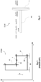
- a microphone consists of a sensitive mechanical element which converts the pressure changes in the medium into mechanical movement (usually a diaphragm), a transducer which converts the mechanical movement into an electrical signal, a container which has different functions depending on the type of microphone and often an input signal filtering system (windscreen) ( Fig. 1 ).
- the microphone there is an element often known as a capsule, which contains the element (diaphragm) properly sensitive to vibrations.
- This sensitive element is the most important component as it determines the microphone sensitivity, bandwidth and directivity, even if the latter can be optimized with suitable mechanical solutions.
- the diaphragm is a mechanical membrane oscillator generally made of a thin steel plate which vibrates in presence of external pressure variations.
- the coefficient of elasticity and the mass of this membrane determine the mechanical resonance frequency of the system, in a completely analogous way to what happens for a classic mass-spring mechanical oscillator, effectively defining sensitivity, measurement band (in commercial microphones the band measurement rarely extends below 1 Hz) and directivity of the microphone itself.
- considerable technological developments have been made aimed, however, more at the miniaturization of microphones than at extending the measurement band in the infrasound region.
- MEMS-based microphones [8], variants of the classic condenser microphone, are characterized by the fact that the pressure-sensitive diaphragm is etched directly into a silicon wafer and usually accompanied by an integrated preamplifier.
- the high quality of the constructions improves the signal-to-noise ratio, a widening of the measurement band in the low frequency region (infrasound) is difficult to predict for this type of microphone.
- Very low frequency sensors based on the Watt-linkage mechanism are also known [19,20] which are not structured to work as acoustic sensors.
- multidimensional force sensors with a rod system are known [21] but are not suitable for use as acoustic sensors.
- the object of the present invention is to provide a method for measuring a low-frequency broadband external stress, generated, for example, by mechanical pressure waves propagating in liquids and gases for civil and industrial scientific applications, which in whole or in part solves the problems and overcome the drawbacks of the prior art, and of an emitter of external stresses, for example of pressure waves, which operates in the same band.
- the object of the present invention is a method for measuring an external stress, as well as a mechanical sensor and emitter of mechanical pressure waves according to the attached claims.
- Two or more of the parts (elements, devices, systems) described according to the invention can be freely associated and considered as a kit of parts according to the invention.
- An optimal solution which solves the problems which limit the realization of high-quality low frequency microphones, is, according to the invention, that of replacing the mechanical oscillator (diaphragm, capsule, etc.) with a highly directive mechanical oscillator characterized by a very low resonance frequency, forced by pressure variations (signals) through a mechanical system aimed at optimizing the coupling with the external pressure signal.
- the invention described here introduces, in fact, a new type of microphone, based on a technologically innovative mechanism, such as that based on the Watt's Linkage [9], a kinematic mechanism which has undergone various developments and applications over the last few years, among which there is its Folded Pendulum version [10].
- This new vision and structure of a microphone sensitive to infrasound allows, as we will see in the following description, the theoretical and experimental resolution of most of the problems that have prevented the realization of high-quality microphones in terms of sensitivity and directivity in the low frequency region (bandwidth characterized by frequency ⁇ 0.1 Hz),
- the innovative architecture introduced with the present invention, will make possible the realization of native directional one-dimensional microphones with high sensitivity, high directivity and wide band in the low frequency region, among which microphones for infrasound, and, in a complementary way, high quality sources of infrasound are included and cited by way of example only.
- Equation 12 allowing to interpret the whole system as a system characterized by two inputs ( X f ( s ) and N c ( s )) and only one measurable output, ⁇ X ( s ), is the base for the construction of horizontal seismometers based on the Folded Pendulum architecture, probably the best known and most widespread application of this technology in literature.
- Equation 16 allows to highlight the dynamic behavior of the seismometer, being the transfer function H ( s ) (defined by Equation 13) the key to understanding this relationship.
- H ( s ) defined by Equation 13
- the quantity ⁇ X ( s ) tends in turn to X g ( s ) ( X g ( s ) ⁇ ⁇ X ( s )) and, as consequence, the measured signal tends to the value of the seismic signal. From a physical point of view this means that as the frequency increases, the displacements X g ( s ) of the base of the Folded Pendulum induce smaller and smaller displacements X c ( s ) in the central mass. In this frequency band, therefore, the central mass can be considered with good approximation an inertial mass.
- Equation 14 shows that the Folded Pendulum can be considered a system with two inputs, one of which is the motion of the base, X f ( s ), and the other is the noise, N c ( s ), which is tried to be reduced in all applications, or in any case to use this input for the introduction of a feedback signal.
- this input as a measurement input, like the other input (the one related to the base (rod AD )) makes the Folded Pendulum system interpretable as a differential mechanical amplifier (differential sensor), allowing the resolution of relevant technological problems, such as for example that of the construction of microphones for acoustic measurements in the infrasound region.
- the atmospheric pressure changes which is the signal to be measured, will be coupled to this system, and in particular to the rod BC , used as the second measurement input, by means of a suitable coupling system (transducer).
- Equation 18 is in fact an equation in two unknowns, X f ( s ) and F c ( s ), since all the other physical and mechanical quantities characterizing the Folded Pendulum are known from the project and/or from calibration, the quantity ⁇ X ( s ) measurable and the input noise, N c ( s ), negligible, or in any case limiting the performance of the system by defining its experimental sensitivity.
- Figure 5(d) shows, instead, the schematization of the Folded Pendulum as a differential mechanical amplifier, in which the forcing, F c ( s ), was expressed in terms of displacement of the central rod, X F c ( s ), due to forcing, in a way congruent to that of the base, X f ( s ), so as to highlight its characteristic of differential mechanical amplifier, as expressed by Equation 18 itself.
- the model is in no way limited by the reading technique of the output signal ⁇ x ( t ), not object of the present invention.
- any technique known in literature as long as it satisfies the required reading precision of the mechanical signal in the design band, can be used.
- the mechanical system described here and object of the present invention is ultimately limited by its thermal noise, as, moreover, well described and reported in the literature [6, 7], to which noises of a different nature can generally be added due to the coupling of the system with the environment, to the interfacing electronics, etc. [14].
- This sensor actually consists of a mechanical membrane oscillator (generally a thin steel plate), which vibrates in presence of external pressure changes, generating a mechanical signal which is converted into an electrical signal by means of a classic coil-magnet transducer ( Fig. 1 ).
- the membrane is stressed by a force proportional to the difference between the pressures insisting on the two sides of the membrane itself, p 1 ( t ) e p 2 ( t ), and to its surface, S, which elastically deforms it by an amount ⁇ x ( t ), quantity measurable by means of a reading system (transducer) of suitable sensitivity and bandwidth, generally of coil-magnet type.
- the microphone makes it possible to carry out relative measurements between the two pressures insisting on the two sides of the membrane, one of which can be chosen as a reference.
- the reference pressure can be defined by isolating one of the two sides of the membrane against external pressure variations.
- p 1 ( t ) variable external pressure
- the invention presented here is instead based on a completely different concept.
- the membrane system of the classic microphone is replaced by a "differential mechanical amplifier", coupled to a pressure/force transduction system, which overcomes the problems and limits of sensitivity and of harmonic response in the low frequency region of currently existing microphones.
- the invention can be framed according to the "differential mechanical amplifier” scheme, which has a displacement input and a force input, the latter being the physical quantity to be measured in a relative or absolute way, whose output signal is expressed by Equation 18.
- the second input is instead the input of the force to be measured, F c ( t ), which in the case of an acoustic sensor (microphone) is the external pressure change (but the approach is applicable, in general, to any type of force).
- a mechanical pressure transducer for example
- This transducer consists of a flat plate (preferably rigid) of area S, the shape of which depends on the specific applications, but which in our description we consider circular for simplicity.
- This force is applied to the central rod BC by means of a rigid (preferably) or non-rigid connection, of any shape and structure, which makes the transducer connected (preferably rigidly and integrally) with the central rod itself, making sure that the force to be measured, F c ( t ), is preferably oriented parallel to the direction of motion of the geometric center E of this rod.
- a rigid (preferably) or non-rigid connection of any shape and structure, which makes the transducer connected (preferably rigidly and integrally) with the central rod itself, making sure that the force to be measured, F c ( t ), is preferably oriented parallel to the direction of motion of the geometric center E of this rod.
- the motion of point E is characterized, by geometric construction and for small displacements, by linear motion described by the vector x f ( t ).
- This choice allows to maximize the coupling (and, therefore, the sensitivity of the instrument) and, at the same time, also maximize the directivity properties of the sensor itself. It is important to underline that if the applied force, F c ( t ), is not parallel to the direction of motion of point E, the system will be forced only by the projection of this force along this direction.
- the real force applied, F c ( t ) can be obtained trigonometrically, once the angle of projection is known.
- the connecting rod AR (or also "transmission arm ") between the plate can be rigidly fixed not only at the optimal point E ( Figure 7(a) ), but at any point of the rod BC inside the rotation joints B and C (e.g. Figure 7(b) ) and outside ( Figure 7(c) ).
- the choice determines the directivity of the final instrument, since, as previously discussed, with the exception of the point E which describes a straight line (maximum directivity), all the other points of the rod BC describe Bernoulli lemniscates with more or less amplitude.
- the introduction of a mechanical pressure transducer to be rigidly connected to the central rod BC can determine a change of the resonance frequency of the original Folded Pendulum.
- the mechanical transducer can be globally assimilated to a mass positioned on the rod BC at the connection point.
- this mass can be considered a calibration mass, m t , whose positioning, as seen previously, has effects on the resonance frequency of the Folded Pendulum (Equations 1-7) since it generally changes the value of the equivalent gravitational spring constant, K g eq , (Equation 8) and of the equivalent mass, M eq , (Equation 10), quantities that determine the resonance frequency of the Folded Pendulum (Equation 7).
- Plate S can be for example a capacitor plate with a coil or magnet, and then the sensor would measure an external stress created across the coil or magnet.
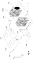
- Figure 8 shows the scheme of principle of the realization of a microphone using a classic monolithic configuration of Folded Pendulum SER ( Fig. 8(a) in schematized form, Fig. 8(b) in lateral realistic form, Fig. 8(c) in frontal realistic form), present in the literature, however used for the realization of the prototype described below.
- the monolithic configuration for classic SERM applications generally does not require the physical presence of point E, which is in fact virtual in the present case.
- the separation membrane is not in principle strictly necessary as it is possible to create external structures in which the external container and the plate S are not in contact, but the propagation of the pressure changes from external to internal and/or vice versa can be made very slow by shaping the surface of the plate such as to make not very effective even the relative slow changes of external pressure with respect to the internal one (for example a shape with edges folded over the volume of the container, thus decreasing the air passage volumes and attenuating the pressure changes on the other side of the surface).
- the pressure p o can be any pressure, being in the example case classically atmospheric pressure, but even zero pressure, indicative of the fact that a vacuum is created in the internal volume.
- any seismic sensor (seismometer, accelerometer, etc.) present in literature or commercially available rigidly connected to the base AD of the Folded Pendulum, which is able to measure in general x f ( t ) and, in the specific case x g ( t ), with sensitivity and bandwidth characteristics compatible with the Folded Pendulum ones, or in any case made such by preliminary processing of the acquired data.
- the most effective way to carry out acoustic noise measurements independent from the local seismic noise is to couple an acoustic sensor as described above (indicated in the figure with the reference SERM) and a classical seismic sensor (indicated in figure with the reference SS), in which the Folded Pendulum is preferably identical to the acoustic sensors Folded Pendulum, so as to ensure identical performance as much as possible, and in particular, resonance frequency and sensitivity.
- SERM acoustic sensor as described above
- SS classical seismic sensor
- a (super)attenuator can be provided on which the sensor according to the invention is positioned.
- the second oscillator SS is made integral to the same plane (or reference) P to which the first oscillator is integral (or even to the same base block AD ) as the first oscillator), but it is totally enclosed in a container (not shown) in such a way that the central mass is not subject to any external forcing due to pressure variations.
- this second configuration is the classic one of inertial seismometers based on Folded Pendulum technology present in the literature.
- the acoustic sensor can optionally be included in its own container but in such a way that the surface S (or other means of pressure transduction) is in any case in contact with the environment external to the sensor/container.
- the container can be the same for both oscillators, but with the surface S always in contact with the outside.
- Reading means 310, 320 of the test mass in both oscillators are respectively provided, as well as a processing unit 210 to which the signals measured by the reading means arrive at the respective inputs 213, 214.
- the outputs 211 and 212 of the processing 210 are respectively those of the seismic signal and of the acoustic signal.
- Equation 24 using the signal measured by the first sensor (SERM microphone), ⁇ X( s ), and the seismic signal measured by the second sensor (SS seismometer), X g ( s ), after compensation of the effects due to possible manufacturing differences (e.g. resonance frequency, reading system gain, etc.) following preventive calibration of the two mechanical oscillators.
- This operation compensating the seismic noise by a cancellation technique, allows the realization of very broadband low-frequency acoustic sensors (band limited by the mechanical resonance frequency of the oscillator) with mechanical sensitivity defined only by the thermal noise of the Watt's Linkage kinematism [7]. For the sake of completeness, it is also possible to cancel the residual noise due to the presence of air inside the container, which would effectively become a vacuum container.
- the signal at 212 may already be the acoustic signal without the seismic component.
- this innovative dual differential system also allows the cancellation (or at least the reduction) of the external couplings which could limit the performance of the sensor (e.g. temperature changes, mechanical aging of the oscillators, etc.), since being the two sensors made with construction methods aimed precisely at this purpose, have characteristics which, by construction, change in a similar way when exposed to the same external causes.
- this invention allows the realization of an innovative sound measurement system, with sensitivity and bandwidth characteristics, in particular, in the infrasound region, which currently constitute a challenge that cannot be achieved with the methodologies and techniques present in the literature and whose limits are no longer determined by mechanics, but only by the quality of the mechanical signal reading system, for which there is a wide choice in terms of sensitivity and techniques in the scientific and/or commercial fields.
- signal transduction systems readout
- the invention described here can also work with the multidimensional oscillator/s referred to in patent application EP 22175640.6 , where it is preferable to make the mechanism with very light materials so as not to lose sensitivity.
- the external pendulum has a necessarily greater test mass than the increasingly internal ones.
- three sensors can be suitably oriented for a measurement in the three spatial directions.
- the sensor described above can also operate without the container illustrated, for example with a sufficiently large plate (in general, its surface can be circular or have any other shape).
- the pressure signal is applied to only one side of the surface similar to what actually happens for the human ear.
- the pressure is kept constant, for example to the average value of the atmospheric pressure.
- any change of the pressure inside the container even in the long term (i.e. so slow to be outside the measurement band of the sensor according to the specific application) generates an offset in the output signal as a result of this forcing on the mass coming from inside.
- This variation assumes no relevance for the quality of the measurement only if obviously outside the useful band defined for the specific application, which remains limited only by the mechanical transfer function of the oscillators.
- Compensation of a sealed container aimed at minimizing the forcing referred to in Equation 26, can be achieved in two ways, both aimed at maintaining constant pressure.
- the Folded Pendulum mechanical oscillator the basic element of the sensor, is a highly directive mechanism, limited as far as sensitivity is concerned by thermal noise only (as demonstrated in the case of monolithic mechanical oscillators), largely lower than mechanical noises (seismic, etc.) present on the earth's surface, and, as far as the measurement band is concerned, by the resonance frequency and by the quality factor of the mechanical oscillator itself, being a second order mechanical system [4, 5, 6].
- the first element is related to the bandwidth of the system defined by the mechanical oscillator: resonance frequency and quality factor determine the mechanical response of the oscillator, actually a second order system.
- the mechanical oscillators of the prototype thus calibrated have a linear useful band limited below 250 mHz.
- the resonance frequency does not constitute in itself, as theoretically and experimentally demonstrated, a limit to the useful band, but the band in which the central mass is to be considered inertial, in which the relative displacement between the mass and the frame coincides with the absolute displacement of the frame. Since, however, the mechanical system is a second order system, for frequencies lower than the resonance frequency the amplitude of measurable relative displacement decreases with a slope of 40 dB/decade. Therefore, the microphone will be fully usable even for frequencies well below the resonance frequency, taking into account the decrease in sensitivity and the need to compensate for this attenuation in the signal analysis phase.
- the two parameters of frequency and central mass therefore constitute a relevant element for the designs aimed at specific applications.
- the resonance frequency of the oscillator has been calibrated at 250 mHz, well within the infrasound band.
- the value of the central mass, however, that is a design element in the prototype (specifically developed as a mechanical oscillator for broadband seismometers in geophysics), and the insertion of an external disk with a diameter of 10 cm are sufficient to provide the system with a sufficient sensitivity to measure the pressure changes induced by the specially realized source, and, consequently, the evaluation of the performance of the prototype itself.
- each oscillator has been equipped with a classic LVDT transducer, a robust and sensitive system, fully suitable for the transduction of standard acoustic signals.
- an LVDT transducer does not constitute a limit or a constraint for the present invention.
- any transducer known in the literature and/or commercially, which is capable of converting a mechanical signal into an electrical signal with a sensitivity suitable for the specific application, without thereby modifying the innovative principles introduced with the present invention.
- optical, interferometric, capacitive transducers, etc. already widely applied to mechanical oscillators of the Folded Pendulum type [4, 5, 6].
- the prototype realized consists of two Folded Pendulum mechanical oscillators, equipped with an LVDT reading system, oriented parallel to each other and positioned on a single base rigidly fixed to the ground. Both sensors have been mechanically and electronically calibrated in order to obtain already directly compatible output signals.
- the reference sensor was therefore mounted in the classic way, i.e. simply fixed on the base, which in turn was rigidly connected to the ground.
- the sensor for measuring the acoustic pressure changes (which was previously shown to behave as a differential mechanical amplifier) was equipped with an external disk with a diameter of 10 cm and a thickness of the order of 2 mm, positioned in such a way that its surface is perpendicular to the motion of the central point of the central mass of the oscillator and integral to by means of two very light metal bars.
- the function of this disc is to convert the change of acoustic pressure into a force proportional to the surface of the disc itself, in order to generate a forcing of the central mass which determines its displacement (measurable).
- the central mass by definition inertial from the resonance frequency of the oscillator, can be forced, by construction, only by external pressure changes, which induce forcing on it proportional to the value of the amplitude of the incident acoustic wave projected onto the surface area of the disc and proportional to its surface area.
- Equation 24 we obtained an acoustic signal completely independent from the seismic signal of the ground on which the system is positioned. It is important to underline that the extraction of the acoustic signal can be performed both electronically in real time and off-line by acquiring the two independent signals and carrying out the numerical operations of extraction.
- each sensor has been inserted inside a container integral to the support base in order to minimize the couplings with external noises (in particular the seismic sensor from noises of an acoustic type).
- the container of the acoustic sensor is provided with a through hole for the support rod which connects the external disk to the central mass of the Folded Pendulum oscillator.
- the whole system it is positioned inside another larger external container, in which the disc support rod is always passing through.
- the base of this container has a wider through section than the internal support base so that it can be fixed to the ground without having any type of contact with the former, further reducing indirect acoustic coupling.
- the measurements were carried out in the 0.1 Hz - 1 Hz band, using an external source consisting of rotating blades placed at a distance of 5 m, varying both the inclination of the blades and the rotation speed of the system, since both, even if differently, they contribute to the change of the atmospheric pressure and of the frequency of the generated pressure signal.
- Preliminary measurements carried out in the 0.1 Hz - 1 Hz band confirm the working of the system as an infrasound microphone.
- the disk can be connected to the surface of the container by means of a very soft membrane, which does not affect the dynamics of the whole low frequency system, but which creates an airlock, as done in some types of microphones.
- the above-described system can be considered as a system for the simultaneous measurement of seismic and acoustic signals, and then as the first broadband vibro-acoustic measurement system, at low frequency, of very high directivity and sensitivity, and as basic unit for its extension to two and three dimensions.
- the generation of pressure signals can be obtained by using the previously discussed microphone in an inverse way, integrating the system with a system for forcing the central mass with respect to the support.
- a system can consist, without any loss of generality, of a classic coil-magnet system, fixing, for example, the magnet at the geometric center of the central mass, E, and the coil at the support AD , fixed with respect to the ground, with methods similar to those generally followed for the positioning of the reading systems.
- the processing system must operate in real-time: acquire the signal coming from the seismometer (seismic sensor), process it in order to obtain the value of the compensation force to be applied, F c g ( s ), and add it to the value of the force necessary for the generation of the pressure signal, F gen ( s ), in order to obtain the force that the coil-magnet actuator positioned on the pressure sensor will have to instantly generate, F c ( s ) (Equation 30). In this way the generated signal is made completely independent from the seismic signal (noise).
- both variables to be used for the generation of force components for pressure noise correction, ⁇ p p ( s ), and seismic noise, X g ( s ), can be directly measured using for example, the pressure sensor (infrasound microphone) described in Figure 10 in addition to the other systems described above.
Landscapes
- Physics & Mathematics (AREA)
- Engineering & Computer Science (AREA)
- Acoustics & Sound (AREA)
- Multimedia (AREA)
- General Physics & Mathematics (AREA)
- Measurement Of Mechanical Vibrations Or Ultrasonic Waves (AREA)
Claims (20)
- Verfahren zum Messen einer externen Kraft, das die Durchführung der folgenden Schritte umfasst:A. Bereitstellen eines Watt-Gestänges mit Parallelogramm (PW, PRW, PMW), das Folgendes umfasst:- ein Auflager (
AD ), befestigt in einem dreidimensionalen räumlichen Bezugssystem (xyz);- einen ersten Arm (AB );- einen zweiten Arm (DC );- einen zentralen Arm (wobei der erste, der zweite und der zentrale Arm an die Bewegung auf einer Ebene des dreidimensionalen räumlichen Bezugssystems mit dem Auflager gebunden sind, und wobei der erste und der zweite Arm an einem ihrer Enden mittels entsprechender zentraler Gelenksysteme (B, C) mit dem zentralen Arm verbunden sind und an ihrem anderen Ende mittels entsprechender endseitiger Gelenksysteme am Auflager (A, D) befestigt sind, wobei die entsprechenden zentralen Systeme und endseitigen Gelenksysteme zueinander parallele Drehachsen senkrecht zur Ebene aufweisen, wobei der zentrale Arm an keinem Punkt am Auflager befestigt ist und sich somit relativ zu diesem frei bewegen kann, wobei das Auflager (BC ), der eine Probemasse umfasst;AD ) des Watt-Gestänges mit Parallelogramm einer Verschiebung xf (t) in einem inertialen Bezugssystem (xiyizi ) unterliegt, wobei die Verschiebung xf (t) eine Komponente ungleich Null in die Richtung (x) senkrecht zu den Drehachsen der endseitigen Gelenksysteme (A, D) im dreidimensionalen räumlichen Bezugssystem aufweist;B. Verbinden eines mechanischen Wandlers (ELM) mit dem zentralen Arm (BC ), sodass ersterer geeignet ist, eine äußere Kraft Fc auf den zentralen Arm zu übertragen, sodass diese eine Komponente ungleich Null in die Richtung (x) senkrecht zu den Drehachsen der Gelenkverbindungssysteme des zentralen Arms (BC ) aufweist;C. Bereitstellen eines Systems zum Erkennen der messbaren Verschiebung des zentralen Arms (BC ), vorzugsweise in seinem geometrischen Mittelpunkt E erkannt, in Bezug auf das Auflager (AD ) im dreidimensionalen räumlichen Bezugssystem (xyz);D. Bereitstellen eines Systems zur Erkennung der Verschiebung des Auflagers (AD ) im inertialen Bezugssystem (xiyizi ) oder Anbringen des Auflagers (AD ) auf einem Superdämpfer;E. gleichzeitig:E1. Messen der scheinbaren Verschiebung des zentralen Arms (BD ) in Bezug auf das Auflager (AD ) mittels des Systems zum Erkennen der scheinbaren Verschiebung des zentralen Arms (BC );E2. falls Schritt D durch Bereitstellen des Systems zur Erkennung der Verschiebung des Auflagers erfolgt, Messen der Verschiebung xf (t) des Auflagers (AD ) mittels des Systems zur Erkennung der Verschiebung des Auflagers (AD );F. Bestimmen der äußeren Kraft Fc anhand der scheinbaren Verschiebung des zentralen Arms (BC ) in Schritt E1 auf die Verschiebung des Auflagers (AD ) in Schritt E2 und auf die Beziehung
c (s) die Übertragungsfunktion des Watt-Gestänges mit Parallelogramm auf die äußere Kraft Fc (s) ist. - Verfahren nach Anspruch 1, wobei die äußere Kraft Fc eine vom Druck eines Fluidmediums bestimmte Kraft ist, in welches das Watt-Gestänge mit Parallelogramm (PW, PRW, PMW) eingetaucht wird, wobei der mechanische Wandler (ELM) einen vorzugsweise starren Übertragungsarm (AR) umfasst, der vorzugsweise starr am gegenüberliegenden Ende am zentralen Arm mit einer Fläche (S) verbunden ist, und wobei sich diese Beziehung reduziert auf:

- Verfahren nach Anspruch 2, wobei das Watt-Gestänge mit Parallelogramm (PW, PRW, PMW), das System zur Erkennung der scheinbaren Verschiebung des Arms und das System zur Erkennung der Verschiebung des Auflagers in einem Behälter untergebracht sind, der so konfiguriert ist, dass er einen inneren Referenzdruck p 1 (s) = po mit konstantem Referenzdruck po aufrechterhält.
- Verfahren nach Anspruch 3, wobei das Gehäuse eine elastische Membran umfasst, die peripher an der Fläche (S) und an einer Durchgangsöffnung des Gehäuses befestigt ist, aus welcher der Übertragungsarm (AR) austritt.
- Verfahren nach einem oder mehreren der Ansprüche von 2 bis 4, wobei das Fluidmedium eine Flüssigkeit ist.
- Verfahren nach einem oder mehreren der Ansprüche von 1 bis 5, wobei das Erkennungssystem in Schritt D entweder aus einem weiteren Watt-Gestänge mit Parallelogramm (PW, PRW, PMW) besteht oder dieses umfasst, dessen Elemente an die Bewegung auf einer weiteren Ebene des dreidimensionalen räumlichen Bezugssystems (xyz) gebunden sind, wobei das weitere Watt-Gestänge mit Parallelogramm (PW, PRW, PMW) frei von dem mechanischen Wandler (ELM) ist und ein weiteres Auflager (
A'D' ), einen weiteren zentralen Arm (B'C' ), einen weiteren ersten Arm (A'B' ) und einen weiteren zweiten Arm (D'C' ) aufweist, wobei das weitere Auflager (A'D' ) des weiteren Watt-Gestänges mit Parallelogramm mit dem Auflager (AD ) des Watt-Gestänges mit Parallelogramm ein Ganzes bildet, wobei diese Ebene und diese weitere Ebene vorzugsweise parallel sind, und ein weiteres System zur Erkennung der scheinbaren Verschiebung, das vorzugsweise mit dem in Schritt C beschriebenen System identisch ist, um die scheinbare Verschiebung des weiteren zentralen Arms (B'C ') zu erkennen, wiederum vorzugsweise in seinem geometrischen Mittelpunkt, E', in Bezug auf das Auflager (A'D' ) zu erkennen, und wobei in Schritt E folgende weitere Schritte erfolgen:E3. Messen einer weiteren scheinbaren Verschiebung, ΔX'(s), des weiteren zentralen Arms (B'C' ) in Bezug auf das weitere Auflager (A'D' ) durch das weitere System der scheinbaren Erkennung des zentralen Arms (B'C' );E4. Bestimmen einer weiteren Verschiebung X'f (s) des weiteren Auflagers anhand der weiteren scheinbaren Verschiebung und der folgenden weiteren Beziehung: E5. Ableiten der Verschiebungskomponente X'f (s) parallel zur Xf (s) des Watt-Gestänges mit Parallelogramm;E6. Gleichsetzen der Komponente aus Schritt E5 mit Xf (s) in der Beziehung von Schritt F.
 - Verfahren nach Anspruch 6, wobei das weitere Watt-Gestänge mit Parallelogramm aufgrund seiner Anordnung in einem Behälter vollständig vor Umwelteinflüssen geschützt ist.
- Verfahren nach einem der Ansprüche von 1 bis 7, wobei in Schritt A ein gefaltetes Pendel (folded pendulum) bereitgestellt wird, das aus dem Watt-Gestänge mit Parallelogramm (PRW, PMW) besteht, wobei in der Ruheposition der zentrale Arm (
BC ) sowohl zum ersten Arm (AB ) als auch zum zweiten Arm (DC ) senkrecht steht. - Verfahren nach Anspruch 8, wobei das gefaltete Pendel (PMW) aus einem monolithischen Block aus geeignetem bearbeiteten Material besteht.
- Verfahren nach einem der Ansprüche 8 oder 9, dadurch gekennzeichnet, dass jedes der Verbindungssysteme zwei Gelenke umfasst.
- Verfahren nach einem der Ansprüche von 8 bis 10, dadurch gekennzeichnet, dass die Verbindungssysteme nicht kreisförmige, sondern elliptische Gelenke umfassen, die insbesondere durch das Entfernen zweier Ellipsen mit einer Exzentrizität Σ > 3,2 und in einem Abstand voneinander von d > 10 Mikrometer vorgezeichnet sind.
- Verfahren nach einem oder mehreren der Ansprüche von 8 bis 11, wobei jedes mit dem ersten Arm zusammenhängende Gelenksystem (A, B) ein oder mehrere Zuggelenke umfasst.
- Verfahren nach einem oder mehreren der Ansprüche von 8 bis 12, wobei jedes mit dem zweiten Arm zusammenhängende Gelenksystem (D, C) ein oder mehrere Druckgelenke umfasst.
- System (SERM) zum Messen einer externen Kraft, das Folgendes umfasst:- ein Watt-Gestänge mit Parallelogramm (PW, PRW, PMW), wie in Schritt A des Verfahrens nach einem der Ansprüche von 1 bis 13 definiert;- einen mechanischen Wandler (ELM), wie in Schritt B des Verfahrens nach einem der Ansprüche von 1 bis 13 definiert;- ein System zur Erkennung der scheinbaren Verschiebung des zentralen Arms des Watt-Gestänges mit Parallelogramm, wie in Schritt C des Verfahrens nach einem der Ansprüche von 1 bis 13 definiert;- ein System zum Erkennen der Verschiebung des Auflagers des Watt-Gestänges mit Parallelogramm, wie in Schritt D des Verfahrens nach einem der Ansprüche von 1 bis 13 definiert; und- eine Verarbeitungseinheit (210), die konfiguriert ist, um die Messungen aus Schritt E zu erfassen und Schritt F nach einem der Ansprüche von 1 bis 13 auszuführen.
- System (SERM) nach Anspruch 14, wobei die externe Kraft eine Druckkraft in einem Fluid ist.
- System (SERM) nach Anspruch 15, wobei der mechanische Wandler (ELM) eine mit dem zentralen Arm verbundene Stange (AR) und eine zu dieser Stange nicht parallele Fläche (S) umfasst.
- System (SERM) nach Anspruch 15 oder 16, wobei das Gestänge mit Parallelogramm und die Stange (AR) in einem Behälter (CO) eingeschlossen sind und wobei die Fläche (S) auf einer Seite mit dem Fluid in Kontakt ist.
- System (SERM) nach Anspruch 17, wobei eine elastische Membran (MS) zwischen dem Behälter (CO) und dem Umfang der Fläche (S) angeordnet ist.
- Verfahren zum Erzeugen eines Drucksignals in einem Fluid, das die Durchführung der folgenden Schritte umfasst:M. Bereitstellen eines Watt-Gestänges mit Parallelogramm (PW, PRW, PMW), das Folgendes umfasst:- ein in einem dreidimensionalen räumlichen Bezugssystem (xyz) befestigtes Auflager (
AD );- einen ersten Arm (AB );- einen zweiten Arm (DC );- einen zentralen Arm (wobei der erste, der zweite und der zentrale Arm an die Bewegung auf einer Ebene des dreidimensionalen räumlichen Bezugssystems mit dem Auflager gebunden sind, und wobei der erste und der zweite Arm an einem ihrer Enden mittels entsprechender zentraler Gelenksysteme (B, C) mit dem zentralen Arm verbunden sind und an ihrem anderen Ende mittels entsprechender endseitiger Gelenksysteme (A, D) am Auflager befestigt sind, wobei die entsprechenden zentralen Systeme und endseitigen Gelenksysteme zueinander parallele Drehachsen senkrecht zur Ebene aufweisen, wobei der zentrale Arm an keinem Punkt am Auflager befestigt ist und sich somit relativ zu diesem frei bewegen kann, wobei das Auflager (BC ), der eine Probemasse umfasst;AD ) des Watt-Gestänges mit Parallelogramm einer Verschiebung xf (t) in einem inertialen Bezugssystem (xiyizi ) unterliegt, wobei die Verschiebung xf (t) eine Komponente ungleich Null in die Richtung (x) senkrecht zu den Drehachsen der endseitigen Gelenksysteme (A, D) im dreidimensionalen räumlichen Bezugssystem aufweist;N. Verbinden eines mechanischen Wandlers (ELM) mit dem zentralen Arm (BC ), sodass ersterer geeignet ist, eine auf den zentralen Arm in dem Fluid ausgeübte Kraft als Druckschwankung in eine Richtung zu übertragen, die eine Komponente ungleich Null in die Richtung (x) senkrecht zu den Drehachsen der endseitigen Gelenksysteme des zentralen Arms (A, D) im dreidimensionalen räumlichen Bezugssystem aufweist;O. Bereitstellen eines Systems zur Erkennung der Verschiebung des Auflagers (AD ) im inertialen Bezugssystem (xiyizi) oder Anbringen des Auflagers (AD ) auf einem Superdämpfer;P. Bereitstellen des Watt-Gestänges mit Parallelogramm mit einem System zum Umsetzen einer Kraft zur Bewegung des zentralen Arms (BC ), vorzugsweise in dessen geometrischem Zentrum E, in Bezug auf das Auflager (AD );Q. Messen der Verschiebung (AD ) des Auflagers bei nicht vorhandenem Superdämpfer mittels des Systems zur Erkennung der Verschiebung (AD ) in Schritt O;R. Ausüben der Kraft auf den zentralen Arm durch das Betätigungssystem in Schritt P:
g (s) die erforderliche Kraft ist, um die Auswirkungen der Verschiebung der Probemasse aufgrund der Verschiebung des Auflagers (AD ) auszugleichen. - Verfahren nach Anspruch 19, wobei das System zur Erkennung der Verschiebung des Auflagers (
AD ) in Schritt O entweder aus einem weiteren Watt-Gestänge mit Parallelogramm (PW, PRW, PMW) besteht oder dieses umfasst.
Applications Claiming Priority (1)
| Application Number | Priority Date | Filing Date | Title |
|---|---|---|---|
| IT102022000021414A IT202200021414A1 (it) | 2022-10-18 | 2022-10-18 | Sensore direttivo per la misura di infrasuoni, e relativo emettitore di infrasuoni |
Publications (3)
| Publication Number | Publication Date |
|---|---|
| EP4357738A1 EP4357738A1 (de) | 2024-04-24 |
| EP4357738C0 EP4357738C0 (de) | 2025-01-15 |
| EP4357738B1 true EP4357738B1 (de) | 2025-01-15 |
Family
ID=84943791
Family Applications (1)
| Application Number | Title | Priority Date | Filing Date |
|---|---|---|---|
| EP23192946.4A Active EP4357738B1 (de) | 2022-10-18 | 2023-08-23 | Richtungssensor für messung von infraschall, und korrespondierende sender |
Country Status (2)
| Country | Link |
|---|---|
| EP (1) | EP4357738B1 (de) |
| IT (1) | IT202200021414A1 (de) |
Family Cites Families (8)
| Publication number | Priority date | Publication date | Assignee | Title |
|---|---|---|---|---|
| US4387451A (en) * | 1981-06-03 | 1983-06-07 | The United States Of America As Represented By The Secretary Of The Navy | Low frequency nonresonant acoustic projector |
| JPS59163137A (ja) | 1983-03-02 | 1984-09-14 | アンリツ株式会社 | プライスラベラの制御盤 |
| IT1394612B1 (it) | 2009-07-07 | 2012-07-05 | Univ Degli Studi Salerno | Pendolo ripiegato a bassa frequenza con elevato fattore di qualita' meccanico, e sensore sismico utilizzante tale pendolo ripiegato. |
| DK2580609T3 (en) * | 2010-06-08 | 2016-09-19 | Bp Corp North America Inc | MARIN seismic source |
| ITRM20110220A1 (it) * | 2011-04-28 | 2012-10-29 | Univ Degli Studi Salerno | Pendolo ripiegato con bassa frequenza di risonanza ed alto fattore di qualità meccanico in configurazione verticale, e sensore sismico verticale utilizzante tale pendolo ripiegato. |
| EP3177888B1 (de) | 2014-08-06 | 2021-06-16 | Universitá Degli Studi Di Salerno | Verfahren zur messung winkel und/oder linearer verschiebungen mit einem oder mehreren gefalteten pendeln |
| US10605934B2 (en) * | 2015-08-31 | 2020-03-31 | Pgs Geophysical As | Apparatus with thermal stress relief mechanism for heat generating coil and associated methods |
| CN112611497B (zh) * | 2019-09-18 | 2022-01-28 | 马洪文 | 并联杆系多维力传感器结构 |
-
2022
- 2022-10-18 IT IT102022000021414A patent/IT202200021414A1/it unknown
-
2023
- 2023-08-23 EP EP23192946.4A patent/EP4357738B1/de active Active
Also Published As
| Publication number | Publication date |
|---|---|
| EP4357738C0 (de) | 2025-01-15 |
| IT202200021414A1 (it) | 2024-04-18 |
| EP4357738A1 (de) | 2024-04-24 |
Similar Documents
| Publication | Publication Date | Title |
|---|---|---|
| Hou et al. | MEMS based geophones and seismometers | |
| US10345104B2 (en) | Method for the measurement of angular and/or linear displacements utilizing one or more folded pendula | |
| JP5981530B2 (ja) | 低周波数折りたたみ振り子、及びそのような折りたたみ振り子を使用する垂直地震センサ | |
| Wu et al. | A nano-g micromachined seismic sensor for levelling-free measurements | |
| Acernese et al. | Low frequency-high sensitivity horizontal inertial sensor based on folded pendulum | |
| Qiu et al. | A miniaturized low-frequency FBG accelerometer based on symmetrical cantilever beam | |
| Qiu et al. | Three-dimensional low-frequency earthquake monitoring vibration sensor based on FBG | |
| Kislov et al. | Rotational seismology: Review of achievements and outlooks | |
| Ponceau et al. | Low-noise broadband microbarometers | |
| Xu et al. | Fiber Bragg grating low-frequency accelerometer based on spring structure | |
| EP4357738B1 (de) | Richtungssensor für messung von infraschall, und korrespondierende sender | |
| CN105388516A (zh) | 一种地震全向矢量散度检波器 | |
| Barone et al. | Mechanical monolithic inertial sensors for historical and archeological heritage real-time broadband monitoring | |
| Zaitsev et al. | Low-frequency, low-noise molecular electronic hydrophone for offshore and tranzit zone seismic exploration | |
| Barone et al. | Watt’s linkage based high sensitivity large band monolithic seismometers and accelerometers for geophysics and seismology | |
| Acernese et al. | A Michelson interferometer for seismic wave measurement: theoretical analysis and system performances | |
| Yang et al. | Laws of long-term-drift performance for a highly sensitive MEMS gravimeter over 500 days | |
| Pinrod et al. | High-overtone bulk diffraction wave gyroscope | |
| Acernese et al. | Mechanical monolithic tiltmeter for low frequency measurements | |
| Agnew | Seismic instrumentation | |
| Acernese et al. | Mechanical monolithic tiltmeter for low frequency measurements | |
| Acernese et al. | Compact tunable monolithic sensors for vibration monitoring and control of structures and very low frequency large band characterization of sites | |
| Xu et al. | A high-sensitivity MEMS gravimeter without a vacuum chamber | |
| Asanuma et al. | Optical interference type micro hydrophone fabricated by micro-machining | |
| Acernese et al. | Mechanical monolithic tiltmeter for low frequency measurements |
Legal Events
| Date | Code | Title | Description |
|---|---|---|---|
| PUAI | Public reference made under article 153(3) epc to a published international application that has entered the european phase |
Free format text: ORIGINAL CODE: 0009012 |
|
| STAA | Information on the status of an ep patent application or granted ep patent |
Free format text: STATUS: THE APPLICATION HAS BEEN PUBLISHED |
|
| AK | Designated contracting states |
Kind code of ref document: A1 Designated state(s): AL AT BE BG CH CY CZ DE DK EE ES FI FR GB GR HR HU IE IS IT LI LT LU LV MC ME MK MT NL NO PL PT RO RS SE SI SK SM TR |
|
| STAA | Information on the status of an ep patent application or granted ep patent |
Free format text: STATUS: REQUEST FOR EXAMINATION WAS MADE |
|
| 17P | Request for examination filed |
Effective date: 20240620 |
|
| RBV | Designated contracting states (corrected) |
Designated state(s): AL AT BE BG CH CY CZ DE DK EE ES FI FR GB GR HR HU IE IS IT LI LT LU LV MC ME MK MT NL NO PL PT RO RS SE SI SK SM TR |
|
| GRAP | Despatch of communication of intention to grant a patent |
Free format text: ORIGINAL CODE: EPIDOSNIGR1 |
|
| STAA | Information on the status of an ep patent application or granted ep patent |
Free format text: STATUS: GRANT OF PATENT IS INTENDED |
|
| INTG | Intention to grant announced |
Effective date: 20240827 |
|
| GRAS | Grant fee paid |
Free format text: ORIGINAL CODE: EPIDOSNIGR3 |
|
| GRAA | (expected) grant |
Free format text: ORIGINAL CODE: 0009210 |
|
| STAA | Information on the status of an ep patent application or granted ep patent |
Free format text: STATUS: THE PATENT HAS BEEN GRANTED |
|
| AK | Designated contracting states |
Kind code of ref document: B1 Designated state(s): AL AT BE BG CH CY CZ DE DK EE ES FI FR GB GR HR HU IE IS IT LI LT LU LV MC ME MK MT NL NO PL PT RO RS SE SI SK SM TR |
|
| REG | Reference to a national code |
Ref country code: CH Ref legal event code: EP Ref country code: GB Ref legal event code: FG4D |
|
| REG | Reference to a national code |
Ref country code: DE Ref legal event code: R096 Ref document number: 602023001678 Country of ref document: DE |
|
| REG | Reference to a national code |
Ref country code: IE Ref legal event code: FG4D |
|
| U01 | Request for unitary effect filed |
Effective date: 20250122 |
|
| U07 | Unitary effect registered |
Designated state(s): AT BE BG DE DK EE FI FR IT LT LU LV MT NL PT RO SE SI Effective date: 20250129 |
|
| PG25 | Lapsed in a contracting state [announced via postgrant information from national office to epo] |
Ref country code: RS Free format text: LAPSE BECAUSE OF FAILURE TO SUBMIT A TRANSLATION OF THE DESCRIPTION OR TO PAY THE FEE WITHIN THE PRESCRIBED TIME-LIMIT Effective date: 20250415 |
|
| PG25 | Lapsed in a contracting state [announced via postgrant information from national office to epo] |
Ref country code: PL Free format text: LAPSE BECAUSE OF FAILURE TO SUBMIT A TRANSLATION OF THE DESCRIPTION OR TO PAY THE FEE WITHIN THE PRESCRIBED TIME-LIMIT Effective date: 20250115 |
|
| PG25 | Lapsed in a contracting state [announced via postgrant information from national office to epo] |
Ref country code: ES Free format text: LAPSE BECAUSE OF FAILURE TO SUBMIT A TRANSLATION OF THE DESCRIPTION OR TO PAY THE FEE WITHIN THE PRESCRIBED TIME-LIMIT Effective date: 20250115 |
|
| PG25 | Lapsed in a contracting state [announced via postgrant information from national office to epo] |
Ref country code: IS Free format text: LAPSE BECAUSE OF FAILURE TO SUBMIT A TRANSLATION OF THE DESCRIPTION OR TO PAY THE FEE WITHIN THE PRESCRIBED TIME-LIMIT Effective date: 20250515 Ref country code: NO Free format text: LAPSE BECAUSE OF FAILURE TO SUBMIT A TRANSLATION OF THE DESCRIPTION OR TO PAY THE FEE WITHIN THE PRESCRIBED TIME-LIMIT Effective date: 20250415 |
|
| PG25 | Lapsed in a contracting state [announced via postgrant information from national office to epo] |
Ref country code: HR Free format text: LAPSE BECAUSE OF FAILURE TO SUBMIT A TRANSLATION OF THE DESCRIPTION OR TO PAY THE FEE WITHIN THE PRESCRIBED TIME-LIMIT Effective date: 20250115 |
|
| PG25 | Lapsed in a contracting state [announced via postgrant information from national office to epo] |
Ref country code: GR Free format text: LAPSE BECAUSE OF FAILURE TO SUBMIT A TRANSLATION OF THE DESCRIPTION OR TO PAY THE FEE WITHIN THE PRESCRIBED TIME-LIMIT Effective date: 20250416 |
|
| U20 | Renewal fee for the european patent with unitary effect paid |
Year of fee payment: 3 Effective date: 20250624 |
|
| PG25 | Lapsed in a contracting state [announced via postgrant information from national office to epo] |
Ref country code: SM Free format text: LAPSE BECAUSE OF FAILURE TO SUBMIT A TRANSLATION OF THE DESCRIPTION OR TO PAY THE FEE WITHIN THE PRESCRIBED TIME-LIMIT Effective date: 20250115 |
|
| PG25 | Lapsed in a contracting state [announced via postgrant information from national office to epo] |
Ref country code: CZ Free format text: LAPSE BECAUSE OF FAILURE TO SUBMIT A TRANSLATION OF THE DESCRIPTION OR TO PAY THE FEE WITHIN THE PRESCRIBED TIME-LIMIT Effective date: 20250115 |
|
| PG25 | Lapsed in a contracting state [announced via postgrant information from national office to epo] |
Ref country code: SK Free format text: LAPSE BECAUSE OF FAILURE TO SUBMIT A TRANSLATION OF THE DESCRIPTION OR TO PAY THE FEE WITHIN THE PRESCRIBED TIME-LIMIT Effective date: 20250115 |
|
| PLBE | No opposition filed within time limit |
Free format text: ORIGINAL CODE: 0009261 |
|
| STAA | Information on the status of an ep patent application or granted ep patent |
Free format text: STATUS: NO OPPOSITION FILED WITHIN TIME LIMIT |
|
| 26N | No opposition filed |
Effective date: 20251016 |