EP4098948A1 - Device for fixing area heating pipes - Google Patents
Device for fixing area heating pipes Download PDFInfo
- Publication number
- EP4098948A1 EP4098948A1 EP22176451.7A EP22176451A EP4098948A1 EP 4098948 A1 EP4098948 A1 EP 4098948A1 EP 22176451 A EP22176451 A EP 22176451A EP 4098948 A1 EP4098948 A1 EP 4098948A1
- Authority
- EP
- European Patent Office
- Prior art keywords
- protective housing
- surface heating
- protective
- pin
- pipe
- Prior art date
- Legal status (The legal status is an assumption and is not a legal conclusion. Google has not performed a legal analysis and makes no representation as to the accuracy of the status listed.)
- Pending
Links
- 238000010438 heat treatment Methods 0.000 title claims abstract description 75
- 230000001681 protective effect Effects 0.000 claims abstract description 145
- 238000009415 formwork Methods 0.000 claims abstract description 29
- 238000005266 casting Methods 0.000 claims abstract description 20
- 150000001875 compounds Chemical class 0.000 claims abstract description 19
- 238000004519 manufacturing process Methods 0.000 claims description 5
- 238000006880 cross-coupling reaction Methods 0.000 claims description 4
- 230000008878 coupling Effects 0.000 claims description 3
- 238000010168 coupling process Methods 0.000 claims description 3
- 238000005859 coupling reaction Methods 0.000 claims description 3
- 239000011440 grout Substances 0.000 description 9
- 239000013529 heat transfer fluid Substances 0.000 description 7
- 238000009434 installation Methods 0.000 description 6
- 230000005294 ferromagnetic effect Effects 0.000 description 2
- 238000007667 floating Methods 0.000 description 2
- 238000002347 injection Methods 0.000 description 2
- 239000007924 injection Substances 0.000 description 2
- 238000012423 maintenance Methods 0.000 description 2
- 241000587161 Gomphocarpus Species 0.000 description 1
- 238000004378 air conditioning Methods 0.000 description 1
- 210000000078 claw Anatomy 0.000 description 1
- 238000010276 construction Methods 0.000 description 1
- 238000001514 detection method Methods 0.000 description 1
- 238000001035 drying Methods 0.000 description 1
- 230000005484 gravity Effects 0.000 description 1
- 238000009776 industrial production Methods 0.000 description 1
- 238000000034 method Methods 0.000 description 1
- 230000000087 stabilizing effect Effects 0.000 description 1
Images


Classifications
-
- B—PERFORMING OPERATIONS; TRANSPORTING
- B28—WORKING CEMENT, CLAY, OR STONE
- B28B—SHAPING CLAY OR OTHER CERAMIC COMPOSITIONS; SHAPING SLAG; SHAPING MIXTURES CONTAINING CEMENTITIOUS MATERIAL, e.g. PLASTER
- B28B7/00—Moulds; Cores; Mandrels
- B28B7/28—Cores; Mandrels
-
- F—MECHANICAL ENGINEERING; LIGHTING; HEATING; WEAPONS; BLASTING
- F24—HEATING; RANGES; VENTILATING
- F24D—DOMESTIC- OR SPACE-HEATING SYSTEMS, e.g. CENTRAL HEATING SYSTEMS; DOMESTIC HOT-WATER SUPPLY SYSTEMS; ELEMENTS OR COMPONENTS THEREFOR
- F24D3/00—Hot-water central heating systems
- F24D3/12—Tube and panel arrangements for ceiling, wall, or underfloor heating
- F24D3/14—Tube and panel arrangements for ceiling, wall, or underfloor heating incorporated in a ceiling, wall or floor
- F24D3/146—Tubes specially adapted for underfloor heating
-
- E—FIXED CONSTRUCTIONS
- E04—BUILDING
- E04B—GENERAL BUILDING CONSTRUCTIONS; WALLS, e.g. PARTITIONS; ROOFS; FLOORS; CEILINGS; INSULATION OR OTHER PROTECTION OF BUILDINGS
- E04B5/00—Floors; Floor construction with regard to insulation; Connections specially adapted therefor
- E04B5/48—Special adaptations of floors for incorporating ducts, e.g. for heating or ventilating
-
- E—FIXED CONSTRUCTIONS
- E04—BUILDING
- E04C—STRUCTURAL ELEMENTS; BUILDING MATERIALS
- E04C2/00—Building elements of relatively thin form for the construction of parts of buildings, e.g. sheet materials, slabs, or panels
- E04C2/44—Building elements of relatively thin form for the construction of parts of buildings, e.g. sheet materials, slabs, or panels characterised by the purpose
- E04C2/52—Building elements of relatively thin form for the construction of parts of buildings, e.g. sheet materials, slabs, or panels characterised by the purpose with special adaptations for auxiliary purposes, e.g. serving for locating conduits
-
- E—FIXED CONSTRUCTIONS
- E04—BUILDING
- E04G—SCAFFOLDING; FORMS; SHUTTERING; BUILDING IMPLEMENTS OR AIDS, OR THEIR USE; HANDLING BUILDING MATERIALS ON THE SITE; REPAIRING, BREAKING-UP OR OTHER WORK ON EXISTING BUILDINGS
- E04G15/00—Forms or shutterings for making openings, cavities, slits, or channels
- E04G15/06—Forms or shutterings for making openings, cavities, slits, or channels for cavities or channels in walls of floors, e.g. for making chimneys
- E04G15/061—Non-reusable forms
-
- F—MECHANICAL ENGINEERING; LIGHTING; HEATING; WEAPONS; BLASTING
- F24—HEATING; RANGES; VENTILATING
- F24D—DOMESTIC- OR SPACE-HEATING SYSTEMS, e.g. CENTRAL HEATING SYSTEMS; DOMESTIC HOT-WATER SUPPLY SYSTEMS; ELEMENTS OR COMPONENTS THEREFOR
- F24D19/00—Details
- F24D19/0002—Means for connecting central heating radiators to circulation pipes
-
- F—MECHANICAL ENGINEERING; LIGHTING; HEATING; WEAPONS; BLASTING
- F24—HEATING; RANGES; VENTILATING
- F24D—DOMESTIC- OR SPACE-HEATING SYSTEMS, e.g. CENTRAL HEATING SYSTEMS; DOMESTIC HOT-WATER SUPPLY SYSTEMS; ELEMENTS OR COMPONENTS THEREFOR
- F24D19/00—Details
- F24D19/0097—Casings or frame structures for hydraulic components
-
- F—MECHANICAL ENGINEERING; LIGHTING; HEATING; WEAPONS; BLASTING
- F24—HEATING; RANGES; VENTILATING
- F24D—DOMESTIC- OR SPACE-HEATING SYSTEMS, e.g. CENTRAL HEATING SYSTEMS; DOMESTIC HOT-WATER SUPPLY SYSTEMS; ELEMENTS OR COMPONENTS THEREFOR
- F24D3/00—Hot-water central heating systems
- F24D3/12—Tube and panel arrangements for ceiling, wall, or underfloor heating
- F24D3/14—Tube and panel arrangements for ceiling, wall, or underfloor heating incorporated in a ceiling, wall or floor
- F24D3/141—Tube mountings specially adapted therefor
- F24D3/144—Clips for fastening heating tubes on a reinforcement net or mesh, e.g. mesh for concrete reinforcement
Definitions
- the invention relates to a device for fixing surface heating pipes to a formwork with at least one retaining rail, which comprises two parallel longitudinal profiles running at a distance from one another in the longitudinal direction of the rails, which together form several pipe receptacles, each extending transversely to the longitudinal direction of the rail and each having a pipe receiving opening.
- the invention also relates to a method for producing a prefabricated panel heating part with a device according to the invention.
- retaining rails for the surface heating pipes carrying the heat transfer fluid are known in connection with the air conditioning of rooms using surface heating systems, the retaining rails together with the surface heating pipes being embedded in a concrete casting compound to be hardened.
- the EP2679923B1 Retaining rails which comprise two longitudinal profiles which run parallel to one another in the longitudinal direction of the rails and which together form a plurality of tube receptacles which are open at the top and each extend transversely to the longitudinal direction of the rails. If the retaining rails together with the surface heating pipes are embedded in a concrete grout that is to be hardened on site at a construction site, the retaining rails are usually nailed to a formwork base.
- the invention is therefore based on the object of improving a device for fixing surface heating pipes of the type described at the outset in such a way that the support rails together with the surface heating pipes do not slip in a formwork before a concrete casting compound has hardened and the risk of damage to the surface heating pipe ends that have not been cast is reduced can.
- the invention solves the problem in that a pin of a protective housing is inserted into a tube receptacle of the retaining rail, the protective housing having an opening for inserting a surface heating tube into the protective housing.
- the retaining rail is secured in its position by the protective housing, so that the protective housing-related increase in mass and friction prevents the retaining rail together with surface heating pipes from slipping when the concrete casting compound is poured.
- the protective housing serves not only as an anchor for the retaining rail, but also forms a protective receptacle for the surface heating pipe, in which the end of the surface heating pipe is inserted through an opening in the protective housing into its interior. This not only results in protection for the non-embedded surface heating pipe ends during transport or installation of the surface heating, but also a simplified pouring process of the concrete grout, since when pouring it is not necessary to ensure that the surface heating pipe ends during curing do not sink into the concrete grout due to gravity.
- the inventive detachable connection between the pin of the protective housing and the support rail, the protective housing can be used in different pipe mounts of a support rail or in pipe mounts of different support rails, whereby the installation of a surface heating can be made particularly flexible. Due to the high viscosity of the concrete grout, it is sufficient for there to be a form fit between the opening and the surface heating pipe. However, the breakthrough can also have a seal for the panel heating pipes.
- the protective housing preferably has a removable protective housing cover, which makes it easier to access the end of the surface heating pipe or the connections arranged thereon after the surface heating has been installed.
- a protective housing can also have several openings, as a result of which several surface heating pipe ends can be inserted into the protective housing.
- a protective housing can also have a number of pins, which results in increased flexibility when aligning or fastening the device.
- a particularly compact device results when the opening for inserting a surface heating pipe is arranged in the area of a pipe holder.
- the protective housing can be arranged immediately adjacent to the retaining rail, since a surface heating pipe arranged in the pipe receptacle can open out into the protective housing without being bent.
- Exact alignment between the opening and the pipe socket is automatically obtained when the opening axis is parallel to the pin axis, with the center distance corresponding to the distance between adjacent pipe socket axes. If the protective housing is properly inserted into a pipe mount via its spigot, the opening for inserting a surface heating pipe is aligned with the adjacent pipe mount.
- the pin for securing the protective housing in the longitudinal direction of the pin has a pin head with an enlarged cross section on the end section side. If the length of the pin corresponds to the width of the retaining rail, the retaining rail can also be clamped to the protective housing by the pin head, resulting in a particularly stable connection between these components.
- the end section of the pin means the end section opposite the wall of the protective housing.
- Metallic formwork is often used in the manufacture of surface heating systems.
- the device can be secured against floating during the pouring with a concrete pouring compound in a particularly practical manner if a magnet is arranged in the protective housing.
- the protective housing is held on the formwork base of the particularly ferromagnetic formwork and, through the connection with the retaining rail via the pins, the retaining rail together with the surface heating pipes are also held.
- the magnet which is preferably arranged on the bottom of the protective housing, represents a marking point that can be located with known means even after the surface heating has been completed, in order to be able to drill holes in a safe place and carry out maintenance work.
- the bottom of the protective housing be penetrated by at least one exit hole. If the heat transfer fluid escapes in the area of the connections arranged at the surface heating pipe ends, the heat transfer fluid escapes from the protective housing, making the leak visible.
- a plurality of exit holes are preferably provided. The exit holes can be distributed over the protective housing base. The exit holes preferably have a diameter of less than 5mm, so that the highly viscous concrete grout does not get into the when pouring Can penetrate interior of the protective housing, but leakage of the low-viscosity heat transfer fluid is guaranteed.
- Projections can be arranged on the outside of the protective housing base so that the protective housing base is also covered by the concrete casting compound during casting. Because of these projections, there is a narrow gap between the protective housing floor and the formwork floor, into which a film of the concrete casting compound can enter and thereby cover the protective housing floor.
- the protective housing with walls and protective housing base can be skewed in this way be designed so that protective housings arranged one above the other with protective housing bases facing away from one another can be connected with connecting elements to form an enlarged protective housing. If not required, these connecting elements, tabs or the like can simply be broken off, for example.
- the obliquely symmetrical design allows the protective housing to be used both as a cover and as a base body in one, with only a single injection mold required.
- the protective housing base is at least partially integrated into the protective housing via a predetermined breaking point, it is ensured that the protective housing forms a clean permanent formwork that can be cast in a concrete body. By breaking through the predetermined breaking point and removing the base of the protective housing, the inside of the protective housing can be accessed without any problems.
- each of the openings can be equipped with a closure integrated into the protective housing via a predetermined breaking point.
- An opening for inserting a tube or hose into the protective housing can be made during manufacture using a suitable tool, for example punch pliers, a knife or the like.
- a spigot is not required, in particular if several protective housings are to be connected to form a larger unit, it can be advantageous if the spigot is integrated into the protective housing via a predetermined breaking point. In this way, the respective pin can be removed from the protective housing, possibly exposing an opening.
- the spigot can have at least one shoulder which protrudes radially from the spigot and, together with the pipe receptacle, forms an anti-twist device for the protective housing about the longitudinal axis of the spigot.
- At least two protective housings can be arranged adjoining one another transversely to the longitudinal direction of the rail, and the adjoining protective housings can be connectable with longitudinal coupling elements to form an extended protective housing.
- the protective housing can be extended in this way.
- At least two protective housings can be arranged adjoining one another parallel to the longitudinal direction of the rail and the adjoining protective housings can be connectable with cross-coupling elements to form a widened protective housing.
- This also ensures a constant and defined pipe spacing to the neighboring pipe.
- the cross-coupling elements are located on the flanks of the protective housing, which, like the previously described connecting elements, in particular tabs, are arranged obliquely symmetrically, so that only a single injection mold is required.
- a prefabricated surface heating part can be produced in a simple manner using the device according to the invention by arranging several support rails on a formwork base of a formwork, inserting surface heating pipes into the pipe sockets of the support rails, guiding one end of the surface heating pipe through the opening in the protective housing and inserting the protective housing into a pipe socket by means of its spigot a retaining rail is used, after which to fix the retaining rails, the surface heating pipes and the protective housing, the formwork is cast up to a level below the protective housing top side with a concrete casting compound and the concrete casting compound is then cured.
- the use of the device according to the invention results in a significantly faster manufacturing process for the prefabricated surface heating part, since the casting of the concrete casting compound can be carried out more quickly due to the device being secured against slipping and floating.
- several devices according to the invention can be encapsulated in the prefabricated surface heating part.
- the level of the concrete grout can preferably be chosen so that it is above the support rail and the concrete grout thus completely covers the support rail and the surface heating pipes and partially encloses the protective housing.
- a device for setting surface heating pipes 1 on a formwork has such 1 can be seen, at least one support rail 2, which comprises two parallel longitudinal profiles 3 running at a distance from one another in the longitudinal direction of the rail.
- the longitudinal profiles 3 together form several pipe receptacles 5, each extending transversely to the longitudinal direction of the rail and each having a pipe receiving opening 4.
- the panel heating pipes 1 and a pin 6 of a protective housing 7 can be inserted into these pipe receptacles 5.
- the protective housing 7 forms a receptacle for surface heating pipe ends 8 ( 2 ), so that they are not cast when casting the formwork with a concrete casting compound 9 and are therefore accessible for later connection to a heat transfer fluid reservoir.
- the protective housing 7 has an opening 10 for inserting a surface heating pipe 1 . Due to the form fit between the opening 10 and the surface heating pipe 1 no concrete casting compound 9 can penetrate into the protective housing 7 .
- Several openings 10 can also be provided for each protective housing 7, which can be sealed when not in use.
- a protective housing 7 can have perforated predetermined breaking points 11, which can be pressed into openings 10 by applying a force.
- the protective housing 7 can have a protective housing cover 12, which facilitates easy access to the surface heating pipe ends 8.
- a particularly compact device results when the opening 10 is arranged in the area of a pipe receptacle 5 , since this allows a surface heating pipe 1 arranged in the pipe receptacle 5 to be inserted directly into the protective housing 7 .
- Such a compact arrangement results, for example, when the breakthrough axis is parallel to the pin axis, with the center distance corresponding to the distance between adjacent tube receiving axes.
- the spigot 6 can have a spigot head 13 with an enlarged cross section or diameter at the end section, as a result of which the protective housing 7 and the holding rail 2 are mutually secured in the longitudinal direction of the spigot.
- the protective housing base 14 can be penetrated by a plurality of outlet holes 15, as a result of which any heat transfer fluid escaping from the surface heating pipe ends 8 can escape from the protective housing 7 and a leak thus becomes visible.
- FIG. 2 shows a device according to the invention, which is cast in a formwork with a formwork base 16 to form a panel heating prefabricated part.
- Metallic, in particular ferromagnetic formwork is often used.
- a magnet 17, which is arranged in the protective housing 7, can be used to create a particularly secure and stable hold for the device during the pouring with the concrete pouring compound 9, so that the device remains arranged at the intended location during the pouring.
- the magnet 17 can preferably be arranged on the inside of the protective housing base 18 .
- a further advantage of using the magnet 17 results from the fact that the built-in protective housing 7 can be located using known means, for example a magnet locating device, even after the surface heating has been completed.
- this projections 19 have, so that there is a gap between the protective housing base 18 and the formwork base 16 into which the not yet hardened concrete casting compound 9 can penetrate.
- the protective housing 7 of the device according to the invention in a prefabricated surface heating part is cast with the concrete casting compound 9 only up to a level below the protective housing cover side 20, so that the surface heating pipe ends 8 together with the connections 21 are accessible when the prefabricated surface heating parts are installed on site.
- the protective housing 7 can be cast completely on site, and thus also the protective casing cover sides 20 as well.
- the tube receptacles 5 of the support rail 2 can form resiliently designed catches 22 for clamping the surface heating tubes 1 and the pin 6 .
- the support rail 2 can have form-fitting connecting elements 23a, 23b at both ends in the longitudinal direction of the rail for connecting a plurality of support rails 2 to one another.
- a retaining rail 2 can have holes 24 for receiving a fastening means for fastening the retaining rail 2 to a formwork base 16 .
- the protective housing 7 is designed with walls and protective housing bottom 14 in such a skewed manner that with protective housing floors 14 facing away from one another, protective housings 7 arranged skewed symmetrically one above the other can be connected with connecting elements, namely undercut grooves 25 and tabs 26 engaging in them, to form an enlarged protective housing of double the height are.
- the protective housing base 14 can be integrated into the protective housing 7 at least partially via a predetermined breaking point 27 .
- the protective housing bottom 14 can in turn be penetrated by a plurality of exit holes 15, not shown in these figures.
- the opening 19 can also be equipped with a closure 28 integrated into the protective housing 7 via a predetermined breaking point 27 , just as the pin 6 can be integrated into the protective housing 7 via a predetermined breaking point 27 . This is particularly advantageous when two or more protective housings 7 are to be connected to form larger structural units.
- the spigot 6 can have at least one extension 29 which protrudes radially from the spigot 6 and together with the tube receptacle 5 forms an anti-twist device for the protective housing 7 .
- At least two protective housings 7 can be arranged next to one another transversely to the longitudinal direction of the rail and the adjacent protective housings (7) can be connected to form an extended protective housing with longitudinal coupling elements, a dovetail guide 30 and a dovetail spring 31.
- At least two protective housings 7 can be arranged parallel to the rail longitudinal direction, adjoining one another, the adjoining protective housings 7 being connectable with cross-coupling elements, a dovetail guide 30 and a dovetail spring 31 to form a widened protective housing.
- the dovetail springs 31 can have longitudinal bores 32 through which nails for fastening the protective housing 7 to the formwork can be driven.
- corresponding retaining claws 34 can be assigned to the openings, which prevent a pipe or protective hose from being pulled out of the protective housing 7 .
Landscapes
- Engineering & Computer Science (AREA)
- Mechanical Engineering (AREA)
- Physics & Mathematics (AREA)
- Architecture (AREA)
- Chemical & Material Sciences (AREA)
- General Engineering & Computer Science (AREA)
- Thermal Sciences (AREA)
- Combustion & Propulsion (AREA)
- Structural Engineering (AREA)
- Civil Engineering (AREA)
- Manufacturing & Machinery (AREA)
- Ceramic Engineering (AREA)
- Electromagnetism (AREA)
- Forms Removed On Construction Sites Or Auxiliary Members Thereof (AREA)
Abstract
Es wird eine Vorrichtung zum Festlegen von Flächenheizungsrohren (1) an einer Schalung mit wenigstens einer Halteschiene (2), die zwei parallel in Schienenlängsrichtung mit Abstand zueinander verlaufende Längsprofile (3) umfasst, die gemeinsam mehrere sich jeweils quer zur Schienenlängsrichtung erstreckende, je eine Rohraufnahmeöffnung (4) aufweisende, Rohraufnahmen (5) ausbilden. Um ein Verrutschen der Halteschienen (2) samt Flächenheizungsrohren (1) in einer Schalung vor einem Aushärten einer Betonvergussmasse (9) zu vermeiden und die Gefahr einer Beschädigung der nicht vergossenen Flächenheizungsrohrenden (8) zu reduzieren, wird vorgeschlagen, dass in eine Rohraufnahme (5) der Halteschiene (2) ein Zapfen (6) eines Schutzgehäuses (7) eingesetzt ist, wobei das Schutzgehäuse (7) einen Durchbruch (10) zum Einführen eines Flächenheizungsrohres (1) in das Schutzgehäuse (7) aufweist.A device for fixing surface heating pipes (1) to a formwork with at least one retaining rail (2) which comprises two parallel longitudinal profiles (3) running at a distance from one another in the longitudinal direction of the rails, which together have a plurality of pipe receiving openings each extending transversely to the longitudinal direction of the rails (4) forming tube receptacles (5). In order to prevent the retaining rails (2) together with the surface heating pipes (1) from slipping in a formwork before a concrete casting compound (9) has hardened and to reduce the risk of damage to the surface heating pipe ends (8) which have not been cast, it is proposed that a pipe holder (5 ) a pin (6) of a protective housing (7) is inserted into the retaining rail (2), the protective housing (7) having an opening (10) for inserting a surface heating pipe (1) into the protective housing (7).
Description
Die Erfindung bezieht sich auf eine Vorrichtung zum Festlegen von Flächenheizungsrohren an einer Schalung mit wenigstens einer Halteschiene, die zwei parallel in Schienenlängsrichtung mit Abstand zueinander verlaufende Längsprofile umfasst, die gemeinsam mehrere sich jeweils quer zur Schienenlängsrichtung erstreckende, je eine Rohraufnahmeöffnung aufweisende, Rohraufnahmen ausbilden. Die Erfindung bezieht sich auch auf ein Verfahren zum Herstellen eines Flächenheizungsfertigteils mit einer erfindungsgemäßen Vorrichtung.The invention relates to a device for fixing surface heating pipes to a formwork with at least one retaining rail, which comprises two parallel longitudinal profiles running at a distance from one another in the longitudinal direction of the rails, which together form several pipe receptacles, each extending transversely to the longitudinal direction of the rail and each having a pipe receiving opening. The invention also relates to a method for producing a prefabricated panel heating part with a device according to the invention.
Im Zusammenhang mit der Klimatisierung von Räumen mithilfe von Flächenheizungen sind diverse Halteschienen für die das Wärmeträgerfluid führenden Flächenheizungsrohre bekannt, wobei die Halteschienen samt Flächenheizungsrohren in einer auszuhärtenden Betonvergussmasse eingebettet werden. Beispielsweise offenbart die
Der Erfindung liegt somit die Aufgabe zugrunde, eine Vorrichtung zum Festlegen von Flächenheizungsrohren der eingangs geschilderten Art zu dahingehend zu verbessern, dass ein Verrutschen der Halteschienen samt Flächenheizungsrohren in einer Schalung vor einem Aushärten einer Betonvergussmasse vermieden und die Gefahr einer Beschädigung der nicht vergossenen Flächenheizungsrohrenden reduziert werden kann.The invention is therefore based on the object of improving a device for fixing surface heating pipes of the type described at the outset in such a way that the support rails together with the surface heating pipes do not slip in a formwork before a concrete casting compound has hardened and the risk of damage to the surface heating pipe ends that have not been cast is reduced can.
Die Erfindung löst die gestellte Aufgabe dadurch, dass in eine Rohraufnahme der Halteschiene ein Zapfen eines Schutzgehäuses eingesetzt ist, wobei das Schutzgehäuse einen Durchbruch zum Einführen eines Flächenheizungsrohres in das Schutzgehäuse aufweist.The invention solves the problem in that a pin of a protective housing is inserted into a tube receptacle of the retaining rail, the protective housing having an opening for inserting a surface heating tube into the protective housing.
Zufolge der erfindungsgemäßen Merkmale wird die Halteschiene durch das Schutzgehäuse in ihrer Lage gesichert, sodass durch die schutzgehäusebedingte Massen- und Reibungserhöhung ein Verrutschen der Halteschiene samt Flächenheizungsrohren beim Vergießen der Betonvergussmasse verhindert wird. Das Schutzgehäuse dient dabei jedoch nicht nur als Verankerung für die Halteschiene, sondern bildet gleichzeitig eine schützende Aufnahme für das Flächenheizungsrohr, in dem dessen Flächenheizungsrohrende durch einen Durchbruch des Schutzgehäuses in dessen Innenraum eingeführt ist. Dadurch ergibt sich nicht nur ein Schutz für die nicht eingebetteten Flächenheizungsrohrenden beim Transport bzw. bei der Installation der Flächenheizung, sondern ebenfalls ein vereinfachter Gießprozess der Betonvergussmasse, da beim Vergießen nicht darauf geachtet werden muss, dass die Flächenheizungsrohrenden während dem Aushärten der Betonvergussmasse nicht schwerkraftbedingt in diese einsinken. Durch die erfindungsgemäße lösbare Verbindung zwischen dem Zapfen des Schutzgehäuses und der Halteschiene, kann das Schutzgehäuse in unterschiedliche Rohraufnahmen einer Halteschiene bzw. in Rohraufnahmen unterschiedlicher Halteschienen eingesetzt werden, wodurch die Installation einer Flächenheizung besonders flexibel gestaltet werden kann. Aufgrund der hohen Viskosität der Betonvergussmasse genügt es, dass zwischen dem Durchbruch und dem Flächenheizungsrohr ein Formschluss besteht. Der Durchbruch kann jedoch auch eine Abdichtung für die Flächenheizungsrohre aufweisen. Vorzugsweise weist das Schutzgehäuse einen abnehmbaren Schutzgehäusedeckel auf, wodurch die Zugänglichkeit des Flächenheizungsrohrendes bzw. der daran angeordneten Anschlüsse nach Installation der Flächenheizung erleichtert wird. Ein Schutzgehäuse kann auch mehrere Durchbrüche aufweisen, wodurch mehrere Flächenheizungsrohrenden in das Schutzgehäuse eingeführt werden können. Ein Schutzgehäuse kann auch mehrere Zapfen aufweisen, wodurch sich eine erhöhte Flexibilität bei der Ausrichtung bzw. Befestigung der Vorrichtung ergibt.As a result of the features according to the invention, the retaining rail is secured in its position by the protective housing, so that the protective housing-related increase in mass and friction prevents the retaining rail together with surface heating pipes from slipping when the concrete casting compound is poured. However, the protective housing serves not only as an anchor for the retaining rail, but also forms a protective receptacle for the surface heating pipe, in which the end of the surface heating pipe is inserted through an opening in the protective housing into its interior. This not only results in protection for the non-embedded surface heating pipe ends during transport or installation of the surface heating, but also a simplified pouring process of the concrete grout, since when pouring it is not necessary to ensure that the surface heating pipe ends during curing do not sink into the concrete grout due to gravity. The inventive detachable connection between the pin of the protective housing and the support rail, the protective housing can be used in different pipe mounts of a support rail or in pipe mounts of different support rails, whereby the installation of a surface heating can be made particularly flexible. Due to the high viscosity of the concrete grout, it is sufficient for there to be a form fit between the opening and the surface heating pipe. However, the breakthrough can also have a seal for the panel heating pipes. The protective housing preferably has a removable protective housing cover, which makes it easier to access the end of the surface heating pipe or the connections arranged thereon after the surface heating has been installed. A protective housing can also have several openings, as a result of which several surface heating pipe ends can be inserted into the protective housing. A protective housing can also have a number of pins, which results in increased flexibility when aligning or fastening the device.
Eine besonders kompakte Vorrichtung ergibt sich, wenn der Durchbruch zum Einführen eines Flächenheizungsrohres im Bereich einer Rohraufnahme angeordnet ist. Auf diese Weise kann das Schutzgehäuse unmittelbar anschließend an die Halteschiene angeordnet sein, da ein in der Rohraufnahme angeordnetes Flächenheizungsrohr verbiegungsfrei in das Schutzgehäuse einmünden kann.A particularly compact device results when the opening for inserting a surface heating pipe is arranged in the area of a pipe holder. In this way, the protective housing can be arranged immediately adjacent to the retaining rail, since a surface heating pipe arranged in the pipe receptacle can open out into the protective housing without being bent.
Eine exakte Ausrichtung zwischen Durchbruch und Rohraufnahme ergibt sich automatisch, wenn die Durchbruchsachse parallel zur Zapfenachse ist, wobei deren Achsabstand dem Abstand benachbarter Rohraufnahmeachsen entspricht. Wird das Schutzgehäuse ordnungsgemäß über seinen Zapfen in eine Rohraufnahme eingesetzt, so richtet sich der Durchbruch zum Einführen eines Flächenheizungsrohres auf die benachbarte Rohraufnahme aus.Exact alignment between the opening and the pipe socket is automatically obtained when the opening axis is parallel to the pin axis, with the center distance corresponding to the distance between adjacent pipe socket axes. If the protective housing is properly inserted into a pipe mount via its spigot, the opening for inserting a surface heating pipe is aligned with the adjacent pipe mount.
Beim Verlegen der Flächenheizungsrohre werden diese unweigerlich mit Zugkräften beaufschlagt. Um daher die Halteschiene vor einem Lösen von dem Schutzgehäuse in Richtung dieser Zugkräfte zu schützen, wird vorgeschlagen, dass der Zapfen zum Sichern des Schutzgehäuses in Zapfenlängsrichtung endabschnittseitig einen Zapfenkopf mit vergrößertem Querschnitt aufweist. Wenn die Länge des Zapfens der Breite der Halteschiene entspricht, kann durch den Zapfenkopf zusätzlich die Halteschiene mit dem Schutzgehäuse verklemmt werden, wodurch sich eine besonders stabile Verbindung zwischen diesen Komponenten ergibt. Mit Endabschnitt des Zapfens ist der der Wand des Schutzgehäuses gegenüberliegende Endabschnitt gemeint.When laying the surface heating pipes, these are inevitably subjected to tensile forces. In order to protect the retaining rail from detaching from the protective housing in the direction of these tensile forces, it is proposed that the pin for securing the protective housing in the longitudinal direction of the pin has a pin head with an enlarged cross section on the end section side. If the length of the pin corresponds to the width of the retaining rail, the retaining rail can also be clamped to the protective housing by the pin head, resulting in a particularly stable connection between these components. The end section of the pin means the end section opposite the wall of the protective housing.
Oftmals werden metallische Schalungen bei der Herstellung von Flächenheizungen eingesetzt. In diesem Fall kann die Vorrichtung auf besonders praktikable Weise gegen ein Aufschwimmen während des Vergießens mit einer Betonvergussmasse gesichert werden, wenn im Schutzgehäuse ein Magnet angeordnet ist. Mithilfe des Magneten wird das Schutzgehäuse am Schalungsboden der insbesondere ferromagnetischen Schalung festgehalten und durch die Verbindung mit der Halteschiene über den Zapfen auch die Halteschiene samt Flächenheizungsrohre. Darüber hinaus stellt der Magnet, der vorzugsweise am Schutzgehäuseboden angeordnet ist, einen Markierungspunkt dar, der auch nach Fertigstellung der Flächenheizung mit bekannten Mitteln geortet werden kann, um gegebenenfalls an gesicherter Stelle Bohrungen setzen und Wartungsarbeiten vornehmen zu können.Metallic formwork is often used in the manufacture of surface heating systems. In this case, the device can be secured against floating during the pouring with a concrete pouring compound in a particularly practical manner if a magnet is arranged in the protective housing. With the help of the magnet, the protective housing is held on the formwork base of the particularly ferromagnetic formwork and, through the connection with the retaining rail via the pins, the retaining rail together with the surface heating pipes are also held. In addition, the magnet, which is preferably arranged on the bottom of the protective housing, represents a marking point that can be located with known means even after the surface heating has been completed, in order to be able to drill holes in a safe place and carry out maintenance work.
Zur einfachen Erkennung und Ortung von Leckagen empfiehlt es sich, dass der Schutzgehäuseboden von wenigstens einem Austrittsloch durchsetzt ist. Kommt es zum Austritt des Wärmeträgerfluids im Bereich der an den Flächenheizungsrohrenden angeordneten Anschlüsse, so tritt das Wärmeträgerfluid aus dem Schutzgehäuse aus, wodurch die Leckage sichtbar wird. Vorzugsweise sind mehrere Austrittslöcher vorgesehen. Die Austrittslöcher können über dem Schutzgehäuseboden verteilt angeordnet sein. Die Austrittslöcher weisen vorzugsweise einen Durchmesser von kleiner 5mm auf, sodass die hochviskose Betonvergussmasse beim Vergießen nicht in den Innenraum des Schutzgehäuses eindringen kann, jedoch ein Austreten des niederviskosen Wärmeträgerfluids gewährleistet ist.For easy detection and location of leaks, it is recommended that the bottom of the protective housing be penetrated by at least one exit hole. If the heat transfer fluid escapes in the area of the connections arranged at the surface heating pipe ends, the heat transfer fluid escapes from the protective housing, making the leak visible. A plurality of exit holes are preferably provided. The exit holes can be distributed over the protective housing base. The exit holes preferably have a diameter of less than 5mm, so that the highly viscous concrete grout does not get into the when pouring Can penetrate interior of the protective housing, but leakage of the low-viscosity heat transfer fluid is guaranteed.
Damit der Schutzgehäuseboden beim Vergießen ebenfalls von der Betonvergussmasse bedeckt wird, können auf der Außenseite des Schutzgehäusebodens Vorsprünge angeordnet sein. Aufgrund dieser Vorsprünge ergibt sich zwischen Schutzgehäuseboden und Schalungsboden ein schmaler Spalt, in den ein Film der Betonvergussmasse eintreten und dadurch den Schutzgehäuseboden bedecken kann.Projections can be arranged on the outside of the protective housing base so that the protective housing base is also covered by the concrete casting compound during casting. Because of these projections, there is a narrow gap between the protective housing floor and the formwork floor, into which a film of the concrete casting compound can enter and thereby cover the protective housing floor.
Um auch größere Betondeckendicken derart überbrücken zu können, dass das Schutzgehäuse sowohl von der Oberseite her, als auch von der Unterseite der Betondecke her einfach zugänglich ist, beispielsweise um Anschluss bzw. Wartungsarbeiten vornehmen zu können, kann dass das Schutzgehäuse mit Wandungen und Schutzgehäuseboden derart schiefsymmetrisch ausgeführt sein, dass mit voneinander abgewandten Schutzgehäuseböden schiefsymmetrisch übereinander angeordnete Schutzgehäuse mit Verbindungselementen zu einem vergrößerten Schutzgehäuse verbindbar sind. Diese Verbindungselemente, Laschen od. dgl. können, wenn nicht benötigt, beispielsweise einfach abgebrochen werden. Die schiefsymmetrische Ausbildung ermöglicht die Verwendung des Schutzgehäuses sowohl als Deckel als auch als Grundkörper in einem, bei nur einer einzigen erforderlichen Spritzgussform.In order to be able to bridge greater concrete ceiling thicknesses in such a way that the protective housing is easily accessible both from the top and from the underside of the concrete ceiling, for example to be able to carry out connection or maintenance work, the protective housing with walls and protective housing base can be skewed in this way be designed so that protective housings arranged one above the other with protective housing bases facing away from one another can be connected with connecting elements to form an enlarged protective housing. If not required, these connecting elements, tabs or the like can simply be broken off, for example. The obliquely symmetrical design allows the protective housing to be used both as a cover and as a base body in one, with only a single injection mold required.
Ist der Schutzgehäuseboden zumindest teilweise über eine Sollbruchstelle in das Schutzgehäuse eingebunden, wird sichergestellt, dass das Schutzgehäuse eine saubere verlorene Schalung bildet die in einen Betonkörper eingießbar ist. Mit einem Durchbrechen der Sollbruchstelle und Entnahme des Schutzgehäusebodens kann problemlos auf das Schutzgehäuseinnere zugegriffen werden.If the protective housing base is at least partially integrated into the protective housing via a predetermined breaking point, it is ensured that the protective housing forms a clean permanent formwork that can be cast in a concrete body. By breaking through the predetermined breaking point and removing the base of the protective housing, the inside of the protective housing can be accessed without any problems.
Insbesondere kann jeder der Durchbruch mit einem über eine Sollbruchstelle in das Schutzgehäuse eingebundenen Verschluss ausgestattet sein. Der Durchbruch zum Einführen eines Rohres bzw. Schlauches in das Schutzgehäuse kann bei der Fertigung mit einem entsprechenden Werkzeug, beispielsweise einer Lochzange, einem Messer od. dgl., hergestellt werden.In particular, each of the openings can be equipped with a closure integrated into the protective housing via a predetermined breaking point. Of the An opening for inserting a tube or hose into the protective housing can be made during manufacture using a suitable tool, for example punch pliers, a knife or the like.
Für den Fall dass ein Zapfen einmal nicht benötigt wird, insbesondere wenn mehrere Schutzgehäuse zu einer größeren Einheit verbunden werden sollen, kann es von Vorteil sein, wenn der Zapfen über eine Sollbruchstelle in das Schutzgehäuse eingebunden ist. Damit kann der jeweilige Zapfen vom Schutzgehäuse, ggf. unter Freilegung eines Durchbruches, abgenommen werden.In the event that a spigot is not required, in particular if several protective housings are to be connected to form a larger unit, it can be advantageous if the spigot is integrated into the protective housing via a predetermined breaking point. In this way, the respective pin can be removed from the protective housing, possibly exposing an opening.
Zur Lagesicherung des Schutzgehäuses auf einer Schalung kann der Zapfen mit wenigstens einer radial vom Zapfen abragenden, zusammen mit der Rohraufnahme eine Verdrehsicherung für das Schutzgehäuse um die Zapfenlängsachse bildenden, Ansatz aufweisen.To secure the position of the protective housing on a formwork, the spigot can have at least one shoulder which protrudes radially from the spigot and, together with the pipe receptacle, forms an anti-twist device for the protective housing about the longitudinal axis of the spigot.
Zu einer Verlängerung des Schutzgehäuses können wenigstens zwei Schutzgehäuse quer zur Schienenlängsrichtung aneinander anschließend angeordnet sein und können die aneinander anschließenden Schutzgehäuse mit Längskupplungselementen zu einem verlängerten Schutzgehäuse verbindbar sein. In manchen Einbausituationen ist es bei der nachfolgenden Installation von Rohrleitungen vorteilhaft ausreichend Rohrlänge zur Verfügung zu haben, weshalb das Schutzgehäuse auf diese Art verlängert werden kann.To extend the protective housing, at least two protective housings can be arranged adjoining one another transversely to the longitudinal direction of the rail, and the adjoining protective housings can be connectable with longitudinal coupling elements to form an extended protective housing. In some installation situations, it is advantageous to have sufficient pipe length available for the subsequent installation of pipes, which is why the protective housing can be extended in this way.
Zu einer Verbreiterung des Schutzgehäuses können wenigstens zwei Schutzgehäuse parallel zur Schienenlängsrichtung aneinander anschließend angeordnet sein und können die aneinander anschließenden Schutzgehäuse mit Querkupplungselementen zu einem verbreiterten Schutzgehäuse verbindbar sein. Dies sorgt zudem für einen gleichbleibenden und definierten Rohrabstand zum Nachbarrohr. Dazu befinden sich an den Flanken des Schutzgehäuses die Querkupplungselemente, die ebenso wie die zuvor beschrieben Verbindungselemente, insbesondere Laschen, schiefsymetrisch angeordnet sind, damit nur eine einzige Spritzgussform benötigt wird.To widen the protective housing, at least two protective housings can be arranged adjoining one another parallel to the longitudinal direction of the rail and the adjoining protective housings can be connectable with cross-coupling elements to form a widened protective housing. This also ensures a constant and defined pipe spacing to the neighboring pipe. For this purpose, the cross-coupling elements are located on the flanks of the protective housing, which, like the previously described connecting elements, in particular tabs, are arranged obliquely symmetrically, so that only a single injection mold is required.
Ein Flächenheizungsfertigteil kann mithilfe der erfindungsgemäßen Vorrichtung auf einfache Art und Weise hergestellt werden, indem an einen Schalungsboden einer Schalung mehrere Halteschienen angeordnet, in die Rohraufnahmen der Halteschienen Flächenheizungsrohre eingelegt, ein Flächenheizungsrohrende durch den Durchbruch des Schutzgehäuses geführt und das Schutzgehäuse mittels seines Zapfens in eine Rohraufnahme einer Halteschiene eingesetzt wird, wonach zum Fixieren der Halteschienen, der Flächenheizungsrohre und des Schutzgehäuses die Schalung bis zu einem Höhenniveau unterhalb der Schutzgehäusedeckseite mit einer Betonvergussmasse vergossen und die Betonvergussmasse anschließend ausgehärtet wird. Durch den Einsatz der erfindungsgemäßen Vorrichtung ergibt sich ein wesentlich schnellerer Fertigungsprozess des Flächenheizungsfertigteils, da das Vergießen der Betonvergussmasse aufgrund der gegen ein Verrutschen und Aufschwimmen gesicherten Vorrichtung rascher durchgeführt werden kann. Darüber hinaus muss beim Trocknen der Betonvergussmasse nicht darauf geachtet werden, dass die Flächenheizungsrohrenden nicht in dieser versinken, da diese ohnehin im Schutzgehäuse angeordnet sind und nach dem Vergießen und Aushärten beispielsweise über einen aufklappbaren Schutzgehäusedeckel zugänglich sind. Je nach Art des Flächenheizungsfertigteils können mehrere erfindungsgemäße Vorrichtungen im Flächenheizungsfertigteil vergossen sein. Zum Fixieren der Halteschienen, der Flächenheizungsrohre und des Schutzgehäuses kann das Höhenniveau der Betonvergussmasse vorzugsweise so gewählt werden, dass dieses oberhalb der Halteschiene liegt und somit die Betonvergussmasse die Halteschiene und die Flächenheizungsrohre vollständig verdeckt und das Schutzgehäuse teilweise umschließt.A prefabricated surface heating part can be produced in a simple manner using the device according to the invention by arranging several support rails on a formwork base of a formwork, inserting surface heating pipes into the pipe sockets of the support rails, guiding one end of the surface heating pipe through the opening in the protective housing and inserting the protective housing into a pipe socket by means of its spigot a retaining rail is used, after which to fix the retaining rails, the surface heating pipes and the protective housing, the formwork is cast up to a level below the protective housing top side with a concrete casting compound and the concrete casting compound is then cured. The use of the device according to the invention results in a significantly faster manufacturing process for the prefabricated surface heating part, since the casting of the concrete casting compound can be carried out more quickly due to the device being secured against slipping and floating. In addition, when drying the concrete grout, it is not necessary to ensure that the surface heating pipe ends do not sink into it, since they are already arranged in the protective housing and are accessible after pouring and curing, for example via a hinged protective housing cover. Depending on the type of prefabricated surface heating part, several devices according to the invention can be encapsulated in the prefabricated surface heating part. To fix the support rails, the surface heating pipes and the protective housing, the level of the concrete grout can preferably be chosen so that it is above the support rail and the concrete grout thus completely covers the support rail and the surface heating pipes and partially encloses the protective housing.
In der Zeichnung ist der Erfindungsgegenstand beispielsweise dargestellt. Es zeigen
- Fig. 1
- eine perspektivische Ansicht der erfindungsgemäßen Vorrichtung und
- Fig. 2
- einen Schnitt entlang der Linie II-II der zu einem Flächenheizungsfertigteil vergossenen erfindungsgemäßen Vorrichtung.
- Fig. 3
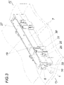
- eine Konstruktionsvariante der Erfindung in perspektivischer Ansicht mit zwei übereinander angeordneten schiefsymmetrischen Schutzgehäusen,
- Fig. 4
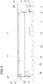
- die Vorrichtung aus
Fig. 3 im teilgeschnittenen Längsschnitt mit einer Halteschiene und - Fig. 5
- Vorrichtungen aus
Fig. 3 und4 in Draufsicht in verschiedenen Einbausituationen und - Fig. 5
- eine Vorrichtunge aus
Fig. 5 im Längsschnitt in einer weiteren Einbausituation.
- 1
- a perspective view of the device according to the invention and
- 2
- a section along the line II-II of the device according to the invention cast into a panel heating prefabricated part.
- 3
- a design variant of the invention in a perspective view with two obliquely symmetrical protective housings arranged one above the other,
- 4
- the device off
3 in a partially sectioned longitudinal section with a retaining rail and - figure 5
- devices off
3 and4 in top view in different installation situations and - figure 5
- a device
figure 5 in longitudinal section in another installation situation.
Eine Vorrichtung zum Festlegen von Flächenheizungsrohren 1 an einer Schalung weist, wie
Eine besonders kompakte Vorrichtung ergibt sich, wenn der Durchbruch 10 im Bereich einer Rohraufnahme 5 angeordnet ist, da dadurch ein in der Rohraufnahme 5 angeordnetes Flächenheizungsrohr 1 direkt in das Schutzgehäuse 7 eingeführt werden kann. Eine solche kompakte Anordnung ergibt sich beispielsweise, wenn die Durchbruchsachse parallel zur Zapfenachse ist, wobei deren Achsabstand dem Abstand benachbarter Rohraufnahmeachsen entspricht.A particularly compact device results when the
Der Zapfen 6 kann endabschnittseitig einen Zapfenkopf 13 mir vergrößertem Querschnitt bzw. Durchmesser aufweisen, wodurch das Schutzgehäuse 7 bzw. die Halteschiene 2 in Zapfenlängsrichtung gegenseitig gesichert sind.The
Der Schutzgehäuseboden 14 kann von mehreren Austrittslöchern 15 durchsetzt sein, wodurch etwaiges aus den Flächenheizungsrohrenden 8 austretendes Wärmeträgerfluid aus dem Schutzgehäuse 7 austreten kann und somit eine Leckage sichtbar wird.The
Damit auch der Schutzgehäuseboden 18 beim Ausgießen von der Betonvergussmasse 9 umschlossen wird, kann dieser Vorsprünge 19 aufweisen, sodass sich ein Spalt, in den die noch nicht ausgehärtete Betonvergussmasse 9 eindringen kann, zwischen Schutzgehäuseboden 18 und Schalungsboden 16 ergibt.So that the
Aus der
Wie in
Das Schutzgehäuse 7 gem. Fig. 3ff ist mit Wandungen und Schutzgehäuseboden 14 derart schiefsymmetrisch ausgeführt, dass mit voneinander abgewandten Schutzgehäuseböden 14 schiefsymmetrisch übereinander angeordnete Schutzgehäuse 7 mit Verbindungselementen, nämlich hinterschnittene Nuten 25 und in diese eingreifende Laschen 26, zu einem vergrößerten Schutzgehäuse doppelter Höhe verbindbar sind. Der Schutzgehäuseboden 14 kann zumindest teilweise über eine Sollbruchstelle 27 in das Schutzgehäuse 7 eingebunden sein. Der Schutzgehäuseboden 14 kann wiederum von mehreren in diesen Fig. nicht dargestellten Austrittslöchern 15 durchsetzt sein.The
Auch der Durchbruch 19 kann mit einem über eine Sollbruchstelle 27 in das Schutzgehäuse 7 eingebundenen Verschluss 28 ausgestattet sein, ebenso wie der Zapfen 6 über eine Sollbruchstelle 27 in das Schutzgehäuse 7 eingebunden sein kann. Die ist insbesondere von Vorteil, wenn zwei oder mehrere Schutzgehäuse 7 zu größeren Baueinheiten verbunden werden sollen.The
Der Zapfen 6 kann wenigstens mit einem radial vom Zapfen 6 abragenden, zusammen mit der Rohraufnahme 5 eine Verdrehsicherung für das Schutzgehäuse 7 bildenden, Ansatz 29 aufweisen.The
Wenigstens zwei Schutzgehäuse 7 können quer zur Schienenlängsrichtung aneinander anschließend angeordnet sein und dass die aneinander anschließenden Schutzgehäuse (7) mit Längskupplungselementen, einer Schwalbenschwanzführung 30 und einer Schwalbenschwanzfeder 31, zu einem verlängerten Schutzgehäuse verbindbar sein.At least two
Gleichermaßen können wenigstens zwei Schutzgehäuse 7 parallel zur Schienenlängsrichtung aneinander anschließend angeordnet sein, wobei die aneinander anschließenden Schutzgehäuse 7 mit Querkupplungselementen, einer Schwalbenschwanzführung 30 und einer Schwalbenschwanzfeder 31, zu einem verbreiterten Schutzgehäuse verbindbar sind. Die Schwalbenschwanzfedern 31 können Längsbohrungen 32 aufweisen, durch die Nägel zur Befestigung des Schutzgehäuses 7 an der Schalung eingetrieben werden können. Durch die integrierte, dünne, einen eingezogenen Rand der jeweiligen Längsbohrungen 32 bildende Auflagefläche 33 für einen Nagelkopf, können etwaige Nägel mit der Schalung von der fertigen Betondecke abgenommenen werden.Equally, at least two
Um Rohre bzw. Schutzschläuche für Rohre stabil in dem Schutzgehäuse 7 festlegen zu können den Durchbrüchen entsprechende Rückhaltekrallen 34 zugeordnet sein, die ein Ausziehen eines Rohrs bzw. Schutzschlauchs aus dem Schutzgehäuse 7 unterbinden.In order to be able to stably fix pipes or protective hoses for pipes in the
Claims (15)
Applications Claiming Priority (1)
| Application Number | Priority Date | Filing Date | Title |
|---|---|---|---|
| ATGM50114/2021U AT17537U1 (en) | 2021-06-01 | 2021-06-01 | Device for fixing surface heating pipes |
Publications (1)
| Publication Number | Publication Date |
|---|---|
| EP4098948A1 true EP4098948A1 (en) | 2022-12-07 |
Family
ID=82156802
Family Applications (1)
| Application Number | Title | Priority Date | Filing Date |
|---|---|---|---|
| EP22176451.7A Pending EP4098948A1 (en) | 2021-06-01 | 2022-05-31 | Device for fixing area heating pipes |
Country Status (2)
| Country | Link |
|---|---|
| EP (1) | EP4098948A1 (en) |
| AT (1) | AT17537U1 (en) |
Citations (3)
| Publication number | Priority date | Publication date | Assignee | Title |
|---|---|---|---|---|
| EP1207354A2 (en) * | 2000-11-17 | 2002-05-22 | Josef Steiner | Mounting strip, heating or cooling register also a flat building part from hardenable material |
| FR2976009A1 (en) * | 2011-05-30 | 2012-12-07 | Ain corp | EXTRACTIBLE BOX FOR THE INCORPORATION OF PIPES IN A CONCRETE SLAB AND METHOD OF IMPLEMENTING THE SAME |
| EP2679923B1 (en) | 2012-06-27 | 2020-04-22 | KE KELIT Kunststoffwerk Gesellschaft m.b.H. | Method for air conditioning a room |
Family Cites Families (5)
| Publication number | Priority date | Publication date | Assignee | Title |
|---|---|---|---|---|
| DE7204606U (en) * | 1972-02-08 | 1972-06-15 | Braunwarth L | PREFABRICATED FORMWORK FOR THE PRODUCTION OF RECESSES IN CONCRETE SLABS AND WALLS |
| JPS54144972U (en) * | 1978-03-31 | 1979-10-08 | ||
| JP3000692U (en) * | 1994-02-02 | 1994-08-09 | 稲留工業株式会社 | Hot water heating mat |
| DE202011108342U1 (en) * | 2011-11-28 | 2012-02-15 | Oventrop Gmbh & Co. Kg | Mounting box for distributorless underfloor heating |
| IT201800003450A1 (en) * | 2018-03-12 | 2019-09-12 | Enolgas Bonomi S P A | DISTRIBUTION MANIFOLD |
-
2021
- 2021-06-01 AT ATGM50114/2021U patent/AT17537U1/en unknown
-
2022
- 2022-05-31 EP EP22176451.7A patent/EP4098948A1/en active Pending
Patent Citations (3)
| Publication number | Priority date | Publication date | Assignee | Title |
|---|---|---|---|---|
| EP1207354A2 (en) * | 2000-11-17 | 2002-05-22 | Josef Steiner | Mounting strip, heating or cooling register also a flat building part from hardenable material |
| FR2976009A1 (en) * | 2011-05-30 | 2012-12-07 | Ain corp | EXTRACTIBLE BOX FOR THE INCORPORATION OF PIPES IN A CONCRETE SLAB AND METHOD OF IMPLEMENTING THE SAME |
| EP2679923B1 (en) | 2012-06-27 | 2020-04-22 | KE KELIT Kunststoffwerk Gesellschaft m.b.H. | Method for air conditioning a room |
Also Published As
| Publication number | Publication date |
|---|---|
| AT17537U1 (en) | 2022-07-15 |
Similar Documents
| Publication | Publication Date | Title |
|---|---|---|
| DE202006006361U1 (en) | Feed-through for passing pipes through walls comprises tubular housing with flange at one end with swellable packing above it, stud and tube on either side of housing forming snap-fittings allowing other feed-throughs to be connected | |
| EP2978911B1 (en) | Device, assembly and method for fixing a scaffold to a façade and method for manufacturing the device | |
| DE1997149U (en) | DEVICE FOR PREVENTING VIBRATIONS IN A BUNCH OR IN A LAY OF PARALLEL PIPES | |
| EP4093930B1 (en) | Frame formwork element | |
| EP3514297A1 (en) | Profile rail with plug for attachment to a formwork | |
| EP0193494B1 (en) | Joining and stress-spreading element for concrete building parts | |
| EP4098948A1 (en) | Device for fixing area heating pipes | |
| CH712235B1 (en) | Installation box. | |
| DE102013216838B3 (en) | Formwork arrangement for manufacturing ring joist or peripheral tie beam of concreted wall parts on masonry in buildings, has holder element with module regions introduced into seam cavity in side piece of connectors over opening | |
| DE2745278A1 (en) | INSERT SOCKET FOR ELECTRICAL INSTALLATIONS | |
| DE19528685C2 (en) | Device for producing installation breakthroughs | |
| EP3584898A1 (en) | Installation socket | |
| EP1253386A2 (en) | Assembling jig | |
| DE3545917A1 (en) | Grate for closing openings in the ground, gutters and the like, and process for producing a grate | |
| DE3832399A1 (en) | Pipe-retaining means and process for mounting a pipe by means of a pipe-retaining means | |
| DE102017120676A1 (en) | Ceiling Panel System | |
| EP0962710B1 (en) | Pipe support device for laying sanitary, heating pipes or the like in concrete floors | |
| DE10217980B3 (en) | Device for positioning at least one casing, which is part of a house entry for introducing media lines into a building from below, and which encloses a number of lines | |
| DE3429642C1 (en) | Method of shutting off moisture rising in masonry | |
| DE102004045136A1 (en) | Electrical box assembling method, involves holding box in opening of wall using assembly-auxiliary unit, which is detachably connected with box and attached at wall, and attaching box at and/or in wall using self-hardening material | |
| EP3012931B1 (en) | Holder for electrical installations | |
| DD245538A1 (en) | INSTALLATION BOX FOR INSERTING IN SAVINGS OF COMPONENTS | |
| DE102018133622A1 (en) | Holding element for an installation housing | |
| DE19925485C1 (en) | Support bracket for heating radiator mounting rail has wall-mounted grid arm and releasable horizontal arm fitted into socket provided by perpendicular projection of grid arm | |
| DE102010064571B3 (en) | Fire protection sleeve |
Legal Events
| Date | Code | Title | Description |
|---|---|---|---|
| PUAI | Public reference made under article 153(3) epc to a published international application that has entered the european phase |
Free format text: ORIGINAL CODE: 0009012 |
|
| STAA | Information on the status of an ep patent application or granted ep patent |
Free format text: STATUS: THE APPLICATION HAS BEEN PUBLISHED |
|
| AK | Designated contracting states |
Kind code of ref document: A1 Designated state(s): AL AT BE BG CH CY CZ DE DK EE ES FI FR GB GR HR HU IE IS IT LI LT LU LV MC MK MT NL NO PL PT RO RS SE SI SK SM TR |
|
| STAA | Information on the status of an ep patent application or granted ep patent |
Free format text: STATUS: REQUEST FOR EXAMINATION WAS MADE |
|
| 17P | Request for examination filed |
Effective date: 20230414 |
|
| RBV | Designated contracting states (corrected) |
Designated state(s): AL AT BE BG CH CY CZ DE DK EE ES FI FR GB GR HR HU IE IS IT LI LT LU LV MC MK MT NL NO PL PT RO RS SE SI SK SM TR |
|
| GRAP | Despatch of communication of intention to grant a patent |
Free format text: ORIGINAL CODE: EPIDOSNIGR1 |
|
| STAA | Information on the status of an ep patent application or granted ep patent |
Free format text: STATUS: GRANT OF PATENT IS INTENDED |
|
| RIC1 | Information provided on ipc code assigned before grant |
Ipc: E04G 15/06 20060101ALI20240215BHEP Ipc: F24D 19/00 20060101ALI20240215BHEP Ipc: F24D 3/14 20060101AFI20240215BHEP |
|
| INTG | Intention to grant announced |
Effective date: 20240306 |
|
| GRAS | Grant fee paid |
Free format text: ORIGINAL CODE: EPIDOSNIGR3 |
|
| GRAA | (expected) grant |
Free format text: ORIGINAL CODE: 0009210 |
|
| STAA | Information on the status of an ep patent application or granted ep patent |
Free format text: STATUS: THE PATENT HAS BEEN GRANTED |