EP4098539A1 - Schiff zum transport oder zur verwendung eines kalten fluids - Google Patents
Schiff zum transport oder zur verwendung eines kalten fluids Download PDFInfo
- Publication number
- EP4098539A1 EP4098539A1 EP22173908.9A EP22173908A EP4098539A1 EP 4098539 A1 EP4098539 A1 EP 4098539A1 EP 22173908 A EP22173908 A EP 22173908A EP 4098539 A1 EP4098539 A1 EP 4098539A1
- Authority
- EP
- European Patent Office
- Prior art keywords
- cofferdam
- internal space
- threshold value
- transverse
- gas
- Prior art date
- Legal status (The legal status is an assumption and is not a legal conclusion. Google has not performed a legal analysis and makes no representation as to the accuracy of the status listed.)
- Granted
Links
Images




Classifications
-
- B—PERFORMING OPERATIONS; TRANSPORTING
- B63—SHIPS OR OTHER WATERBORNE VESSELS; RELATED EQUIPMENT
- B63B—SHIPS OR OTHER WATERBORNE VESSELS; EQUIPMENT FOR SHIPPING
- B63B25/00—Load-accommodating arrangements, e.g. stowing, trimming; Vessels characterised thereby
- B63B25/02—Load-accommodating arrangements, e.g. stowing, trimming; Vessels characterised thereby for bulk goods
- B63B25/08—Load-accommodating arrangements, e.g. stowing, trimming; Vessels characterised thereby for bulk goods fluid
- B63B25/12—Load-accommodating arrangements, e.g. stowing, trimming; Vessels characterised thereby for bulk goods fluid closed
- B63B25/16—Load-accommodating arrangements, e.g. stowing, trimming; Vessels characterised thereby for bulk goods fluid closed heat-insulated
-
- B—PERFORMING OPERATIONS; TRANSPORTING
- B63—SHIPS OR OTHER WATERBORNE VESSELS; RELATED EQUIPMENT
- B63B—SHIPS OR OTHER WATERBORNE VESSELS; EQUIPMENT FOR SHIPPING
- B63B25/00—Load-accommodating arrangements, e.g. stowing, trimming; Vessels characterised thereby
- B63B25/02—Load-accommodating arrangements, e.g. stowing, trimming; Vessels characterised thereby for bulk goods
- B63B25/08—Load-accommodating arrangements, e.g. stowing, trimming; Vessels characterised thereby for bulk goods fluid
- B63B25/12—Load-accommodating arrangements, e.g. stowing, trimming; Vessels characterised thereby for bulk goods fluid closed
-
- B—PERFORMING OPERATIONS; TRANSPORTING
- B63—SHIPS OR OTHER WATERBORNE VESSELS; RELATED EQUIPMENT
- B63B—SHIPS OR OTHER WATERBORNE VESSELS; EQUIPMENT FOR SHIPPING
- B63B11/00—Interior subdivision of hulls
-
- B—PERFORMING OPERATIONS; TRANSPORTING
- B63—SHIPS OR OTHER WATERBORNE VESSELS; RELATED EQUIPMENT
- B63B—SHIPS OR OTHER WATERBORNE VESSELS; EQUIPMENT FOR SHIPPING
- B63B11/00—Interior subdivision of hulls
- B63B11/04—Constructional features of bunkers, e.g. structural fuel tanks, or ballast tanks, e.g. with elastic walls
-
- B—PERFORMING OPERATIONS; TRANSPORTING
- B63—SHIPS OR OTHER WATERBORNE VESSELS; RELATED EQUIPMENT
- B63B—SHIPS OR OTHER WATERBORNE VESSELS; EQUIPMENT FOR SHIPPING
- B63B27/00—Arrangement of ship-based loading or unloading equipment for cargo or passengers
- B63B27/24—Arrangement of ship-based loading or unloading equipment for cargo or passengers of pipe-lines
-
- B—PERFORMING OPERATIONS; TRANSPORTING
- B63—SHIPS OR OTHER WATERBORNE VESSELS; RELATED EQUIPMENT
- B63B—SHIPS OR OTHER WATERBORNE VESSELS; EQUIPMENT FOR SHIPPING
- B63B27/00—Arrangement of ship-based loading or unloading equipment for cargo or passengers
- B63B27/30—Arrangement of ship-based loading or unloading equipment for transfer at sea between ships or between ships and off-shore structures
- B63B27/34—Arrangement of ship-based loading or unloading equipment for transfer at sea between ships or between ships and off-shore structures using pipe-lines
-
- B—PERFORMING OPERATIONS; TRANSPORTING
- B63—SHIPS OR OTHER WATERBORNE VESSELS; RELATED EQUIPMENT
- B63J—AUXILIARIES ON VESSELS
- B63J2/00—Arrangements of ventilation, heating, cooling, or air-conditioning
- B63J2/02—Ventilation; Air-conditioning
-
- B—PERFORMING OPERATIONS; TRANSPORTING
- B63—SHIPS OR OTHER WATERBORNE VESSELS; RELATED EQUIPMENT
- B63J—AUXILIARIES ON VESSELS
- B63J2/00—Arrangements of ventilation, heating, cooling, or air-conditioning
- B63J2/12—Heating; Cooling
-
- B—PERFORMING OPERATIONS; TRANSPORTING
- B63—SHIPS OR OTHER WATERBORNE VESSELS; RELATED EQUIPMENT
- B63J—AUXILIARIES ON VESSELS
- B63J2/00—Arrangements of ventilation, heating, cooling, or air-conditioning
- B63J2/12—Heating; Cooling
- B63J2/14—Heating; Cooling of liquid-freight-carrying tanks
-
- F—MECHANICAL ENGINEERING; LIGHTING; HEATING; WEAPONS; BLASTING
- F17—STORING OR DISTRIBUTING GASES OR LIQUIDS
- F17C—VESSELS FOR CONTAINING OR STORING COMPRESSED, LIQUEFIED OR SOLIDIFIED GASES; FIXED-CAPACITY GAS-HOLDERS; FILLING VESSELS WITH, OR DISCHARGING FROM VESSELS, COMPRESSED, LIQUEFIED, OR SOLIDIFIED GASES
- F17C13/00—Details of vessels or of the filling or discharging of vessels
- F17C13/001—Thermal insulation specially adapted for cryogenic vessels
-
- F—MECHANICAL ENGINEERING; LIGHTING; HEATING; WEAPONS; BLASTING
- F17—STORING OR DISTRIBUTING GASES OR LIQUIDS
- F17C—VESSELS FOR CONTAINING OR STORING COMPRESSED, LIQUEFIED OR SOLIDIFIED GASES; FIXED-CAPACITY GAS-HOLDERS; FILLING VESSELS WITH, OR DISCHARGING FROM VESSELS, COMPRESSED, LIQUEFIED, OR SOLIDIFIED GASES
- F17C2201/00—Vessel construction, in particular geometry, arrangement or size
- F17C2201/01—Shape
- F17C2201/0147—Shape complex
- F17C2201/0157—Polygonal
-
- F—MECHANICAL ENGINEERING; LIGHTING; HEATING; WEAPONS; BLASTING
- F17—STORING OR DISTRIBUTING GASES OR LIQUIDS
- F17C—VESSELS FOR CONTAINING OR STORING COMPRESSED, LIQUEFIED OR SOLIDIFIED GASES; FIXED-CAPACITY GAS-HOLDERS; FILLING VESSELS WITH, OR DISCHARGING FROM VESSELS, COMPRESSED, LIQUEFIED, OR SOLIDIFIED GASES
- F17C2201/00—Vessel construction, in particular geometry, arrangement or size
- F17C2201/05—Size
- F17C2201/052—Size large (>1000 m3)
-
- F—MECHANICAL ENGINEERING; LIGHTING; HEATING; WEAPONS; BLASTING
- F17—STORING OR DISTRIBUTING GASES OR LIQUIDS
- F17C—VESSELS FOR CONTAINING OR STORING COMPRESSED, LIQUEFIED OR SOLIDIFIED GASES; FIXED-CAPACITY GAS-HOLDERS; FILLING VESSELS WITH, OR DISCHARGING FROM VESSELS, COMPRESSED, LIQUEFIED, OR SOLIDIFIED GASES
- F17C2203/00—Vessel construction, in particular walls or details thereof
- F17C2203/03—Thermal insulations
- F17C2203/0304—Thermal insulations by solid means
- F17C2203/0329—Foam
- F17C2203/0333—Polyurethane
-
- F—MECHANICAL ENGINEERING; LIGHTING; HEATING; WEAPONS; BLASTING
- F17—STORING OR DISTRIBUTING GASES OR LIQUIDS
- F17C—VESSELS FOR CONTAINING OR STORING COMPRESSED, LIQUEFIED OR SOLIDIFIED GASES; FIXED-CAPACITY GAS-HOLDERS; FILLING VESSELS WITH, OR DISCHARGING FROM VESSELS, COMPRESSED, LIQUEFIED, OR SOLIDIFIED GASES
- F17C2203/00—Vessel construction, in particular walls or details thereof
- F17C2203/03—Thermal insulations
- F17C2203/0304—Thermal insulations by solid means
- F17C2203/0345—Fibres
- F17C2203/035—Glass wool
-
- F—MECHANICAL ENGINEERING; LIGHTING; HEATING; WEAPONS; BLASTING
- F17—STORING OR DISTRIBUTING GASES OR LIQUIDS
- F17C—VESSELS FOR CONTAINING OR STORING COMPRESSED, LIQUEFIED OR SOLIDIFIED GASES; FIXED-CAPACITY GAS-HOLDERS; FILLING VESSELS WITH, OR DISCHARGING FROM VESSELS, COMPRESSED, LIQUEFIED, OR SOLIDIFIED GASES
- F17C2203/00—Vessel construction, in particular walls or details thereof
- F17C2203/03—Thermal insulations
- F17C2203/0375—Thermal insulations by gas
- F17C2203/0383—Air
-
- F—MECHANICAL ENGINEERING; LIGHTING; HEATING; WEAPONS; BLASTING
- F17—STORING OR DISTRIBUTING GASES OR LIQUIDS
- F17C—VESSELS FOR CONTAINING OR STORING COMPRESSED, LIQUEFIED OR SOLIDIFIED GASES; FIXED-CAPACITY GAS-HOLDERS; FILLING VESSELS WITH, OR DISCHARGING FROM VESSELS, COMPRESSED, LIQUEFIED, OR SOLIDIFIED GASES
- F17C2221/00—Handled fluid, in particular type of fluid
- F17C2221/03—Mixtures
- F17C2221/032—Hydrocarbons
- F17C2221/033—Methane, e.g. natural gas, CNG, LNG, GNL, GNC, PLNG
-
- F—MECHANICAL ENGINEERING; LIGHTING; HEATING; WEAPONS; BLASTING
- F17—STORING OR DISTRIBUTING GASES OR LIQUIDS
- F17C—VESSELS FOR CONTAINING OR STORING COMPRESSED, LIQUEFIED OR SOLIDIFIED GASES; FIXED-CAPACITY GAS-HOLDERS; FILLING VESSELS WITH, OR DISCHARGING FROM VESSELS, COMPRESSED, LIQUEFIED, OR SOLIDIFIED GASES
- F17C2221/00—Handled fluid, in particular type of fluid
- F17C2221/03—Mixtures
- F17C2221/032—Hydrocarbons
- F17C2221/035—Propane butane, e.g. LPG, GPL
-
- F—MECHANICAL ENGINEERING; LIGHTING; HEATING; WEAPONS; BLASTING
- F17—STORING OR DISTRIBUTING GASES OR LIQUIDS
- F17C—VESSELS FOR CONTAINING OR STORING COMPRESSED, LIQUEFIED OR SOLIDIFIED GASES; FIXED-CAPACITY GAS-HOLDERS; FILLING VESSELS WITH, OR DISCHARGING FROM VESSELS, COMPRESSED, LIQUEFIED, OR SOLIDIFIED GASES
- F17C2223/00—Handled fluid before transfer, i.e. state of fluid when stored in the vessel or before transfer from the vessel
- F17C2223/01—Handled fluid before transfer, i.e. state of fluid when stored in the vessel or before transfer from the vessel characterised by the phase
- F17C2223/0146—Two-phase
- F17C2223/0153—Liquefied gas, e.g. LPG, GPL
-
- F—MECHANICAL ENGINEERING; LIGHTING; HEATING; WEAPONS; BLASTING
- F17—STORING OR DISTRIBUTING GASES OR LIQUIDS
- F17C—VESSELS FOR CONTAINING OR STORING COMPRESSED, LIQUEFIED OR SOLIDIFIED GASES; FIXED-CAPACITY GAS-HOLDERS; FILLING VESSELS WITH, OR DISCHARGING FROM VESSELS, COMPRESSED, LIQUEFIED, OR SOLIDIFIED GASES
- F17C2223/00—Handled fluid before transfer, i.e. state of fluid when stored in the vessel or before transfer from the vessel
- F17C2223/01—Handled fluid before transfer, i.e. state of fluid when stored in the vessel or before transfer from the vessel characterised by the phase
- F17C2223/0146—Two-phase
- F17C2223/0153—Liquefied gas, e.g. LPG, GPL
- F17C2223/0161—Liquefied gas, e.g. LPG, GPL cryogenic, e.g. LNG, GNL, PLNG
-
- F—MECHANICAL ENGINEERING; LIGHTING; HEATING; WEAPONS; BLASTING
- F17—STORING OR DISTRIBUTING GASES OR LIQUIDS
- F17C—VESSELS FOR CONTAINING OR STORING COMPRESSED, LIQUEFIED OR SOLIDIFIED GASES; FIXED-CAPACITY GAS-HOLDERS; FILLING VESSELS WITH, OR DISCHARGING FROM VESSELS, COMPRESSED, LIQUEFIED, OR SOLIDIFIED GASES
- F17C2223/00—Handled fluid before transfer, i.e. state of fluid when stored in the vessel or before transfer from the vessel
- F17C2223/03—Handled fluid before transfer, i.e. state of fluid when stored in the vessel or before transfer from the vessel characterised by the pressure level
- F17C2223/033—Small pressure, e.g. for liquefied gas
-
- F—MECHANICAL ENGINEERING; LIGHTING; HEATING; WEAPONS; BLASTING
- F17—STORING OR DISTRIBUTING GASES OR LIQUIDS
- F17C—VESSELS FOR CONTAINING OR STORING COMPRESSED, LIQUEFIED OR SOLIDIFIED GASES; FIXED-CAPACITY GAS-HOLDERS; FILLING VESSELS WITH, OR DISCHARGING FROM VESSELS, COMPRESSED, LIQUEFIED, OR SOLIDIFIED GASES
- F17C2227/00—Transfer of fluids, i.e. method or means for transferring the fluid; Heat exchange with the fluid
- F17C2227/01—Propulsion of the fluid
- F17C2227/0128—Propulsion of the fluid with pumps or compressors
- F17C2227/0135—Pumps
-
- F—MECHANICAL ENGINEERING; LIGHTING; HEATING; WEAPONS; BLASTING
- F17—STORING OR DISTRIBUTING GASES OR LIQUIDS
- F17C—VESSELS FOR CONTAINING OR STORING COMPRESSED, LIQUEFIED OR SOLIDIFIED GASES; FIXED-CAPACITY GAS-HOLDERS; FILLING VESSELS WITH, OR DISCHARGING FROM VESSELS, COMPRESSED, LIQUEFIED, OR SOLIDIFIED GASES
- F17C2260/00—Purposes of gas storage and gas handling
- F17C2260/03—Dealing with losses
- F17C2260/031—Dealing with losses due to heat transfer
- F17C2260/032—Avoiding freezing or defrosting
-
- F—MECHANICAL ENGINEERING; LIGHTING; HEATING; WEAPONS; BLASTING
- F17—STORING OR DISTRIBUTING GASES OR LIQUIDS
- F17C—VESSELS FOR CONTAINING OR STORING COMPRESSED, LIQUEFIED OR SOLIDIFIED GASES; FIXED-CAPACITY GAS-HOLDERS; FILLING VESSELS WITH, OR DISCHARGING FROM VESSELS, COMPRESSED, LIQUEFIED, OR SOLIDIFIED GASES
- F17C2265/00—Effects achieved by gas storage or gas handling
- F17C2265/03—Treating the boil-off
- F17C2265/032—Treating the boil-off by recovery
- F17C2265/033—Treating the boil-off by recovery with cooling
- F17C2265/034—Treating the boil-off by recovery with cooling with condensing the gas phase
-
- F—MECHANICAL ENGINEERING; LIGHTING; HEATING; WEAPONS; BLASTING
- F17—STORING OR DISTRIBUTING GASES OR LIQUIDS
- F17C—VESSELS FOR CONTAINING OR STORING COMPRESSED, LIQUEFIED OR SOLIDIFIED GASES; FIXED-CAPACITY GAS-HOLDERS; FILLING VESSELS WITH, OR DISCHARGING FROM VESSELS, COMPRESSED, LIQUEFIED, OR SOLIDIFIED GASES
- F17C2270/00—Applications
- F17C2270/01—Applications for fluid transport or storage
- F17C2270/0102—Applications for fluid transport or storage on or in the water
- F17C2270/0105—Ships
-
- F—MECHANICAL ENGINEERING; LIGHTING; HEATING; WEAPONS; BLASTING
- F17—STORING OR DISTRIBUTING GASES OR LIQUIDS
- F17C—VESSELS FOR CONTAINING OR STORING COMPRESSED, LIQUEFIED OR SOLIDIFIED GASES; FIXED-CAPACITY GAS-HOLDERS; FILLING VESSELS WITH, OR DISCHARGING FROM VESSELS, COMPRESSED, LIQUEFIED, OR SOLIDIFIED GASES
- F17C2270/00—Applications
- F17C2270/01—Applications for fluid transport or storage
- F17C2270/0102—Applications for fluid transport or storage on or in the water
- F17C2270/0105—Ships
- F17C2270/0107—Wall panels
Definitions
- the invention relates to the field of vessels for transporting a cold fluid.
- the invention relates to the field of ships comprising watertight and thermally insulating tanks for the transport of a liquefied gas, in particular LNG and to the ship propelled by liquefied gas, for example propelled by LNG.
- Liquefied natural gas is stored in airtight and thermally insulating tanks, in a two-phase liquid/vapor equilibrium state, at cryogenic temperatures, in particular Liquefied Natural Gas (LNG) is at around -162°C at atmospheric pressure.
- LNG Liquefied Natural Gas
- the tank can be made using different techniques, in particular in the form of an integrated membrane cargo tank or a self-supporting tank.
- the thermal insulation barriers of the liquefied natural gas storage tanks and the adjacent compartments are the site of a thermal flow tending to heat the contents of the tanks, which results in evaporation of the liquefied natural gas.
- the gas resulting from natural evaporation is generally used to supply a gas-consuming organ, in order to recover it.
- the evaporated gas is used to supply the powertrain to propel the ship.
- it makes it possible to recover the gas resulting from natural evaporation in the liquefied gas transport tanks, it does not make it possible to reduce its quantity.
- Boil-Off Rate the rate of evaporation, commonly called “ Boil-Off Rate ” (BOR) of the liquid contained in the tank is a major problem leading in particular to a loss of part of the cargo.
- liquefied natural gas it is also common for liquefied natural gas to be on board to constitute the, or at least one of, the fuel ensuring the propulsion of ships of any type, for example LNG carriers or LNG carriers, oil tankers, but also container ships.
- LNG carriers or LNG carriers for example LNG carriers or LNG carriers, oil tankers, but also container ships.
- LNG Fueled Ship or LFS.
- at least one LNG tank it is common for at least one LNG tank to be located close to a heat source, for example an engine room.
- An idea underlying the invention is to provide a vessel whose temperature can be lowered in the internal space of a transverse cofferdam in order to reduce the heat flows between this internal space and an adjacent vessel and therefore the rate of evaporation in the tank containing cold liquid.
- One objective is, for example, to reduce the BOR by 5% or 6%.
- One idea underlying the invention is to reduce the heat fluxes between hollow spaces of the ship adjacent to the LNG storage tanks and the external environment, in particular ballast water and atmospheric air, for example reducing the fluxes thermal passing through the periphery of the cofferdams.
- Another idea at the basis of the invention is to reduce the heat flows in the cofferdams located between a hot source and an LNG tank in order to preserve said hot source and said LNG tank from changes in temperature.
- Another idea underlying the invention is to manage the gaseous atmosphere in the cofferdams of a ship.
- Another idea underlying the invention is to reduce the temperature in the cofferdams in order to reduce the BOR in the tanks storing the LNG.
- Another idea underlying the invention is to obtain an equilibrium temperature in the cofferdams, for example -15 degrees Celsius (°C) or -25°C, while preserving its integrity.
- the invention thus proposes to integrate a gas management installation to manage a gaseous atmosphere in a hollow space of the ship such as the cofferdams to solve the technical problems presented.
- fluid includes liquids and gases.
- cold or “cryogenic” is defined as being a low temperature, for example negative temperatures (in °C) such as -50°C or -162°C.
- cofferdam is defined as being a hollow separation space in a ship adjacent to at least one tank, it can also be called “cofferdam” or “dry mesh”.
- valve refers to a valve or valve.
- the pressure of the gaseous atmosphere in the internal space of the transverse cofferdam is regulated so as to remain higher than the ambient pressure, so that a spontaneous entry of ambient air and humidity is prevented.
- These characteristics make it possible in particular to prevent deterioration due to corrosion of the various elements located in the internal space of the transverse cofferdam.
- the gas management installation makes it possible to maintain the relative pressure in a positive range comprised between the second threshold value and the first threshold value despite the variations in temperature in the internal space and the variations in the ambient pressure. Thanks to the first threshold value, it is possible to limit the pressure which will be exerted on the pair of transverse partitions and the upper wall of the transverse cofferdam.
- such a ship may comprise one or more of the following characteristics.
- the pressure regulator is further configured to: closing the inlet valve when the pressure in the internal space becomes greater than a third threshold value between the second threshold value and the first threshold value.
- the operation of the inlet valve is optimized and also makes it possible to avoid too many openings or closings of the inlet valve which could cause premature wear of the equipment.
- a difference between the third threshold value and the second threshold value is less than 2 kPa (kilopascal) (20 mbarg).
- a difference between the third threshold value and the second threshold value is between 0.5 kPa and 1.5 kPa, for example a difference of 1 kPa.
- the pressure regulator is additionally connected to the evacuation valve, the pressure regulator is additionally configured for: open the evacuation valve when the pressure in the internal space becomes higher than the first threshold value.
- the pressure regulator is further configured to: closing the evacuation valve when the pressure in the internal space becomes lower than a fourth threshold value comprised between the first threshold value and the second threshold value.
- the operation of the evacuation valve is optimized and also makes it possible to avoid too many openings or closings of the evacuation valve which could lead to premature wear of the equipment.
- a difference between the fourth threshold value and the first threshold value is less than 2 kPa (20 mbarg).
- a difference between the fourth threshold value and the first threshold value is between 0.5 kPa and 1.5 kPa, for example a difference of 1 kPa.
- the evacuation valve is a mechanical opening and closing evacuation valve configured to: open when a relative pressure in the internal space becomes greater than the first threshold value.
- the evacuation valve is configured to: closing when the pressure in the internal space of the transverse cofferdam becomes lower than a fourth threshold value between the first threshold value and the second threshold value.
- the evacuation valve is chosen from among a ball valve, a needle valve, a butterfly valve, a guillotine valve, a flap valve, a check valve, a piston valve, a diaphragm valve, high speed vacuum pressure relief valve, safety valve, spring loaded safety valve or poppet.
- the second threshold value is between 1 kPa (10 mbarg) and 10 kPa (100 mbarg), preferably between 2 kPa (20 mbarg) and 5 kPa (50 mbarg).
- the second threshold value is 2 kPa or 5 kPa.
- the first threshold value is between 12 kPa (120 mbarg) and 18 kPa (180 mbarg), preferably between 13 kPa (130 mbarg) and 15 kPa (150 mbarg).
- the first threshold value is 14 kPa (140 mbarg).
- the gas management installation further comprises a gas sampling valve, the gas sampling valve being mounted on the gas evacuation conduit, upstream of the evacuation valve in order to allow a sample of a volume of gas coming from the internal space of the transverse cofferdam.
- the pair of transverse partitions is manufactured in a grade of steel chosen from grade D, grade E, grade DH and/or grade EH.
- grade D grade E
- grade DH grade DH
- grade EH grade D and/or Grade E steel grade is preferred.
- the pair of transverse partitions has a thickness greater than or equal to 10 mm, for example a thickness of between 10 mm and 50 mm, preferably a thickness of between 15 mm and 20 mm.
- the longitudinal walls of the cofferdam are made of a grade of steel chosen from grade D, grade E, grade DH and/or grade EH.
- a Grade D and/or Grade E steel grade is preferred.
- the longitudinal walls of the cofferdam have a thickness greater than or equal to 10 mm, for example a thickness of between 10 mm and 50 mm, preferably a thickness of between 15 mm and 20 mm.
- the transverse cofferdam comprises a thermal insulator.
- the thermal fluxes are reduced between the sealed and thermally insulating tank and the heat source(s) located close to said tank.
- the thermal insulation is located on an outer surface of the cofferdam. According to one embodiment, the thermal insulation is located on an outer surface of the pair of transverse partitions.
- the thermal insulation is located in the internal space of the transverse cofferdam, the thermal insulation being preferably fixed on longitudinal walls of the transverse cofferdam including the upper wall and a portion of the internal shell.
- the gas management installation allows the thermal insulation to be maintained in a dry state.
- the thermal insulation is not damaged by humidity or waterlogged.
- the thermal properties of the thermal insulation are therefore optimally preserved.
- the thermal insulation when the transverse cofferdam is adjacent to a single tank, the thermal insulation also covers the partition of the pair of partitions which is furthest from said tank.
- the thermal insulation is a thermally insulating glass wool covered on an external face by a metal sheet or a thermally insulating foam.
- the thermal insulation is thermally insulating glass wool covered on an outer face by a metal sheet, for example a layer of aluminum.
- the thermally insulating foam is a polyurethane foam (PUF).
- the density of the thermally insulating glass wool is between 20 kg/m 3 and 60 kg/m 3 , preferably the density is 22 kg/m 3 .
- the density of the thermally insulating foam is between 20 kg/m 3 and 80 kg/m 3 , preferably the density is 50 kg/m 3 .
- the thickness of the thermally insulating glass wool is between 100 mm and 400 mm, preferably between 200 mm and 350 mm, for example 200 mm.
- the thickness of the thermally insulating foam is between 100 mm and 400 mm, preferably between 200 mm and 350 mm, for example 200 mm.
- the dry air supply duct passes through the upper wall.
- the second end of the dry air supply duct opens near a bottom wall of the transverse cofferdam.
- the gas evacuation duct passes through the upper wall.
- the first end of the gas evacuation duct is located close to the upper wall.
- the dry air sent into the internal space of the transverse cofferdam makes it possible to more effectively evacuate the gas located in the internal space of the transverse cofferdam via the exhaust duct.
- the dry air supply duct and the gas exhaust duct are made of steel or another material chosen from steel: stainless steel, grade D, grade E, grade DH and/or or guard EH.
- a humidity level in the internal space of the transverse cofferdam is maintained below 25%, for example below 15% and preferably below 5%. According to one embodiment, the humidity level in the internal space of the transverse cofferdam is close to 0%.
- the dry air has a dew point temperature below -15°C, preferably a temperature below -20°C, for example a temperature less than or equal to -45°C or even for example a temperature between -20°C and -40°C or -25°C and -30°C.
- the pressure sensor is a piezoresistive pressure sensor measuring the gauge pressure (PG).
- the sensor is made from steel resistant to corrosion and resistant to negative temperatures, for example made from SUS316L steel.
- the pressure sensor comprises a diaphragm.
- the pressure regulator is electronic.
- the inlet valve and/or the outlet valve are solenoid valves.
- inlet valves are mounted in series or in bypass on the dry air supply duct. These intake valves can be different.
- several evacuation valves are mounted in series or in bypass on the gas evacuation conduit. These drain valves can be different.
- the gas management installation of the ship is more adaptable to the ship in which it is integrated.
- these characteristics make it possible to increase safety and facilitate monitoring and maintenance of the ship's gas management installation.
- the dry air generator is a device which dries atmospheric air by heating.
- the dry air generator is a device which supplies dry air having a dew point temperature below -40°C, preferably at a dew point temperature of -45° C.
- the dry air generator supplies dry air to the interior space of the transverse cofferdam with a flow rate of between 10,000 m 3 /h and 20,000 m 3 /h, for example 15,000 m 3 /h to fill the transverse cofferdam with dry air.
- the dry air generator supplies dry air to the interior space of the transverse cofferdam with a flow rate of between 50 and 500 m 3 /h in order to manage the gaseous atmosphere in the internal space of the transverse cofferdam.
- the dry air generator used is a dry air generator already installed on the ship. This makes it possible to reduce costs by avoiding the need for a gas management plant specific dry air generator to manage the gaseous atmosphere in the internal space of the transverse cofferdam.
- the first dry air generator, the dry air supply duct and the first intake valve are components usually present in an LNG carrier.
- This embodiment is particularly advantageous in that it limits the additional components to be installed on the ship.
- the dry air generator is connected to said pressure regulator and the pressure regulator is further configured for: activating the emission of dry air by the dry air generator in the supply duct when the relative pressure in the internal space becomes lower than the second threshold value, or in other words when the inlet valve is open.
- the invention also provides a transfer system for a cold liquid product, the system comprising the aforementioned vessel, insulated pipes arranged so as to connect the tank installed in the hull of the vessel to a floating storage installation or land and a pump to cause a flow of cold liquid product through the insulated pipes from or to the floating or land storage facility to or from the tank of the ship.
- the invention also provides a method for loading or unloading such a ship, in which a cold liquid product is conveyed through insulated pipes from or to a floating or onshore storage facility to or from the vessel's tank.
- the BOR can be reduced by 2% to 6%, preferably by 5 to 6%.
- Certain aspects of the invention start from the idea of drying out the internal space of the transverse cofferdam in order to allow a decrease in the temperature in the internal space of the transverse cofferdam without damaging the ship.
- Such a gas management installation of a ship can be integrated via piping and valves that already exist in the ship, for example already existing in an LNG carrier.
- additional management or safety valves can be integrated into the vessel.
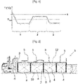
- the figure 1 represents a diagram representing the variations of the temperature T (°C) of a cofferdam as a function of time (t).
- T temperature
- t time
- Significant temperature variations are common when the vessel is sailing.
- a step 1 consists of draining the seawater from the ballast tanks of the ship and the temperatures of the cofferdams adjacent to the cryogenic tanks cool down considerably due to the heat flow from the tank to the cofferdams.
- a step 2 when the ship unloads or uses the LNG, part of the tanks is therefore emptied and the ballast tanks are filled with seawater in order to optimize navigation.
- the temperature of the cofferdams varies via heat transfer from the seawater present in the ballast tanks to the cofferdams.
- stage 2 the temperature in the cofferdam increases.
- the ship thus carries out cycles repeating stage 1 and stage 2. It is therefore difficult to regulate the temperature in the cofferdams.
- the figure 2 represents a ship 3 equipped with an installation for storing and transporting liquefied natural gas which comprises four sealed and thermally insulating tanks 4 .
- Each tank 4 is associated with a degassing mast 5 which is provided on the deck 12 of the vessel 3 and allowing the gas to escape in the vapor phase during an overpressure inside the associated tank 4.
- a machinery compartment 6 which conventionally includes a mixed-fuel steam turbine capable of operating either by combustion of diesel oil or by combustion of evaporation gas coming from the tanks 4.
- the tanks 4, have a longitudinal dimension extending along the longitudinal direction of the ship 3.
- Each tank 4 is bordered at each of its longitudinal ends by a pair of transverse partitions 7, 8 delimiting a space spacer, known by the term "cofferdam" 9.
- the tanks 4 are thus separated from each other by a transverse cofferdam 9. It is thus observed that the tanks 4 are each formed inside a supporting structure which is constituted, on the one hand, by the double hull of the ship 3 and, on the other hand, by one of the transverse partitions 7, 8 of each of the cofferdams 9 bordering the tank 4.
- the ships according to the embodiments of the invention can comprise several types of tank without being limited to a particular tank, for example a tank with membranes making it possible to store liquefied gas.
- the tank 4 has a multilayer structure, not shown, comprising, from the outside inwards, a secondary thermally insulating barrier comprising insulating elements resting against a supporting structure, a secondary sealing membrane resting against the secondary thermally insulating barrier, a primary thermally insulating barrier comprising insulating elements resting against the secondary sealing membrane and a primary sealing membrane intended to be in contact with the liquefied gas contained in the tank.
- the primary sealing membrane defines an internal space of the tank 4 intended to receive the liquefied gas.
- the liquefied gas intended to be stored in the tanks can in particular be a liquefied natural gas (LNG), that is to say a gas mixture mainly comprising methane as well as one or more other hydrocarbons.
- the liquefied gas can also be ethane or a liquefied petroleum gas (LPG), that is to say a mixture of hydrocarbons resulting from petroleum refining comprising essentially propane and butane.
- the picture 3 shows a sectional and perspective view of a transverse cofferdam 19 according to one embodiment in a double-hull ship comprising an outer hull 10 and an inner hull 15.
- the transverse cofferdam 19 comprises a pair of transverse bulkheads delimiting an internal space 13 of the transverse cofferdam 19. Only one of the two transverse partitions 17 is represented on this picture 3 in order to allow visualization of the internal space 13 of the transverse cofferdam 19.
- the transverse cofferdam 19 further comprises an upper wall 37 closing said internal space 13.
- the upper wall 37 can be a wall parallel to the deck upper 12 of the ship.
- a portion of the inner hull 15 located opposite the upper wall 37 defines the bottom of the internal space of the transverse cofferdam 19.
- the ship also has a ballast 41 located outside the transverse cofferdam 19. The ballast 41 is formed by a bottom portion of the space located between the inner hull 15 and the outer hull 10 of the vessel.
- the transverse cofferdam 19 further comprises a structure of stiffeners 14 criss-crossing the internal space 13 in a non-sealed manner.
- the internal space 13 of the transverse cofferdam 19 can contain a heating system 16 making it possible to control the temperature of the transverse cofferdam 19.
- the heating device consists of a tortuous duct in which glycol or another heated antifreeze solution circulates.
- the figure 4 shows an embodiment of a transverse cofferdam 19 further comprising a thermal insulator 40 located in the internal space 23 of the transverse cofferdam.
- the thermal insulation 40 is fixed to the longitudinal walls of the transverse cofferdam 29 including the upper wall 37 and a portion of the internal shell 15. If the transverse cofferdam 19 is located between two tanks 4, only the two transverse partitions 17 are not covered with thermal insulation 40.
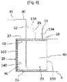
- the figure 6 shows a gas management installation for managing a gaseous atmosphere in the internal space 23 of the transverse cofferdam 29 according to another embodiment.
- Pressure regulator 136 is connected to pressure sensor 35 and inlet valve 32 as before.
- This embodiment differs from the figure 5 in that the vent valve 134 is a mechanically open and close vent valve 134 which is not connected to the pressure regulator 136 and which opens and closes autonomously depending on the pressure present in the internal space 23.
- the evacuation valve with mechanical opening and closing 134 is configured to open when a relative pressure in the internal space 23 becomes greater than the first threshold value and to close again when it returns below. below this value, possibly with a hysteresis.
- the evacuation valve with mechanical opening and closing 134 comprises for example a spring closing mechanism or a valve closing mechanism.
- This evacuation valve with mechanical opening and closing 134 fulfills a safety function because it allows in particular to avoid damage that may be caused by overpressure in the internal space 23 of the transverse cofferdam 29.
- the gas management installation further comprises a gas sampling valve 18.
- the gas sampling valve 18 is mounted on the gas evacuation pipe 33 outside the transverse cofferdam 29 and upstream of the valve. evacuation with mechanical opening and closing 134.
- a sampling of a volume of gas from the internal space 23 of the transverse cofferdam 29 can be carried out in order to analyze the gaseous atmosphere or the temperature of the internal space 23 of the transverse cofferdam 29.
- the embodiments described via the figures are not limited to one type of transverse cofferdam in particular, for example the embodiment described in figure 6 can be applied in the cofferdam described in one of the previous figures.
- the transverse cofferdam 29 comprises a thermal insulator 40 covering the internal surface of the longitudinal walls of the transverse cofferdam 29, including the upper wall 37 and the internal shell 15, over the entire periphery of the internal space 23 in a manner similar to the figure 5 .
- the transverse cofferdam 29 further comprises a thermal insulator 140 on the inner surface of the transverse partition 107, located opposite the tank 4 adjacent.
- the thermal insulation 40 limits the thermal fluxes with the ballast water and the ambient air and the thermal insulation 140 also limits the thermal fluxes with the compartments adjacent to the transverse partition 107, limiting by example the thermal flows with the engine compartment 6 or any other heat source whose temperature is higher than that of the temperature of the tank 4.
- the thermal insulation 40 or 140 can be a glass wool covered on an external face by a vapor barrier, for example a layer of aluminum.
- the glass wool can be fixed by protruding points (not shown) having a first end welded to the walls of the transverse cofferdam 29 and which pass through the glass wool.
- a locking means is added over the glass wool on a second end of the points, for example a tightening clasp.
- the ship 80 comprises a sealed and thermally insulating tank 4 positioned between two cargo tanks 42 filled with a cargo, for example filled with oil.
- the oil has a temperature higher than the temperature of the LNG present in the tank 4.
- the oil is also capable of being heated by a heating device in order to increase its viscosity so as to facilitate its loading or its unloading. It may for example have a temperature of 60°C.
- Each cargo tank 42 is spaced from the watertight and thermally insulating tank 4 by a transverse cofferdam 39.
- the transverse cofferdam 39 is similar to the transverse cofferdam 29 presented above and comprises a thermal insulator on at least the internal surface of a partition transverse, thus limiting the heat fluxes 43 with the adjacent compartments, that is to say limiting the heat fluxes between the tank 4 and the cargo tanks 42, in particular by limiting the transfer of heat from the cargo tanks 42 to the tank 4.
- tank 4 is thermally insulated from petroleum stored in cargo tank 42 at a higher temperature than the liquefied gas stored in tank 4.
- cargo tanks 42 are thermally insulated LNG present in tank 4.
- the ship 90 illustrated in the figure 9 is an LNG-powered vessel.
- the ship 90 can be a container ship or a bulk carrier.
- the bulk carrier is a ship designed for the transport of solid products in bulk.
- the ship 90 comprises, in front of its castle 44 in a longitudinal direction X′-X of the ship 90, one or more chocks 45 for transporting a solid product in bulk.
- the wedges 45 are spaced along the longitudinal direction X′-X of the vessel 90 in a manner known per se. It is specified that only one of these wedges 45, namely the wedge 45 closest to the castle 44, is represented schematically on the figure 9 .
- the ship 90 further comprises a sealed and thermally insulating tank 4 comprising LNG which is intended to supply a propulsion system 46.
- the tank 4 is located behind the cask 6 in the longitudinal direction X′-X.
- the tank 4 is spaced from the heat sources, namely: the cask, the propulsion system 46 and the hold 45, via a transverse cofferdam 49.
- the transverse cofferdam 49 comprises in particular thermal insulation and the management installation gas as previously described.
- a cutaway view of an LNG carrier 70 shows a sealed and insulated tank 71 of generally prismatic shape mounted in the double hull 72 of the ship.
- the wall of the tank 71 comprises a primary leaktight barrier intended to be in contact with the LNG contained in the tank, a secondary leaktight barrier arranged between the primary leaktight barrier and the double hull 72 of the ship, and two insulating barriers arranged respectively between the primary waterproof barrier and the secondary waterproof barrier and between the secondary waterproof barrier and the double hull 72.
- loading/unloading pipes 73 arranged on the upper deck of the ship can be connected, by means of appropriate connectors, to a maritime or port terminal to transfer a cargo of LNG from or to the tank 71.
- the figure 7 represents an example of a maritime terminal comprising a loading and unloading station 75, an underwater pipeline 76 and an installation on land 77.
- the loading and unloading station 75 is a fixed offshore installation comprising a mobile arm 74 and a tower 78 which supports the mobile arm 74.
- the mobile arm 74 carries a bundle of insulated flexible pipes 79 which can be connected to the loading/unloading pipes 73.
- the orientable mobile arm 74 adapts to all sizes of LNG carriers.
- a connecting pipe, not shown, extends inside the tower 78.
- the loading and unloading station 75 allows the loading and unloading of the LNG carrier 70 from or to the shore installation 77.
- This comprises liquefied gas storage tanks 80 and connecting pipes 81 connected by the underwater pipe 76 to the loading or unloading station 75.
- the underwater pipe 76 allows the transfer of the liquefied gas between the loading or unloading station 75 and the shore installation 77 over a large distance, for example 5 km, which makes it possible to keep the LNG carrier 70 at a great distance from the coast during loading and unloading operations.
- pumps on board the ship 70 and/or pumps fitted to the shore installation 77 and/or pumps fitted to the loading and unloading station 75 are used.
- the gas management installation for managing a gaseous atmosphere in the internal space of the transverse cofferdam may for example also comprise branch pipes comprising a manual valve spanning for example the inlet valve or the evacuation valve or even alarm systems (PAL, PAH, PALL, PAHH) linked to the pressure sensor without departing from the scope of the invention.
- branch pipes comprising a manual valve spanning for example the inlet valve or the evacuation valve or even alarm systems (PAL, PAH, PALL, PAHH) linked to the pressure sensor without departing from the scope of the invention.
- Some of the elements, in particular the components of the pressure regulator, can be produced in different forms, in a unitary or distributed manner, by means of hardware and/or software components.
- Material components that can be used are specific integrated circuits ASIC, programmable logic networks FPGA or microprocessors.
- Software components can be written in different programming languages, for example C, C++, Java or VHDL. This list is not exhaustive.
Landscapes
- Engineering & Computer Science (AREA)
- Mechanical Engineering (AREA)
- Chemical & Material Sciences (AREA)
- Combustion & Propulsion (AREA)
- Ocean & Marine Engineering (AREA)
- General Engineering & Computer Science (AREA)
- Filling Or Discharging Of Gas Storage Vessels (AREA)
Applications Claiming Priority (1)
| Application Number | Priority Date | Filing Date | Title |
|---|---|---|---|
| FR2105639A FR3123305A1 (fr) | 2021-05-31 | 2021-05-31 | Navire pour le transport d’un fluide froid |
Publications (2)
| Publication Number | Publication Date |
|---|---|
| EP4098539A1 true EP4098539A1 (de) | 2022-12-07 |
| EP4098539B1 EP4098539B1 (de) | 2024-02-07 |
Family
ID=76730832
Family Applications (1)
| Application Number | Title | Priority Date | Filing Date |
|---|---|---|---|
| EP22173908.9A Active EP4098539B1 (de) | 2021-05-31 | 2022-05-17 | Schiff zum transport oder zur verwendung eines kalten fluids |
Country Status (7)
| Country | Link |
|---|---|
| EP (1) | EP4098539B1 (de) |
| KR (1) | KR20220162083A (de) |
| CN (1) | CN115476967B (de) |
| ES (1) | ES2984355T3 (de) |
| FR (1) | FR3123305A1 (de) |
| PL (1) | PL4098539T3 (de) |
| TW (1) | TW202300406A (de) |
Cited By (1)
| Publication number | Priority date | Publication date | Assignee | Title |
|---|---|---|---|---|
| CN117469594A (zh) * | 2023-10-31 | 2024-01-30 | 青岛科技大学 | 一种lng船利用干隔舱储存捕集的co2的系统 |
Citations (3)
| Publication number | Priority date | Publication date | Assignee | Title |
|---|---|---|---|---|
| JP2006143003A (ja) * | 2004-11-19 | 2006-06-08 | Mitsubishi Heavy Ind Ltd | 液化ガス運搬船 |
| KR20150011439A (ko) * | 2013-07-22 | 2015-02-02 | 대우조선해양 주식회사 | 부유식 해상구조물 및 온도 제어 방법 |
| US20160159438A1 (en) * | 2013-07-22 | 2016-06-09 | Daewoo Shipbuilding & Marine Engineering Co.,Ltd. | Insulation system for floating marine structure |
Family Cites Families (8)
| Publication number | Priority date | Publication date | Assignee | Title |
|---|---|---|---|---|
| GB1407602A (en) * | 1972-01-31 | 1975-09-24 | Conch Int Methane Ltd | Vessels for the transportation of liquefied gases |
| CN101245603B (zh) * | 2008-01-23 | 2010-06-23 | 中国水利水电科学研究院 | 浮式拱围堰及其施工方法 |
| CN102159451B (zh) * | 2008-08-21 | 2014-08-06 | 大宇造船海洋株式会社 | 液化气储罐和包含液化气储罐的海运结构 |
| NO2539222T3 (de) * | 2010-02-22 | 2018-01-20 | ||
| US20160159450A1 (en) * | 2013-07-22 | 2016-06-09 | Daewoo Ship Building & Marine Engineering Co., Ltd | Floating marine structure and method for controlling temperature thereof |
| SG11201805042VA (en) * | 2016-01-12 | 2018-07-30 | Excelerate Liquefaction Solutions Llc | Natural gas liquefaction vessel |
| FR3077617B1 (fr) * | 2018-02-07 | 2022-08-19 | Gaztransport Et Technigaz | Installation pour le stockage et le transport d'un gaz liquefie |
| FR3080832B1 (fr) * | 2018-05-02 | 2020-10-30 | Gaztransport Et Technigaz | Cuve etanche et thermiquement isolante equipee d'une tour de chargement/dechargement |
-
2021
- 2021-05-31 FR FR2105639A patent/FR3123305A1/fr not_active Withdrawn
-
2022
- 2022-05-17 ES ES22173908T patent/ES2984355T3/es active Active
- 2022-05-17 EP EP22173908.9A patent/EP4098539B1/de active Active
- 2022-05-17 PL PL22173908.9T patent/PL4098539T3/pl unknown
- 2022-05-27 TW TW111119892A patent/TW202300406A/zh unknown
- 2022-05-27 CN CN202210592090.2A patent/CN115476967B/zh active Active
- 2022-05-30 KR KR1020220066135A patent/KR20220162083A/ko active Pending
Patent Citations (3)
| Publication number | Priority date | Publication date | Assignee | Title |
|---|---|---|---|---|
| JP2006143003A (ja) * | 2004-11-19 | 2006-06-08 | Mitsubishi Heavy Ind Ltd | 液化ガス運搬船 |
| KR20150011439A (ko) * | 2013-07-22 | 2015-02-02 | 대우조선해양 주식회사 | 부유식 해상구조물 및 온도 제어 방법 |
| US20160159438A1 (en) * | 2013-07-22 | 2016-06-09 | Daewoo Shipbuilding & Marine Engineering Co.,Ltd. | Insulation system for floating marine structure |
Cited By (1)
| Publication number | Priority date | Publication date | Assignee | Title |
|---|---|---|---|---|
| CN117469594A (zh) * | 2023-10-31 | 2024-01-30 | 青岛科技大学 | 一种lng船利用干隔舱储存捕集的co2的系统 |
Also Published As
| Publication number | Publication date |
|---|---|
| CN115476967A (zh) | 2022-12-16 |
| FR3123305A1 (fr) | 2022-12-02 |
| PL4098539T3 (pl) | 2024-08-05 |
| CN115476967B (zh) | 2025-08-29 |
| TW202300406A (zh) | 2023-01-01 |
| EP4098539B1 (de) | 2024-02-07 |
| KR20220162083A (ko) | 2022-12-07 |
| ES2984355T3 (es) | 2024-10-29 |
Similar Documents
| Publication | Publication Date | Title |
|---|---|---|
| EP2758302B1 (de) | Meeresplattform mit externen behältern | |
| EP3129700B1 (de) | Versiegeltes wärmegedämmtes gefäss in einer schwimmenden struktur | |
| EP3271635B1 (de) | Vorrichtung zum kühlen eines flüssiggases | |
| EP3074744B1 (de) | Überwachung einer versiegelten und wärmeisolierten wanne | |
| EP3329172B1 (de) | Vorrichtung zum betreiben einer mit einer wärmeisolierenden barriere eines tanks verbundenen pumpvorrichtung zum speichern eines verflüssigten gases | |
| EP3710741B1 (de) | Vorrichtung zur inertisierung eines flüssiggasspeichertanks für ein schiff zum transport dieses gases | |
| WO2015124536A2 (fr) | Procede et systeme d'inertage d'une paroi d'une cuve de stockage d'un gaz combustible liquefie | |
| WO2016128696A1 (fr) | Gestion des fluides dans une cuve etanche et thermiquement isolante | |
| WO2019162594A2 (fr) | Installation de stockage et de transport d'un fluide cryogenique embarquee sur un navire | |
| EP4098539B1 (de) | Schiff zum transport oder zur verwendung eines kalten fluids | |
| WO2023198853A1 (fr) | Installation pour le stockage et/ou le transport de gaz liquéfié | |
| FR3117572A1 (fr) | Procedes de mise sous gaz et d’essais gaz dans une installation de stockage de gaz liquefie | |
| FR3070673B1 (fr) | Ouvrage flottant comprenant une cuve apte a contenir du gaz combustible liquefie | |
| WO2023198843A1 (fr) | Cuve étanche et thermiquement isolante et procédé de mise sous vide associé | |
| WO2023118320A1 (fr) | Navire comportant un château et une cuve pour le stockage de gaz liquéfié en arrière du château | |
| FR3145397A1 (fr) | Installation de stockage de gaz liquéfié | |
| BE566499A (de) |
Legal Events
| Date | Code | Title | Description |
|---|---|---|---|
| PUAI | Public reference made under article 153(3) epc to a published international application that has entered the european phase |
Free format text: ORIGINAL CODE: 0009012 |
|
| STAA | Information on the status of an ep patent application or granted ep patent |
Free format text: STATUS: THE APPLICATION HAS BEEN PUBLISHED |
|
| AK | Designated contracting states |
Kind code of ref document: A1 Designated state(s): AL AT BE BG CH CY CZ DE DK EE ES FI FR GB GR HR HU IE IS IT LI LT LU LV MC MK MT NL NO PL PT RO RS SE SI SK SM TR |
|
| STAA | Information on the status of an ep patent application or granted ep patent |
Free format text: STATUS: REQUEST FOR EXAMINATION WAS MADE |
|
| 17P | Request for examination filed |
Effective date: 20230504 |
|
| RBV | Designated contracting states (corrected) |
Designated state(s): AL AT BE BG CH CY CZ DE DK EE ES FI FR GB GR HR HU IE IS IT LI LT LU LV MC MK MT NL NO PL PT RO RS SE SI SK SM TR |
|
| GRAP | Despatch of communication of intention to grant a patent |
Free format text: ORIGINAL CODE: EPIDOSNIGR1 |
|
| STAA | Information on the status of an ep patent application or granted ep patent |
Free format text: STATUS: GRANT OF PATENT IS INTENDED |
|
| INTG | Intention to grant announced |
Effective date: 20231017 |
|
| GRAS | Grant fee paid |
Free format text: ORIGINAL CODE: EPIDOSNIGR3 |
|
| GRAA | (expected) grant |
Free format text: ORIGINAL CODE: 0009210 |
|
| STAA | Information on the status of an ep patent application or granted ep patent |
Free format text: STATUS: THE PATENT HAS BEEN GRANTED |
|
| AK | Designated contracting states |
Kind code of ref document: B1 Designated state(s): AL AT BE BG CH CY CZ DE DK EE ES FI FR GB GR HR HU IE IS IT LI LT LU LV MC MK MT NL NO PL PT RO RS SE SI SK SM TR |
|
| REG | Reference to a national code |
Ref country code: GB Ref legal event code: FG4D Free format text: NOT ENGLISH |
|
| REG | Reference to a national code |
Ref country code: CH Ref legal event code: EP |
|
| REG | Reference to a national code |
Ref country code: DE Ref legal event code: R096 Ref document number: 602022001844 Country of ref document: DE |
|
| REG | Reference to a national code |
Ref country code: IE Ref legal event code: FG4D Free format text: LANGUAGE OF EP DOCUMENT: FRENCH |
|
| REG | Reference to a national code |
Ref country code: LT Ref legal event code: MG9D |
|
| REG | Reference to a national code |
Ref country code: NL Ref legal event code: MP Effective date: 20240207 |
|
| PG25 | Lapsed in a contracting state [announced via postgrant information from national office to epo] |
Ref country code: IS Free format text: LAPSE BECAUSE OF FAILURE TO SUBMIT A TRANSLATION OF THE DESCRIPTION OR TO PAY THE FEE WITHIN THE PRESCRIBED TIME-LIMIT Effective date: 20240607 |
|
| PG25 | Lapsed in a contracting state [announced via postgrant information from national office to epo] |
Ref country code: LT Free format text: LAPSE BECAUSE OF FAILURE TO SUBMIT A TRANSLATION OF THE DESCRIPTION OR TO PAY THE FEE WITHIN THE PRESCRIBED TIME-LIMIT Effective date: 20240207 |
|
| PG25 | Lapsed in a contracting state [announced via postgrant information from national office to epo] |
Ref country code: GR Free format text: LAPSE BECAUSE OF FAILURE TO SUBMIT A TRANSLATION OF THE DESCRIPTION OR TO PAY THE FEE WITHIN THE PRESCRIBED TIME-LIMIT Effective date: 20240508 |
|
| REG | Reference to a national code |
Ref country code: AT Ref legal event code: MK05 Ref document number: 1655210 Country of ref document: AT Kind code of ref document: T Effective date: 20240207 |
|
| PG25 | Lapsed in a contracting state [announced via postgrant information from national office to epo] |
Ref country code: HR Free format text: LAPSE BECAUSE OF FAILURE TO SUBMIT A TRANSLATION OF THE DESCRIPTION OR TO PAY THE FEE WITHIN THE PRESCRIBED TIME-LIMIT Effective date: 20240207 Ref country code: RS Free format text: LAPSE BECAUSE OF FAILURE TO SUBMIT A TRANSLATION OF THE DESCRIPTION OR TO PAY THE FEE WITHIN THE PRESCRIBED TIME-LIMIT Effective date: 20240507 Ref country code: NL Free format text: LAPSE BECAUSE OF FAILURE TO SUBMIT A TRANSLATION OF THE DESCRIPTION OR TO PAY THE FEE WITHIN THE PRESCRIBED TIME-LIMIT Effective date: 20240207 |
|
| PG25 | Lapsed in a contracting state [announced via postgrant information from national office to epo] |
Ref country code: AT Free format text: LAPSE BECAUSE OF FAILURE TO SUBMIT A TRANSLATION OF THE DESCRIPTION OR TO PAY THE FEE WITHIN THE PRESCRIBED TIME-LIMIT Effective date: 20240207 |
|
| PG25 | Lapsed in a contracting state [announced via postgrant information from national office to epo] |
Ref country code: RS Free format text: LAPSE BECAUSE OF FAILURE TO SUBMIT A TRANSLATION OF THE DESCRIPTION OR TO PAY THE FEE WITHIN THE PRESCRIBED TIME-LIMIT Effective date: 20240507 Ref country code: NL Free format text: LAPSE BECAUSE OF FAILURE TO SUBMIT A TRANSLATION OF THE DESCRIPTION OR TO PAY THE FEE WITHIN THE PRESCRIBED TIME-LIMIT Effective date: 20240207 Ref country code: LT Free format text: LAPSE BECAUSE OF FAILURE TO SUBMIT A TRANSLATION OF THE DESCRIPTION OR TO PAY THE FEE WITHIN THE PRESCRIBED TIME-LIMIT Effective date: 20240207 Ref country code: IS Free format text: LAPSE BECAUSE OF FAILURE TO SUBMIT A TRANSLATION OF THE DESCRIPTION OR TO PAY THE FEE WITHIN THE PRESCRIBED TIME-LIMIT Effective date: 20240607 Ref country code: HR Free format text: LAPSE BECAUSE OF FAILURE TO SUBMIT A TRANSLATION OF THE DESCRIPTION OR TO PAY THE FEE WITHIN THE PRESCRIBED TIME-LIMIT Effective date: 20240207 Ref country code: GR Free format text: LAPSE BECAUSE OF FAILURE TO SUBMIT A TRANSLATION OF THE DESCRIPTION OR TO PAY THE FEE WITHIN THE PRESCRIBED TIME-LIMIT Effective date: 20240508 Ref country code: FI Free format text: LAPSE BECAUSE OF FAILURE TO SUBMIT A TRANSLATION OF THE DESCRIPTION OR TO PAY THE FEE WITHIN THE PRESCRIBED TIME-LIMIT Effective date: 20240207 Ref country code: BG Free format text: LAPSE BECAUSE OF FAILURE TO SUBMIT A TRANSLATION OF THE DESCRIPTION OR TO PAY THE FEE WITHIN THE PRESCRIBED TIME-LIMIT Effective date: 20240207 Ref country code: AT Free format text: LAPSE BECAUSE OF FAILURE TO SUBMIT A TRANSLATION OF THE DESCRIPTION OR TO PAY THE FEE WITHIN THE PRESCRIBED TIME-LIMIT Effective date: 20240207 |
|
| PG25 | Lapsed in a contracting state [announced via postgrant information from national office to epo] |
Ref country code: PT Free format text: LAPSE BECAUSE OF FAILURE TO SUBMIT A TRANSLATION OF THE DESCRIPTION OR TO PAY THE FEE WITHIN THE PRESCRIBED TIME-LIMIT Effective date: 20240607 |
|
| PG25 | Lapsed in a contracting state [announced via postgrant information from national office to epo] |
Ref country code: SE Free format text: LAPSE BECAUSE OF FAILURE TO SUBMIT A TRANSLATION OF THE DESCRIPTION OR TO PAY THE FEE WITHIN THE PRESCRIBED TIME-LIMIT Effective date: 20240207 Ref country code: PT Free format text: LAPSE BECAUSE OF FAILURE TO SUBMIT A TRANSLATION OF THE DESCRIPTION OR TO PAY THE FEE WITHIN THE PRESCRIBED TIME-LIMIT Effective date: 20240607 Ref country code: LV Free format text: LAPSE BECAUSE OF FAILURE TO SUBMIT A TRANSLATION OF THE DESCRIPTION OR TO PAY THE FEE WITHIN THE PRESCRIBED TIME-LIMIT Effective date: 20240207 |
|
| PG25 | Lapsed in a contracting state [announced via postgrant information from national office to epo] |
Ref country code: DK Free format text: LAPSE BECAUSE OF FAILURE TO SUBMIT A TRANSLATION OF THE DESCRIPTION OR TO PAY THE FEE WITHIN THE PRESCRIBED TIME-LIMIT Effective date: 20240207 |
|
| PG25 | Lapsed in a contracting state [announced via postgrant information from national office to epo] |
Ref country code: SM Free format text: LAPSE BECAUSE OF FAILURE TO SUBMIT A TRANSLATION OF THE DESCRIPTION OR TO PAY THE FEE WITHIN THE PRESCRIBED TIME-LIMIT Effective date: 20240207 |
|
| PG25 | Lapsed in a contracting state [announced via postgrant information from national office to epo] |
Ref country code: EE Free format text: LAPSE BECAUSE OF FAILURE TO SUBMIT A TRANSLATION OF THE DESCRIPTION OR TO PAY THE FEE WITHIN THE PRESCRIBED TIME-LIMIT Effective date: 20240207 Ref country code: CZ Free format text: LAPSE BECAUSE OF FAILURE TO SUBMIT A TRANSLATION OF THE DESCRIPTION OR TO PAY THE FEE WITHIN THE PRESCRIBED TIME-LIMIT Effective date: 20240207 |
|
| PG25 | Lapsed in a contracting state [announced via postgrant information from national office to epo] |
Ref country code: SK Free format text: LAPSE BECAUSE OF FAILURE TO SUBMIT A TRANSLATION OF THE DESCRIPTION OR TO PAY THE FEE WITHIN THE PRESCRIBED TIME-LIMIT Effective date: 20240207 |
|
| REG | Reference to a national code |
Ref country code: ES Ref legal event code: FG2A Ref document number: 2984355 Country of ref document: ES Kind code of ref document: T3 Effective date: 20241029 |
|
| PG25 | Lapsed in a contracting state [announced via postgrant information from national office to epo] |
Ref country code: SM Free format text: LAPSE BECAUSE OF FAILURE TO SUBMIT A TRANSLATION OF THE DESCRIPTION OR TO PAY THE FEE WITHIN THE PRESCRIBED TIME-LIMIT Effective date: 20240207 Ref country code: SK Free format text: LAPSE BECAUSE OF FAILURE TO SUBMIT A TRANSLATION OF THE DESCRIPTION OR TO PAY THE FEE WITHIN THE PRESCRIBED TIME-LIMIT Effective date: 20240207 Ref country code: EE Free format text: LAPSE BECAUSE OF FAILURE TO SUBMIT A TRANSLATION OF THE DESCRIPTION OR TO PAY THE FEE WITHIN THE PRESCRIBED TIME-LIMIT Effective date: 20240207 Ref country code: DK Free format text: LAPSE BECAUSE OF FAILURE TO SUBMIT A TRANSLATION OF THE DESCRIPTION OR TO PAY THE FEE WITHIN THE PRESCRIBED TIME-LIMIT Effective date: 20240207 Ref country code: CZ Free format text: LAPSE BECAUSE OF FAILURE TO SUBMIT A TRANSLATION OF THE DESCRIPTION OR TO PAY THE FEE WITHIN THE PRESCRIBED TIME-LIMIT Effective date: 20240207 |
|
| REG | Reference to a national code |
Ref country code: DE Ref legal event code: R097 Ref document number: 602022001844 Country of ref document: DE |
|
| PLBE | No opposition filed within time limit |
Free format text: ORIGINAL CODE: 0009261 |
|
| STAA | Information on the status of an ep patent application or granted ep patent |
Free format text: STATUS: NO OPPOSITION FILED WITHIN TIME LIMIT |
|
| PG25 | Lapsed in a contracting state [announced via postgrant information from national office to epo] |
Ref country code: MC Free format text: LAPSE BECAUSE OF FAILURE TO SUBMIT A TRANSLATION OF THE DESCRIPTION OR TO PAY THE FEE WITHIN THE PRESCRIBED TIME-LIMIT Effective date: 20240207 |
|
| 26N | No opposition filed |
Effective date: 20241108 |
|
| PG25 | Lapsed in a contracting state [announced via postgrant information from national office to epo] |
Ref country code: LU Free format text: LAPSE BECAUSE OF NON-PAYMENT OF DUE FEES Effective date: 20240517 |
|
| PG25 | Lapsed in a contracting state [announced via postgrant information from national office to epo] |
Ref country code: MC Free format text: LAPSE BECAUSE OF FAILURE TO SUBMIT A TRANSLATION OF THE DESCRIPTION OR TO PAY THE FEE WITHIN THE PRESCRIBED TIME-LIMIT Effective date: 20240207 Ref country code: LU Free format text: LAPSE BECAUSE OF NON-PAYMENT OF DUE FEES Effective date: 20240517 |
|
| REG | Reference to a national code |
Ref country code: BE Ref legal event code: MM Effective date: 20240531 |
|
| PG25 | Lapsed in a contracting state [announced via postgrant information from national office to epo] |
Ref country code: IE Free format text: LAPSE BECAUSE OF NON-PAYMENT OF DUE FEES Effective date: 20240517 |
|
| PG25 | Lapsed in a contracting state [announced via postgrant information from national office to epo] |
Ref country code: SI Free format text: LAPSE BECAUSE OF FAILURE TO SUBMIT A TRANSLATION OF THE DESCRIPTION OR TO PAY THE FEE WITHIN THE PRESCRIBED TIME-LIMIT Effective date: 20240207 Ref country code: BE Free format text: LAPSE BECAUSE OF NON-PAYMENT OF DUE FEES Effective date: 20240531 |
|
| PGFP | Annual fee paid to national office [announced via postgrant information from national office to epo] |
Ref country code: PL Payment date: 20250424 Year of fee payment: 4 Ref country code: DE Payment date: 20250513 Year of fee payment: 4 |
|
| PGFP | Annual fee paid to national office [announced via postgrant information from national office to epo] |
Ref country code: ES Payment date: 20250610 Year of fee payment: 4 |
|
| PGFP | Annual fee paid to national office [announced via postgrant information from national office to epo] |
Ref country code: NO Payment date: 20250425 Year of fee payment: 4 |
|
| PGFP | Annual fee paid to national office [announced via postgrant information from national office to epo] |
Ref country code: IT Payment date: 20250531 Year of fee payment: 4 |
|
| PGFP | Annual fee paid to national office [announced via postgrant information from national office to epo] |
Ref country code: FR Payment date: 20250530 Year of fee payment: 4 |
|
| PGFP | Annual fee paid to national office [announced via postgrant information from national office to epo] |
Ref country code: RO Payment date: 20250506 Year of fee payment: 4 |
|
| PG25 | Lapsed in a contracting state [announced via postgrant information from national office to epo] |
Ref country code: CY Free format text: LAPSE BECAUSE OF FAILURE TO SUBMIT A TRANSLATION OF THE DESCRIPTION OR TO PAY THE FEE WITHIN THE PRESCRIBED TIME-LIMIT; INVALID AB INITIO Effective date: 20220517 |
|
| PG25 | Lapsed in a contracting state [announced via postgrant information from national office to epo] |
Ref country code: HU Free format text: LAPSE BECAUSE OF FAILURE TO SUBMIT A TRANSLATION OF THE DESCRIPTION OR TO PAY THE FEE WITHIN THE PRESCRIBED TIME-LIMIT; INVALID AB INITIO Effective date: 20220517 |
|
| REG | Reference to a national code |
Ref country code: CH Ref legal event code: H13 Free format text: ST27 STATUS EVENT CODE: U-0-0-H10-H13 (AS PROVIDED BY THE NATIONAL OFFICE) Effective date: 20251223 |
|
| PG25 | Lapsed in a contracting state [announced via postgrant information from national office to epo] |
Ref country code: CH Free format text: LAPSE BECAUSE OF NON-PAYMENT OF DUE FEES Effective date: 20250531 |