EP4098459B1 - Schwerlastreifen - Google Patents
Schwerlastreifen Download PDFInfo
- Publication number
- EP4098459B1 EP4098459B1 EP22174106.9A EP22174106A EP4098459B1 EP 4098459 B1 EP4098459 B1 EP 4098459B1 EP 22174106 A EP22174106 A EP 22174106A EP 4098459 B1 EP4098459 B1 EP 4098459B1
- Authority
- EP
- European Patent Office
- Prior art keywords
- belt
- belt ply
- tire
- ply
- cord
- Prior art date
- Legal status (The legal status is an assumption and is not a legal conclusion. Google has not performed a legal analysis and makes no representation as to the accuracy of the status listed.)
- Active
Links
Images


Classifications
-
- B—PERFORMING OPERATIONS; TRANSPORTING
- B60—VEHICLES IN GENERAL
- B60C—VEHICLE TYRES; TYRE INFLATION; TYRE CHANGING; CONNECTING VALVES TO INFLATABLE ELASTIC BODIES IN GENERAL; DEVICES OR ARRANGEMENTS RELATED TO TYRES
- B60C9/00—Reinforcements or ply arrangement of pneumatic tyres
- B60C9/18—Structure or arrangement of belts or breakers, crown-reinforcing or cushioning layers
- B60C9/20—Structure or arrangement of belts or breakers, crown-reinforcing or cushioning layers built-up from rubberised plies each having all cords arranged substantially parallel
-
- B—PERFORMING OPERATIONS; TRANSPORTING
- B60—VEHICLES IN GENERAL
- B60C—VEHICLE TYRES; TYRE INFLATION; TYRE CHANGING; CONNECTING VALVES TO INFLATABLE ELASTIC BODIES IN GENERAL; DEVICES OR ARRANGEMENTS RELATED TO TYRES
- B60C9/00—Reinforcements or ply arrangement of pneumatic tyres
- B60C9/18—Structure or arrangement of belts or breakers, crown-reinforcing or cushioning layers
- B60C9/20—Structure or arrangement of belts or breakers, crown-reinforcing or cushioning layers built-up from rubberised plies each having all cords arranged substantially parallel
- B60C9/2003—Structure or arrangement of belts or breakers, crown-reinforcing or cushioning layers built-up from rubberised plies each having all cords arranged substantially parallel characterised by the materials of the belt cords
- B60C9/2006—Structure or arrangement of belts or breakers, crown-reinforcing or cushioning layers built-up from rubberised plies each having all cords arranged substantially parallel characterised by the materials of the belt cords consisting of steel cord plies only
-
- B—PERFORMING OPERATIONS; TRANSPORTING
- B60—VEHICLES IN GENERAL
- B60C—VEHICLE TYRES; TYRE INFLATION; TYRE CHANGING; CONNECTING VALVES TO INFLATABLE ELASTIC BODIES IN GENERAL; DEVICES OR ARRANGEMENTS RELATED TO TYRES
- B60C9/00—Reinforcements or ply arrangement of pneumatic tyres
- B60C9/18—Structure or arrangement of belts or breakers, crown-reinforcing or cushioning layers
- B60C9/1821—Structure or arrangement of belts or breakers, crown-reinforcing or cushioning layers comprising discrete fibres or filaments
-
- B—PERFORMING OPERATIONS; TRANSPORTING
- B60—VEHICLES IN GENERAL
- B60C—VEHICLE TYRES; TYRE INFLATION; TYRE CHANGING; CONNECTING VALVES TO INFLATABLE ELASTIC BODIES IN GENERAL; DEVICES OR ARRANGEMENTS RELATED TO TYRES
- B60C9/00—Reinforcements or ply arrangement of pneumatic tyres
- B60C9/18—Structure or arrangement of belts or breakers, crown-reinforcing or cushioning layers
- B60C9/28—Structure or arrangement of belts or breakers, crown-reinforcing or cushioning layers characterised by the belt or breaker dimensions or curvature relative to carcass
-
- B—PERFORMING OPERATIONS; TRANSPORTING
- B60—VEHICLES IN GENERAL
- B60C—VEHICLE TYRES; TYRE INFLATION; TYRE CHANGING; CONNECTING VALVES TO INFLATABLE ELASTIC BODIES IN GENERAL; DEVICES OR ARRANGEMENTS RELATED TO TYRES
- B60C9/00—Reinforcements or ply arrangement of pneumatic tyres
- B60C9/18—Structure or arrangement of belts or breakers, crown-reinforcing or cushioning layers
- B60C2009/1828—Structure or arrangement of belts or breakers, crown-reinforcing or cushioning layers characterised by special physical properties of the belt ply
-
- B—PERFORMING OPERATIONS; TRANSPORTING
- B60—VEHICLES IN GENERAL
- B60C—VEHICLE TYRES; TYRE INFLATION; TYRE CHANGING; CONNECTING VALVES TO INFLATABLE ELASTIC BODIES IN GENERAL; DEVICES OR ARRANGEMENTS RELATED TO TYRES
- B60C9/00—Reinforcements or ply arrangement of pneumatic tyres
- B60C9/18—Structure or arrangement of belts or breakers, crown-reinforcing or cushioning layers
- B60C9/20—Structure or arrangement of belts or breakers, crown-reinforcing or cushioning layers built-up from rubberised plies each having all cords arranged substantially parallel
- B60C2009/2012—Structure or arrangement of belts or breakers, crown-reinforcing or cushioning layers built-up from rubberised plies each having all cords arranged substantially parallel with particular configuration of the belt cords in the respective belt layers
- B60C2009/2016—Structure or arrangement of belts or breakers, crown-reinforcing or cushioning layers built-up from rubberised plies each having all cords arranged substantially parallel with particular configuration of the belt cords in the respective belt layers comprising cords at an angle of 10 to 30 degrees to the circumferential direction
-
- B—PERFORMING OPERATIONS; TRANSPORTING
- B60—VEHICLES IN GENERAL
- B60C—VEHICLE TYRES; TYRE INFLATION; TYRE CHANGING; CONNECTING VALVES TO INFLATABLE ELASTIC BODIES IN GENERAL; DEVICES OR ARRANGEMENTS RELATED TO TYRES
- B60C9/00—Reinforcements or ply arrangement of pneumatic tyres
- B60C9/18—Structure or arrangement of belts or breakers, crown-reinforcing or cushioning layers
- B60C9/20—Structure or arrangement of belts or breakers, crown-reinforcing or cushioning layers built-up from rubberised plies each having all cords arranged substantially parallel
- B60C2009/2012—Structure or arrangement of belts or breakers, crown-reinforcing or cushioning layers built-up from rubberised plies each having all cords arranged substantially parallel with particular configuration of the belt cords in the respective belt layers
- B60C2009/2019—Structure or arrangement of belts or breakers, crown-reinforcing or cushioning layers built-up from rubberised plies each having all cords arranged substantially parallel with particular configuration of the belt cords in the respective belt layers comprising cords at an angle of 30 to 60 degrees to the circumferential direction
-
- B—PERFORMING OPERATIONS; TRANSPORTING
- B60—VEHICLES IN GENERAL
- B60C—VEHICLE TYRES; TYRE INFLATION; TYRE CHANGING; CONNECTING VALVES TO INFLATABLE ELASTIC BODIES IN GENERAL; DEVICES OR ARRANGEMENTS RELATED TO TYRES
- B60C9/00—Reinforcements or ply arrangement of pneumatic tyres
- B60C9/18—Structure or arrangement of belts or breakers, crown-reinforcing or cushioning layers
- B60C9/20—Structure or arrangement of belts or breakers, crown-reinforcing or cushioning layers built-up from rubberised plies each having all cords arranged substantially parallel
- B60C2009/2061—Physical properties or dimensions of the belt coating rubber
- B60C2009/2067—Thickness
-
- B—PERFORMING OPERATIONS; TRANSPORTING
- B60—VEHICLES IN GENERAL
- B60C—VEHICLE TYRES; TYRE INFLATION; TYRE CHANGING; CONNECTING VALVES TO INFLATABLE ELASTIC BODIES IN GENERAL; DEVICES OR ARRANGEMENTS RELATED TO TYRES
- B60C9/00—Reinforcements or ply arrangement of pneumatic tyres
- B60C9/18—Structure or arrangement of belts or breakers, crown-reinforcing or cushioning layers
- B60C9/20—Structure or arrangement of belts or breakers, crown-reinforcing or cushioning layers built-up from rubberised plies each having all cords arranged substantially parallel
- B60C2009/2074—Physical properties or dimension of the belt cord
- B60C2009/2077—Diameters of the cords; Linear density thereof
-
- B—PERFORMING OPERATIONS; TRANSPORTING
- B60—VEHICLES IN GENERAL
- B60C—VEHICLE TYRES; TYRE INFLATION; TYRE CHANGING; CONNECTING VALVES TO INFLATABLE ELASTIC BODIES IN GENERAL; DEVICES OR ARRANGEMENTS RELATED TO TYRES
- B60C9/00—Reinforcements or ply arrangement of pneumatic tyres
- B60C9/18—Structure or arrangement of belts or breakers, crown-reinforcing or cushioning layers
- B60C9/20—Structure or arrangement of belts or breakers, crown-reinforcing or cushioning layers built-up from rubberised plies each having all cords arranged substantially parallel
- B60C2009/2074—Physical properties or dimension of the belt cord
- B60C2009/2083—Density in width direction
-
- B—PERFORMING OPERATIONS; TRANSPORTING
- B60—VEHICLES IN GENERAL
- B60C—VEHICLE TYRES; TYRE INFLATION; TYRE CHANGING; CONNECTING VALVES TO INFLATABLE ELASTIC BODIES IN GENERAL; DEVICES OR ARRANGEMENTS RELATED TO TYRES
- B60C11/00—Tyre tread bands; Tread patterns; Anti-skid inserts
- B60C11/0008—Tyre tread bands; Tread patterns; Anti-skid inserts characterised by the tread rubber
- B60C2011/0016—Physical properties or dimensions
- B60C2011/0033—Thickness of the tread
-
- B—PERFORMING OPERATIONS; TRANSPORTING
- B60—VEHICLES IN GENERAL
- B60C—VEHICLE TYRES; TYRE INFLATION; TYRE CHANGING; CONNECTING VALVES TO INFLATABLE ELASTIC BODIES IN GENERAL; DEVICES OR ARRANGEMENTS RELATED TO TYRES
- B60C2200/00—Tyres specially adapted for particular applications
- B60C2200/06—Tyres specially adapted for particular applications for heavy duty vehicles
-
- Y—GENERAL TAGGING OF NEW TECHNOLOGICAL DEVELOPMENTS; GENERAL TAGGING OF CROSS-SECTIONAL TECHNOLOGIES SPANNING OVER SEVERAL SECTIONS OF THE IPC; TECHNICAL SUBJECTS COVERED BY FORMER USPC CROSS-REFERENCE ART COLLECTIONS [XRACs] AND DIGESTS
- Y02—TECHNOLOGIES OR APPLICATIONS FOR MITIGATION OR ADAPTATION AGAINST CLIMATE CHANGE
- Y02T—CLIMATE CHANGE MITIGATION TECHNOLOGIES RELATED TO TRANSPORTATION
- Y02T10/00—Road transport of goods or passengers
- Y02T10/80—Technologies aiming to reduce greenhouse gasses emissions common to all road transportation technologies
- Y02T10/86—Optimisation of rolling resistance, e.g. weight reduction
Definitions
- the present invention relates to a heavy-duty tire.
- Patent Document 1 discloses a heavy-duty pneumatic tire which is provided, on the radially outside of a crown portion of the carcass, with an inclined belt which is composed of a first belt layer and a second belt layer, and a reinforcing element of the first belt layer and a reinforcing element of the second belt layer incline with respect to a tire circumferential direction so as to cross each other between the layers.
- Patent Document 1 Japanese Patent Application Publication No. 2020-063051
- a heavy-duty tire in accordance with the preamble of claim 1 is known from JP 2003 211911 A .
- Related heavy-duty tires are known from WO 2018/104667 A1 and DE 10 2014 224497 A1 .
- the present invention was made in view of the above circumstances, and an object of the present invention is to provide a heavy-duty tire capable of improving the rolling resistance performance as well as the durability performance.
- a heavy-duty tire comprises: a tread portion; a pair of axially spaced bead portions each with a bead core therein; a pair of sidewall portions extending between the tread edges and the bead portions; a carcass extending between the bead cores in the bead portions through the tread portion and the sidewall portions; and a tread reinforcing belt disposed radially outside the carcass in the tread portion, wherein
- the cord count E4 of the fourth belt ply is in a range from 65% to 85% of the cord count E3 of the third belt ply.
- the first distance L1 is in a range from 80% to 100% of the second distance L2.
- the belt cords of the fourth belt ply have a cord diameter D4
- the belt cords of the third belt ply have a cord diameter D3
- the cord diameter D4 is in a range from 65% to 100% of the cord diameter D3.
- the belt cords of the fourth belt ply are inclined at an angle in a range from 30 to 60 degrees with respect to the tire equatorial plane.
- the tread portion is provided with a main groove extending in the tire circumferential direction, and a shortest distance in the tire radial direction between the belt cords of the fourth belt ply and the bottom of the main groove is in a range from 3 to 7 mm.
- the belt cords of the first belt ply are inclined at an angle in a range from 30 to 60 degrees with respect to the tire equatorial plane
- the belt cords of the second belt ply are inclined at an angle in a range from 15 to 25 degrees with respect to the tire equatorial plane
- the belt cords of the third belt ply are inclined at an angle in a range from 15 to 25 degrees with respect to the tire equatorial plane.
- the width in the tire axial direction, of the fourth belt ply is in a range from 25% to 75% of a tread width.
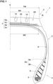
- FIG. 1 shows a meridian cross section including the tire rotation axis (not shown), of a right half of a heavy-duty tire 1 (hereinafter, may be simply referred to as the tire 1).
- the tire 1 in the present embodiment of the invention is designed for use with, for example, a truck or a bus.
- the tire 1 in the present embodiment of the invention comprises: a tread portion 2; a pair of axially spaced bead portions 4 each with a bead core 5 therein; a pair of sidewall portions 3 extending between tread edges 2t and the bead portions 4; a carcass 6 extending between the bead cores 5 in the bead portions 4 through the tread portion 2 and the sidewall portions 3; and a tread reinforcing belt 7 disposed radially outside the carcass 6 in the tread portion 2.
- tread edges 2t are the axial outermost edges of the ground contacting patch of the tire which occurs under a normally inflated loaded state when the camber angle of the tire is zero.
- the undermentioned tread width TW is the width measured under a normally inflated unloaded state, as the axial distance between the tread edges 2t determined as above.
- the normally inflated unloaded state is such that the tire is mounted on a standard wheel rim and inflate to a standard pressure but loaded with no tire load.
- the normally inflated loaded state is such that the tire is mounted on the standard wheel rim and inflated to the standard pressure and loaded with a standard tire load.
- the standard wheel rim is a wheel rim officially approved or recommended for the tire by standards organizations, i.e. JATMA (Japan and Asia), T&RA (North America), ETRTO (Europe), TRAA (Australia), STRO (Scandinavia), ALAPA (Latin America), ITTAC (India) and the like which are effective in the area where the tire is manufactured, sold or used.
- the standard pressure and the standard tire load are the maximum air pressure and the maximum tire load for the tire specified by the same organization in the Air-pressure/Maximum-load Table or similar list.
- the standard wheel rim is the "standard rim” specified in JATMA, the "Measuring Rim” in ETRTO, the “Design Rim” in TRA or the like.
- the standard pressure is the "maximum air pressure” in JATMA, the “Inflation Pressure” in ETRTO, the maximum pressure given in the "Tire Load Limits at Various Cold Inflation Pressures” table in TRA or the like.
- the standard tire load is the "maximum load capacity" in JATMA, the “Load Capacity” in ETRTO, the maximum value given in the above-mentioned table in TRA or the like.
- the tread portion 2 is provided with a tread rubber 2G disposed on the radially outer side of the belt 7.
- the tread rubber 2G is provided with main grooves 14 extending in the tire circumferential direction.
- the main grooves 14 are recessed inward in the tire radial direction from the radially outer surface of the tread portion 2.
- the carcass 6 is composed of at least one, in the present embodiment of the invention, only one carcass ply 6A.
- the carcass ply 6A extends between the bead portions 4 through the tread portion 2 and the sidewall portions 3 and is turned up around the bead core 5 in each bead portion 4 so as to form a pair of turned up portions 6b and a main portion 6a therebetween.
- Each of the bead portions 4 is provided, between the turned up portion 6b and the main portion 6a, with a rubber bead apex 8 extending radially outwardly from the bead core 5.
- the carcass ply 6A is composed of carcass cords (not shown), for example, arranged radially at an angle of 75 to 90 degrees with respect to the tire equatorial plane C.
- steel cords can be suitably used.
- the belt 7 is composed of a plurality of belt plies each composed of parallel belt cords 11 covered with a topping rubber 12.
- each belt cord 11 is made of a plurality of steel filaments (not shown) twisted together.
- the belt cords 11 is not limited to such a structure formed from the twisted steel filaments, and may be a single steel filament, for example.
- the belt 7 is composed of a first belt ply 7A, a second belt ply 7B, a third belt ply 7C and a fourth belt ply 7D arranged in this order from the inside to the outside in the tire radial direction.
- the second belt ply 7B has a largest axial width W2
- the fourth belt ply 7D has a smallest axial width W4.
- FIG. 3 is a development view of the belt, wherein the belt cords 11 are shown in a simplified manner, and some of them are omitted.
- each of the first to fourth belt plies 7A to 7D is composed of parallel belt cords 11 inclined at an angle ( ⁇ 1, ⁇ 2, ⁇ 3, ⁇ 4) with respect to the tire equatorial plane C.
- the belt cords 11 of the first belt ply 7A and the belt cords 11 of the second belt ply 7B are inclined with respect to the tire equatorial plane C to one side in the tire axial direction
- the belt cords 11 of the third belt ply 7C and the belt cords 11 of the fourth belt ply 7D are inclined with respect to the tire equatorial plane C to the other side in the tire axial direction.
- the angle ⁇ 1 of the belt cords 11 of the first belt ply 7A with respect to the tire equatorial plane C is set to a value between the angle ⁇ 2 of the belt cords 11 of the second belt ply 7B with respect to the tire equatorial plane C, and the above-mentioned angle of the carcass cords (not shown) of the carcass ply 6A.
- Such first belt ply 7A can increase the rigidity of the belt, while alleviating the shear strain caused between the carcass ply 6A and the second belt ply 7B, and can further reinforce the tread portion 2.
- the angle ⁇ 1 is set in a range from 30 to 60 degrees.
- the belt cords 11 of the second belt ply 7B cross the belt cords 11 of the third belt ply 7C.
- Such second belt ply 7B and third belt ply 7C can increase the binding force in the tire circumferential direction, therefore, the second belt ply 7B and the third belt ply 7C can firmly reinforce the tread portion 2 with its hoop effect, and can improve the durability performance.
- the angle ⁇ 2 of the belt cords 11 of the second belt ply 7B with respect to the tire equatorial plane C is set in a range from 15 to 25 degrees
- the angle ⁇ 3 of the belt cords 11 of the third belt ply 7C with respect to the tire equatorial plane C is set in a range from 15 to 25 degrees.
- the tread portion 2 can be firmly reinforced and the durability performance can be improved.
- angles ⁇ 2 and ⁇ 3 are set to not less than 15 degrees, it is possible to prevent the binding force in the tire circumferential direction from becoming unnecessarily large, so the riding comfort can be maintained.
- angles ⁇ 2 and ⁇ 3 are preferably not more than 22 degrees, and preferably not less than 18 degrees.
- the fourth belt ply 7D is located on the outermost side in the tire radial direction in the belt 7 in order to improve the cut resistance of the tread portion 2.
- a first distance L1 is set to be not more than a second distance L2, wherein
- Each of the first distance L1, the second distance L2 and the undermentioned third distance L3 may be defined by an average value of the distance between the belt cords 11 adjacent in the tire radial direction, which is averaged over the entire width of a region 20 where all of the first to fourth belt plies 7A to 7D overlap in the tire radial direction, in other words, all of the first to fourth belt plies 7A to 7D exist.
- region 20 corresponds to a region having the width W4 (shown in FIG. 1 ) of the narrowest fourth belt ply 7D.
- the first distance L1 is not more than the second distance L2
- the fourth belt ply 7D affects the rolling resistance performance of the tire as compared with the first to third belt plies 7A to 7C disposed radially inside the fourth belt ply 7D. Therefore, in the tire 1 of the present embodiment of the invention, as the first distance L1 is set to not more than the second distance L2, an increase in energy loss of the belt 7 (fourth belt ply 7D) can be prevented, and thereby, the rolling resistance performance is maintained.
- the first distance L1 is set in a range from 80% to 100% of the second distance L2.
- the rolling resistance performance can be maintained.
- the first distance L1 By setting the first distance L1 to not less than 80% of the second distance L2, it is possible to suppress the belt cord loosening and separation from the rubber, and the durability performance can be maintained.
- the first distance L1 is preferably not more than 95% of the second distance L2, and preferably not less than 85% of the second distance L2.
- the fourth belt ply 7D has a smaller effect on the airtightness (air retention) of the tire inner cavity as compared with the first belt ply 7A to the third belt ply 7C. Therefore, even if the first distance L1 is set smaller than the second distance L2, the airtightness of the inner cavity of the tire 1 can be maintained.
- the first distance L1 can be appropriately set as long as the above relationship with the second distance L2 is maintained.
- the first distance L1 is set in a range from 0.4 to 1.0 mm.
- the rolling resistance performance can be maintained.
- the first distance L1 By setting the first distance L1 to not less than 0.4 mm, it is possible to suppress a decrease in the cut resistance of the fourth belt ply 7D, and the durability performance can be maintained.
- the first distance L1 is preferably not more than 0.8 mm, and preferably not less than 0.6 mm.
- the third distance L3 which is the distance in the tire radial direction between the belt cords 11 of the second belt ply 7B and the belt cords 11 of the first belt ply 7A, is set to be the same as the second distance L2.
- the reduction in the amount of rubber (topping rubber 12) constituting the first belt ply 7A and the second belt ply 7B can be maintained, so the airtightness (air retention) of the tire inner cavity can be maintained.
- the "same” means to include slight variations (errors) in manufacturing.
- the cord count E4 of the fourth belt ply 7D is set to be smaller than the cord count E3 of the third belt ply 7C.
- the cord count is the number of the belt cords 11 per a unit ply width.
- the unit ply width is a length measured, in the meridian cross section of the tire under its normally inflated unloaded state, along the belt ply for which the number of the belt cords is counted.
- the unit ply width is 50 mm.
- the fourth belt ply's cord count E4 is smaller than the third belt ply's cord count E3, the fourth belt ply 7D can be reduced in the belt cords 11 while being increased in the rubber (topping rubber 12) covering the belt cords 11.
- the adhesion between the belt cords 11 and the rubber can be improved, so the belt cord loosening and separation from the rubber can be suppressed. Therefore, the tire 1 can be improved in the durability performance (cord loosening resistance performance).
- the fourth belt ply's cord count E4 is smaller than the third belt ply's cord count E3, even when the first distance L1 is not more than the second distance L2, the adhesion between the belt cords 11 of the fourth belt ply 7D and the rubber can be increased. Therefore, in the tire 1 of the present embodiment of the invention, it is possible to maintain the rolling resistance performance and improve the durability performance.
- the fourth belt ply's cord count E4 is set in a range from 65% to 85% of the third belt ply's cord count E3.
- the fourth belt ply's cord count E4 By setting the fourth belt ply's cord count E4 to not more than 85% of the third belt ply's cord count E3, the cord loosening of the fourth belt ply 7D can be effectively prevented, and the durability performance can be improved.
- the fourth belt ply's cord count E4 is preferably not more than 80% of the third belt ply's cord count E3, and preferably not less than 70% of the third belt ply's cord count E3.
- the cord count E1 of the first belt ply 7A and the cord count E2 of the second belt ply 7B are set to be the same as the cord count E3 of the third belt ply 7C.
- the first belt ply 7A to the third belt ply 7C can firmly reinforce the tread portion 2, and can improve the durability performance.
- the first belt ply's cord count E1 to the fourth belt ply's cord count E4 can be appropriately set as long as the above relationships are satisfied.
- the fourth belt ply's cord count E4 may be set in a range from 12 to 22 cords per 50 mm ply width
- the first belt ply's cord count E1 to the third belt ply's cord count E3 may be set in a range from 19 to 27 cords per 50 mm ply width.
- the belt cords 11 of the fourth belt ply 7D have a cord diameter D4.
- the belt cords 11 of the third belt ply 7C have a cord diameter D3.
- the cord diameter D4 is not more than the cord diameter D3.
- the fourth belt ply 7D can be increased in the rubber (topping rubber 12) covering the belt cords 11 while being reduced in the belt cords 11.
- the cord diameter can be defined as the diameter of a circle circumscribing the bundle of the steel filaments.
- the fourth belt ply's cord diameter D4 is set in a range from 65% to 100% of the third belt ply's cord diameter D3.
- the fourth belt ply's cord diameter D4 is set to not more than 100% of the third belt ply's cord diameter D3, it is possible to prevent the cord loosening of the fourth belt ply 7D and improve the durability performance.
- the fourth belt ply's cord diameter D4 is set to not less than 65% of the third belt ply's cord diameter D3, it is possible to prevent the belt cords 11 from becoming less than necessary, so the rolling resistance performance and the cut resistance performance can be maintained.
- the fourth belt ply's cord diameter D4 is preferably not more than 90% of the third belt ply's cord diameter D3, and preferably not less than 75% of the third belt ply's cord diameter D3.
- the belt cords 11 of the first belt ply 7A have a cord diameter D1.
- the belt cords 11 of the second belt ply 7B have a cord diameter D2.
- the cord diameter D1 and the cord diameter D2 are set to be the same as the cord diameter D3 of the third belt ply 7C.
- the first belt ply 7A to the third belt ply 7C can firmly reinforce the tread portion 2 and improve the durability performance.
- the angle ⁇ 4 of the belt cords 11 of the fourth belt ply 7D with respect to the tire equatorial plane C is set in a range from 30 to 60 degrees.
- the tire 1 rolling under load can be deformed such that, while the annular tread portion maintains its original circular shape (namely, not deformed), its center is displaced downward in the tire radial direction from the tire rotational axis.
- the strain generated in the fourth belt ply 7D during tire rolling can be reduced. Therefore, cord loosening in the fourth belt ply 7D can be prevented, and the durability performance can be improved.
- the cut resistance can be maintained.
- the angle ⁇ 4 is preferably not less than 40 degrees, and preferably not more than 50 degrees.
- the shortest distance L4 in the tire radial direction between each main groove 14 and the belt cords 11 of the fourth belt ply 7D is set in a range from 3 to 7 mm.
- the shortest distance L4 By setting the shortest distance L4 to not less than 3 mm, the adhesion between the belt cords 11 and the tread rubber 2G can be improved. Thereby, it is possible to prevent cord loosening of the fourth belt ply 7D, and improve the durability performance of the tire 1.
- the shortest distance L4 By setting the shortest distance L4 to not more than 7 mm, it is possible to prevent an increase in energy loss in the tread rubber 2G and the fourth belt ply 7D. Therefore, it is possible to maintain the rolling resistance performance.
- the shortest distance L4 is preferably not less than 4 mm, and preferably not more than 6 mm.
- the axial width W4 of the fourth belt ply 7D is set in a range from 25% to 75% of the tread width TW.
- the fourth belt ply's axial width W4 is not more than 75% of the tread width TW. Therefore, an increase in the energy loss of the fourth belt ply 7D is prevented, and the rolling resistance performance of the tire can be improved.
- the cut resistance can be maintained.
- the fourth belt ply's axial width W4 is preferably not more than 60% of the tread width TW, and preferably not less than 40% of the tread width TW.
- Heavy-duty tires having the internal structure shown in FIG. 1 and specifications shown in Table 1 were experimentally manufactured as test tires (Working examples Ex. 1 to Ex. 9 and Comparative example Ref.). Then, each tire was tested for the durability performance (drum test, presence or absence of belt cord separation), durability performance (plunger test), and rolling resistance performance.
- Each test tire was mounted on a wheel rim of the above-mentioned size, and inflated to the above-mentioned tire pressure. Then, using a drum-type tire tester, each test tire was run under the above-mentioned tire load and slip angle, and the running speed was increased gradually from the initial speed of 80 km/h at a step of 10 km/h every two hours after the start of running to obtain the running time until the tire was broken.
- the broken test tire was disassembled, and checked for the presence or absence of separation (cord loosening) caused at the interface between the belt cords and the tread rubber.
- Each test tire was mounted on a wheel rim of the above-mentioned size, and inflated to the above-mentioned tire pressure. Then, a plunger test according to Japanese Industrial Standards D4230 was performed to determine the tire plunger energy required to completely penetrate the tread portion.
- Each test tire was mounted on a wheel rim of the above-mentioned size, and inflated to the above-mentioned tire pressure. Then, using a tire rolling resistance tester, the rolling resistance was measured at the running speed of 60 km/h under the above-mentioned tire load.
- Heavy-duty tires having the internal structure shown in FIG. 1 and specifications shown in Table 2 were experimentally manufactured as test tires (Working examples Ex. 3 and Ex. 10 to Ex. 18). Then, each tire was tested for the durability performance (drum test, presence or absence of belt cord separation), durability performance (plunger test), and rolling resistance performance.
- Heavy-duty tires having the internal structure shown in FIG. 1 and specifications shown in Table 3 were experimentally manufactured as test tires (Working examples Ex. 3 and Ex. 19 to Ex. 28). Then, each tire was tested for the durability performance (drum test, presence or absence of belt cord separation), durability performance (plunger test), and rolling resistance performance.
Landscapes
- Engineering & Computer Science (AREA)
- Mechanical Engineering (AREA)
- Tires In General (AREA)
Claims (8)
- Schwerlastreifen (1), umfassend:einen Laufflächenabschnitt (2);ein Paar axial beabstandete Wulstabschnitte (4) mit jeweils einem Wulstkern (5) darin;ein Paar Seitenwandabschnitte (3), die sich zwischen den Laufflächenkanten (2t) und den Wulstabschnitten (4) erstrecken;eine Karkasse (6), die sich zwischen den Wulstkernen (5) in den Wulstabschnitten (4) durch den Laufflächenabschnitt (2) und die Seitenwandabschnitte (3) erstreckt; undeinen Laufflächenverstärkungsgürtel (7), der radial außen von der Karkasse (6) in dem Laufflächenabschnitt (2) angeordnet ist,wobeider Gürtel eine erste Gürtellage (7A), eine zweite Gürtellage (7B), eine dritte Gürtellage (7C) und eine vierte Gürtellage (7D) umfasst, die in dieser Reihenfolge von der Seite der Karkasse (6) nach außen hin in der Reifenradialrichtung angeordnet sind, und
jede der ersten bis vierten Gürtellagen (7A, 7B, 7C, 7D) aus Gürtelkorden (11) zusammengesetzt ist, die in Bezug auf die Reifenäquatorialebene geneigt sind,wobeiein erster Abstand L1 in der Reifenradialrichtung zwischen den Gürtelkorden (11) der dritten Gürtellage (7C) und den Gürtelkorden (11) der vierten Gürtellage (7D) nicht mehr als ein zweiter Abstand L2 in der Reifenradialrichtung zwischen den Gürtelkorden (11) der zweiten Gürtellage (7B) und den Gürtelkorden (11) der dritten Gürtellage (7C) beträgt,dadurch gekennzeichnet, dassin Bezug auf eine Kordanzahl einer Gürtellage, die die Anzahl der Gürtelkorde (11) pro Breiteneinheit der Gürtellage ist, eine Kordanzahl E4 der vierten Gürtellage (7D) kleiner als eine Kordanzahl E3 der dritten Gürtellage (7C) ist. - Schwerlastreifen (1) nach Anspruch 1, wobei die Kordanzahl E4 der vierten Gürtellage (7D) in einem Bereich von 65 % bis 85 % der Kordanzahl E3 der dritten Gürtellage (7C) liegt.
- Schwerlastreifen (1) nach Anspruch 1 oder 2, wobei der erste Abstand L1 in einem Bereich von 80 % bis 100 % des zweiten Abstands L2 liegt.
- Schwerlastreifen (1) nach Anspruch 1, 2 oder 3, wobeidie Gürtelkorde (11) der vierten Gürtellage (7D) einen Korddurchmesser D4 aufweisen,die Gürtelkorde (11) der dritten Gürtellage (7C) einen Korddurchmesser D3 aufweisen, undder Korddurchmesser D4 in einem Bereich von 65 % bis 100 % des Korddurchmessers D3 liegt.
- Schwerlastreifen (1) nach Anspruch 1, 2, 3 oder 4, wobei die Gürtelkorde (11) der vierten Gürtellage (7D) in einem Winkel (θ4) in einem Bereich von 30 bis 60 Grad in Bezug auf die Reifenäquatorialebene geneigt sind.
- Schwerlastreifen (1) nach einem der Ansprüche 1 bis 5, wobeider Laufflächenabschnitt (2) mit einer Hauptrille (14) versehen ist, die sich in der Reifenumfangsrichtung erstreckt, undein kürzester Abstand (L4) in der Reifenradialrichtung zwischen den Gürtelkorden (11) der vierten Gürtellage (7D) und dem Grund der Hauptrille (14) in einem Bereich von 3 bis 7 mm liegt.
- Schwerlastreifen (1) nach einem der Ansprüche 1 bis 6, wobeidie Gürtelkorde (11) der ersten Gürtellage (7A) in einem Winkel (θ1) in einem Bereich von 30 bis 60 Grad in Bezug auf die Reifenäquatorialebene geneigt sind,die Gürtelkorde (11) der zweiten Gürtellage (7B) in einem Winkel (θ2) in einem Bereich von 15 bis 25 Grad in Bezug auf die Reifenäquatorialebene geneigt sind, unddie Gürtelkorde (11) der dritten Gürtellage (7C) in einem Winkel (θ3) in einem Bereich von 15 bis 25 Grad in Bezug auf die Reifenäquatorialebene geneigt sind.
- Schwerlastreifen (1) nach einem der Ansprüche 1 bis 7, wobei die Breite (W4) in der Reifenaxialrichtung der vierten Gürtellage (7D) in einem Bereich von 25 % bis 75 % einer Laufflächenbreite (TW) liegt.
Applications Claiming Priority (1)
| Application Number | Priority Date | Filing Date | Title |
|---|---|---|---|
| JP2021093861A JP7743717B2 (ja) | 2021-06-03 | 2021-06-03 | 重荷重用タイヤ |
Publications (2)
| Publication Number | Publication Date |
|---|---|
| EP4098459A1 EP4098459A1 (de) | 2022-12-07 |
| EP4098459B1 true EP4098459B1 (de) | 2024-05-29 |
Family
ID=81748701
Family Applications (1)
| Application Number | Title | Priority Date | Filing Date |
|---|---|---|---|
| EP22174106.9A Active EP4098459B1 (de) | 2021-06-03 | 2022-05-18 | Schwerlastreifen |
Country Status (4)
| Country | Link |
|---|---|
| US (1) | US11772426B2 (de) |
| EP (1) | EP4098459B1 (de) |
| JP (1) | JP7743717B2 (de) |
| CN (1) | CN115431678B (de) |
Family Cites Families (20)
| Publication number | Priority date | Publication date | Assignee | Title |
|---|---|---|---|---|
| JP2860543B2 (ja) * | 1987-01-26 | 1999-02-24 | 横浜ゴム株式会社 | 重荷重用空気入りラジアルタイヤ |
| JPH03262704A (ja) * | 1990-03-12 | 1991-11-22 | Toyo Tire & Rubber Co Ltd | 重荷重用ラジアルタイヤ |
| US5318643A (en) * | 1990-03-21 | 1994-06-07 | The Goodyear Tire & Rubber Company | Vehicle tires including plies with high strength reinforcement |
| CA2070336A1 (en) * | 1992-01-31 | 1993-08-01 | Eric Charles Mizner | High strength reinforcement |
| JP2657034B2 (ja) * | 1992-11-05 | 1997-09-24 | 住友ゴム工業株式会社 | 重荷重用ラジアルタイヤ |
| JP3464501B2 (ja) * | 1993-07-06 | 2003-11-10 | 株式会社ブリヂストン | 重荷重用ラジアルタイヤ |
| US6247514B1 (en) * | 1994-12-20 | 2001-06-19 | The Goodyear Tire & Rubber Company | Tires with high strength reinforcement |
| JP2906032B2 (ja) * | 1995-11-14 | 1999-06-14 | 東京製綱株式会社 | 建設車両用スチールコード及び建設車両用ラジアルタイヤ |
| JP4230581B2 (ja) * | 1998-12-18 | 2009-02-25 | 株式会社ブリヂストン | 重荷重用空気入りラジアルタイヤ |
| JP4537517B2 (ja) * | 1999-10-29 | 2010-09-01 | 住友ゴム工業株式会社 | 空気入りラジアルタイヤの製造方法 |
| JP4102076B2 (ja) * | 2002-01-24 | 2008-06-18 | 住友ゴム工業株式会社 | 空気入りタイヤ |
| US8505601B2 (en) * | 2005-05-31 | 2013-08-13 | The Yokohama Rubber Co., Ltd. | Pneumatic radial tire |
| JP2013184637A (ja) * | 2012-03-09 | 2013-09-19 | Yokohama Rubber Co Ltd:The | 空気入りタイヤ |
| JP2016074279A (ja) * | 2014-10-03 | 2016-05-12 | 株式会社ブリヂストン | 重荷重用空気入りタイヤ |
| DE102014224497A1 (de) * | 2014-12-01 | 2016-06-02 | Continental Reifen Deutschland Gmbh | Nutzfahrzeugreifen mit Gürtel |
| JP6514616B2 (ja) * | 2015-09-16 | 2019-05-15 | 住友ゴム工業株式会社 | 重荷重用タイヤ |
| JP6790368B2 (ja) * | 2016-02-01 | 2020-11-25 | 住友ゴム工業株式会社 | 重荷重用空気入りタイヤ |
| FR3059599A1 (fr) * | 2016-12-07 | 2018-06-08 | Compagnie Generale Des Etablissements Michelin | Pneumatique comportant une armature de sommet allegee |
| JP7842521B2 (ja) * | 2019-10-29 | 2026-04-08 | 住友ゴム工業株式会社 | タイヤ |
| JP6860712B2 (ja) * | 2020-01-29 | 2021-04-21 | 株式会社ブリヂストン | 重荷重用空気入りタイヤ |
-
2021
- 2021-06-03 JP JP2021093861A patent/JP7743717B2/ja active Active
-
2022
- 2022-05-09 US US17/739,581 patent/US11772426B2/en active Active
- 2022-05-10 CN CN202210502708.1A patent/CN115431678B/zh active Active
- 2022-05-18 EP EP22174106.9A patent/EP4098459B1/de active Active
Also Published As
| Publication number | Publication date |
|---|---|
| CN115431678B (zh) | 2026-04-28 |
| US11772426B2 (en) | 2023-10-03 |
| US20220396095A1 (en) | 2022-12-15 |
| JP7743717B2 (ja) | 2025-09-25 |
| JP2022185925A (ja) | 2022-12-15 |
| CN115431678A (zh) | 2022-12-06 |
| EP4098459A1 (de) | 2022-12-07 |
Similar Documents
| Publication | Publication Date | Title |
|---|---|---|
| EP3219516B1 (de) | Luftreifen | |
| EP3556573B1 (de) | Reifen | |
| EP2647510B1 (de) | Luftreifen | |
| EP2777949A2 (de) | Luftreifen | |
| EP2990225A1 (de) | Luftreifen | |
| EP2695750B1 (de) | Luftreifen zum Fahren auf unebenem Gelände | |
| EP2650145B1 (de) | Luftreifen zum Fahren auf unebenem Gelände | |
| EP3597453B1 (de) | Luftreifen | |
| EP3202594B1 (de) | Luftreifen | |
| EP3332991B1 (de) | Luftreifen | |
| EP3202595B1 (de) | Luftreifen | |
| EP2639083B1 (de) | Motorradreifen | |
| JP5878384B2 (ja) | 空気入りタイヤ | |
| EP4098459B1 (de) | Schwerlastreifen | |
| EP4282666B1 (de) | Reifen | |
| EP3326842B1 (de) | Motorradreifen | |
| EP3290231B1 (de) | Reifen für zweirädriges fahrzeug | |
| EP4253096B1 (de) | Motorradreifen | |
| EP4321351B1 (de) | Reifen | |
| EP4063145B1 (de) | Luftreifen | |
| EP3539797B1 (de) | Reifen | |
| EP3539796B1 (de) | Reifen | |
| EP3546250B1 (de) | Reifen | |
| EP3521061B1 (de) | Reifen | |
| JP4363902B2 (ja) | 重荷重用タイヤ |
Legal Events
| Date | Code | Title | Description |
|---|---|---|---|
| PUAI | Public reference made under article 153(3) epc to a published international application that has entered the european phase |
Free format text: ORIGINAL CODE: 0009012 |
|
| STAA | Information on the status of an ep patent application or granted ep patent |
Free format text: STATUS: THE APPLICATION HAS BEEN PUBLISHED |
|
| AK | Designated contracting states |
Kind code of ref document: A1 Designated state(s): AL AT BE BG CH CY CZ DE DK EE ES FI FR GB GR HR HU IE IS IT LI LT LU LV MC MK MT NL NO PL PT RO RS SE SI SK SM TR |
|
| STAA | Information on the status of an ep patent application or granted ep patent |
Free format text: STATUS: REQUEST FOR EXAMINATION WAS MADE |
|
| 17P | Request for examination filed |
Effective date: 20230202 |
|
| RBV | Designated contracting states (corrected) |
Designated state(s): AL AT BE BG CH CY CZ DE DK EE ES FI FR GB GR HR HU IE IS IT LI LT LU LV MC MK MT NL NO PL PT RO RS SE SI SK SM TR |
|
| GRAP | Despatch of communication of intention to grant a patent |
Free format text: ORIGINAL CODE: EPIDOSNIGR1 |
|
| STAA | Information on the status of an ep patent application or granted ep patent |
Free format text: STATUS: GRANT OF PATENT IS INTENDED |
|
| INTG | Intention to grant announced |
Effective date: 20240321 |
|
| RIC1 | Information provided on ipc code assigned before grant |
Ipc: B60C 9/28 20060101ALI20240307BHEP Ipc: B60C 9/20 20060101AFI20240307BHEP |
|
| GRAS | Grant fee paid |
Free format text: ORIGINAL CODE: EPIDOSNIGR3 |
|
| GRAA | (expected) grant |
Free format text: ORIGINAL CODE: 0009210 |
|
| STAA | Information on the status of an ep patent application or granted ep patent |
Free format text: STATUS: THE PATENT HAS BEEN GRANTED |
|
| AK | Designated contracting states |
Kind code of ref document: B1 Designated state(s): AL AT BE BG CH CY CZ DE DK EE ES FI FR GB GR HR HU IE IS IT LI LT LU LV MC MK MT NL NO PL PT RO RS SE SI SK SM TR |
|
| REG | Reference to a national code |
Ref country code: CH Ref legal event code: EP |
|
| REG | Reference to a national code |
Ref country code: IE Ref legal event code: FG4D |
|
| REG | Reference to a national code |
Ref country code: DE Ref legal event code: R096 Ref document number: 602022003641 Country of ref document: DE |
|
| REG | Reference to a national code |
Ref country code: LT Ref legal event code: MG9D |
|
| REG | Reference to a national code |
Ref country code: NL Ref legal event code: MP Effective date: 20240529 |
|
| PG25 | Lapsed in a contracting state [announced via postgrant information from national office to epo] |
Ref country code: IS Free format text: LAPSE BECAUSE OF FAILURE TO SUBMIT A TRANSLATION OF THE DESCRIPTION OR TO PAY THE FEE WITHIN THE PRESCRIBED TIME-LIMIT Effective date: 20240929 |
|
| PG25 | Lapsed in a contracting state [announced via postgrant information from national office to epo] |
Ref country code: BG Free format text: LAPSE BECAUSE OF FAILURE TO SUBMIT A TRANSLATION OF THE DESCRIPTION OR TO PAY THE FEE WITHIN THE PRESCRIBED TIME-LIMIT Effective date: 20240529 |
|
| PG25 | Lapsed in a contracting state [announced via postgrant information from national office to epo] |
Ref country code: HR Free format text: LAPSE BECAUSE OF FAILURE TO SUBMIT A TRANSLATION OF THE DESCRIPTION OR TO PAY THE FEE WITHIN THE PRESCRIBED TIME-LIMIT Effective date: 20240529 Ref country code: FI Free format text: LAPSE BECAUSE OF FAILURE TO SUBMIT A TRANSLATION OF THE DESCRIPTION OR TO PAY THE FEE WITHIN THE PRESCRIBED TIME-LIMIT Effective date: 20240529 |
|
| PG25 | Lapsed in a contracting state [announced via postgrant information from national office to epo] |
Ref country code: GR Free format text: LAPSE BECAUSE OF FAILURE TO SUBMIT A TRANSLATION OF THE DESCRIPTION OR TO PAY THE FEE WITHIN THE PRESCRIBED TIME-LIMIT Effective date: 20240830 |
|
| REG | Reference to a national code |
Ref country code: AT Ref legal event code: MK05 Ref document number: 1690336 Country of ref document: AT Kind code of ref document: T Effective date: 20240529 |
|
| PG25 | Lapsed in a contracting state [announced via postgrant information from national office to epo] |
Ref country code: ES Free format text: LAPSE BECAUSE OF FAILURE TO SUBMIT A TRANSLATION OF THE DESCRIPTION OR TO PAY THE FEE WITHIN THE PRESCRIBED TIME-LIMIT Effective date: 20240529 |
|
| PG25 | Lapsed in a contracting state [announced via postgrant information from national office to epo] |
Ref country code: AT Free format text: LAPSE BECAUSE OF FAILURE TO SUBMIT A TRANSLATION OF THE DESCRIPTION OR TO PAY THE FEE WITHIN THE PRESCRIBED TIME-LIMIT Effective date: 20240529 |
|
| PG25 | Lapsed in a contracting state [announced via postgrant information from national office to epo] |
Ref country code: PL Free format text: LAPSE BECAUSE OF FAILURE TO SUBMIT A TRANSLATION OF THE DESCRIPTION OR TO PAY THE FEE WITHIN THE PRESCRIBED TIME-LIMIT Effective date: 20240529 |
|
| PG25 | Lapsed in a contracting state [announced via postgrant information from national office to epo] |
Ref country code: LV Free format text: LAPSE BECAUSE OF FAILURE TO SUBMIT A TRANSLATION OF THE DESCRIPTION OR TO PAY THE FEE WITHIN THE PRESCRIBED TIME-LIMIT Effective date: 20240529 |
|
| PG25 | Lapsed in a contracting state [announced via postgrant information from national office to epo] |
Ref country code: PL Free format text: LAPSE BECAUSE OF FAILURE TO SUBMIT A TRANSLATION OF THE DESCRIPTION OR TO PAY THE FEE WITHIN THE PRESCRIBED TIME-LIMIT Effective date: 20240529 Ref country code: NO Free format text: LAPSE BECAUSE OF FAILURE TO SUBMIT A TRANSLATION OF THE DESCRIPTION OR TO PAY THE FEE WITHIN THE PRESCRIBED TIME-LIMIT Effective date: 20240829 Ref country code: LV Free format text: LAPSE BECAUSE OF FAILURE TO SUBMIT A TRANSLATION OF THE DESCRIPTION OR TO PAY THE FEE WITHIN THE PRESCRIBED TIME-LIMIT Effective date: 20240529 Ref country code: IS Free format text: LAPSE BECAUSE OF FAILURE TO SUBMIT A TRANSLATION OF THE DESCRIPTION OR TO PAY THE FEE WITHIN THE PRESCRIBED TIME-LIMIT Effective date: 20240929 Ref country code: HR Free format text: LAPSE BECAUSE OF FAILURE TO SUBMIT A TRANSLATION OF THE DESCRIPTION OR TO PAY THE FEE WITHIN THE PRESCRIBED TIME-LIMIT Effective date: 20240529 Ref country code: GR Free format text: LAPSE BECAUSE OF FAILURE TO SUBMIT A TRANSLATION OF THE DESCRIPTION OR TO PAY THE FEE WITHIN THE PRESCRIBED TIME-LIMIT Effective date: 20240830 Ref country code: FI Free format text: LAPSE BECAUSE OF FAILURE TO SUBMIT A TRANSLATION OF THE DESCRIPTION OR TO PAY THE FEE WITHIN THE PRESCRIBED TIME-LIMIT Effective date: 20240529 Ref country code: ES Free format text: LAPSE BECAUSE OF FAILURE TO SUBMIT A TRANSLATION OF THE DESCRIPTION OR TO PAY THE FEE WITHIN THE PRESCRIBED TIME-LIMIT Effective date: 20240529 Ref country code: BG Free format text: LAPSE BECAUSE OF FAILURE TO SUBMIT A TRANSLATION OF THE DESCRIPTION OR TO PAY THE FEE WITHIN THE PRESCRIBED TIME-LIMIT Effective date: 20240529 Ref country code: AT Free format text: LAPSE BECAUSE OF FAILURE TO SUBMIT A TRANSLATION OF THE DESCRIPTION OR TO PAY THE FEE WITHIN THE PRESCRIBED TIME-LIMIT Effective date: 20240529 Ref country code: RS Free format text: LAPSE BECAUSE OF FAILURE TO SUBMIT A TRANSLATION OF THE DESCRIPTION OR TO PAY THE FEE WITHIN THE PRESCRIBED TIME-LIMIT Effective date: 20240829 |
|
| P01 | Opt-out of the competence of the unified patent court (upc) registered |
Free format text: CASE NUMBER: UPC_APP_119977/2023 Effective date: 20230510 |
|
| PG25 | Lapsed in a contracting state [announced via postgrant information from national office to epo] |
Ref country code: NL Free format text: LAPSE BECAUSE OF FAILURE TO SUBMIT A TRANSLATION OF THE DESCRIPTION OR TO PAY THE FEE WITHIN THE PRESCRIBED TIME-LIMIT Effective date: 20240529 |
|
| PG25 | Lapsed in a contracting state [announced via postgrant information from national office to epo] |
Ref country code: NL Free format text: LAPSE BECAUSE OF FAILURE TO SUBMIT A TRANSLATION OF THE DESCRIPTION OR TO PAY THE FEE WITHIN THE PRESCRIBED TIME-LIMIT Effective date: 20240529 |
|
| PG25 | Lapsed in a contracting state [announced via postgrant information from national office to epo] |
Ref country code: DK Free format text: LAPSE BECAUSE OF FAILURE TO SUBMIT A TRANSLATION OF THE DESCRIPTION OR TO PAY THE FEE WITHIN THE PRESCRIBED TIME-LIMIT Effective date: 20240529 |
|
| PG25 | Lapsed in a contracting state [announced via postgrant information from national office to epo] |
Ref country code: EE Free format text: LAPSE BECAUSE OF FAILURE TO SUBMIT A TRANSLATION OF THE DESCRIPTION OR TO PAY THE FEE WITHIN THE PRESCRIBED TIME-LIMIT Effective date: 20240529 |
|
| PG25 | Lapsed in a contracting state [announced via postgrant information from national office to epo] |
Ref country code: CZ Free format text: LAPSE BECAUSE OF FAILURE TO SUBMIT A TRANSLATION OF THE DESCRIPTION OR TO PAY THE FEE WITHIN THE PRESCRIBED TIME-LIMIT Effective date: 20240529 |
|
| PG25 | Lapsed in a contracting state [announced via postgrant information from national office to epo] |
Ref country code: RO Free format text: LAPSE BECAUSE OF FAILURE TO SUBMIT A TRANSLATION OF THE DESCRIPTION OR TO PAY THE FEE WITHIN THE PRESCRIBED TIME-LIMIT Effective date: 20240529 Ref country code: SK Free format text: LAPSE BECAUSE OF FAILURE TO SUBMIT A TRANSLATION OF THE DESCRIPTION OR TO PAY THE FEE WITHIN THE PRESCRIBED TIME-LIMIT Effective date: 20240529 |
|
| PG25 | Lapsed in a contracting state [announced via postgrant information from national office to epo] |
Ref country code: SM Free format text: LAPSE BECAUSE OF FAILURE TO SUBMIT A TRANSLATION OF THE DESCRIPTION OR TO PAY THE FEE WITHIN THE PRESCRIBED TIME-LIMIT Effective date: 20240529 |
|
| PG25 | Lapsed in a contracting state [announced via postgrant information from national office to epo] |
Ref country code: SM Free format text: LAPSE BECAUSE OF FAILURE TO SUBMIT A TRANSLATION OF THE DESCRIPTION OR TO PAY THE FEE WITHIN THE PRESCRIBED TIME-LIMIT Effective date: 20240529 Ref country code: SK Free format text: LAPSE BECAUSE OF FAILURE TO SUBMIT A TRANSLATION OF THE DESCRIPTION OR TO PAY THE FEE WITHIN THE PRESCRIBED TIME-LIMIT Effective date: 20240529 Ref country code: RO Free format text: LAPSE BECAUSE OF FAILURE TO SUBMIT A TRANSLATION OF THE DESCRIPTION OR TO PAY THE FEE WITHIN THE PRESCRIBED TIME-LIMIT Effective date: 20240529 Ref country code: EE Free format text: LAPSE BECAUSE OF FAILURE TO SUBMIT A TRANSLATION OF THE DESCRIPTION OR TO PAY THE FEE WITHIN THE PRESCRIBED TIME-LIMIT Effective date: 20240529 Ref country code: DK Free format text: LAPSE BECAUSE OF FAILURE TO SUBMIT A TRANSLATION OF THE DESCRIPTION OR TO PAY THE FEE WITHIN THE PRESCRIBED TIME-LIMIT Effective date: 20240529 Ref country code: CZ Free format text: LAPSE BECAUSE OF FAILURE TO SUBMIT A TRANSLATION OF THE DESCRIPTION OR TO PAY THE FEE WITHIN THE PRESCRIBED TIME-LIMIT Effective date: 20240529 |
|
| PG25 | Lapsed in a contracting state [announced via postgrant information from national office to epo] |
Ref country code: IT Free format text: LAPSE BECAUSE OF FAILURE TO SUBMIT A TRANSLATION OF THE DESCRIPTION OR TO PAY THE FEE WITHIN THE PRESCRIBED TIME-LIMIT Effective date: 20240529 |
|
| REG | Reference to a national code |
Ref country code: DE Ref legal event code: R097 Ref document number: 602022003641 Country of ref document: DE |
|
| PLBE | No opposition filed within time limit |
Free format text: ORIGINAL CODE: 0009261 |
|
| STAA | Information on the status of an ep patent application or granted ep patent |
Free format text: STATUS: NO OPPOSITION FILED WITHIN TIME LIMIT |
|
| PG25 | Lapsed in a contracting state [announced via postgrant information from national office to epo] |
Ref country code: SI Free format text: LAPSE BECAUSE OF FAILURE TO SUBMIT A TRANSLATION OF THE DESCRIPTION OR TO PAY THE FEE WITHIN THE PRESCRIBED TIME-LIMIT Effective date: 20240529 |
|
| 26N | No opposition filed |
Effective date: 20250303 |
|
| PGFP | Annual fee paid to national office [announced via postgrant information from national office to epo] |
Ref country code: FR Payment date: 20250528 Year of fee payment: 4 |
|
| PG25 | Lapsed in a contracting state [announced via postgrant information from national office to epo] |
Ref country code: SE Free format text: LAPSE BECAUSE OF FAILURE TO SUBMIT A TRANSLATION OF THE DESCRIPTION OR TO PAY THE FEE WITHIN THE PRESCRIBED TIME-LIMIT Effective date: 20240529 |
|
| PGFP | Annual fee paid to national office [announced via postgrant information from national office to epo] |
Ref country code: DE Payment date: 20250729 Year of fee payment: 4 |
|
| REG | Reference to a national code |
Ref country code: CH Ref legal event code: H13 Free format text: ST27 STATUS EVENT CODE: U-0-0-H10-H13 (AS PROVIDED BY THE NATIONAL OFFICE) Effective date: 20251223 |
|
| PG25 | Lapsed in a contracting state [announced via postgrant information from national office to epo] |
Ref country code: LU Free format text: LAPSE BECAUSE OF NON-PAYMENT OF DUE FEES Effective date: 20250518 |
|
| PG25 | Lapsed in a contracting state [announced via postgrant information from national office to epo] |
Ref country code: CH Free format text: LAPSE BECAUSE OF NON-PAYMENT OF DUE FEES Effective date: 20250531 |
|
| REG | Reference to a national code |
Ref country code: BE Ref legal event code: MM Effective date: 20250531 |
|
| PG25 | Lapsed in a contracting state [announced via postgrant information from national office to epo] |
Ref country code: MC Free format text: LAPSE BECAUSE OF FAILURE TO SUBMIT A TRANSLATION OF THE DESCRIPTION OR TO PAY THE FEE WITHIN THE PRESCRIBED TIME-LIMIT Effective date: 20240529 |
|
| PG25 | Lapsed in a contracting state [announced via postgrant information from national office to epo] |
Ref country code: IE Free format text: LAPSE BECAUSE OF NON-PAYMENT OF DUE FEES Effective date: 20250518 |
|
| PG25 | Lapsed in a contracting state [announced via postgrant information from national office to epo] |
Ref country code: BE Free format text: LAPSE BECAUSE OF NON-PAYMENT OF DUE FEES Effective date: 20250531 |