EP4097516B1 - Polarisationsstrahlteiler und heissspiegel für head-up-anzeige - Google Patents
Polarisationsstrahlteiler und heissspiegel für head-up-anzeige Download PDFInfo
- Publication number
- EP4097516B1 EP4097516B1 EP21703062.6A EP21703062A EP4097516B1 EP 4097516 B1 EP4097516 B1 EP 4097516B1 EP 21703062 A EP21703062 A EP 21703062A EP 4097516 B1 EP4097516 B1 EP 4097516B1
- Authority
- EP
- European Patent Office
- Prior art keywords
- incident light
- polarization state
- wavelength
- reflective polarizer
- optical system
- Prior art date
- Legal status (The legal status is an assumption and is not a legal conclusion. Google has not performed a legal analysis and makes no representation as to the accuracy of the status listed.)
- Active
Links
Images


Classifications
-
- G—PHYSICS
- G02—OPTICS
- G02B—OPTICAL ELEMENTS, SYSTEMS OR APPARATUS
- G02B27/00—Optical systems or apparatus not provided for by any of the groups G02B1/00 - G02B26/00, G02B30/00
- G02B27/01—Head-up displays
- G02B27/0101—Head-up displays characterised by optical features
-
- G—PHYSICS
- G02—OPTICS
- G02B—OPTICAL ELEMENTS, SYSTEMS OR APPARATUS
- G02B27/00—Optical systems or apparatus not provided for by any of the groups G02B1/00 - G02B26/00, G02B30/00
- G02B27/10—Beam splitting or combining systems
- G02B27/1006—Beam splitting or combining systems for splitting or combining different wavelengths
- G02B27/1013—Beam splitting or combining systems for splitting or combining different wavelengths for colour or multispectral image sensors, e.g. splitting an image into monochromatic image components on respective sensors
-
- G—PHYSICS
- G02—OPTICS
- G02B—OPTICAL ELEMENTS, SYSTEMS OR APPARATUS
- G02B27/00—Optical systems or apparatus not provided for by any of the groups G02B1/00 - G02B26/00, G02B30/00
- G02B27/28—Optical systems or apparatus not provided for by any of the groups G02B1/00 - G02B26/00, G02B30/00 for polarising
- G02B27/281—Optical systems or apparatus not provided for by any of the groups G02B1/00 - G02B26/00, G02B30/00 for polarising used for attenuating light intensity, e.g. comprising rotatable polarising elements
-
- G—PHYSICS
- G02—OPTICS
- G02B—OPTICAL ELEMENTS, SYSTEMS OR APPARATUS
- G02B5/00—Optical elements other than lenses
- G02B5/20—Filters
- G02B5/28—Interference filters
- G02B5/281—Interference filters designed for the infrared light
- G02B5/282—Interference filters designed for the infrared light reflecting for infrared and transparent for visible light, e.g. heat reflectors, laser protection
-
- G—PHYSICS
- G02—OPTICS
- G02B—OPTICAL ELEMENTS, SYSTEMS OR APPARATUS
- G02B27/00—Optical systems or apparatus not provided for by any of the groups G02B1/00 - G02B26/00, G02B30/00
- G02B27/01—Head-up displays
- G02B27/0101—Head-up displays characterised by optical features
- G02B2027/0145—Head-up displays characterised by optical features creating an intermediate image
-
- G—PHYSICS
- G02—OPTICS
- G02B—OPTICAL ELEMENTS, SYSTEMS OR APPARATUS
- G02B5/00—Optical elements other than lenses
- G02B5/30—Polarising elements
- G02B5/3025—Polarisers, i.e. arrangements capable of producing a definite output polarisation state from an unpolarised input state
- G02B5/3033—Polarisers, i.e. arrangements capable of producing a definite output polarisation state from an unpolarised input state in the form of a thin sheet or foil, e.g. Polaroid
- G02B5/3041—Polarisers, i.e. arrangements capable of producing a definite output polarisation state from an unpolarised input state in the form of a thin sheet or foil, e.g. Polaroid comprising multiple thin layers, e.g. multilayer stacks
- G02B5/305—Polarisers, i.e. arrangements capable of producing a definite output polarisation state from an unpolarised input state in the form of a thin sheet or foil, e.g. Polaroid comprising multiple thin layers, e.g. multilayer stacks including organic materials, e.g. polymeric layers
Definitions
- an optical system for displaying a virtual image to a viewer including stacked integral first reflective polarizer and integral second reflective polarizer, a display, and a mirror.
- the stacked integral first reflective polarizer and integral second reflective polarizer are such that, for substantially normally incident light: for at least one visible wavelength in a first wavelength range extending from about 450 nm to about 680 nm, the first reflective polarizer reflects at least 60% of the incident light having a first polarization state and transmits at least 60% of the incident light having an orthogonal second polarization state, and the second reflective polarizer transmits at least 60% of the incident light for each of the first and second polarization states; and for at least one infrared wavelength in a second wavelength range extending from about 900 nm to about 1150 nm, the first reflective polarizer reflects at least 60% of the incident light having the first polarization state and transmits at least 60% of the incident light having the second polarization state, and the second reflective
- the display and mirror are disposed on a same side of, and generally facing, the stacked first and second reflective polarizers, such that for substantially normally incident light and for the at least one visible wavelength, the mirror reflects at least 80% of the incident light for each of the first and second polarization states, and such that when an image is emitted by the display, the optical system displays a virtual image of the emitted image, after the emitted image is at least once reflected by the stacked first and second reflective polarizers, for viewing by a viewer.
- an optical film including an integral first optical stack disposed on an integral second optical stack, each integral optical stack including a plurality of polymeric interference layers reflecting and transmitting light primarily by optical interference for at least one visible wavelength in a first wavelength range extending from about 450 nm to about 680 nm, and at least one infrared wavelength in a second wavelength range extending from about 900 nm to about 1150 nm, such that for substantially normally incident light: for the at least one visible wavelength, the integral first optical stack reflects at least 70% of the incident light having a first polarization state and transmits at least 70% of the incident light having an orthogonal second polarization state, and the second optical stack transmits at least 70% of the incident light for each of the first and second polarization states; and for the at least one infrared wavelength, the second optical stack reflects at least 60% of the incident light having the first polarization state and transmits at least 60% of the incident light having the second polarization state.
- a heads-up display for displaying a virtual image to a passenger of a vehicle, including an exit surface through which an image substantially polarized along a first direction exits the heads-up display and a glare trap.
- the exit surface is configured to be disposed at or near a dashboard of the vehicle.
- the glare trap is disposed at the exit surface and configured to reflect at least a portion of ambient light.
- the glare trap may include a plurality of polymeric interference layers reflecting and transmitting light primarily by optical interference for at least one wavelength in a visible wavelength range extending from about 450 nm to about 680 nm and for at least one wavelength in an infrared wavelength range extending from about 900 nm to about 1150 nm, such that for substantially normally incident light: for the at least one wavelength in the visible wavelength range, the glare trap transmits at least 70% of the incident light having a first polarization state and reflects at least 70% of the incident light having an orthogonal second polarization state; and for the at least one wavelength in the infrared wavelength range, the glare trap reflects at least 60% of the incident light for each of the first and second polarization states.
- an optical system for displaying a virtual image to a viewer includes stacked integral first reflective polarizer and integral second reflective polarizer, a display, and a mirror.
- the display may be a light emitting diode (LED) display, liquid crystal display (LCD), an organic light emitting display (OLED), a digital light processing (DLP) display, an electroluminescent (EL) display, or any other appropriate picture generating unit.
- LED light emitting diode
- LCD liquid crystal display
- OLED organic light emitting display
- DLP digital light processing
- EL electroluminescent
- the stacked integral first reflective polarizer and integral second reflective polarizer are such that, for substantially normally incident light, and for at least one visible wavelength in a first wavelength range (e.g., human-visible light) extending from about 450 nm to about 680 nm, the first reflective polarizer may reflect at least 60%, or at least 65%, or at least 70%, or at least 80%, of the incident light having a first polarization state and may transmit at least 60%, or at least 65%, or at least 70%, or at least 80%, of the incident light having an orthogonal second polarization state, and the second reflective polarizer may transmit at least 60%, or at least 65%, or at least 70%, or at least 80%, of the incident light for each of the first and second polarization states.
- the at least one visible wavelength may include one or more of a blue wavelength, a green wavelength, and a red wavelength.
- the first and second polarization types may be any two orthogonal polarization states.
- the first and second polarization states may be two orthogonal, linear polarization types, such as p-pol and s-pol linear polarization types.
- the first and second polarization states may be two different circular polarization types (that is, circular polarization types of opposite direction or "handedness").
- Other polarization states may be used in alternate embodiments, or the types of the first and second polarization types may be swapped depending on the embodiment.
- the first reflective polarizer may reflect at least 60%, or at least 65%, or at least 70%, or at least 80%, of the incident light having the first polarization state and may transmit at least 60%, or at least 65%, or at least 70%, or at least 80%, of the incident light having the second polarization state
- the second reflective polarizer may reflect at least 60%, or at least 65%, or at least 70%, or at least 80%, of the incident light having the second polarization state and transmits at least 20%, or at least 25%, or at least 30%, of the light having the first polarization state.
- the second reflective polarizer may reflect at least 60% of the incident light having the first polarization state.
- the at least one infrared wavelength may include an infrared wavelength emitted by the sun.
- the stacked integral first reflective polarizer and second reflective polarizer may be a single, integral construction. In some embodiments, the first reflective polarizer and second reflective polarizer may be bonded to each other by an optical adhesive layer.
- the display and mirror are disposed on a same side of, and generally facing, the stacked first and second reflective polarizers, such that for substantially normally incident light and for the at least one visible wavelength, the mirror reflects at least 80%, or at least 85%, or at least 90%, of the incident light for each of the first and second polarization states, and such that when an image is emitted by the display, the optical system displays a virtual image of the emitted image (e.g., projected onto the windshield of a vehicle), after the emitted image is at least once reflected by the stacked first and second reflective polarizers, for viewing by a viewer (e.g., a passenger or a vehicle, such as the driver).
- a viewer e.g., a passenger or a vehicle, such as the driver
- At least one of the stacked integral first and second reflective polarizer and the mirror may be curved to provide some amount of optical power to the emitted image.
- the curved surfaces may be spherical, aspherical, free-form (i.e., a non-rotationally symmetric surface featuring departures from a best-fit spherical surface), or any appropriate combination thereof.
- the use of a free-form surface may provide greater control over the location, number, and size of aberrations in the emitted image projected by the optical system (e.g., improved optical transfer functions from the image on the display to the emitted image).
- the first reflective polarizer may be disposed between the second reflective polarizer and the mirror. That is, the first and second reflective polarizers may be stacked such that the first reflective polarizer is facing the mirror.
- a heads-up display may include the optical system and a windshield of a vehicle such that when an image is emitted by the display, the optical system may transmit the emitted image toward the windshield.
- the windshield may reflect the transmitted image toward the eye of a viewer (e.g., a driver or other passenger) in the vehicle, such that the viewer views a virtual image of the emitted image.
- an image may be emitted by the display such that a visible image ray from the emitted image is sequentially reflected by the first reflective polarizer, reflected by the mirror, and then transmitted by the stacked first and second reflective polarizers, onto the windshield of the vehicle or a similar surface, creating a virtual image of the transmitted image display for viewing by the viewer.
- a vehicle may include the optical system.
- the stacked first and second reflective polarizers may be disposed at or near the dashboard of the vehicle (e.g., on the exit surface of a glare trap mounted in the dashboard).
- an optical film includes an integral first optical stack disposed on an integral second optical stack.
- each integral optical stack may include a plurality of polymeric interference layers reflecting and transmitting light primarily by optical interference for at least one visible wavelength in a first wavelength range extending from about 450 nm to about 680 nm (e.g., human-visible spectrum), and at least one infrared wavelength in a second wavelength range extending from about 900 nm to about 1150 nm, such that for substantially normally incident light, and for the at least one visible wavelength, the integral first optical stack reflects at least 70%, or at least 75%, or at least 80%, of the incident light having a first polarization state and transmits at least 70%, or at least 75%, or at least 80%, of the incident light having an orthogonal second polarization state, and the second optical stack transmits at least 70%, or at least 75%, or at least 80%, of the incident light for each of the first and second polarization states.
- the second optical stack For normally incident light, and for the at least one infrared wavelength, the second optical stack reflects at least 60%, or at least 65%, or at least 70%, of the incident light having the first polarization state and transmits at least 60%, or at least 65%, or at least 70%, of the incident light having the second polarization state.
- the first optical stack may be spaced apart from the second optical stack by one or more spacers.
- the spacers may each have an average thickness may be at least 5 times greater than the average thickness of each of the polymeric interference layers in each optical stack.
- the optical film may further include an absorbing polarizer disposed on the stacked first and second optical stacks.
- the absorbing polarizer may absorb at least 60%, or at least 65%, or at least 70%, of the incident light having the first polarization state, and transmits at least 60%, or at least 65%, or at least 70%, of the incident light having the second polarization state.
- the optical film may be cut from a longitudinally continuous web, where the y-axis is along a longitudinal down-web direction and the x-axis is along a lateral cross-web direction.
- the integral first optical stack may be integrally disposed on the integral second optical stack (e.g., formed as a larger, integral stack).
- the integral first optical stack may be non-integrally disposed on the integral second optical stack (e.g., two separate physical stacks disposed on each other).
- a heads-up display (HUD) for displaying a virtual image to a passenger of a vehicle includes an exit surface through which an image substantially polarized along a first direction exits the heads-up display and a glare trap.
- the exit surface is configured to be disposed at or near a dashboard of the vehicle.
- the glare trap i.e., a surface designed to reject at least a portion of external, incident light
- the glare trap may include a plurality of polymeric interference layers reflecting and transmitting light primarily by optical interference for at least one wavelength (and, in some embodiments, each wavelength) in a visible wavelength range extending from about 450 nm to about 680 nm (e.g., human-visible light), and for at least one wavelength (and, in some embodiments, each wavelength) in an infrared wavelength range extending from about 900 nm to about 1150 nm, such that for substantially normally incident light: for the at least one wavelength in the visible wavelength range, the glare trap transmits at least 70%, or at least 75%, or at least 80%, of the incident light having the first polarization state and reflects at least 70%, or at least 75%, or at least 80%, of the incident light having an orthogonal second polarization state; and for the at least one wavelength in the infrared wavelength range, the glare trap reflects at least 60%, or at least 65%, or at least 70%, of the incident light for each of the first and second
- the glare trap may include an infrared absorbing dye, allowing the glare trap to absorb at least 20%, or at least 5%, or at least 30%, of incident light having a wavelength from about 800 nm to about 2000 nm (e.g., infrared wavelengths).
- FIG. 1 provides a cross-sectional view of an embodiment of a heads-up display (HUD) for displaying a virtual image, according to the present description.
- HUD 400 includes a display 80, mirror 90, an optical system 200 (e.g., an optical film stack), and a windshield 120.
- the display 80 e.g., LED display, LCD display, OLED display, DLP display, EL display, etc.
- the display 80 emits an image 81, which travels along a path defined by representative image rays 83 (representing an image ray emitted at the center of image 81), 85, and 87.
- Image 81 is first reflected from a surface of optical system 200, then reflected from mirror 90, before passing back through optical system 200 as transmitted image 82.Transmitted image 82 is projected onto windshield 120 and reflected toward the eye of a passenger 20, where it appears as virtual image 10. That is, in some embodiments, the optical path followed by emitted image 81 (as represented by central image ray 83) is configured such that the transmitted image 82 is incident on the eye of passenger 20 in such a way that a virtual image 10 appears to passenger 20 to be projected in the air some distance outside of windshield 120.
- the term "passenger” shall be interpreted to include any occupant of a vehicle, including a driver.
- optical system 200 may be configured to reflect at least a portion of ambient light 145.
- optical system 200 may reflect at least a portion of sunlight (e.g., some infrared light wavelengths) incident on the optical system. This may help prevent excessive heat build-up, as well as reducing the number of visible artifacts which may obscure the virtual image 10.
- sunlight e.g., some infrared light wavelengths
- optical system 200 may be disposed on an exit surface 150, such as a surface of a vehicle dashboard or on a glare trap for the HUD.
- optical system 200 may include optical stack 140, including stacked integral first reflective polarizer 30 and integral second reflective polarizer 40.
- optical stack 140 may further include an absorbing polarizer 110 disposed on the stacked integral first reflective polarizer 30 and integral second reflective polarizer 40.
- an optical adhesive (not shown in FIG. 1 , but discussed elsewhere herein) may be disposed between first reflective polarizer 30 and second reflective polarizer 40.
- first reflective polarizer 30 may be disposed closer to mirror 90 than second reflective polarizer 40, as shown in FIG. 1 .
- the first reflective polarizer may reflect at least 60% of the incident light having a first polarization state and transmits (i.e., allow to pass through) at least 60% of the incident light having an orthogonal second polarization state.
- the second reflective polarizer may transmit (i.e., allow to pass through) at least 60% of the incident light for each of the first and second polarization states.
- the first reflective polarizer 30 may reflect at least 60% of the incident light having the first polarization state and may transmit at least 60% of the incident light having the second polarization state.
- the second reflective polarizer 40 may reflect at least 60% of the incident light having the second polarization state and transmits at least 20% of the light having the first polarization state.
- the effects of the combined (e.g., stacked) first reflective polarizer 30 and second reflective polarizer 40 may be to allow folding of the optical path (e.g., alternate reflecting and transmission of image rays to reflect the image rays appropriately along an intended optical path) as well as limiting the amount of unwanted light (e.g., ambient light, infrared wavelengths, etc.).
- the optical stack 140 may further include absorbing polarizer 110, to increase the optical efficiency of the system in transmitting primarily desired wavelengths of light.
- the optical system may also include one or more quarter wave plates, positioned within the system such that the polarization of the emitted and reflected image rays changes appropriately from one state to another as needed to either be transmitted by or reflected by the first reflecting polarizer 30, or other components of optical stack 140.
- FIGS. 2A and 2B provide graphs showing approximate percentage reflectance of various wavelength ranges for the first and second reflective polarizers, respectively, according to an embodiment described herein.
- FIG. 2A is the graph showing percentage reflectance for the first reflective polarizer 30, for a first wavelength range 60 (e.g., human-visible wavelengths) and a second wavelength range 70 (e.g., infrared wavelengths).
- first reflective polarizer 30 may reflect at least around 60% or higher of light of the first polarization state, while reflecting only around 15% or less of light of the second polarization state.
- first reflective polarizer 30 may reflect at least around 60% or higher of light of the first polarization state, while reflecting only around 15% or less of light of the second polarization state.
- FIG. 2B is the graph showing percentage reflectance for the second reflective polarizer 40, for a first wavelength range 60 (e.g., human-visible wavelengths) and a second wavelength range 70 (e.g., infrared wavelengths).
- first wavelength range 60 e.g., human-visible wavelengths
- second wavelength range 70 e.g., infrared wavelengths
- second reflective polarizer 40 may reflect at least around 30% or less of light of the first polarization state, while reflecting around 70% or higher of light of the second polarization state.
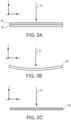
- FIGS. 3A-3C are cross-sectional views of layers in an optical system for displaying a virtual image, according to an embodiment of the present description. These figures illustrate what is meant by "normally incident light” as discussed in terms of each of the layers discussed herein.
- FIG. 3A shows normally incident light 50 in relation to first reflective polarizer 30 and second reflective polarizer 40.
- FIG. 3B shows normally incident light 51 in relation to mirror 90.
- mirror 90 may be curved to provide power (e.g., magnification) of the reflected image rays, as shown in FIG. 3B .
- normally incident light 51 is defined as orthogonal to a center point of mirror 90. As any of the components shown in FIGS.
- normally incident light shall be defined relative to incidence on a center point of the components (e.g., the reflective polarizers 30/40 of FIG. 3A , the absorbing polarizer 110 of FIG. 3C ).
- FIG. 3C shows normally incident light 52 in relation to absorbing polarizer 110.
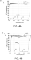
- FIG. 4A-4B provide graphs illustrating percentage transmittance of various wavelengths of light for each of the first 30 and second reflective polarizers 40, according to an embodiment of the present description, and FIG. 5 shows the combined transmission spectra of both reflective polarizers 30/40.
- FIG. 4A shows the percent transmission of wavelengths for first reflective polarizer 30.
- FIG. 4A depicts two lines, one representing light polarized in a first polarization state, and the other representing light polarized in a second polarization state.
- the films are configured such that the x-axis of the film is aligned with the first polarization state, and the y-axis of the film is aligned with the second polarization state.
- alternate embodiments are possible within the scope of this disclosure which use different configurations of the films, with alternate alignments and polarization states.
- the first reflective polarizer 30 transmits a significant portion (i.e., over 80 percent for much of the plot) of the light polarized to the y-axis of the film (e.g., the second polarization state of light) for both human-visible wavelengths (e.g., about 450 nm to about 680 nm) and infrared wavelengths (e.g., about 900 nm to about 1150 nm).
- human-visible wavelengths e.g., about 450 nm to about 680 nm
- infrared wavelengths e.g., about 900 nm to about 1150 nm.
- the first reflective polarizer 30 reflects (i.e., does not transmit) a significant portion (i.e., over 95 percent for much of the plot) of the light polarized to the x-axis (e.g., the first polarization of light) for both human-visible wavelengths (e.g., about 450 nm to about 680 nm) and infrared wavelengths (e.g., about 900 nm to about 1150 nm).
- human-visible wavelengths e.g., about 450 nm to about 680 nm
- infrared wavelengths e.g., about 900 nm to about 1150 nm.
- a representative human-visible wavelength 61 and infrared wavelength 71 are shown for illustration purposes.
- FIG. 4B shows the percent transmission of wavelengths for second reflective polarizer 40.
- FIG. 4B also depicts two lines, one representing light polarized in a first polarization state (e.g., polarized to the x-axis), and the other representing light polarized in a second polarization state (e.g., polarized to the y-axis).
- the second reflective polarizer 40 transmits a significant portion (i.e., over 80 percent for much of the plot) of the light polarized to the y-axis for human-visible wavelengths from about 450 nm to about 680 nm, but reflects (e.g., does not transmit) infrared wavelengths from about 850 nm to about 1150 nm.
- the second reflective polarizer 40 largely transmits a significant portion (i.e., over 80 percent for much of the plot) of the light polarized to the x-axis for both human-visible wavelengths (e.g., about 450 nm to about 680 nm) and infrared wavelengths (e.g., about 900 nm to about 1150 nm).
- human-visible wavelengths e.g., about 450 nm to about 680 nm
- infrared wavelengths e.g., about 900 nm to about 1150 nm.
- representative human-visible wavelength 61 and infrared wavelength 71 are shown for illustration and comparison purposes.
- FIG. 5 shows the percent transmittance for an optical stack with both first reflective polarizer 30 and second reflective polarizer 40 included.
- the combined reflective polarizers 30/40 transmit a significant portion (i.e., over 70 percent for much of the plot) of the light polarized to the y-axis for human-visible wavelengths from about 450 nm to about 680 nm, including representative human-visible wavelength 61, but substantially reflect (e.g., do not transmit) infrared wavelengths from about 850 nm to about 1150 nm, including representative infrared wavelength 71.
- the combined reflective polarizers 30/40 substantially reflect (e.g., do not transmit) human-visible wavelengths from about 450 nm to about 680 nm and infrared wavelengths from about 850 nm to about 1150 nm.
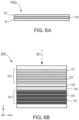
- FIGS. 6A-6B show cross-sectional views of an optical stack according to an embodiment of the present disclosure, including additional details on the possible construction of the layers.
- FIG. 6A illustrates that, in some embodiments, the first reflective polarizer 30 and the second reflective polarizer 40 may be bonded to each other by an optical adhesive layer 100.
- an optical adhesive layer 100 is a curable acrylate adhesive. However, any appropriate type of optical adhesive layer 100 may be used.
- FIG. 6B illustrates an optical film 300 comprising an integral first optical stack 330 disposed on an integral second optical stack 340.
- first optical stack 330 may be the first reflective polarizer 30 of FIG. 1
- second optical stack 340 may be the second reflective polarizer 40 of FIG. 1 .
- integral first optical stack 330 may include a plurality of alternating polymeric interference layers 331 and 332, which reflect and transmit light primarily by optical interference (e.g., alternating layers 331 and 332 may have different indices of refraction), and integral second optical stack 340 may include a plurality of alternating polymeric interference layers 341 and 342, which also reflect and transmit light primarily by optical interference.
- polymeric interference layers 331 and 332 may be configured such that, for at least one visible wavelength in a first wavelength range extending from about 450 nm to about 680 nm (e.g., human-visible wavelengths), and at least one infrared wavelength in a second wavelength range extending from about 900 nm to about 1150 nm (e.g., infrared wavelengths), for substantially normally incident light 301, the integral first optical stack 330 reflects at least 70%, or at least 75%, or at least 80% of the incident light having a first polarization state (x-axis) and transmits at least 70%, or at least 75%, or at least 80% of the incident light having an orthogonal second polarization state (y-axis).
- polymeric interference layers 341 and 342 may be configured such that, for at least one visible wavelength in a first wavelength range extending from about 450 nm to about 680 nm (e.g., human-visible wavelengths), for substantially normally incident light 301, the second optical stack 340 transmits at least 70%, or at least 75%, or at least 80% of the incident light for each of the first and second polarization states, and for the at least one infrared wavelength, the second optical stack 340 reflects at least 60%, or at least 65%, or at least 70% of the incident light having the first polarization state and transmits at least 60%, or at least 65%, or at least 70% of the incident light having the second polarization state.
- a first wavelength range extending from about 450 nm to about 680 nm (e.g., human-visible wavelengths)
- the second optical stack 340 transmits at least 70%, or at least 75%, or at least 80% of the incident light for each of the first and second polarization states, and for
- first optical stack 330 may be spaced apart from the second optical stack 340 by one or more spacers 320.
- the average thickness of each of spacer layers may be at least 5 times greater than the average thickness of each polymeric interference layer (331, 332, 341, 342) in each optical stack 330 and 340.
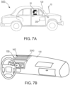
- FIGS. 7A-7C show alternate views of an optical system for displaying a virtual image as installed in a vehicle, according to an embodiment of the present description.
- transmitted image 82 passes through optical system 200 to be reflected from windshield 120 of vehicle 500 into the eyes of passenger 20, creating the perception of virtual image 10 outside of vehicle 500.
- FIG. 7B shows additional detail of the interior of the vehicle 500 (of FIG. 7A ).
- the first reflective polarizer 30 and second reflective polarizer 40 may be disposed on an exit surface 150 of dashboard 130, for example a glare trap 142.
- Glare trap 142 may be disposed on the exit surface 150 for a heads-up display, configured to reduce or prevent ambient light (e.g., sunlight) from passing into the heads-up display.
- glare trap 142 on exit surface 150 may further include an infrared absorbing dye 148, such that the glare trap may absorb some portion (e.g., at least 20%) of an incident light having a wavelength from about 800 nm to about 2000 nm, where absorbing dye 148 may be included in a layer designed primarily to absorb light, or added to another layer having other optical properties.
- an infrared absorbing dye 148 such that the glare trap may absorb some portion (e.g., at least 20%) of an incident light having a wavelength from about 800 nm to about 2000 nm, where absorbing dye 148 may be included in a layer designed primarily to absorb light, or added to another layer having other optical properties.
- FIG. 8 show an optical film for use in an optical system for displaying a virtual image, as part of a web, according to an embodiment of the present description.
- the optical film 300 (see FIG. 6B ) may be cut from a longitudinally continuous web 350, wherein the y-axis is along a longitudinal down-web direction 351 and the x-axis is along a lateral cross-web direction 352.
- the orientation of the optical film 300 in relation to longitudinally continuous web 350 defines the optical properties of the optical film 300 with regard to polarization states of light as discussed herein.
- substantially aligned will mean aligned to within 20% of a width of the objects being aligned.
- Objects described as substantially aligned may, in some embodiments, be aligned to within 10% or to within 5% of a width of the objects being aligned.
Landscapes
- Physics & Mathematics (AREA)
- General Physics & Mathematics (AREA)
- Optics & Photonics (AREA)
- Spectroscopy & Molecular Physics (AREA)
- Polarising Elements (AREA)
- Instrument Panels (AREA)
Claims (15)
- Ein optisches System (400) zum Anzeigen eines virtuellen Bildes für einen Betrachter (20), aufweisend:
einen gestapelten einstückigen ersten Reflexionspolarisator (30) und einen einstückigen zweiten Reflexionspolarisator (40), derart für im Wesentlichen senkrecht einfallendes Licht:für mindestens eine sichtbare Wellenlänge in einem ersten Wellenlängenbereich, der sich von etwa 450 nm bis etwa 680 nm erstreckt, reflektiert der erste Reflexionspolarisator mindestens 60 % des einfallenden Lichts, das über einen ersten Polarisationszustand verfügt, und lässt mindestens 60 % des einfallenden Lichts, das über einen orthogonalen zweiten Polarisationszustand verfügt, durch, und der zweite Reflexionspolarisator lässt mindestens 60 % des einfallenden Lichts für jeden des ersten und des zweiten Polarisationszustands durch; undfür mindestens eine Infrarotwellenlänge in einem zweiten Wellenlängenbereich, der sich von etwa 900 nm bis etwa 1150 nm erstreckt, reflektiert der erste Reflexionspolarisator mindestens 60 % des einfallenden Lichts, das über den ersten Polarisationszustand verfügt, und lässt mindestens 60 % des einfallenden Lichts, das über den zweiten Polarisationszustand verfügt, durch, und der zweite Reflexionspolarisator reflektiert mindestens 60 % des einfallenden Lichts, das über den zweiten Polarisationszustand verfügt, und lässt mindestens 20 % des Lichts, das über den ersten Polarisationszustand verfügt, durch; undeine Anzeige (80) und einen Spiegel (90), die auf einerselben Seite davon angeordnet sind und im Allgemeinen dem gestapelten ersten und zweiten Reflexionspolarisator zugewandt sind, derart, dass für im Wesentlichen senkrecht einfallendes Licht und für die mindestens eine sichtbare Wellenlänge der Spiegel mindestens 80 % des einfallenden Lichts für jeden des ersten und des zweiten Polarisationszustands reflektiert, und derart, dass, wenn ein Bild (81) durch die Anzeige ausgestrahlt wird, das optische System ein virtuelles Bild des ausgestrahlten Bildes, nachdem das ausgestrahlte Bild mindestens einmal durch den gestapelten ersten und zweiten Reflexionspolarisator reflektiert wird, zum Betrachten durch einen Betrachter anzeigt. - Das optische System nach Anspruch 1, wobei die mindestens eine sichtbare Wellenlänge eine oder mehrere von einer blauen Wellenlänge, einer grünen Wellenlänge und einer roten Wellenlänge aufweist.
- Das optische System nach Anspruch 1, wobei für das im Wesentlichen senkrecht einfallende Licht und die mindestens eine sichtbare Wellenlänge der erste Reflexionspolarisator mindestens 70 % des einfallenden Lichts, das über den ersten Polarisationszustand verfügt, reflektiert und mindestens 70 % des einfallenden Lichts, das über den zweiten Polarisationszustand verfügt, durchlässt, und der zweite Reflexionspolarisator mindestens 70 % des einfallenden Lichts für jeden des ersten und des zweiten Polarisationszustands durchlässt.
- Das optische System nach Anspruch 1, wobei die mindestens eine Infrarotwellenlänge mindestens eine Infrarotwellenlänge, die durch die Sonne ausgestrahlt wird, aufweist.
- Das optische System nach Anspruch 1, wobei für das im Wesentlichen senkrecht einfallende Licht und die mindestens eine Infrarotwellenlänge der erste Reflexionspolarisator mindestens 70 % des einfallenden Lichts, das über den ersten Polarisationszustand verfügt, reflektiert und mindestens 70 % des einfallenden Lichts, das über den zweiten Polarisationszustand verfügt, durchlässt, und der zweite Reflexionspolarisator mindestens 70 % des einfallenden Lichts, das über den zweiten Polarisationszustand verfügt, reflektiert und mindestens 30 % des Lichts, das über den ersten Polarisationszustand verfügt, durchlässt.
- Das optische System nach Anspruch 1, wobei für im Wesentlichen senkrecht einfallendes Licht und für die mindestens eine Wellenlänge im Infrarotwellenlängenbereich der zweite Reflexionspolarisator mindestens 60 % des einfallenden Lichts, das über den ersten Polarisationszustand verfügt, reflektiert.
- Das optische System nach Anspruch 1, wobei die Anzeige eine oder mehrere von einer Leuchtdiodenanzeige, einer organischen Leuchtdiodenanzeige, einer Flüssigkristallanzeige und einer Elektrolumineszenzanzeige aufweist.
- Das optische System nach Anspruch 1, wobei für im Wesentlichen senkrecht einfallendes Licht und für die mindestens eine sichtbare Wellenlänge der Spiegel mindestens 90 % des einfallenden Lichts für jeden des ersten und des zweiten Polarisationszustands reflektiert.
- Das optische System nach Anspruch 1, wobei der erste Reflexionspolarisator zwischen dem zweiten Reflexionspolarisator und dem Spiegel angeordnet ist.
- Das optische System nach Anspruch 1, wobei, wenn ein Bild durch die Anzeige ausgestrahlt wird, ein sichtbarer Bildstrahl von dem ausgestrahlten Bild nacheinander durch den ersten Reflexionspolarisator reflektiert wird, durch den Spiegel reflektiert wird und durch den gestapelten ersten und zweiten Reflexionspolarisator durchgelassen wird, wodurch ein virtuelles Bild der durchgelassenen Bildanzeige zum Betrachten durch den Betrachter erzeugt wird.
- Das optische System nach Anspruch 1, ferner aufweisend einen Absorptionspolarisator (110), der auf dem gestapelten ersten und zweiten Reflexionspolarisator angeordnet ist, wobei der gestapelte erste und zweite Reflexionspolarisator zwischen dem Absorptionspolarisator und dem Spiegel angeordnet sind, und wobei für im Wesentlichen senkrecht einfallendes Licht und für die mindestens eine sichtbare Wellenlänge der Absorptionspolarisator mindestens 60 % des einfallenden Lichts, das über den ersten Polarisationszustand verfügt, absorbiert und mindestens 60 % des einfallenden Lichts, das über den zweiten Polarisationszustand verfügt, durchlässt.
- Eine Head-up-Anzeige, aufweisend:das optische System nach Anspruch 1; undeine Windschutzscheibe (120) eines Fahrzeugs, derart, dass, wenn ein Bild durch die Anzeige ausgestrahlt wird, das optische System das ausgestrahlte Bild in Richtung der Windschutzscheibe überträgt, die Windschutzscheibe das übertragene Bild in Richtung eines Betrachters in dem Fahrzeug reflektiert, wobei der Betrachter ein virtuelles Bild des ausgestrahlten Bildes betrachtet.
- Ein Fahrzeug, aufweisend das optische System nach Anspruch 1.
- Das Fahrzeug nach Anspruch 13, wobei der gestapelte erste und zweite Reflexionspolarisator an oder in einer Nähe eines Armaturenbretts des Fahrzeugs angeordnet sind.
- Eine optischer Folie (300), aufweisend einen einstückigen ersten optischen Stapel (330), der auf einem einstückigen zweiten optischen Stapel, Stapel (340) angeordnet ist, jeder einstückige optische Stapel aufweisend eine Vielzahl von polymeren Interferenzschichten (331, 332, 341, 342), die Licht hauptsächlich durch optische Interferenz für mindestens eine sichtbare Wellenlänge in einem ersten Wellenlängenbereich, der sich von etwa 450 nm bis etwa 680 nm erstreckt, und mindestens eine Infrarotwellenlänge in einem zweiten Wellenlängenbereich, der sich von etwa 900 nm bis etwa 1150 nm erstreckt, reflektieren und durchlassen, derart für im Wesentlichen senkrecht einfallendes Licht:für die mindestens eine sichtbare Wellenlänge reflektiert der einstückige erste optische Stapel mindestens 70 % des einfallenden Lichts, das über einen ersten Polarisationszustand verfügt und lässt mindestens 70 % des einfallenden Lichts, das über einen orthogonalen zweiten Polarisationszustand verfügt, durch, und der zweite optische Stapel lässt mindestens 70 % des einfallenden Lichts für jeden des ersten und des zweiten Polarisationszustands durch; undfür die mindestens eine Infrarotwellenlänge reflektiert der zweite optische Stapel mindestens 60 % des einfallenden Lichts, das über den ersten Polarisationszustand verfügt, und lässt mindestens 60 % des einfallenden Lichts, das über den zweiten Polarisationszustand verfügt, durch.
Applications Claiming Priority (2)
| Application Number | Priority Date | Filing Date | Title |
|---|---|---|---|
| US202062968240P | 2020-01-31 | 2020-01-31 | |
| PCT/IB2021/050641 WO2021152480A1 (en) | 2020-01-31 | 2021-01-27 | Polarization beam splitter and hot mirror for heads up display |
Publications (2)
| Publication Number | Publication Date |
|---|---|
| EP4097516A1 EP4097516A1 (de) | 2022-12-07 |
| EP4097516B1 true EP4097516B1 (de) | 2025-06-04 |
Family
ID=74505299
Family Applications (1)
| Application Number | Title | Priority Date | Filing Date |
|---|---|---|---|
| EP21703062.6A Active EP4097516B1 (de) | 2020-01-31 | 2021-01-27 | Polarisationsstrahlteiler und heissspiegel für head-up-anzeige |
Country Status (4)
| Country | Link |
|---|---|
| US (2) | US11740480B2 (de) |
| EP (1) | EP4097516B1 (de) |
| JP (1) | JP2023506582A (de) |
| WO (1) | WO2021152480A1 (de) |
Families Citing this family (4)
| Publication number | Priority date | Publication date | Assignee | Title |
|---|---|---|---|---|
| US12181666B2 (en) * | 2020-05-25 | 2024-12-31 | Samsung Electronics Co., Ltd. | System of virtual image projection on screen with effect of eliminating influence of solar radiation |
| US20240302655A1 (en) * | 2023-03-09 | 2024-09-12 | Panasonic Automotive Systems Company Of America, Division Of Panasonic Corporation Of North America | Heads up display glare trap reflection solution |
| WO2024232334A1 (ja) * | 2023-05-09 | 2024-11-14 | 富士フイルム株式会社 | プロジェクターおよびヘッドアップディスプレイシステム |
| WO2025191384A1 (en) * | 2024-03-13 | 2025-09-18 | 3M Innovative Properties Company | Compact folded optical system for heads-up display |
Family Cites Families (19)
| Publication number | Priority date | Publication date | Assignee | Title |
|---|---|---|---|---|
| JPH0756110A (ja) * | 1993-08-18 | 1995-03-03 | Toshiba Corp | ヘッドアップディスプレイ方法及びその装置 |
| US7826009B2 (en) * | 2006-12-21 | 2010-11-02 | 3M Innovative Properties Company | Hybrid polarizer |
| DE102011014145A1 (de) * | 2010-12-23 | 2012-06-28 | Continental Automotive Gmbh | Head-up-Display für ein Kraftfahrzeug |
| US9958699B2 (en) * | 2012-12-21 | 2018-05-01 | 3M Innovative Properties Company | Hybrid polarizing beam splitter |
| EP3072004A1 (de) * | 2013-11-19 | 2016-09-28 | 3M Innovative Properties Company | Durchsichtiges kopfmontiertes display mit einem flüssigkristallmodul zur einstellung des helligkeitsverhältnisses kombinierter bilder |
| JP6247952B2 (ja) | 2014-02-13 | 2017-12-13 | 株式会社 オルタステクノロジー | ヘッドアップディスプレイ装置 |
| CN204687853U (zh) | 2015-03-20 | 2015-10-07 | 京东方科技集团股份有限公司 | 一种车载显示系统和汽车 |
| US11422365B2 (en) * | 2017-02-23 | 2022-08-23 | Lg Electronics Inc. | Head up display for vehicle |
| KR102648211B1 (ko) * | 2017-03-06 | 2024-03-14 | 쓰리엠 이노베이티브 프로퍼티즈 컴파니 | 고 콘트라스트 광학 필름 및 이를 포함하는 장치 |
| JP2019028373A (ja) * | 2017-08-02 | 2019-02-21 | スリーエム イノベイティブ プロパティズ カンパニー | 表示装置、及び赤外光カットフィルム |
| US10788667B2 (en) * | 2017-08-31 | 2020-09-29 | Vitro Flat Glass Llc | Heads-up display and coating therefor |
| US11921287B2 (en) * | 2017-09-04 | 2024-03-05 | Maxell, Ltd. | Information display apparatus |
| WO2019077547A1 (en) | 2017-10-20 | 2019-04-25 | 3M Innovative Properties Company | OPTICAL FILM AND POLARIZING BEAM SEPARATOR |
| US11493777B2 (en) * | 2017-12-20 | 2022-11-08 | 3M Innovative Properties Company | Optical stack and polarizing beam splitter |
| JP7466516B2 (ja) * | 2018-07-13 | 2024-04-12 | スリーエム イノベイティブ プロパティズ カンパニー | 光学システム及び光学フィルム |
| JP7539383B2 (ja) * | 2018-12-21 | 2024-08-23 | スリーエム イノベイティブ プロパティズ カンパニー | 小型ヘッドアップディスプレイ |
| CN114616507A (zh) * | 2019-06-06 | 2022-06-10 | 3M创新有限公司 | 紧凑型平视显示器 |
| WO2021056372A1 (en) * | 2019-09-27 | 2021-04-01 | 3M Innovative Properties Company | Reflective polarizer and optical system |
| WO2021130580A1 (en) * | 2019-12-23 | 2021-07-01 | 3M Innovative Properties Company | Optical stack and display |
-
2021
- 2021-01-27 EP EP21703062.6A patent/EP4097516B1/de active Active
- 2021-01-27 WO PCT/IB2021/050641 patent/WO2021152480A1/en not_active Ceased
- 2021-01-27 JP JP2022546375A patent/JP2023506582A/ja active Pending
- 2021-01-27 US US17/795,065 patent/US11740480B2/en active Active
-
2023
- 2023-07-12 US US18/220,934 patent/US12092838B2/en active Active
Also Published As
| Publication number | Publication date |
|---|---|
| JP2023506582A (ja) | 2023-02-16 |
| US12092838B2 (en) | 2024-09-17 |
| US11740480B2 (en) | 2023-08-29 |
| WO2021152480A1 (en) | 2021-08-05 |
| EP4097516A1 (de) | 2022-12-07 |
| US20230350217A1 (en) | 2023-11-02 |
| US20230085544A1 (en) | 2023-03-16 |
Similar Documents
| Publication | Publication Date | Title |
|---|---|---|
| US12092838B2 (en) | Polarization beam splitter and hot mirror for heads up display | |
| US6952312B2 (en) | Head-up display with polarized light source and wide-angle p-polarization reflective polarizer | |
| JP2021534452A (ja) | 光学システム | |
| WO2020068513A1 (en) | Glass laminate including reflective film | |
| CN114077052A (zh) | 多层图像显示装置、抬头显示器以及交通设备 | |
| WO2015177833A1 (ja) | 虚像生成素子及びヘッドアップディスプレイ | |
| US12554130B2 (en) | Compact heads-up display | |
| CN218213623U (zh) | 显示装置、抬头显示器以及交通设备 | |
| JP7785067B2 (ja) | ヘッドアップディスプレイシステム | |
| US12287481B2 (en) | Optical system | |
| US12066636B2 (en) | Polarization optimized heads-up display | |
| US20250189784A1 (en) | Folded optical system optimized to mitigate glare | |
| US12269339B2 (en) | Heads up display | |
| US12351024B2 (en) | Display system for vehicle | |
| JPWO2021099905A5 (de) | ||
| US20230384500A1 (en) | Ultraviolet-stable optical films | |
| US20230393410A1 (en) | Display system for vehicle | |
| HK1087181A (en) | Head-up display with polarized light source and wide-angle p-polarization reflective polarizer |
Legal Events
| Date | Code | Title | Description |
|---|---|---|---|
| STAA | Information on the status of an ep patent application or granted ep patent |
Free format text: STATUS: UNKNOWN |
|
| STAA | Information on the status of an ep patent application or granted ep patent |
Free format text: STATUS: THE INTERNATIONAL PUBLICATION HAS BEEN MADE |
|
| PUAI | Public reference made under article 153(3) epc to a published international application that has entered the european phase |
Free format text: ORIGINAL CODE: 0009012 |
|
| STAA | Information on the status of an ep patent application or granted ep patent |
Free format text: STATUS: REQUEST FOR EXAMINATION WAS MADE |
|
| 17P | Request for examination filed |
Effective date: 20220725 |
|
| AK | Designated contracting states |
Kind code of ref document: A1 Designated state(s): AL AT BE BG CH CY CZ DE DK EE ES FI FR GB GR HR HU IE IS IT LI LT LU LV MC MK MT NL NO PL PT RO RS SE SI SK SM TR |
|
| DAV | Request for validation of the european patent (deleted) | ||
| DAX | Request for extension of the european patent (deleted) | ||
| GRAP | Despatch of communication of intention to grant a patent |
Free format text: ORIGINAL CODE: EPIDOSNIGR1 |
|
| STAA | Information on the status of an ep patent application or granted ep patent |
Free format text: STATUS: GRANT OF PATENT IS INTENDED |
|
| INTG | Intention to grant announced |
Effective date: 20250102 |
|
| P01 | Opt-out of the competence of the unified patent court (upc) registered |
Free format text: CASE NUMBER: APP_4086/2025 Effective date: 20250122 |
|
| GRAS | Grant fee paid |
Free format text: ORIGINAL CODE: EPIDOSNIGR3 |
|
| GRAA | (expected) grant |
Free format text: ORIGINAL CODE: 0009210 |
|
| STAA | Information on the status of an ep patent application or granted ep patent |
Free format text: STATUS: THE PATENT HAS BEEN GRANTED |
|
| AK | Designated contracting states |
Kind code of ref document: B1 Designated state(s): AL AT BE BG CH CY CZ DE DK EE ES FI FR GB GR HR HU IE IS IT LI LT LU LV MC MK MT NL NO PL PT RO RS SE SI SK SM TR |
|
| REG | Reference to a national code |
Ref country code: GB Ref legal event code: FG4D |
|
| REG | Reference to a national code |
Ref country code: CH Ref legal event code: EP |
|
| REG | Reference to a national code |
Ref country code: DE Ref legal event code: R096 Ref document number: 602021031721 Country of ref document: DE |
|
| REG | Reference to a national code |
Ref country code: IE Ref legal event code: FG4D |
|
| REG | Reference to a national code |
Ref country code: NL Ref legal event code: MP Effective date: 20250604 |
|
| PG25 | Lapsed in a contracting state [announced via postgrant information from national office to epo] |
Ref country code: FI Free format text: LAPSE BECAUSE OF FAILURE TO SUBMIT A TRANSLATION OF THE DESCRIPTION OR TO PAY THE FEE WITHIN THE PRESCRIBED TIME-LIMIT Effective date: 20250604 Ref country code: ES Free format text: LAPSE BECAUSE OF FAILURE TO SUBMIT A TRANSLATION OF THE DESCRIPTION OR TO PAY THE FEE WITHIN THE PRESCRIBED TIME-LIMIT Effective date: 20250604 |
|
| REG | Reference to a national code |
Ref country code: LT Ref legal event code: MG9D |
|
| PG25 | Lapsed in a contracting state [announced via postgrant information from national office to epo] |
Ref country code: GR Free format text: LAPSE BECAUSE OF FAILURE TO SUBMIT A TRANSLATION OF THE DESCRIPTION OR TO PAY THE FEE WITHIN THE PRESCRIBED TIME-LIMIT Effective date: 20250905 Ref country code: NO Free format text: LAPSE BECAUSE OF FAILURE TO SUBMIT A TRANSLATION OF THE DESCRIPTION OR TO PAY THE FEE WITHIN THE PRESCRIBED TIME-LIMIT Effective date: 20250904 |
|
| PG25 | Lapsed in a contracting state [announced via postgrant information from national office to epo] |
Ref country code: PL Free format text: LAPSE BECAUSE OF FAILURE TO SUBMIT A TRANSLATION OF THE DESCRIPTION OR TO PAY THE FEE WITHIN THE PRESCRIBED TIME-LIMIT Effective date: 20250604 |
|
| PG25 | Lapsed in a contracting state [announced via postgrant information from national office to epo] |
Ref country code: BG Free format text: LAPSE BECAUSE OF FAILURE TO SUBMIT A TRANSLATION OF THE DESCRIPTION OR TO PAY THE FEE WITHIN THE PRESCRIBED TIME-LIMIT Effective date: 20250604 |
|
| PG25 | Lapsed in a contracting state [announced via postgrant information from national office to epo] |
Ref country code: HR Free format text: LAPSE BECAUSE OF FAILURE TO SUBMIT A TRANSLATION OF THE DESCRIPTION OR TO PAY THE FEE WITHIN THE PRESCRIBED TIME-LIMIT Effective date: 20250604 |
|
| PG25 | Lapsed in a contracting state [announced via postgrant information from national office to epo] |
Ref country code: RS Free format text: LAPSE BECAUSE OF FAILURE TO SUBMIT A TRANSLATION OF THE DESCRIPTION OR TO PAY THE FEE WITHIN THE PRESCRIBED TIME-LIMIT Effective date: 20250904 |
|
| PG25 | Lapsed in a contracting state [announced via postgrant information from national office to epo] |
Ref country code: LV Free format text: LAPSE BECAUSE OF FAILURE TO SUBMIT A TRANSLATION OF THE DESCRIPTION OR TO PAY THE FEE WITHIN THE PRESCRIBED TIME-LIMIT Effective date: 20250604 |
|
| PG25 | Lapsed in a contracting state [announced via postgrant information from national office to epo] |
Ref country code: NL Free format text: LAPSE BECAUSE OF FAILURE TO SUBMIT A TRANSLATION OF THE DESCRIPTION OR TO PAY THE FEE WITHIN THE PRESCRIBED TIME-LIMIT Effective date: 20250604 |
|
| PG25 | Lapsed in a contracting state [announced via postgrant information from national office to epo] |
Ref country code: PT Free format text: LAPSE BECAUSE OF FAILURE TO SUBMIT A TRANSLATION OF THE DESCRIPTION OR TO PAY THE FEE WITHIN THE PRESCRIBED TIME-LIMIT Effective date: 20251006 |
|
| REG | Reference to a national code |
Ref country code: AT Ref legal event code: MK05 Ref document number: 1800852 Country of ref document: AT Kind code of ref document: T Effective date: 20250604 |
|
| PG25 | Lapsed in a contracting state [announced via postgrant information from national office to epo] |
Ref country code: IS Free format text: LAPSE BECAUSE OF FAILURE TO SUBMIT A TRANSLATION OF THE DESCRIPTION OR TO PAY THE FEE WITHIN THE PRESCRIBED TIME-LIMIT Effective date: 20251004 |
|
| PG25 | Lapsed in a contracting state [announced via postgrant information from national office to epo] |
Ref country code: AT Free format text: LAPSE BECAUSE OF FAILURE TO SUBMIT A TRANSLATION OF THE DESCRIPTION OR TO PAY THE FEE WITHIN THE PRESCRIBED TIME-LIMIT Effective date: 20250604 Ref country code: SM Free format text: LAPSE BECAUSE OF FAILURE TO SUBMIT A TRANSLATION OF THE DESCRIPTION OR TO PAY THE FEE WITHIN THE PRESCRIBED TIME-LIMIT Effective date: 20250604 |
|
| PG25 | Lapsed in a contracting state [announced via postgrant information from national office to epo] |
Ref country code: CZ Free format text: LAPSE BECAUSE OF FAILURE TO SUBMIT A TRANSLATION OF THE DESCRIPTION OR TO PAY THE FEE WITHIN THE PRESCRIBED TIME-LIMIT Effective date: 20250604 |
|
| PG25 | Lapsed in a contracting state [announced via postgrant information from national office to epo] |
Ref country code: EE Free format text: LAPSE BECAUSE OF FAILURE TO SUBMIT A TRANSLATION OF THE DESCRIPTION OR TO PAY THE FEE WITHIN THE PRESCRIBED TIME-LIMIT Effective date: 20250604 |
|
| PG25 | Lapsed in a contracting state [announced via postgrant information from national office to epo] |
Ref country code: SK Free format text: LAPSE BECAUSE OF FAILURE TO SUBMIT A TRANSLATION OF THE DESCRIPTION OR TO PAY THE FEE WITHIN THE PRESCRIBED TIME-LIMIT Effective date: 20250604 |
|
| PG25 | Lapsed in a contracting state [announced via postgrant information from national office to epo] |
Ref country code: IT Free format text: LAPSE BECAUSE OF FAILURE TO SUBMIT A TRANSLATION OF THE DESCRIPTION OR TO PAY THE FEE WITHIN THE PRESCRIBED TIME-LIMIT Effective date: 20250604 |