EP4096464B1 - Schuhsohlenstruktur mit verschachteltem schaumkern - Google Patents
Schuhsohlenstruktur mit verschachteltem schaumkern Download PDFInfo
- Publication number
- EP4096464B1 EP4096464B1 EP21711421.4A EP21711421A EP4096464B1 EP 4096464 B1 EP4096464 B1 EP 4096464B1 EP 21711421 A EP21711421 A EP 21711421A EP 4096464 B1 EP4096464 B1 EP 4096464B1
- Authority
- EP
- European Patent Office
- Prior art keywords
- foam core
- sole structure
- sole
- leg
- component
- Prior art date
- Legal status (The legal status is an assumption and is not a legal conclusion. Google has not performed a legal analysis and makes no representation as to the accuracy of the status listed.)
- Active
Links
Images


Classifications
-
- A—HUMAN NECESSITIES
- A43—FOOTWEAR
- A43B—CHARACTERISTIC FEATURES OF FOOTWEAR; PARTS OF FOOTWEAR
- A43B13/00—Soles; Sole-and-heel integral units
- A43B13/14—Soles; Sole-and-heel integral units characterised by the constructive form
- A43B13/16—Pieced soles
-
- A—HUMAN NECESSITIES
- A43—FOOTWEAR
- A43B—CHARACTERISTIC FEATURES OF FOOTWEAR; PARTS OF FOOTWEAR
- A43B13/00—Soles; Sole-and-heel integral units
- A43B13/02—Soles; Sole-and-heel integral units characterised by the material
- A43B13/12—Soles with several layers of different materials
- A43B13/122—Soles with several layers of different materials characterised by the outsole or external layer
-
- A—HUMAN NECESSITIES
- A43—FOOTWEAR
- A43B—CHARACTERISTIC FEATURES OF FOOTWEAR; PARTS OF FOOTWEAR
- A43B13/00—Soles; Sole-and-heel integral units
- A43B13/02—Soles; Sole-and-heel integral units characterised by the material
- A43B13/12—Soles with several layers of different materials
- A43B13/125—Soles with several layers of different materials characterised by the midsole or middle layer
-
- A—HUMAN NECESSITIES
- A43—FOOTWEAR
- A43B—CHARACTERISTIC FEATURES OF FOOTWEAR; PARTS OF FOOTWEAR
- A43B13/00—Soles; Sole-and-heel integral units
- A43B13/14—Soles; Sole-and-heel integral units characterised by the constructive form
- A43B13/18—Resilient soles
- A43B13/181—Resiliency achieved by the structure of the sole
- A43B13/185—Elasticated plates sandwiched between two interlocking components, e.g. thrustors
-
- A—HUMAN NECESSITIES
- A43—FOOTWEAR
- A43B—CHARACTERISTIC FEATURES OF FOOTWEAR; PARTS OF FOOTWEAR
- A43B13/00—Soles; Sole-and-heel integral units
- A43B13/14—Soles; Sole-and-heel integral units characterised by the constructive form
- A43B13/18—Resilient soles
- A43B13/187—Resiliency achieved by the features of the material, e.g. foam, non liquid materials
- A43B13/188—Differential cushioning regions
-
- A—HUMAN NECESSITIES
- A43—FOOTWEAR
- A43B—CHARACTERISTIC FEATURES OF FOOTWEAR; PARTS OF FOOTWEAR
- A43B13/00—Soles; Sole-and-heel integral units
- A43B13/02—Soles; Sole-and-heel integral units characterised by the material
- A43B13/04—Plastics, rubber or vulcanised fibre
-
- A—HUMAN NECESSITIES
- A43—FOOTWEAR
- A43B—CHARACTERISTIC FEATURES OF FOOTWEAR; PARTS OF FOOTWEAR
- A43B13/00—Soles; Sole-and-heel integral units
- A43B13/28—Soles; Sole-and-heel integral units characterised by their attachment, also attachment of combined soles and heels
- A43B13/32—Soles; Sole-and-heel integral units characterised by their attachment, also attachment of combined soles and heels by adhesives
Definitions
- the present disclosure generally relates to a sole structure for an article of footwear that includes a form core nested in sole component.
- the present disclosure generally relates to a sole structure for an article of footwear.
- the sole structure has a foam core with relatively high energy return and cushioning ability and is configured and constructed to protect the foam core from wear while minimizing constraint of the foam core so that its cushioning advantages may be more fully realized.
- the second portion of the side surface may be free from any attachment within the space.
- the foam core is sufficiently secured to the sole component to ensure stability of the sole structure while still allowing a portion of the foam core to resiliently deform at least under an initial stage of loading without interference from or constraint by the sole component.
- the bottom wall of the sole component may have a through hole and the foam core may extend over the through hole. Accordingly, some freedom of movement of the foam core during compression is afforded at the bottom of the foam core as well.
- the sole structure may further comprise a midsole layer extending between a top surface of the sole component and a bottom surface of the foam core.
- the bottom surface of the foam core may be secured to a top surface of the midsole layer, and a bottom surface of the midsole layer may be secured to the top surface of the sole component.
- the foam core and the sole component may be disposed in a heel region of the sole structure, and the midsole layer may extend forward from between the foam core and the sole component in the heel region.
- the midsole layer may extend to a midfoot region and a forefoot region of the sole structure in addition to the heel region.
- the outsole component 18 may include a rubber material than may be a natural rubber, or a synthetic rubber, or a combination of both.
- types of rubbers include butadiene rubber, styrenebutadiene (SBR) rubber, butyl rubber, isoprene rubber, urethane rubber, nitrile rubber, neoprene rubber, ethylene propylene diene monomer (EPDM) rubber, ethylenepropylene rubber, urethane rubber, polynorbomene rubber, methyl methacrylate butadiene styrene (MBS) rubber, styrene ethylene butylene (SEBS) rubber, silicone rubber, and mixtures thereof.
- the rubber compound may be a virgin material, a regrind material, and mixtures thereof.
- the sole structure 10 includes a heel region 24, a midfoot region 26, and a forefoot region 28.
- the heel region 24 generally includes portions of the sole structure 10 corresponding with rear portions of a human foot 77, including the calcaneus bone, when the human foot of a size corresponding with the sole structure 10 is disposed in a foot-receiving cavity 30 of the article of footwear 12 and is supported on the sole structure 10 as shown in FIG. 5 .
- the forefoot region 28 of the sole structure 10 generally includes portions of the sole structure 10 corresponding with the toes and the joints connecting the metatarsals with the phalanges of the human foot (interchangeably referred to herein as the "metatarsal-phalangeal joints" or "MPJ" joints).
- the midfoot region 26 of the sole structure 10 is disposed between the heel region 24 and the forefoot region 28 and generally includes portions of the sole structure 10 corresponding with an arch area of the human foot, including the navicular joint.
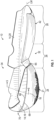
- the sole structure 10 has a medial side 32 (shown in FIG. 1 ) and a lateral side 34 (partially shown in FIG. 2 ) both of which extend from the heel region 24 to the forefoot region 28 and are generally on opposite sides of a longitudinal axis LM of the sole structure 10, which may be a longitudinal midline.
- the medial side 32, the lateral side 34, and a rear 70 of the sole structure 10 described herein correspond with and may also be used to indicate the medial side, the lateral side, and the rear of individual components of the sole structure 10.
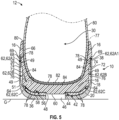
- the outsole component 18 has a bottom wall 36 that includes the ground-engaging surface 21 at the bottom of the sole structure 10.
- the outsole component 18 includes a peripheral wall 38 that extends upward from the bottom wall 36 and partially surrounds a space 40 above the bottom wall 36.
- a bottom surface 42 of the midsole layer 20 is disposed in the space 40 and bonded to or otherwise secured to a top surface 44 of the outsole component 18 in the space 40, such as with adhesive (adhesive layer 78 shown in FIG. 5 ).
- a through hole 46 in the outsole component 18 is aligned with a through hole 48 in the midsole layer 20.
- the foam core 16 is disposed in the space 40 with a bottom surface 56 of the foam core 16 secured to a top surface 58 of the midsole layer 20.
- the midsole layer 20 thus extends between the outsole component 18 and the bottom surface 56 of the foam core 16.
- a slight circular protrusion 60 in the bottom surface 56 may be aligned with the through holes 46 and 48.
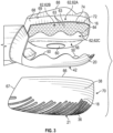
- the side surface 62 of the foam core 16 extends along the medial side 32, the lateral side 34, and the rear 70 of the sole structure 10.
- the peripheral wall 38 of the outsole component 18 extends adjacent to and outward of the side surface 62 of the foam core 16 at the medial side 32, the lateral side 34, and the rear 70 of the sole structure 10. Accordingly, the peripheral wall 38 effectively cups and protects the foam core 16 at the medial side 32, the lateral side 34, and the rear 70 of the foam core 16.
- the second portion 62B may have a textured surface as indicated by a plurality of rounded protrusions 63 (some indicated with reference numbers in FIGS. 3 , 5 , and 9 ).
- a different texture may be present, or the second portion 62B may be smooth.
- the texture may be rounded protrusions 63 extending into a gap 76 as shown in FIG. 5 .
- the texture may be imparted to the foam core 16 by a mold into which the foam used to form the foam core 16 is injected or otherwise disposed during forming of the foam core 16.
- foam core 16 is sufficiently secured to the outsole component 18 to ensure stability of the sole structure 10 while still allowing the foam core 16 to resiliently deform at the second portion 62B under loading without interference or constraint of the outsole component 18. Because the second portion 62B is below the first portion 62A which is restrained by the peripheral wall 38 even during the first stage of deformation, more of the dynamic movement of the foam core 16 (e.g., transversely outward resilient deformation of the foam core 16 into the gap 76) is closer to the ground G during wear, increasing stability of the sole structure 10.
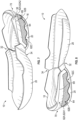
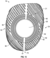
- the medial side elongated strip 62A1 shown in FIGS. 10 and 11 also has a first leg 90A extending upward in the direction from the bottom surface 56 of the foam core 16 toward the top edge 88 of the foam core 16, a second leg 90B extending from the first leg 90A at the front 73 of the foam core 16 and around the foam core 16 to the rear 70 of the foam core 16, and a third leg 90C extending from the second leg 90B downward toward the bottom surface 56 along the rear 70 of the foam core 16.
- the second portion 62B at the lateral side 34 extends from the first leg 90A to the third leg 90C below the second leg 90B.
- the second portion 62B extends in an uninterrupted span between the first leg 90A and the third leg 90C.
Landscapes
- Chemical & Material Sciences (AREA)
- Engineering & Computer Science (AREA)
- Materials Engineering (AREA)
- Footwear And Its Accessory, Manufacturing Method And Apparatuses (AREA)
Claims (15)
- Eine Sohlenstruktur (10) für einen Fußbekleidungsartikel (12), wobei die Sohlenstruktur (10) Folgendes umfasst:eine Sohlenkomponente (18) mit einer Bodenwand (36) und einer Umfangswand (38), die sich von der Bodenwand (36) nach oben erstreckt und einen Raum (40) über der Bodenwand (36) teilweise umgibt; undeine Zwischensohle (14), die einen Schaumstoffkern (16) beinhaltet, der im Raum (40) eingebettet ist;wobeidie Umfangswand (38) der Sohlenkomponente (18) außerhalb einer Seitenfläche (62) des Schaumstoffkerns (16) angeordnet ist; und wobei die Sohlenkomponente (18) an einem ersten Abschnitt (62A) der Seitenfläche (62) angebracht und von einem zweiten Abschnitt (62B) der Seitenfläche (62) gelöst ist, wobei der zweite Abschnitt (62B) der Seitenfläche (62) zwischen dem ersten Abschnitt (62A) und der Bodenwand (36) angeordnet ist,der zweite Abschnitt (62B) der Seitenfläche (62) des Schaumstoffkerns (16) ausgehend vom ersten Abschnitt (62A) nach innen vertieft ist, wodurch eine Lücke (76) zwischen einer Innenseite (49) der Umfangswand (38) der Sohlenkomponente (18) und dem zweiten Abschnitt (62B) der Seitenfläche (62) des Schaumstoffkerns (16) definiert wird, unddadurch gekennzeichnet, dassder zweite Abschnitt (62B) der Seitenfläche (62) des Schaumstoffkerns (16) sich unter Druckbelastung elastisch nach außen in die Lücke (76) verformt, und zwar in Richtung der Innenseite (49) der Umfangswand (38) der Sohlenkomponente (18).
- Die Sohlenstruktur (10) nach Anspruch 1, die ferner Folgendes umfasst:
eine Klebeschicht (78), die auf dem ersten Abschnitt (62A) der Seitenfläche (62) des Schaumstoffkerns (16) angeordnet ist und die Sohlenkomponente (18) an dem ersten Abschnitt (62A) der Seitenfläche (62) des Schaumstoffkerns (16) anklebt, wobei der zweite Abschnitt (62B) der Seitenfläche (62) frei von jeglicher Befestigung innerhalb des Raums (40) ist. - Die Sohlenstruktur (10) nach irgendeinem der vorstehenden Ansprüche, wobei:
die Bodenwand (36) der Sohlenkomponente (18) ein Durchgangsloch (46) aufweist und sich der Schaumstoffkern (16) über das Durchgangsloch (46) erstreckt. - Die Sohlenstruktur (10) nach irgendeinem der vorstehenden Ansprüche, wobei:
die Umfangswand (38) der Sohlenkomponente (18) sich angrenzend an und auswärts von der Seitenfläche (62) des Schaumstoffkerns (16) an einer medialen Seite (32), einer lateralen Seite (34) und einer Rückseite (70) der Sohlenstruktur (10) erstreckt. - Die Sohlenstruktur (10) nach Anspruch 4, wobei:die Umfangswand (38) der Sohlenkomponente (18) eine Kerbe (61) aufweist, die sich von einer Oberkante der Umfangswand (38) zur Bodenwand (36) der Sohlenkomponente (18) an der Rückseite (70) des Schaumstoffkerns (16) erstreckt; und wobeider Schaumstoffkern (16) sich über die Kerbe (61) einwärts von der Umfangswand (38) erstreckt.
- Die Sohlenstruktur (10) nach irgendeinem der vorstehenden Ansprüche, wobei:
der erste Abschnitt (62A) der Seitenfläche (62) des Schaumstoffkerns (16) einen länglichen Streifen (62A1, 62A2) beinhaltet, der sich in Längsrichtung der Sohlenstruktur (10) über dem zweiten Abschnitt (62B) von einer Vorderseite (73) des Schaumstoffkerns (16) zu einer Rückseite (70) des Schaumstoffkerns (16) erstreckt. - Die Sohlenstruktur (10) nach irgendeinem der Ansprüche von 1 bis 5, wobei:der erste Abschnitt (62A) der Seitenfläche (62) des Schaumstoffkerns (16) einen länglichen Streifen (62A1, 62A2) beinhaltet, der Folgendes aufweist: einen ersten Schenkel (86A, 90A), der sich von einer Bodenfläche (56) des Schaumstoffkerns (16) zu einer Oberkante (88) des Schaumstoffkerns (16) erstreckt, einen zweiten Schenkel (86B, 90B), der sich vom ersten Schenkel (86A, 90A) um den Schaumstoffkern (16) herum zu einer Rückseite (70) des Schaumstoffkerns (16) erstreckt, und einen dritten Schenkel (86C, 90C) am hinteren Ende (70) des Schaumstoffkerns (16), der sich vom zweiten Schenkel (86B, 90B) zur Bodenfläche (56) des Schaumstoffkerns (16) erstreckt; und wobeisich der zweite Abschnitt (62B) vom ersten Schenkel (86A, 90A) zum dritten Schenkel (86C, 90C) erstreckt, und zwar zwischen dem zweiten Schenkel (86B, 90B) und der Bodenfläche (56) des Schaumstoffkerns (16).
- Die Sohlenstruktur (10) nach Anspruch 7, wobei eine minimale Höhe (H1) des zweiten Abschnitts (62B) größer ist als eine maximale Höhe (H2) des zweiten Schenkels (86B, 90B).
- Die Sohlenstruktur (10) nach irgendeinem der vorstehenden Ansprüche, wobei:
der Schaumstoffkern (16) eine erste Steifigkeit aufweist und die Sohlenkomponente (18) eine zweite Steifigkeit aufweist, die größer ist als die erste Steifigkeit. - Die Sohlenstruktur (10) nach irgendeinem der vorstehenden Ansprüche, wobei die Sohlenkomponente (18) eine Außensohle ist und eine Bodenkontaktfläche der Sohlenstruktur (10) beinhaltet.
- Die Sohlenstruktur (10) nach Anspruch 10, die ferner Folgendes umfasst:
eine Zwischensohlenschicht (14), die sich zwischen einer oberen Fläche (44) der Sohlenkomponente (18) und einer Bodenfläche (56) des Schaumstoffkerns (16) erstreckt. - Die Sohlenstruktur (10) nach Anspruch 11, wobei:die Bodenfläche (56) des Schaumstoffkerns (16) an einer oberen Fläche (58) der Zwischensohlenschicht (20) befestigt ist; und wobeieine Bodenfläche (42) der Zwischensohlenschicht (20) an der oberen Fläche (58) der Sohlenkomponente (18) befestigt ist.
- Die Sohlenstruktur (10) nach Anspruch 11, wobei:der Schaumstoffkern (16) nur in einem Fersenbereich (24) der Sohlenstruktur (10) angeordnet ist; und wobeisich die Zwischensohlenschicht (20) von zwischen dem Schaumstoffkern (16) und der Sohlenkomponente (18) im Fersenbereich (24) nach vorne zu einem Mittelfußbereich (26) und einem Vorderfußbereich (28) der Sohlenstruktur (10) erstreckt.
- Die Sohlenstruktur (10) nach Anspruch 11, wobei:die Seitenfläche (62) des Schaumstoffkerns (16) einen dritten Abschnitt (62C) unterhalb des zweiten Abschnitts (62B) aufweist;der dritte Abschnitt (62C) gegenüber dem zweiten Abschnitt (62B) nach innen vertieft ist; und wobeidie Zwischensohlenschicht (20) an den dritten Abschnitt (62C) der Seitenfläche (62) des Schaumstoffkerns (16) gebunden ist.
- Die Sohlenstruktur (10) nach Anspruch 14, wobei:die Seitenfläche (62) des Schaumstoffkerns (16) eine gewellte Kante (64) zwischen dem zweiten Abschnitt (62B) und dem dritten Abschnitt (62C) definiert; und wobeidie Zwischensohlenschicht (20) eine gewellte Oberkante (50) aufweist, die mit der gewellten Kante (64) der Seitenfläche (62) des Schaumstoffkerns (16) zusammenpasst.
Priority Applications (1)
| Application Number | Priority Date | Filing Date | Title |
|---|---|---|---|
| EP25162268.4A EP4544947B1 (de) | 2020-04-07 | 2021-02-18 | Schuhsohlenstruktur mit verschachteltem schaumkern |
Applications Claiming Priority (2)
| Application Number | Priority Date | Filing Date | Title |
|---|---|---|---|
| US202063006286P | 2020-04-07 | 2020-04-07 | |
| PCT/US2021/018585 WO2021206812A1 (en) | 2020-04-07 | 2021-02-18 | Footwear sole structure with nested foam core |
Related Child Applications (1)
| Application Number | Title | Priority Date | Filing Date |
|---|---|---|---|
| EP25162268.4A Division EP4544947B1 (de) | 2020-04-07 | 2021-02-18 | Schuhsohlenstruktur mit verschachteltem schaumkern |
Publications (2)
| Publication Number | Publication Date |
|---|---|
| EP4096464A1 EP4096464A1 (de) | 2022-12-07 |
| EP4096464B1 true EP4096464B1 (de) | 2025-04-09 |
Family
ID=74870895
Family Applications (2)
| Application Number | Title | Priority Date | Filing Date |
|---|---|---|---|
| EP25162268.4A Active EP4544947B1 (de) | 2020-04-07 | 2021-02-18 | Schuhsohlenstruktur mit verschachteltem schaumkern |
| EP21711421.4A Active EP4096464B1 (de) | 2020-04-07 | 2021-02-18 | Schuhsohlenstruktur mit verschachteltem schaumkern |
Family Applications Before (1)
| Application Number | Title | Priority Date | Filing Date |
|---|---|---|---|
| EP25162268.4A Active EP4544947B1 (de) | 2020-04-07 | 2021-02-18 | Schuhsohlenstruktur mit verschachteltem schaumkern |
Country Status (5)
| Country | Link |
|---|---|
| US (1) | US11986046B2 (de) |
| EP (2) | EP4544947B1 (de) |
| CN (1) | CN115334925B (de) |
| TW (2) | TW202320661A (de) |
| WO (1) | WO2021206812A1 (de) |
Families Citing this family (7)
| Publication number | Priority date | Publication date | Assignee | Title |
|---|---|---|---|---|
| WO2021142428A1 (en) * | 2020-01-10 | 2021-07-15 | Nike Innovate C.V. | Sole structures having multiple hardnesses and/or flex promoting structures |
| EP4309538B1 (de) * | 2021-04-20 | 2025-07-02 | ASICS Corporation | Schuhsohle und schuh |
| CN116019283A (zh) * | 2022-10-14 | 2023-04-28 | 郭亭鹤 | 透气缓震鞋、透气缓震鞋底以及鞋底的制备方法 |
| USD1017992S1 (en) * | 2023-07-28 | 2024-03-19 | Nike, Inc. | Shoe |
| USD1017993S1 (en) * | 2023-07-28 | 2024-03-19 | Nike, Inc. | Shoe |
| USD1017994S1 (en) * | 2023-07-28 | 2024-03-19 | Nike, Inc. | Shoe |
| USD1017991S1 (en) * | 2023-07-28 | 2024-03-19 | Nike, Inc. | Shoe |
Family Cites Families (29)
| Publication number | Priority date | Publication date | Assignee | Title |
|---|---|---|---|---|
| FR2851130B1 (fr) * | 2003-02-14 | 2005-06-24 | Salomon Sa | Semelage de chaussure |
| WO1992003069A1 (en) * | 1990-08-21 | 1992-03-05 | Albert Ray Snow | Athletic shoe with a force responsive sole |
| US6665958B2 (en) | 2001-09-17 | 2003-12-23 | Nike, Inc. | Protective cage for footwear bladder |
| US6775932B2 (en) | 2002-09-06 | 2004-08-17 | Li Chieh Lin | Air bladder device having pattern changing mechanism |
| DE112005002327B4 (de) | 2004-09-30 | 2017-10-26 | Asics Corp. | Stoßabsorbierende Vorrichtung für eine Schuhsohle in einem Rückfußteil |
| US7464489B2 (en) * | 2005-07-27 | 2008-12-16 | Aci International | Footwear cushioning device |
| DE202005017306U1 (de) | 2005-11-05 | 2007-03-15 | Puma Aktiengesellschaft Rudolf Dassler Sport | Schuh, insbesondere Sportschuh |
| US9788603B2 (en) | 2007-10-23 | 2017-10-17 | Nike, Inc. | Articles and methods of manufacture of articles |
| US8082686B2 (en) | 2009-03-13 | 2011-12-27 | Under Armour, Inc. | Cleated athletic shoe with cushion structures |
| US9521877B2 (en) | 2013-02-21 | 2016-12-20 | Nike, Inc. | Article of footwear with outsole bonded to cushioning component and method of manufacturing an article of footwear |
| KR101047352B1 (ko) * | 2010-12-07 | 2011-07-07 | (주)지원에프알에스 | 충격흡수와 반발탄성력을 강화시킨 신발창 |
| US8869435B2 (en) | 2011-08-02 | 2014-10-28 | Nike, Inc. | Golf shoe with natural motion structures |
| KR101319821B1 (ko) * | 2011-09-01 | 2013-10-18 | (주)지원에프알에스 | 신발창 |
| KR101265080B1 (ko) * | 2011-11-22 | 2013-05-16 | (주)지원에프알에스 | 기능성 신발물품 |
| US9282784B2 (en) | 2012-09-06 | 2016-03-15 | Nike, Inc. | Sole structures and articles of footwear having a lightweight midsole with segmented protective elements |
| US9456658B2 (en) | 2012-09-20 | 2016-10-04 | Nike, Inc. | Sole structures and articles of footwear having plate moderated fluid-filled bladders and/or foam type impact force attenuation members |
| TW201544028A (zh) | 2014-05-26 | 2015-12-01 | Yiung Hsieh Footwear Co Ltd | 彈力避震鞋底結構 |
| EP3636096B1 (de) | 2014-11-12 | 2021-07-28 | NIKE Innovate C.V. | Verfahren zur herstellung einer sohlenanordnung für einen schuh |
| JP6679363B2 (ja) | 2015-03-23 | 2020-04-15 | アディダス アーゲー | ソールおよびシューズ |
| US10010133B2 (en) | 2015-05-08 | 2018-07-03 | Under Armour, Inc. | Midsole lattice with hollow tubes for footwear |
| US9615625B1 (en) | 2015-09-17 | 2017-04-11 | Wolverine Outdoors, Inc. | Sole assembly for article of footwear |
| CN109068798B (zh) | 2016-04-01 | 2021-08-17 | 耐克创新有限合伙公司 | 具有自适应配合的鞋类物品 |
| US20180103727A1 (en) * | 2016-10-19 | 2018-04-19 | Wolverine Outdoors, Inc. | Footwear construction with heel support assembly |
| KR102207241B1 (ko) | 2017-02-01 | 2021-01-22 | 나이키 이노베이트 씨.브이. | 밑창 구조체를 위한 적층형 완충 장치 |
| US10638812B2 (en) | 2017-05-24 | 2020-05-05 | Nike, Inc. | Flexible sole for article of footwear |
| JP6473201B1 (ja) | 2017-08-10 | 2019-02-20 | 美津濃株式会社 | シューズ |
| KR102432499B1 (ko) | 2018-04-20 | 2022-08-12 | 나이키 이노베이트 씨.브이. | 플레이트들 및 개재된 유체 충전 블래더를 구비하는 솔 구조체 및 제조 방법 |
| US11559106B2 (en) | 2019-10-24 | 2023-01-24 | Nike, Inc. | Article of footwear and method of manufacturing an article of footwear |
| EP3871549B1 (de) * | 2019-12-25 | 2023-09-20 | ASICS Corporation | Schuh und verfahren zur herstellung des schuhs |
-
2021
- 2021-02-18 EP EP25162268.4A patent/EP4544947B1/de active Active
- 2021-02-18 CN CN202180023117.XA patent/CN115334925B/zh active Active
- 2021-02-18 WO PCT/US2021/018585 patent/WO2021206812A1/en not_active Ceased
- 2021-02-18 EP EP21711421.4A patent/EP4096464B1/de active Active
- 2021-02-18 US US17/179,096 patent/US11986046B2/en active Active
- 2021-03-03 TW TW112102477A patent/TW202320661A/zh unknown
- 2021-03-03 TW TW110107421A patent/TWI794760B/zh active
Also Published As
| Publication number | Publication date |
|---|---|
| US11986046B2 (en) | 2024-05-21 |
| EP4544947A3 (de) | 2025-06-18 |
| TW202320661A (zh) | 2023-06-01 |
| EP4096464A1 (de) | 2022-12-07 |
| EP4544947A2 (de) | 2025-04-30 |
| CN115334925B (zh) | 2025-01-03 |
| WO2021206812A1 (en) | 2021-10-14 |
| CN115334925A (zh) | 2022-11-11 |
| EP4544947B1 (de) | 2026-02-18 |
| TWI794760B (zh) | 2023-03-01 |
| US20210307452A1 (en) | 2021-10-07 |
| TW202137904A (zh) | 2021-10-16 |
Similar Documents
| Publication | Publication Date | Title |
|---|---|---|
| EP4096464B1 (de) | Schuhsohlenstruktur mit verschachteltem schaumkern | |
| US11992085B2 (en) | Drop-in unitary footwear sole with first and second cushioning bodies of differing hardness | |
| EP3941297B1 (de) | Schuhwerk mit zonalem polstersystem | |
| US7946058B2 (en) | Article of footwear having a sole structure with an articulated midsole and outsole | |
| KR102766856B1 (ko) | 전방 모멘텀을 위한 중창 돌출부 및 아치형 프로파일을 갖는 밑창 구조체 | |
| KR102246212B1 (ko) | 신발류 물품, 그의 구성요소들 및 관련 제조 방법 | |
| EP2762027B1 (de) | Laufsohle mit Zapfen bildenden Nuten | |
| US20250248479A1 (en) | Article of footwear having a rand | |
| HK40080141A (en) | Footwear sole structure with nested foam core | |
| HK40080141B (zh) | 具有嵌套的泡沫芯的鞋类鞋底结构 | |
| HK40027748A (en) | Drop-in unitary footwear sole with first and second cushioning bodies of differing hardness | |
| HK40027748B (en) | Drop-in unitary footwear sole with first and second cushioning bodies of differing hardness |
Legal Events
| Date | Code | Title | Description |
|---|---|---|---|
| STAA | Information on the status of an ep patent application or granted ep patent |
Free format text: STATUS: UNKNOWN |
|
| STAA | Information on the status of an ep patent application or granted ep patent |
Free format text: STATUS: THE INTERNATIONAL PUBLICATION HAS BEEN MADE |
|
| PUAI | Public reference made under article 153(3) epc to a published international application that has entered the european phase |
Free format text: ORIGINAL CODE: 0009012 |
|
| STAA | Information on the status of an ep patent application or granted ep patent |
Free format text: STATUS: REQUEST FOR EXAMINATION WAS MADE |
|
| 17P | Request for examination filed |
Effective date: 20220901 |
|
| AK | Designated contracting states |
Kind code of ref document: A1 Designated state(s): AL AT BE BG CH CY CZ DE DK EE ES FI FR GB GR HR HU IE IS IT LI LT LU LV MC MK MT NL NO PL PT RO RS SE SI SK SM TR |
|
| P01 | Opt-out of the competence of the unified patent court (upc) registered |
Effective date: 20230515 |
|
| DAV | Request for validation of the european patent (deleted) | ||
| DAX | Request for extension of the european patent (deleted) | ||
| GRAP | Despatch of communication of intention to grant a patent |
Free format text: ORIGINAL CODE: EPIDOSNIGR1 |
|
| STAA | Information on the status of an ep patent application or granted ep patent |
Free format text: STATUS: GRANT OF PATENT IS INTENDED |
|
| INTG | Intention to grant announced |
Effective date: 20241108 |
|
| GRAS | Grant fee paid |
Free format text: ORIGINAL CODE: EPIDOSNIGR3 |
|
| GRAA | (expected) grant |
Free format text: ORIGINAL CODE: 0009210 |
|
| STAA | Information on the status of an ep patent application or granted ep patent |
Free format text: STATUS: THE PATENT HAS BEEN GRANTED |
|
| AK | Designated contracting states |
Kind code of ref document: B1 Designated state(s): AL AT BE BG CH CY CZ DE DK EE ES FI FR GB GR HR HU IE IS IT LI LT LU LV MC MK MT NL NO PL PT RO RS SE SI SK SM TR |
|
| REG | Reference to a national code |
Ref country code: GB Ref legal event code: FG4D |
|
| REG | Reference to a national code |
Ref country code: CH Ref legal event code: EP |
|
| REG | Reference to a national code |
Ref country code: DE Ref legal event code: R096 Ref document number: 602021028883 Country of ref document: DE |
|
| REG | Reference to a national code |
Ref country code: IE Ref legal event code: FG4D |
|
| REG | Reference to a national code |
Ref country code: NL Ref legal event code: MP Effective date: 20250409 |
|
| PG25 | Lapsed in a contracting state [announced via postgrant information from national office to epo] |
Ref country code: NL Free format text: LAPSE BECAUSE OF FAILURE TO SUBMIT A TRANSLATION OF THE DESCRIPTION OR TO PAY THE FEE WITHIN THE PRESCRIBED TIME-LIMIT Effective date: 20250409 |
|
| REG | Reference to a national code |
Ref country code: AT Ref legal event code: MK05 Ref document number: 1782693 Country of ref document: AT Kind code of ref document: T Effective date: 20250409 |
|
| PG25 | Lapsed in a contracting state [announced via postgrant information from national office to epo] |
Ref country code: ES Free format text: LAPSE BECAUSE OF FAILURE TO SUBMIT A TRANSLATION OF THE DESCRIPTION OR TO PAY THE FEE WITHIN THE PRESCRIBED TIME-LIMIT Effective date: 20250409 Ref country code: PT Free format text: LAPSE BECAUSE OF FAILURE TO SUBMIT A TRANSLATION OF THE DESCRIPTION OR TO PAY THE FEE WITHIN THE PRESCRIBED TIME-LIMIT Effective date: 20250811 Ref country code: FI Free format text: LAPSE BECAUSE OF FAILURE TO SUBMIT A TRANSLATION OF THE DESCRIPTION OR TO PAY THE FEE WITHIN THE PRESCRIBED TIME-LIMIT Effective date: 20250409 |
|
| REG | Reference to a national code |
Ref country code: LT Ref legal event code: MG9D |
|
| PG25 | Lapsed in a contracting state [announced via postgrant information from national office to epo] |
Ref country code: GR Free format text: LAPSE BECAUSE OF FAILURE TO SUBMIT A TRANSLATION OF THE DESCRIPTION OR TO PAY THE FEE WITHIN THE PRESCRIBED TIME-LIMIT Effective date: 20250710 Ref country code: NO Free format text: LAPSE BECAUSE OF FAILURE TO SUBMIT A TRANSLATION OF THE DESCRIPTION OR TO PAY THE FEE WITHIN THE PRESCRIBED TIME-LIMIT Effective date: 20250709 |
|
| PG25 | Lapsed in a contracting state [announced via postgrant information from national office to epo] |
Ref country code: PL Free format text: LAPSE BECAUSE OF FAILURE TO SUBMIT A TRANSLATION OF THE DESCRIPTION OR TO PAY THE FEE WITHIN THE PRESCRIBED TIME-LIMIT Effective date: 20250409 |
|
| PG25 | Lapsed in a contracting state [announced via postgrant information from national office to epo] |
Ref country code: BG Free format text: LAPSE BECAUSE OF FAILURE TO SUBMIT A TRANSLATION OF THE DESCRIPTION OR TO PAY THE FEE WITHIN THE PRESCRIBED TIME-LIMIT Effective date: 20250409 |
|
| PG25 | Lapsed in a contracting state [announced via postgrant information from national office to epo] |
Ref country code: HR Free format text: LAPSE BECAUSE OF FAILURE TO SUBMIT A TRANSLATION OF THE DESCRIPTION OR TO PAY THE FEE WITHIN THE PRESCRIBED TIME-LIMIT Effective date: 20250409 |
|
| PG25 | Lapsed in a contracting state [announced via postgrant information from national office to epo] |
Ref country code: AT Free format text: LAPSE BECAUSE OF FAILURE TO SUBMIT A TRANSLATION OF THE DESCRIPTION OR TO PAY THE FEE WITHIN THE PRESCRIBED TIME-LIMIT Effective date: 20250409 |
|
| PG25 | Lapsed in a contracting state [announced via postgrant information from national office to epo] |
Ref country code: RS Free format text: LAPSE BECAUSE OF FAILURE TO SUBMIT A TRANSLATION OF THE DESCRIPTION OR TO PAY THE FEE WITHIN THE PRESCRIBED TIME-LIMIT Effective date: 20250709 |
|
| PG25 | Lapsed in a contracting state [announced via postgrant information from national office to epo] |
Ref country code: IS Free format text: LAPSE BECAUSE OF FAILURE TO SUBMIT A TRANSLATION OF THE DESCRIPTION OR TO PAY THE FEE WITHIN THE PRESCRIBED TIME-LIMIT Effective date: 20250809 |
|
| PG25 | Lapsed in a contracting state [announced via postgrant information from national office to epo] |
Ref country code: LV Free format text: LAPSE BECAUSE OF FAILURE TO SUBMIT A TRANSLATION OF THE DESCRIPTION OR TO PAY THE FEE WITHIN THE PRESCRIBED TIME-LIMIT Effective date: 20250409 |
|
| REG | Reference to a national code |
Ref country code: DE Ref legal event code: R097 Ref document number: 602021028883 Country of ref document: DE |
|
| PG25 | Lapsed in a contracting state [announced via postgrant information from national office to epo] |
Ref country code: DK Free format text: LAPSE BECAUSE OF FAILURE TO SUBMIT A TRANSLATION OF THE DESCRIPTION OR TO PAY THE FEE WITHIN THE PRESCRIBED TIME-LIMIT Effective date: 20250409 Ref country code: SM Free format text: LAPSE BECAUSE OF FAILURE TO SUBMIT A TRANSLATION OF THE DESCRIPTION OR TO PAY THE FEE WITHIN THE PRESCRIBED TIME-LIMIT Effective date: 20250409 |
|
| PGFP | Annual fee paid to national office [announced via postgrant information from national office to epo] |
Ref country code: FR Payment date: 20251208 Year of fee payment: 6 |
|
| PG25 | Lapsed in a contracting state [announced via postgrant information from national office to epo] |
Ref country code: CZ Free format text: LAPSE BECAUSE OF FAILURE TO SUBMIT A TRANSLATION OF THE DESCRIPTION OR TO PAY THE FEE WITHIN THE PRESCRIBED TIME-LIMIT Effective date: 20250409 |
|
| PG25 | Lapsed in a contracting state [announced via postgrant information from national office to epo] |
Ref country code: EE Free format text: LAPSE BECAUSE OF FAILURE TO SUBMIT A TRANSLATION OF THE DESCRIPTION OR TO PAY THE FEE WITHIN THE PRESCRIBED TIME-LIMIT Effective date: 20250409 |
|
| PG25 | Lapsed in a contracting state [announced via postgrant information from national office to epo] |
Ref country code: SK Free format text: LAPSE BECAUSE OF FAILURE TO SUBMIT A TRANSLATION OF THE DESCRIPTION OR TO PAY THE FEE WITHIN THE PRESCRIBED TIME-LIMIT Effective date: 20250409 |
|
| PG25 | Lapsed in a contracting state [announced via postgrant information from national office to epo] |
Ref country code: IT Free format text: LAPSE BECAUSE OF FAILURE TO SUBMIT A TRANSLATION OF THE DESCRIPTION OR TO PAY THE FEE WITHIN THE PRESCRIBED TIME-LIMIT Effective date: 20250409 |
|
| PLBE | No opposition filed within time limit |
Free format text: ORIGINAL CODE: 0009261 |
|
| STAA | Information on the status of an ep patent application or granted ep patent |
Free format text: STATUS: NO OPPOSITION FILED WITHIN TIME LIMIT |
|
| REG | Reference to a national code |
Ref country code: CH Ref legal event code: L10 Free format text: ST27 STATUS EVENT CODE: U-0-0-L10-L00 (AS PROVIDED BY THE NATIONAL OFFICE) Effective date: 20260218 |
|
| 26N | No opposition filed |
Effective date: 20260112 |
|
| PGFP | Annual fee paid to national office [announced via postgrant information from national office to epo] |
Ref country code: GB Payment date: 20260106 Year of fee payment: 6 |
|
| PGFP | Annual fee paid to national office [announced via postgrant information from national office to epo] |
Ref country code: DE Payment date: 20251224 Year of fee payment: 6 |