EP4096115B1 - Orientierungsrichtungskontrollvorrichtung, optisches kommunikationsendgerät, optisches kommunikationssystem und orientierungsrichtungssteuerungsverfahren - Google Patents
Orientierungsrichtungskontrollvorrichtung, optisches kommunikationsendgerät, optisches kommunikationssystem und orientierungsrichtungssteuerungsverfahren Download PDFInfo
- Publication number
- EP4096115B1 EP4096115B1 EP20917928.2A EP20917928A EP4096115B1 EP 4096115 B1 EP4096115 B1 EP 4096115B1 EP 20917928 A EP20917928 A EP 20917928A EP 4096115 B1 EP4096115 B1 EP 4096115B1
- Authority
- EP
- European Patent Office
- Prior art keywords
- optical communication
- communication terminal
- error
- orientation direction
- unit
- Prior art date
- Legal status (The legal status is an assumption and is not a legal conclusion. Google has not performed a legal analysis and makes no representation as to the accuracy of the status listed.)
- Active
Links
Images




Classifications
-
- H—ELECTRICITY
- H04—ELECTRIC COMMUNICATION TECHNIQUE
- H04B—TRANSMISSION
- H04B7/00—Radio transmission systems, i.e. using radiation field
- H04B7/14—Relay systems
- H04B7/15—Active relay systems
- H04B7/185—Space-based or airborne stations; Stations for satellite systems
- H04B7/1851—Systems using a satellite or space-based relay
- H04B7/18515—Transmission equipment in satellites or space-based relays
-
- H—ELECTRICITY
- H04—ELECTRIC COMMUNICATION TECHNIQUE
- H04B—TRANSMISSION
- H04B10/00—Transmission systems employing electromagnetic waves other than radio-waves, e.g. infrared, visible or ultraviolet light, or employing corpuscular radiation, e.g. quantum communication
- H04B10/11—Arrangements specific to free-space transmission, i.e. transmission through air or vacuum
- H04B10/118—Arrangements specific to free-space transmission, i.e. transmission through air or vacuum specially adapted for satellite communication
-
- H—ELECTRICITY
- H04—ELECTRIC COMMUNICATION TECHNIQUE
- H04B—TRANSMISSION
- H04B7/00—Radio transmission systems, i.e. using radiation field
- H04B7/14—Relay systems
- H04B7/15—Active relay systems
- H04B7/185—Space-based or airborne stations; Stations for satellite systems
- H04B7/18521—Systems of inter linked satellites, i.e. inter satellite service
Definitions
- the present disclosure relates to an orientation direction control device to control an orientation direction in which light is transmitted and received.
- a disturbance of the satellite itself is problematic.
- the orientation direction in which the transmission/reception device transmits and receives the light or the radio wave deviates.
- the orientation direction may deviate due to other causes. If the orientation direction of the transmission/reception device deviates, communication quality may degrade.
- the transmission/reception device installed on the satellite has performance of maintaining accuracy of the orientation direction by correcting deviation in the orientation direction on the basis of light such as beacon light received from a transmission/reception device installed on another satellite other than the satellite (see, for example, Non-Patent Literature 1).
- US 2001/009466 A1 discloses a spatial light communication equipment being capable of providing compatibility between two spatial light communication equipments placed opposite to each other and of providing, with simplified configurations, highly accurate seizure and tracking capability and excellent beam directivity for ultra-long-distance communication.
- Non-Patent Literature 1 Optical Inter-Orbit Communication Technology: Future Space Communication Infrastructure (The Review of Laser Engineering, January 2011, Shiro Yamakawa, Takashi Jono, Japan Aerospace Exploration Agency)
- multiple transmission/reception devices are installed on the satellite to communicate with multiple other satellites or to observe the Earth while communicating with the other satellites.
- the communication quality it is necessary to improve the performance of maintaining the accuracy of the orientation direction for any of the transmission/reception devices. For that reason, there is a problem that it is necessary to provide equipment such as a high-performance sensor for any of the transmission/reception devices.
- the present disclosure has been made to solve the problem described above, and it is an object to provide a technology for maintaining the accuracy of the orientation direction without providing equipment such as a high-performance sensor for at least one or more transmission/reception devices among multiple transmission/reception devices installed on a satellite.
- the present disclosure it is possible to maintain the accuracy of the orientation direction without providing equipment such as a high-performance sensor, for at least one or more transmission/reception devices among multiple transmission/reception devices installed on a satellite.
- FIG. 1 is a schematic diagram illustrating a state in which an optical communication system 100 according to a first embodiment performs optical communication.
- the optical communication system 100 includes a first transmission/reception device to transmit and receive light and a second transmission/reception device to transmit and receive the light or a radio wave.
- the optical communication system 100 includes a first optical communication terminal 101 and a second optical communication terminal 102. Note that, in the first embodiment, a configuration will be described in which the optical communication system 100 includes two transmission/reception devices, the first optical communication terminal 101 as the first transmission/reception device and the second optical communication terminal 102 as the second transmission/reception device; however, the number of transmission/reception devices included in the optical communication system 100 is not particularly limited.
- the first optical communication terminal 101 and the second optical communication terminal 102 each are installed on a LEO satellite A.
- the first optical communication terminal 101 performs optical communication with a third optical communication terminal D installed on a GEO satellite C via a first optical link B.
- the second optical communication terminal 102 performs optical communication with a fourth optical communication terminal G installed on a LEO satellite F via a second optical link E.
- tellite means an artificial satellite.
- optical communication means that communication is performed by transmitting and receiving an optical signal to which data is added.
- LEO Low Earth Orbit
- GEO Geographical Earth Orbit
- the GEO satellite C is assumed to be a satellite that is stable and has a low disturbance as compared with the LEO satellite A and the LEO satellite F, and the LEO satellite A and the LEO satellite F are assumed to be satellites that have large disturbances as compared with the GEO satellite C.
- a role of the GEO satellite C is to provide a line that is not easily affected by the disturbance.
- the third optical communication terminal D may be provided in a low-disturbance LEO, medium earth orbit (MEO), or a ground station.
- the first optical communication terminal 101 performs optical communication with the third optical communication terminal D installed on the LEO, MEO, or the ground station via the first optical link B.
- a configuration of the first optical communication terminal 101 may be a configuration by which light is transmitted to a prism or a mirror installed on a stable place (for example, a planet) with less disturbance than the LEO satellite A and reflected light is received, instead of a configuration by which optical communication with the third optical communication terminal D is performed.
- optical communication also used in the following description is replaced with optical transmission and reception.
- FIG. 2 is a block diagram illustrating a configuration of the optical communication system 100 according to the first embodiment. As illustrated in FIG. 2 , the optical communication system 100 includes the first optical communication terminal 101 and the second optical communication terminal 102.
- the first optical communication terminal 101 includes a transmission/reception unit 1, an orientation direction control device 2, and a capture and tracking mechanism unit 3.
- the orientation direction control device 2 includes a receiving direction information acquisition unit 4, an error detection unit 5, and a capture and tracking control unit 6.
- the transmission/reception unit 1 By receiving light via the first optical link B, the transmission/reception unit 1 detects receiving direction information regarding a direction in which the light is received via the first optical link B. The transmission/reception unit 1 outputs the detected receiving direction information to the orientation direction control device 2. More specifically, the receiving direction information detected by the transmission/reception unit 1 is, for example, an incident direction of the light transmitted by the third optical communication terminal D of the GEO satellite C on the transmission/reception unit 1. Note that, the receiving direction information may include information regarding a position where the transmission/reception unit 1 receives the light via the first optical link B. In that case, the receiving direction information is, for example, an incident position of the light transmitted by the third optical communication terminal D of the GEO satellite C on the transmission/reception unit 1.
- the receiving direction information acquisition unit 4 acquires the receiving direction information detected by the transmission/reception unit 1.
- the receiving direction information acquisition unit 4 outputs the acquired receiving direction information to the error detection unit 5.
- the error detection unit 5 detects a first error of an orientation angle at which the first optical communication terminal 101 performs optical communication via the first optical link B, by referring to the receiving direction information acquired by the receiving direction information acquisition unit 4. More specifically, the error detection unit 5 detects the first error of the orientation angle at which the transmission/reception unit 1 of the first optical communication terminal 101 performs optical communication via the first optical link B, by referring to the receiving direction information acquired by the receiving direction information acquisition unit 4. The error detection unit 5 outputs the detected first error to the capture and tracking control unit 6, and an orientation direction control device 11 of the second optical communication terminal 102 described later.
- the error detected by the error detection unit 5 is a difference between the orientation angle at which the transmission/reception unit 1 performs optical communication via the first optical link B and a target orientation angle used for control by the capture and tracking control unit 6 described later.
- the error detection unit 5 may further detect an error of the position where the transmission/reception unit 1 performs optical communication via the first optical link B, by referring to the receiving direction information acquired by the receiving direction information acquisition unit 4.
- the error of the position detected by the error detection unit 5 is, for example, a difference between the position where the transmission/reception unit 1 performs optical communication via the first optical link B and a target position used for control by the capture and tracking control unit 6 described later.
- the capture and tracking control unit 6 controls capture and tracking for maintaining the first optical link B, by controlling an orientation direction in which the first optical communication terminal 101 performs optical communication via the first optical link B, on the basis of the first error detected by the error detection unit 5. More specifically, in the first embodiment, the capture and tracking control unit 6 controls the capture and tracking for maintaining the first optical link B, by controlling the orientation direction in which the transmission/reception unit 1 of the first optical communication terminal 101 performs optical communication via the first optical link B, on the basis of the first error detected by the error detection unit 5. For example, when controlling the orientation angle of the transmission/reception unit 1 to the target orientation angle, the capture and tracking control unit 6 adjusts an amount of control by an amount of the first error.
- the capture and tracking control unit 6 may control the capture and tracking for maintaining the first optical link B, by controlling the position where the transmission/reception unit 1 performs optical communication via the first optical link B, on the basis of the error of the position detected by the error detection unit 5.
- the capture and tracking mechanism unit 3 performs the capture and tracking for maintaining the first optical link B by changing the orientation direction of the transmission/reception unit 1 on the basis of control by the capture and tracking control unit 6. Note that, in a case where the capture and tracking control unit 6 controls the position of the transmission/reception unit 1 on the basis of the error of the position as described above, the capture and tracking mechanism unit 3 may perform the capture and tracking for maintaining the first optical link B, by further changing the position of the transmission/reception unit 1, on the basis of the control by the capture and tracking control unit 6.
- An example of the capture and tracking mechanism unit 3 is a piezo actuator or the like.
- the second optical communication terminal 102 includes a transmission/reception unit 10, the orientation direction control device 11, and a capture and tracking mechanism unit 12.
- the orientation direction control device 11 includes an orientation direction control information acquisition unit 13, an error value estimation calculation unit 14, a receiving direction information acquisition unit 15, an error detection unit 16, and a capture and tracking control unit 17.
- coarse capture means a state in which the second optical communication terminal 102 can perform tracking with the fourth optical communication terminal G by using beacon light or the like, or a state in which the second optical communication terminal 102 can perform capture by a tracking sensor of the transmission/reception unit 10 but cannot always perform capture by a communication sensor of the transmission/reception unit 10.
- the capture and tracking mechanism unit 12 that has received feedback has oscillated due to insufficient resolution of the tracking sensor of the transmission/reception unit 10 or control delay, due to satellite disturbance of the LEO satellite A.
- the transmission/reception unit 10 By receiving light via the second optical link E, the transmission/reception unit 10 detects receiving direction information regarding a direction in which the light is received via the second optical link E.
- the transmission/reception unit 10 outputs the received receiving direction information to the receiving direction information acquisition unit 15. More specifically, the receiving direction information is, for example, an incident direction of light transmitted by the fourth optical communication terminal G of the LEO satellite F on the transmission/reception unit 10.
- the receiving direction information may include information regarding a position where the transmission/reception unit 10 receives the light via the second optical link E. In that case, the receiving direction information is, for example, an incident position of the light transmitted by the fourth optical communication terminal G of the LEO satellite F on the transmission/reception unit 10.
- the orientation direction control information acquisition unit 13 acquires orientation direction control information for controlling the orientation direction in which the first optical communication terminal 101 transmits and receives light. More specifically, in the first embodiment, the orientation direction control information acquisition unit 13 acquires orientation direction control information including the first error of the orientation angle at which the transmission/reception unit 1 of the first optical communication terminal 101 performs optical communication via the first optical link B, from the error detection unit 5 of the orientation direction control device 2 of the first optical communication terminal 101. The orientation direction control information acquisition unit 13 outputs the acquired orientation direction control information to the error value estimation calculation unit 14.
- the orientation direction control information acquired by the orientation direction control information acquisition unit 13 may further include an error of a position where the transmission/reception unit 1 of the first optical communication terminal 101 performs optical communication via the first optical link B.
- the orientation direction control information acquisition unit 13 may further acquire at least one or more pieces of orientation direction control information from at least one or more optical communication terminals (not illustrated) installed on the LEO satellite A that are separate from the first optical communication terminal 101 and the second optical communication terminal 102.
- the error value estimation calculation unit 14 estimates a second error of an orientation angle at which the second optical communication terminal 102 performs optical communication via the second optical link E, on the basis of the first error acquired by the orientation direction control information acquisition unit 13. More specifically, the error value estimation calculation unit 14 estimates the second error of the orientation angle at which the transmission/reception unit 10 of the second optical communication terminal 102 performs optical communication via the second optical link E, on the basis of the first error acquired by the orientation direction control information acquisition unit 13.
- the error value estimation calculation unit 14 performs conversion to a disturbance value indicating a degree of disturbance of the LEO satellite A on the basis of the first error acquired by the orientation direction control information acquisition unit 13, and, on the basis of the disturbance value obtained by this conversion, estimates the second error of the orientation angle at which the transmission/reception unit 10 of the second optical communication terminal 102 performs optical communication via the second optical link E.
- the error value estimation calculation unit 14 may estimate an error of a position where the transmission/reception unit 10 of the second optical communication terminal 102 performs optical communication via the second optical link E, on the basis of the error of the position acquired by the orientation direction control information acquisition unit 13.
- the error value estimation calculation unit 14 may further estimate the second error of the orientation angle at which the second optical communication terminal 102 performs optical communication via the second optical link E, on the basis of errors in orientation angles of the at least one or more other optical communication terminals included in the at least one or more pieces of orientation direction control information acquired by the orientation direction control information acquisition unit 13.
- the receiving direction information acquisition unit 15 acquires the receiving direction information regarding a direction in which the second optical communication terminal 102 receives the light via the second optical link E. More specifically, in the first embodiment, the receiving direction information acquisition unit 15 acquires the receiving direction information regarding the direction in which the transmission/reception unit 10 of the second optical communication terminal 102 receives the light via the second optical link E. The receiving direction information acquisition unit 15 outputs the acquired receiving direction information to the error detection unit 16.
- the error detection unit 16 detects a third error of the orientation angle at which the second optical communication terminal 102 performs optical communication via the second optical link E, by referring to the receiving direction information acquired by the receiving direction information acquisition unit 15. More specifically, in the first embodiment, the error detection unit 16 detects the third error of the orientation angle at which the transmission/reception unit 10 of the second optical communication terminal 102 performs optical communication via the second optical link E, by referring to the receiving direction information acquired by the receiving direction information acquisition unit 15. The error detection unit 16 outputs the detected third error to the error value estimation calculation unit 14.
- the error value estimation calculation unit 14 outputs the estimated second error and the acquired third error to the capture and tracking control unit 17 as they are, or may calculate an error with higher accuracy than these errors on the basis of the second error and the third error, and output the error to the capture and tracking control unit 17.
- the error detected by the error detection unit 16 is a difference between the orientation angle at which the transmission/reception unit 10 performs optical communication via the second optical link E and a target orientation angle used for control by the capture and tracking control unit 17 described later.
- the error detection unit 16 may further detect the error of the position where the transmission/reception unit 10 performs optical communication via the second optical link E, by referring to the receiving direction information acquired by the receiving direction information acquisition unit 15.
- the error of the position detected by the error detection unit 16 is, for example, a difference between the position where the transmission/reception unit 10 performs optical communication via the second optical link E and a target position used for control by the capture and tracking control unit 17 described later.
- the capture and tracking control unit 17 is an orientation direction control unit to control an orientation direction in which the second optical communication terminal 102 as the second transmission/reception device transmits and receives the light or the radio wave, on the basis of the orientation direction control information acquired by the orientation direction control information acquisition unit 13. More specifically, in the first embodiment, the capture and tracking control unit 17 controls the capture and tracking for maintaining the second optical link E, by controlling an orientation direction in which the transmission/reception unit 10 of the second optical communication terminal 102 performs optical communication via the second optical link E, on the basis of the first error acquired by the orientation direction control information acquisition unit 13.
- the capture and tracking control unit 17 controls the capture and tracking for maintaining the second optical link E, by controlling the orientation direction in which the transmission/reception unit 10 of the second optical communication terminal 102 performs optical communication via the second optical link E, on the basis of the second error estimated on the basis of the first error by the error value estimation calculation unit 14. For example, when controlling the orientation angle of the transmission/reception unit 10 to the target orientation angle, the capture and tracking control unit 17 adjusts an amount of control by an amount of the second error.
- the capture and tracking control unit 17 controls the capture and tracking for maintaining the second optical link E, by controlling the orientation direction in which the transmission/reception unit 10 of the second optical communication terminal 102 performs optical communication via the second optical link E, further on the basis of the third error detected by the error detection unit 16.
- the capture and tracking control unit 17 may control the orientation direction in which the transmission/reception unit 10 performs optical communication via the second optical link E, for example, by using the second error as an amount of feedforward and the third error as an amount of feedback.
- the capture and tracking control unit 17 may control the capture and tracking for maintaining the second optical link E, by controlling a position where the transmission/reception unit 10 performs optical communication via the second optical link E, on the basis of the error of the position detected by the error detection unit 16.
- the capture and tracking control unit 17 may control the capture and tracking for maintaining the second optical link E, by controlling the orientation direction in which the transmission/reception unit 10 of the second optical communication terminal 102 performs optical communication via the second optical link E, further on the basis of the second error.
- the capture and tracking mechanism unit 12 performs the capture and tracking for maintaining the second optical link E by changing the orientation direction of the transmission/reception unit 10 on the basis of control by the capture and tracking control unit 17. Note that, in a case where the capture and tracking control unit 17 controls the position of the transmission/reception unit 10 on the basis of the error of the position as described above, the capture and tracking mechanism unit 12 may perform the capture and tracking for maintaining the second optical link E, by further changing the position of the transmission/reception unit 10, on the basis of the control by the capture and tracking control unit 17.
- An example of the capture and tracking mechanism unit 12 is a piezo actuator or the like.
- FIG. 3 is a flowchart illustrating an orientation direction control method by the orientation direction control device 2. Note that, before the following orientation direction control method is implemented, the transmission/reception unit 1 is assumed to detect receiving direction information regarding the direction in which the light is received via the first optical link B, by receiving the light via the first optical link B.
- the receiving direction information acquisition unit 4 acquires the receiving direction information detected by the transmission/reception unit 1 (step ST1).
- the receiving direction information acquisition unit 4 outputs the acquired receiving direction information to the error detection unit 5.
- the error detection unit 5 detects the first error of the orientation angle at which the transmission/reception unit 1 performs optical communication via the first optical link B, by referring to the receiving direction information acquired by the receiving direction information acquisition unit 4 (step ST2).
- the error detection unit 5 outputs the detected first error to the capture and tracking control unit 6 and the orientation direction control information acquisition unit 13 of the orientation direction control device 11 of the second optical communication terminal 102.
- the capture and tracking control unit 6 controls the capture and tracking for maintaining the first optical link B, by controlling the orientation direction in which the transmission/reception unit 1 performs optical communication via the first optical link B, on the basis of the first error detected by the error detection unit 5 (step ST3).
- the capture and tracking mechanism unit 3 performs the capture and tracking for maintaining the first optical link B by changing the orientation direction of the transmission/reception unit 1 on the basis of the control by the capture and tracking control unit 6 in step ST3.
- the transmission/reception unit 1 whose orientation direction has been changed by the capture and tracking mechanism unit 3 detects receiving direction information regarding the direction in which the light is received via the first optical link B, by receiving the light via the first optical link B again.
- the orientation direction control device 2 executes steps ST1 to ST3 again on the basis of the receiving direction information detected again by the transmission/reception unit 1.
- the first optical communication terminal 101 performs the capture and tracking for maintaining the first optical link B, by repeating the operation described above.
- FIG. 4 is a flowchart illustrating an orientation direction control method by the orientation direction control device 11. Note that, before the following orientation direction control method is implemented, the transmission/reception unit 10 is assumed to detect the receiving direction information regarding the direction in which light is received via the second optical link E, by receiving the light via the second optical link E.
- the orientation direction control information acquisition unit 13 acquires the orientation direction control information including the first error of the orientation angle at which the transmission/reception unit 1 of the first optical communication terminal 101 performs optical communication via the first optical link B, from the error detection unit 5 of the orientation direction control device 2 of the first optical communication terminal 101 (step ST10).
- the orientation direction control information acquisition unit 13 outputs the acquired orientation direction control information to the error value estimation calculation unit 14.
- the error value estimation calculation unit 14 estimates the second error of the orientation angle at which the transmission/reception unit 10 performs optical communication via the second optical link E, on the basis of the first error acquired by the orientation direction control information acquisition unit 13 (step ST11).
- the receiving direction information acquisition unit 15 acquires the receiving direction information regarding the direction in which the transmission/reception unit 10 receives the light via the second optical link E (step ST12).
- the receiving direction information acquisition unit 15 outputs the acquired receiving direction information to the error detection unit 16.
- the error detection unit 16 detects the third error of the orientation angle at which the transmission/reception unit 10 performs optical communication via the second optical link E, by referring to the receiving direction information acquired by the receiving direction information acquisition unit 15 (step ST13).
- the error detection unit 16 outputs the detected third error to the error value estimation calculation unit 14.
- the error value estimation calculation unit 14 outputs the second error estimated in step ST 11 and the acquired third error to the capture and tracking control unit 17.
- the capture and tracking control unit 17 controls the capture and tracking for maintaining the second optical link E, by controlling the orientation direction in which the transmission/reception unit 10 performs optical communication via the second optical link E, on the basis of the second error estimated on the basis of the first error by the error value estimation calculation unit 14 in step ST11 and the third error detected by the error detection unit 16 in step ST13 (step ST14).
- the capture and tracking mechanism unit 12 performs the capture and tracking for maintaining the second optical link E by changing the orientation direction of the transmission/reception unit 10 on the basis of the control by the capture and tracking control unit 17 in step ST14.
- the transmission/reception unit 10 whose orientation direction has been changed by the capture and tracking mechanism unit 12 detects the receiving direction information regarding the direction in which the light is received via the second optical link E, by receiving the light via the second optical link E again. Then, the orientation direction control device 11 executes steps ST10 to ST14 described above again.
- the second optical communication terminal 102 performs the capture and tracking for maintaining the second optical link E by repeating the operation described above.
- the orientation direction control device 2 includes the processing circuit for executing the processing from step ST1 to step ST3 illustrated in FIG. 3 .
- the processing circuit may be dedicated hardware, or a central processing unit (CPU) for executing a program stored in a memory.
- orientation direction control device 11 includes the processing circuit for executing the processing from step ST10 to step ST14 illustrated in FIG. 4 .
- the processing circuit may be dedicated hardware, or a central processing unit (CPU) for executing a program stored in a memory.
- FIG. 5A is a block diagram illustrating a hardware configuration for implementing a function of the orientation direction control device 2 or the orientation direction control device 11.
- FIG. 5B is a block diagram illustrating a hardware configuration for executing software for implementing the function of the orientation direction control device 2 or the orientation direction control device 11.
- the transmission/reception device 21 illustrated in each of FIGS. 5A and 5B executes the function of the transmission/reception unit 1 or the function of the transmission/reception unit 10.
- the capture and tracking mechanism 22 illustrated in each of FIGS. 5A and 5B executes the function of the capture and tracking mechanism unit 3 or the function of the capture and tracking mechanism unit 12.
- processing circuit is a processing circuitry 20 of the dedicated hardware illustrated in FIG. 5A
- examples of the processing circuitry 20 include a single circuit, a composite circuit, a programmed processor, a parallel-programmed processor, an application specific integrated circuit (ASIC), a field-programmable gate array (FPGA), or a combination thereof.
- ASIC application specific integrated circuit
- FPGA field-programmable gate array
- the functions of the receiving direction information acquisition unit 4, the error detection unit 5, and the capture and tracking control unit 6 in the orientation direction control device 2 may be implemented by separate processing circuits, or these functions may be collectively implemented by one processing circuit.
- the functions of the orientation direction control information acquisition unit 13, the error value estimation calculation unit 14, the receiving direction information acquisition unit 15, the error detection unit 16, and the capture and tracking control unit 17 in the orientation direction control device 11 may be implemented by separate processing circuits, or these functions may be collectively implemented by one processing circuit.
- the functions of the receiving direction information acquisition unit 4, the error detection unit 5, and the capture and tracking control unit 6 in the orientation direction control device 2 are implemented by software, firmware, or a combination of software and firmware.
- the functions of the orientation direction control information acquisition unit 13, the error value estimation calculation unit 14, the receiving direction information acquisition unit 15, the error detection unit 16, and the capture and tracking control unit 17 in the orientation direction control device 11 are implemented by software, firmware, or a combination of software and firmware.
- the software or the firmware is described as a program and stored in a memory 24.
- the processor 23 implements the functions of the receiving direction information acquisition unit 4, the error detection unit 5, and the capture and tracking control unit 6 in the orientation direction control device 2 by reading and executing the program stored in the memory 24. That is, the orientation direction control device 2 includes the memory 24 for storing a program by which the processing from step ST1 to step ST3 illustrated in FIG. 3 is resultantly executed when executed by the processor 23.
- the processor 23 implements the functions of the orientation direction control information acquisition unit 13, the error value estimation calculation unit 14, the receiving direction information acquisition unit 15, the error detection unit 16, and the capture and tracking control unit 17 in the orientation direction control device 11 by reading and executing the program stored in the memory 24. That is, the orientation direction control device 11 includes the memory 24 for storing a program by which the processing from step ST10 to step ST14 illustrated in FIG. 4 is resultantly executed when executed by the processor 23.
- These programs cause a computer to execute procedures or methods performed by the receiving direction information acquisition unit 4, the error detection unit 5, and the capture and tracking control unit 6 in the orientation direction control device 2.
- the memory 24 may be a computer-readable storage medium in which a program is stored for causing the computer to function as the receiving direction information acquisition unit 4, the error detection unit 5, and the capture and tracking control unit 6 in the orientation direction control device 2.
- these programs cause a computer to execute procedures or methods performed by the orientation direction control information acquisition unit 13, the error value estimation calculation unit 14, the receiving direction information acquisition unit 15, the error detection unit 16, and the capture and tracking control unit 17 in the orientation direction control device 11.
- the memory 24 may be a computer-readable storage medium in which a program is stored for causing the computer to function as the orientation direction control information acquisition unit 13, the error value estimation calculation unit 14, the receiving direction information acquisition unit 15, the error detection unit 16, and the capture and tracking control unit 17 in the orientation direction control device 11.
- Examples of the memory 24 include a nonvolatile or volatile semiconductor memory such as random access memory (RAM), read only memory (ROM), flash memory, erasable programmable read only memory (EPROM), and electrically-EPROM (EEPROM), a magnetic disk, a flexible disk, an optical disk, a compact disk, a mini disk, a DVD, and the like.
- RAM random access memory
- ROM read only memory
- EPROM erasable programmable read only memory
- EEPROM electrically-EPROM
- the functions of the receiving direction information acquisition unit 4, the error detection unit 5, and the capture and tracking control unit 6 in the orientation direction control device 2 some of the functions may be implemented by dedicated hardware, and some of the functions may be implemented by software or firmware.
- the receiving direction information acquisition unit 4 and the error detection unit 5 implement the functions by a processing circuit as dedicated hardware.
- the processor 23 may implement the function by reading and executing the program stored in the memory 24.
- the functions of the orientation direction control information acquisition unit 13, the error value estimation calculation unit 14, the receiving direction information acquisition unit 15, the error detection unit 16, and the capture and tracking control unit 17 in the orientation direction control device 11 may be implemented by dedicated hardware, and some of the functions may be implemented by software or firmware.
- the orientation direction control information acquisition unit 13 and the error value estimation calculation unit 14 implement the functions by a processing circuit as dedicated hardware.
- the processor 23 may implement the functions by reading and executing the program stored in the memory 24.
- the processing circuit can implement each of the functions by hardware, software, firmware, or a combination thereof.
- FIG. 6 is a schematic diagram for explaining a specific example of the error value estimation method by the orientation direction control device 11. Note that, for simplicity of explanation, FIG. 6 illustrates a two-dimensional positional relationship between the satellites described above.
- ⁇ is defined as an angle formed by a line (first optical link B) connecting the LEO satellite A with the GEO satellite C and a line (second optical link E) connecting the LEO satellite A with the LEO satellite F. Note that precision capture is assumed to be established between the LEO satellite A and the GEO satellite C.
- step ST2 the error detection unit 5 of the orientation direction control device 2 of the first optical communication terminal 101 detects a first error ⁇ of the orientation angle at which the transmission/reception unit 1 performs optical communication via the first optical link B, during a certain time interval ⁇ t.
- the orientation direction control information acquisition unit 13 acquires the first error ⁇ in step ST10 described above.
- step ST11 the error value estimation calculation unit 14 of the second optical communication terminal 102 estimates that the second error of the orientation angle at which the transmission/reception unit 10 performs optical communication via the second optical link E is the same value as the first error ⁇ of the orientation angle at which the transmission/reception unit 1 of the first optical communication terminal 101 performs optical communication via the first optical link B.
- a second error ⁇ estimated by the error value estimation calculation unit 14 is used for control of the orientation direction by the capture and tracking control unit 17 in step ST14 described above, whereby the second optical link E between the LEO satellite A and the LEO satellite F is stabilized.
- FIG. 7 is a block diagram illustrating a specific example of the orientation direction control method according to the first embodiment.
- the capture and tracking control unit 6 is assumed to have calculated the amount of control for the capture and tracking mechanism unit 3 by using the target orientation angle (input in FIG. 7 ) and the first error acquired in advance from the error detection unit 5 as inputs, and G11 as a transfer function, and to have controlled the orientation direction in which the transmission/reception unit 1 performs optical communication via the first optical link B.
- the capture and tracking mechanism unit 3 performs the capture and tracking for maintaining the first optical link B, by changing the orientation direction of the transmission/reception unit 1, on the basis of the control by the capture and tracking control unit 6 in step ST3.
- the transmission/reception unit 1 whose orientation direction has been changed by the capture and tracking mechanism unit 3 detects the receiving direction information regarding the direction in which the light is received via the first optical link B, by receiving the light via the first optical link B.
- the orientation direction control method by the orientation direction control device 2 is executed again, and in step ST1 described above, the receiving direction information acquisition unit 4 acquires the receiving direction information detected by the transmission/reception unit 1.
- the error detection unit 5 calculates the first error of the orientation angle at which the transmission/reception unit 1 performs optical communication via the first optical link B, by using the receiving direction information acquired by the receiving direction information acquisition unit 4 as an input, and G12 as a transfer function.
- step ST3 the capture and tracking control unit 6 calculates again the amount of control for the capture and tracking mechanism unit 3 by using the target orientation angle and the first error calculated by the error detection unit 5 as inputs, and G11 as a transfer function, and controls the orientation direction in which the transmission/reception unit 1 performs optical communication via the first optical link B. That is, in the specific example, the control by the capture and tracking control unit 6 is feedback control using the first error as an amount of feedback.
- the capture and tracking control unit 17 is assumed to have controlled the capture and tracking for maintaining the second optical link E, by calculating an amount of control for the capture and tracking mechanism unit 12 by using the target orientation angle, the second error acquired in advance from the error value estimation calculation unit 14, and the third error acquired in advance from the error detection unit 16 as inputs, and G21 as a transfer function, and controlling the orientation direction in which the transmission/reception unit 10 performs optical communication via the second optical link E. Then, the capture and tracking mechanism unit 12 performs the capture and tracking for maintaining the second optical link E, by changing the orientation direction of the transmission/reception unit 10, on the basis of the control by the capture and tracking control unit 17 in step ST14.
- the transmission/reception unit 10 whose orientation direction has been changed by the capture and tracking mechanism unit 12 detects receiving direction information regarding the direction in which the light is received via the second optical link E, by receiving the light via the second optical link E.
- the orientation direction control method by the orientation direction control device 11 is executed again, and in the step ST10 described above, the orientation direction control information acquisition unit 13 acquires the orientation direction control information including the first error calculated by the error detection unit 5 in step ST2 described above.
- the error value estimation calculation unit 14 calculates the second error of the orientation angle at which the transmission/reception unit 10 performs optical communication via the second optical link E, by using the first error acquired by the orientation direction control information acquisition unit 13 as an input, and G13 as a transfer function.
- the receiving direction information acquisition unit 15 acquires the receiving direction information regarding the direction in which the transmission/reception unit 10 receives the light via the second optical link E.
- the error detection unit 16 calculates the third error of the orientation angle at which the transmission/reception unit 10 performs optical communication via the second optical link E, by using the receiving direction information acquired by the receiving direction information acquisition unit 15 as an input, and G22 as a transfer function.
- the capture and tracking control unit 17 controls the capture and tracking for maintaining the second optical link E by calculating the amount of control for the capture and tracking mechanism unit 12 by using the target orientation angle, the second error calculated by the error value estimation calculation unit 14 in step ST11, and the third error calculated by the error detection unit 16 in step ST13 as inputs, and G21 as a transfer function, and controlling the orientation direction in which the transmission/reception unit 10 performs optical communication via the second optical link E. That is, in the specific example, the control by the capture and tracking control unit 6 is control in which feedback control using the third error as an amount of feedback and feedforward control using the second error as an amount of feedforward are used in combination.
- FIG. 8 is a schematic diagram illustrating a state in which an optical communication system 103 according to the first modification of the first embodiment performs optical communication and observation.
- the optical communication system 103 includes the first optical communication terminal 101 and an observation terminal 104.
- a configuration of the first optical communication terminal 101 according to the first modification is similar to a configuration of the first optical communication terminal 101 illustrated in FIG. 2 .
- a configuration of the observation terminal 104 according to the first modification is partially different from the configuration of the second optical communication terminal 102 illustrated in FIG. 2 .
- the observation terminal 104 observes the Earth by transmitting and receiving light or a radio wave.
- Examples of the observation terminal 104 include an observation terminal including an optical element for ground imaging, an observation terminal including a radio wave processing device for ground imaging, an observation terminal including a measuring device for measuring atmospheric conditions, or the like.
- a transmission/reception unit corresponding to the transmission/reception unit 10 of the second optical communication terminal 102 in the observation terminal 104 includes the optical element for ground imaging, the radio wave processing device for ground imaging, or the measuring device for measuring atmospheric conditions.
- the transmission/reception unit may detect receiving direction information regarding a direction in which the light or the radio wave is received, by a method similar to the method described above in which the transmission/reception unit 10 of the second optical communication terminal 102 detects receiving direction information.
- the transmission/reception unit may detect the receiving direction information regarding the direction in which the light or the radio wave is received, by transmitting the light or the radio wave toward the Earth and receiving the reflected light or radio wave.
- An orientation direction control unit corresponding to the capture and tracking control unit 17 of the second optical communication terminal 102 in the observation terminal 104 controls an orientation direction in which the transmission/reception unit of the observation terminal 104 transmits and receives the light or the radio wave, on the basis of the first error acquired by the orientation direction control information acquisition unit 13. More specifically, the orientation direction control unit controls the orientation direction in which the transmission/reception unit of the observation terminal 104 transmits and receives the light or the radio wave, on the basis of the second error estimated on the basis of the first error by the error value estimation calculation unit 14. Further more specifically, the orientation direction control unit controls the orientation direction in which the transmission/reception unit of the observation terminal 104 transmits and receives the light or the radio wave, further on the basis of the third error detected by the error detection unit 16.
- a mechanism unit corresponding to the capture and tracking mechanism unit 12 of the second optical communication terminal 102 in the observation terminal 104 adjusts an observation direction by changing the orientation direction of the transmission/reception unit 10 on the basis of control by the orientation direction control unit.
- the orientation direction control device 11 can be applied to the observation terminal 104 by partially changing its configuration.
- the orientation direction control device 11 of the second optical communication terminal 102 controls the orientation direction on the basis of the first error acquired from the orientation direction control device 2 of the first optical communication terminal 101.
- the orientation direction control device 2 of the first optical communication terminal 101 has a configuration similar to the described configuration.
- FIG. 9 is a block diagram illustrating a configuration of an optical communication system 105 according to the second modification of the first embodiment.
- an orientation direction control device 30 of a first optical communication terminal 106 according to the second modification further includes an orientation direction control information acquisition unit 31 and an error value estimation calculation unit 32 as compared with the orientation direction control device 2 described above.
- the orientation direction control information acquisition unit 31 acquires the third error detected by the error detection unit 16 of the second optical communication terminal 102.
- the error value estimation calculation unit 32 estimates a fourth error of the orientation angle at which the transmission/reception unit 1 performs optical communication via the first optical link B, on the basis of the third error acquired by the orientation direction control information acquisition unit 31.
- the capture and tracking control unit 6 controls the capture and tracking for maintaining the first optical link B, by controlling the orientation direction in which the transmission/reception unit 1 performs optical communication via the first optical link B, further on the basis of the fourth error estimated on the basis of the third error by the error value estimation calculation unit 32.
- the capture and tracking capability for maintaining the first optical link B by the first optical communication terminal 101 is improved.
- the orientation direction control device 11 is the orientation direction control device 11 to control an orientation direction in which, in a satellite on which the first optical communication terminal 101 as the first transmission/reception device to transmit and receive the light and the second optical communication terminal 102 as the second transmission/reception device to transmit and receive the light or the radio wave are installed, the second transmission/reception device transmits and receives the light or the radio wave, and includes: the orientation direction control information acquisition unit 13 to acquire the orientation direction control information for controlling the orientation direction in which the first transmission/reception device transmits and receives the light; and the capture and tracking control unit 17 as the orientation direction control unit to control the orientation direction in which the second transmission/reception device transmits and receives the light or the radio wave, on the basis of the orientation direction control information acquired by the orientation direction control information acquisition unit 13.
- the first transmission/reception device and the second transmission/reception device are installed on the same satellite, there is a correlation between the orientation direction of the first transmission/reception device and the orientation direction of the second transmission/reception device.
- an orientation direction in which the other transmission/reception device transmits and receives light or a radio wave may be controlled on the basis of the orientation direction control information of the first transmission/reception device. That is, it is possible to maintain the accuracy of the orientation direction without providing equipment such as a high-performance sensor, for at least one or more transmission/reception devices among multiple transmission/reception devices installed on a satellite. In addition, as a result, it is possible to reduce cost of equipment of the transmission/reception device.
- the first transmission/reception device is the first optical communication terminal 101 to perform optical communication via the first optical link B
- the second transmission/reception device is the second optical communication terminal 102 to perform optical communication via the second optical link E
- the orientation direction control information acquired by the orientation direction control information acquisition unit 13 includes the first error of the orientation angle at which the first optical communication terminal 101 performs optical communication via the first optical link B
- the orientation direction control unit is the capture and tracking control unit 17 to control the capture and tracking for maintaining the second optical link E, by controlling the orientation direction in which the second optical communication terminal 102 performs optical communication via the second optical link E, on the basis of the first error acquired by the orientation direction control information acquisition unit 13.
- the above configuration it is possible to correct deviation in the orientation direction of the second optical communication terminal 102 due to the disturbance of the LEO satellite A, or the like, and maintain the accuracy of the orientation of the second optical communication terminal 102, by controlling the orientation direction of the second optical communication terminal 102, on the basis of the first error of the orientation angle of the first optical communication terminal 101. That is, it is possible to maintain the accuracy of the orientation direction without providing equipment such as a high-performance sensor, for at least one or more optical communication terminals among a plurality of optical communication terminals installed on a satellite.
- the orientation direction control device 11 further includes the error value estimation calculation unit 14 to estimate the second error of the orientation angle at which the second optical communication terminal 102 performs optical communication via the second optical link E, on the basis of the first error acquired by the orientation direction control information acquisition unit 13, in which the capture and tracking control unit 17 controls the capture and tracking for maintaining the second optical link E, by controlling the orientation direction in which the second optical communication terminal 102 performs optical communication via the second optical link E, on the basis of the second error estimated on the basis of the first error by the error value estimation calculation unit 14.
- the second error of the orientation angle of the second optical communication terminal 102 is estimated on the basis of the first error of the orientation angle of the first optical communication terminal 101, and the orientation direction of the second optical communication terminal 102 is controlled on the basis of the second error.
- the orientation direction of the second optical communication terminal 102 can be suitably controlled.
- the orientation direction control device 11 further includes: the receiving direction information acquisition unit 15 to acquire the receiving direction information regarding the direction in which the second optical communication terminal 102 receives the light via the second optical link E; and the error detection unit 16 to detect the third error of the orientation angle at which the second optical communication terminal 102 performs optical communication via the second optical link E, by referring to the receiving direction information acquired by the receiving direction information acquisition unit 15, in which the capture and tracking control unit 17 controls the capture and tracking for maintaining the second optical link E, by controlling the orientation direction in which the second optical communication terminal 102 performs optical communication via the second optical link E, further on the basis of the third error detected by the error detection unit 16.
- the orientation direction of the second optical communication terminal 102 is controlled, further on the basis of the third error of the orientation direction of the second optical communication terminal 102.
- the accuracy of the orientation direction of the second optical communication terminal 102 can be suitably maintained.
- the first transmission/reception device is the first optical communication terminal 101 to perform optical communication via the first optical link B
- the second transmission/reception device is the observation terminal 104 to observe the Earth by transmitting and receiving the light or the radio wave
- the orientation direction control information acquired by the orientation direction control information acquisition unit 13 is an error of the orientation angle at which the first optical communication terminal 101 performs optical communication via the first optical link B
- the capture and tracking control unit 17 as the orientation direction control unit controls the orientation direction in which the observation terminal 104 transmits and receives the light or the radio wave, on the basis of the error acquired by the orientation direction control information acquisition unit 13.
- the second optical communication terminal 102 includes: the orientation direction control device 11; the transmission/reception unit 10 (second optical communication terminal transmission/reception unit) to detect the receiving direction information of the second optical communication terminal 102 by receiving the light via the second optical link E; and the capture and tracking mechanism unit 12 (second optical communication terminal capture and tracking mechanism unit) to perform the capture and tracking for maintaining the second optical link E, by changing the orientation direction of the transmission/reception unit 10, on the basis of the control by the capture and tracking control unit 17.
- the capture and tracking mechanism unit 12 changes the orientation direction of the transmission/reception unit 10 by control based on the third error by the capture and tracking control unit 17, whereby the accuracy of the orientation direction of the second optical communication terminal 102 can be suitably maintained.
- the optical communication system 100 includes the second optical communication terminal 102 and the first optical communication terminal 101
- the first optical communication terminal 101 includes: the transmission/reception unit 1 (first optical communication terminal transmission/reception unit) to detect the receiving direction information regarding the direction in which the light is received via the first optical link B, by receiving the light via the first optical link B; the receiving direction information acquisition unit 4 (first optical communication terminal receiving direction information acquisition unit) to acquire the receiving direction information detected by the transmission/reception unit 1; the error detection unit 5 (first optical communication terminal error detection unit) to detect the first error of the orientation angle at which the first optical communication terminal 101 performs optical communication via the first optical link B, by referring to the receiving direction information acquired by the receiving direction information acquisition unit 4; the capture and tracking control unit 6 (first optical communication terminal capture and tracking control unit) to control the capture and tracking for maintaining the first optical link B, by controlling the orientation direction in which the first optical communication terminal 101 performs optical communication via the first optical link B, on the basis of the first error detected by the error detection unit 5; and
- the first optical communication terminal 101 can suitably maintain the accuracy of the orientation direction by controlling the orientation direction of the transmission/reception unit 1 of the first optical communication terminal 101 on the basis of the first error detected by the error detection unit 5.
- the first optical communication terminal 106 in the optical communication system 105 further includes: the orientation direction control information acquisition unit 31 (first optical communication terminal orientation direction control information acquisition unit) to acquire the third error detected by the error detection unit 16 of the second optical communication terminal 102; and the error value estimation calculation unit 32 (first optical communication terminal error value estimation calculation unit) to estimate the fourth error of the orientation angle at which the transmission/reception unit 1 performs optical communication via the first optical link B, on the basis of the third error acquired by the orientation direction control information acquisition unit 31, in which the capture and tracking control unit 6 controls the capture and tracking for maintaining the first optical link B, by controlling the orientation direction in which the transmission/reception unit 1 performs optical communication via the first optical link B, further on the basis of the fourth error estimated on the basis of the third error by the error value estimation calculation unit 32.
- the orientation direction control information acquisition unit 31 first optical communication terminal orientation direction control information acquisition unit
- the error value estimation calculation unit 32 first optical communication terminal error value estimation calculation unit
- the orientation direction control method is an orientation direction control method for controlling the orientation direction in which, in the satellite on which the first optical communication terminal 101 as the first transmission/reception device to transmit and receive the light and the second optical communication terminal 102 as the second transmission/reception device to transmit and receive the light or the radio wave are installed, the second transmission/reception device transmits and receives the light or the radio wave
- the orientation control method includes: an orientation direction control information acquisition step of acquiring the orientation direction control information for controlling the orientation direction in which the first transmission/reception device transmits and receives the light; and an orientation direction control step of controlling the orientation direction in which the second transmission/reception device transmits and receives the light or the radio wave, on the basis of the orientation direction control information acquired in the orientation direction control information acquisition step.
- an optical communication terminal of a single satellite communicates with optical communication terminals of multiple satellites and switches communication targets (Starlink of SpaceX, or the like).
- communication between the optical communication terminals is interrupted during a time required for the optical communication terminal to capture when switching the communication targets, which is a factor of lowering an operating ratio of the optical communication terminal. For that reason, being able to shorten the time for switching the communication targets means that an amount of communication between the satellites can be increased.
- one orientation direction control device controls the orientation direction, further on the basis of an orientation angle for control used by the other orientation direction control device, in addition to the configuration of the first embodiment, whereby the time required for capture is shortened.
- FIG. 10 is a schematic diagram illustrating a state in which the optical communication system 107 according to the second embodiment performs optical communication.
- the optical communication system 107 includes the first optical communication terminal 101 and a second optical communication terminal 108.
- the first optical communication terminal 101 and the second optical communication terminal 108 each are installed on the LEO satellite A.
- the first optical communication terminal 101 performs optical communication with the third optical communication terminal D installed on the GEO satellite C via the first optical link B.
- the second optical communication terminal 108 performs optical communication with the fourth optical communication terminal G installed on the LEO satellite F via the second optical link E.
- the GEO satellite C is a satellite that is stable and has a low disturbance as compared with the LEO satellite A and the LEO satellite F.
- a fifth optical communication terminal H is installed on the GEO satellite C
- a sixth optical communication terminal I is installed on the LEO satellite F.
- the fifth optical communication terminal H and the sixth optical communication terminal I communicate with each other via a third optical link J.
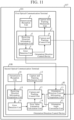
- FIG. 11 is a block diagram illustrating a configuration of the optical communication system 107 according to the second embodiment.
- the optical communication system 107 includes the second optical communication terminal 108 instead of the second optical communication terminal 102.
- an orientation direction control device 40 in the second optical communication terminal 108, further includes an orientation angle conversion unit 41.
- the orientation direction control information acquisition unit 13 further acquires a first orientation angle for control used for controlling the orientation direction in which the first optical communication terminal 101 performs optical communication via the first optical link B, as the orientation direction control information. More specifically, the orientation direction control information acquisition unit 13 further acquires the first orientation angle for control used for controlling the orientation direction in which the first optical communication terminal 101 performs optical communication via the first optical link B, as the orientation direction control information, from the capture and tracking control unit 6 of the orientation direction control device 2 of the first optical communication terminal 101. The orientation direction control information acquisition unit 13 outputs the acquired first orientation angle to the orientation angle conversion unit 41.
- the orientation angle conversion unit 41 converts the first orientation angle acquired by the orientation direction control information acquisition unit 13 to a second orientation angle for control used for controlling an orientation direction in which the second optical communication terminal 108 performs optical communication via the second optical link E, and outputs the converted second orientation angle to the capture and tracking control unit 17.
- the capture and tracking control unit 17 controls the capture and tracking for maintaining the second optical link E, by controlling the orientation direction in which the second optical communication terminal 108 performs optical communication via the second optical link E, further on the basis of the first orientation angle acquired by the orientation direction control information acquisition unit 13. More specifically, in the second embodiment, the capture and tracking control unit 17 controls the capture and tracking for maintaining the second optical link E, by controlling the orientation direction in which the transmission/reception unit 10 performs optical communication via the second optical link E, further on the basis of the second orientation angle converted on the basis of the first orientation angle by the orientation angle conversion unit 41.
- the capture and tracking control unit 17 may estimate a position of the second optical communication terminal 108 on the basis of the second orientation angle converted on the basis of the first orientation angle by the orientation angle conversion unit 41, and orbit information regarding an orbit of the LEO satellite A. In that case, the capture and tracking control unit 17 may control the capture and tracking for maintaining the second optical link E, by controlling the position where the transmission/reception unit 10 performs optical communication via the second optical link E, on the basis of the estimated position.
- orientation direction control device 40 of the second optical communication terminal 108 operation of the orientation direction control device 40 of the second optical communication terminal 108 according to the second embodiment will be described with reference to the drawings.
- operation of the orientation direction control device 2 of the first optical communication terminal 101 according to the second embodiment is similar to the operation of the orientation direction control device 2 described in the first embodiment except that the capture and tracking control unit 6 outputs the first orientation angle for control used for controlling the orientation direction in which the first optical communication terminal 101 performs optical communication via the first optical link B, to the orientation direction control information acquisition unit 13 of the orientation direction control device 40 of the second optical communication terminal 108. For that reason, a description will be omitted of the operation of the orientation direction control device 2 of the first optical communication terminal 101 according to the second embodiment.
- FIG. 12 is a flowchart illustrating an orientation direction control method by the orientation direction control device 40. Note that, before the following orientation direction control method is implemented, the transmission/reception unit 10 is assumed to detect the receiving direction information regarding the direction in which light is received via the second optical link E, by receiving the light via the second optical link E.
- the orientation direction control information acquisition unit 13 acquires the orientation direction control information including the first error of the orientation angle at which the transmission/reception unit 1 of the first optical communication terminal 101 performs optical communication via the first optical link B, from the error detection unit 5 of the orientation direction control device 2 of the first optical communication terminal 101 (step ST20).
- the orientation direction control information acquisition unit 13 outputs the acquired orientation direction control information to the error value estimation calculation unit 14.
- the error value estimation calculation unit 14 estimates the second error of the orientation angle at which the transmission/reception unit 10 performs optical communication via the second optical link E, on the basis of the first error acquired by the orientation direction control information acquisition unit 13 (step ST21).
- the orientation direction control information acquisition unit 13 further acquires the first orientation angle for control used for controlling the orientation direction in which the first optical communication terminal 101 performs optical communication via the first optical link B, as the orientation direction control information, from the capture and tracking control unit 6 of the orientation direction control device 2 of the first optical communication terminal 101 (step ST22).
- the orientation direction control information acquisition unit 13 outputs the acquired first orientation angle to the orientation angle conversion unit 41.
- the orientation angle conversion unit 41 converts the first orientation angle acquired by the orientation direction control information acquisition unit 13 to the second orientation angle for control used for controlling the orientation direction in which the second optical communication terminal 108 performs optical communication via the second optical link E (step ST23).
- the orientation angle conversion unit 41 outputs the converted second orientation angle to the capture and tracking control unit 17.
- the receiving direction information acquisition unit 15 acquires the receiving direction information regarding the direction in which the transmission/reception unit 10 receives the light via the second optical link E (step ST24).
- the receiving direction information acquisition unit 15 outputs the acquired receiving direction information to the error detection unit 16.
- the error detection unit 16 detects the third error of the orientation angle at which the transmission/reception unit 10 performs optical communication via the second optical link E, by referring to the receiving direction information acquired by the receiving direction information acquisition unit 15 (step ST25).
- the error detection unit 16 outputs the detected third error to the error value estimation calculation unit 14.
- the error value estimation calculation unit 14 outputs the second error estimated in step ST21 and the third error acquired from the error detection unit 16 to the capture and tracking control unit 17.
- the capture and tracking control unit 17 controls the capture and tracking for maintaining the second optical link E, by controlling the orientation direction in which the transmission/reception unit 10 performs optical communication via the second optical link E, on the basis of the second error estimated on the basis of the first error by the error value estimation calculation unit 14 in step ST21, the second orientation angle converted by the orientation angle conversion unit 41 in step ST23, and the third error detected by the error detection unit 16 in step ST25 (step ST26).
- the capture and tracking mechanism unit 12 performs the capture and tracking for maintaining the second optical link E, by changing the orientation direction of the transmission/reception unit 10, on the basis of the control by the capture and tracking control unit 17 in step ST26.
- the transmission/reception unit 10 whose orientation direction has been changed by the capture and tracking mechanism unit 12 detects the receiving direction information regarding the direction in which the light is received via the second optical link E, by receiving the light via the second optical link E again. Then, the orientation direction control device 40 executes steps ST20 to ST26 described above again.
- the second optical communication terminal 108 performs the capture and tracking for maintaining the second optical link E by repeating the operation described above.
- the orientation direction control device 40 according to the second embodiment includes the processing circuit for executing the processing from step ST20 to step ST26 illustrated in FIG. 12 .
- the processing circuit may be dedicated hardware, or a central processing unit (CPU) for executing a program stored in a memory.
- a hardware configuration for implementing a function of the orientation direction control device 40 according to the second embodiment is similar to the hardware configuration illustrated in FIG. 5A .
- a hardware configuration for executing software for implementing the function of the orientation direction control device 40 according to the second embodiment is similar to the hardware configuration illustrated in FIG. 5B .
- FIG. 13 is a diagram for explaining the effect of the orientation direction control method by the orientation direction control device 40.
- step ST26 the capture and tracking control unit 17 controls the capture and tracking for maintaining the second optical link E, by controlling the orientation direction in which the transmission/reception unit 10 performs optical communication via the second optical link E, on the basis of the second error estimated on the basis of the first error by the error value estimation calculation unit 14 in step ST21.
- influence due to the disturbance of the LEO satellite A is suppressed and an error range of the orientation angle is narrowed (one-dot chain line in FIG. 13 ), so that the scan range when the second optical communication terminal 108 performs a spiral scan or the like is narrowed.
- the capture and tracking control unit 17 controls the capture and tracking for maintaining the second optical link E, by controlling the orientation direction in which the transmission/reception unit 10 performs optical communication via the second optical link E, on the basis of the second orientation angle converted by the orientation angle conversion unit 41 in step ST23.
- the capture and tracking control unit 17 controls the capture and tracking for maintaining the second optical link E, by controlling the orientation direction in which the transmission/reception unit 10 performs optical communication via the second optical link E, on the basis of the second orientation angle converted by the orientation angle conversion unit 41 in step ST23.
- the LEO satellite A includes three or more optical communication terminals.
- the LEO satellite A establishes a link with a plurality of low-disturbance satellites, and the orientation direction control device 40 controls the orientation direction further on the basis of the orientation angle for control used for control the orientation direction in which each optical communication terminal (not illustrated) with established links with the plurality of low-disturbance satellites performs optical communication, whereby an estimation range after correction of the attitude error can be further narrowed.
- it is effective in shortening the time required for capture.
- the orientation direction control information acquired by the orientation direction control information acquisition unit 13 further includes the first orientation angle for control used for controlling the orientation direction in which the first optical communication terminal 101 performs optical communication via the first optical link B, and the capture and tracking control unit 17 controls the capture and tracking for maintaining the second optical link E, by controlling the orientation direction in which the second optical communication terminal 108 performs optical communication via the second optical link E, further on the basis of the first orientation angle acquired by the orientation direction control information acquisition unit 13.
- the above configuration it is possible to correct the deviation in the orientation direction of the second optical communication terminal 108 due to the attitude error of the LEO satellite A, and it is possible to maintain the accuracy of the orientation direction of the second optical communication terminal 108, by controlling the orientation direction in which the second optical communication terminal 108 performs optical communication via the second optical link E, further on the basis of the first orientation angle for control in the first optical communication terminal 101.
- the scan range when the second optical communication terminal 108 performs a spiral scan or the like is narrowed.
- the orientation direction control device 40 further includes the orientation angle conversion unit 41 to convert the first orientation angle acquired by the orientation direction control information acquisition unit 13 to the second orientation angle for control used for controlling the orientation direction in which the second optical communication terminal 108 performs optical communication via the second optical link E, and the capture and tracking control unit 17 controls the capture and tracking for maintaining the second optical link E, by controlling the orientation direction in which the second optical communication terminal 108 performs optical communication via the second optical link E, further on the basis of the second orientation angle converted on the basis of the first orientation angle by the orientation angle conversion unit 41.
- the orientation direction control device can maintain the accuracy of the orientation direction without providing equipment such as a high-performance sensor, for at least one or more transmission/reception devices among multiple transmission/reception devices installed on a satellite, so that the orientation direction control device can be used for optical communication systems.
Landscapes
- Physics & Mathematics (AREA)
- Engineering & Computer Science (AREA)
- Astronomy & Astrophysics (AREA)
- General Physics & Mathematics (AREA)
- Computer Networks & Wireless Communication (AREA)
- Signal Processing (AREA)
- Electromagnetism (AREA)
- Aviation & Aerospace Engineering (AREA)
- Optical Communication System (AREA)
- Vehicle Body Suspensions (AREA)
Claims (7)
- Orientierungsrichtung-Steuerungseinrichtung (11, 40) zum Steuern einer Orientierungsrichtung, in der eine zweite Übertragungs-/Empfangseinrichtung (102, 108) Licht überträgt und empfängt, wobeieine erste Übertragungs-/Empfangseinrichtung (101, 106), die eingerichtet ist, Licht zu übertragen und zu empfangen, und die zweite Übertragungs-/Empfangseinrichtung (102, 108), die eingerichtet ist, das Licht zu übertragen und zu empfangen, an einem Satelliten installiert sind, wobei die erste Übertragungs-/Empfangseinrichtung (101, 106) ein erstes optisches Kommunikations-Endgerät ist, das eingerichtet ist, optische Kommunikation über eine erste optische Verbindung durchzuführen, und die zweite Übertragungs-/Empfangseinrichtung (102, 108) ein zweites optisches Kommunikations-Endgerät ist, das eingerichtet ist, optische Kommunikation über eine zweite optische Verbindung durchzuführen, undwobei die Orientierungsrichtung-Steuerungseinrichtung (11, 40) umfasst:eine Orientierungsrichtung-Steuerungsinformationen-Erwerbungseinheit (13), die eingerichtet ist, Orientierungsrichtung-Steuerungsinformationen zur Steuerung einer Orientierungsrichtung zu erwerben, in welcher die erste Übertragungs-/Empfangseinrichtung (101, 106) das Licht überträgt und empfängt, wobei die durch die Orientierungsrichtung-Steuerungsinformationen-Erwerbungseinheit (13) erworbenen Orientierungsrichtung-Steuerungsinformationen einen ersten Fehler eines Orientierungswinkels enthalten, bei dem das erste optische Kommunikations-Endgerät (101, 106) optische Kommunikation über die erste optische Verbindung durchführt, und der erste Fehler eine Differenz zwischen dem Orientierungswinkel, bei dem das erste optische Kommunikations-Endgerät optische Kommunikation über die erste optische Verbindung durchführt, und einem Ziel-Orientierungswinkel ist;eine Orientierungsrichtungs-Steuerungseinheit (17), die eingerichtet ist, die Orientierungsrichtung, in welcher die zweite Übertragungs-/Empfangseinrichtung (102, 108) das Licht überträgt und empfängt, zu steuern;eine Fehlerwertschätzung-Berechnungseinheit (14), die eingerichtet ist, den ersten Fehler von der Orientierungsrichtung-Steuerungsinformationen-Erwerbungseinheit (13) zu empfangen, um Umwandlung in einen Störungswert, der einen Grad der Störung des Satelliten angibt, auf der Grundlage des ersten Fehlers, der durch die Orientierungsrichtung-Steuerungsinformationen-Erwerbungseinheit (13) erworben wird, durchzuführen, und einen zweiten Fehler eines Orientierungswinkels, bei welchem das zweite optische Kommunikations-Endgerät (102, 108) optische Kommunikation über die zweite optische Verbindung durchführt, auf der Grundlage des Störungswerts, der durch diese Umwandlung erhalten wird, zu schätzen;eine Empfangsrichtungsinformation-Erwerbungseinheit (15), die eingerichtet ist, Empfangsrichtungsinformationen bezüglich einer Richtung, in welcher das zweite optische Kommunikations-Endgerät (102, 108) Licht über die zweite optische Verbindung empfängt, zu erwerben; undeine Fehler-Erfassungseinheit (16), die eingerichtet ist, die Empfangsrichtungsinformationen zu empfangen, um einen dritten Fehler des Orientierungswinkels zu erfassen, bei dem das zweite optische Kommunikations-Endgerät (102, 108) optische Kommunikation über die zweite optische Verbindung durch Bezugnahme auf die von der Empfangsrichtungsinformationen-Erwerbungseinheit (15) erworbenen Empfangsrichtungsinformationen durchführt, und die eingerichtet ist, den dritten Fehler an die Fehlerwertschätzung-Berechnungseinheit (14) auszugeben,wobei der dritte Fehler eine Differenz zwischen dem Orientierungswinkel, bei welchem das zweite optische Kommunikations-Endgerät optische Kommunikation über die zweite optische Verbindung durchführt, und dem Ziel-Orientierungswinkel ist, unddie Orientierungsrichtung-Steuerungseinheit (17) eine Erfassungs- und-Verfolgungs-Steuerungseinheit (17) ist, die eingerichtet ist, den zweiten Fehler und den dritten Fehler von der Fehlerwertschätzung-Berechnungseinheit (14) zu empfangen, und die eingerichtet ist, Erfassung und Verfolgung zur Aufrechterhaltung der zweiten optischen Verbindung steuert, indem eine Orientierungsrichtung gesteuert wird, in welcher das zweite optische Kommunikations-Endgerät (102, 108) optische Kommunikation über die zweite optische Verbindung durchführt,auf der Grundlage des zweiten Fehlers, der auf der Grundlage des ersten Fehlers von der Fehlerwertschätzung-Berechnungseinheit geschätzt wird, und ferner auf der Grundlage des dritten Fehlers, der von der Fehler-Erfassungseinheit erfasst wird.
- Orientierungsrichtung-Steuerungseinrichtung (40) nach Anspruch 1, wobeidie Orientierungsrichtung-Steuerungsinformationen, die von der Orientierungsrichtung-Steuerungsinformations-Erwerbungseinheit (13) erworben werden, ferner einen ersten Orientierungswinkel zur Steuerung enthalten, der zur Steuerung einer Orientierungsrichtung eingesetzt wird, in welcher das erste optische Kommunikations-Endgerät (101) optische Kommunikation über die erste optische Verbindung durchführt, unddie Erfassungs-und-Verfolgungs-Steuerungseinheit (17) eingerichtet ist, die Erfassung und Verfolgung zur Aufrechterhaltung der zweiten optischen Verbindung zu steuern, indem die Orientierungsrichtung gesteuert wird, in welcher das zweite optische Kommunikations-Endgerät (108) optische Kommunikation über die zweite optische Verbindung durchführt, ferner auf der Grundlage des ersten Orientierungswinkels, der von der Orientierungsrichtung-Steuerungsinformationen-Erwerbungseinheit (13) erworben wird.
- Orientierungsrichtung-Steuerungseinrichtung (40) nach Anspruch 2, ferner umfassend:eine Orientierungswinkel-Umwandlungseinheit (41), die eingerichtet ist, den ersten Orientierungswinkel, der von der Orientierungsrichtung-Steuerungsinformationen-Erwerbungseinheit (13) erworben wird, in einen zweiten Orientierungswinkel zur Steuerung, der zur Steuerung der Orientierungsrichtung genutzt wird, in welcher das zweite optische Kommunikations-Endgerät (108) optische Kommunikation über die zweite optische Verbindung durchführt, umzuwandeln, wobeidie Erfassungs-und-Verfolgungs-Steuerungseinheit (17) eingerichtet ist, die Erfassung und Verfolgung zur Aufrechterhaltung der zweiten optischen Verbindung zu steuern, indem die Orientierungsrichtung, in welcher das zweite optische Kommunikations-Endgerät (108) optische Kommunikation über die zweite optische Verbindung durchführt, ferner auf der Grundlage des zweiten Orientierungswinkels, der auf der Grundlage des ersten Orientierungswinkels durch die Orientierungswinkel-Umwandlungseinheit (41) umgewandelt wird.
- Optisches Kommunikations-Endgerät (102, 108) als das zweite optische Kommunikations-Endgerät (102, 108), umfassend:die Orientierungsrichtung-Steuerungseinrichtung (11, 40) nach Anspruch 1,eine Zweites-Optisches-Kommunikations-Endgerät-Übertragungs-/Empfangseinheit (10), die eingerichtet ist, die Empfangsrichtungsinformationen des zweiten optischen Kommunikations-Endgeräts (102, 108) durch Empfangen von Licht über die zweite optische Verbindung zu erfassen, undeine Zweites-Optisches-Kommunikations-Endgerät-Erfassungs-und-Verfolgungs-Mechanismuseinheit (12), die eingerichtet ist, Erfassung und Verfolgung zur Aufrechterhaltung der zweiten optischen Verbindung durch Ändern einer Orientierungsrichtung der Zweites-Optisches-Kommunikations-Endgerät-Übertragungs-/Empfangseinheit (10) auf der Grundlage einer Steuerung durch die Erfassungs-und-Verfolgungs-Steuerungseinheit (17) durchzuführen.
- Optisches Kommunikationssystem (100, 105, 107), umfassend:ein optisches Kommunikations-Endgerät als das zweite optische Kommunikations-Endgerät (102, 108) nach Anspruch 4, und das erste optische Kommunikations-Endgerät (101, 106), wobeidas erste optische Kommunikations-Endgerät (101, 106) umfasst:eine Erstes-Optisches-Kommunikations-Endgerät-Übertragungs-/Empfangseinheit (1), die eingerichtet ist, Empfangsrichtungsinformationen bezüglich einer Richtung, in welcher Licht über die erste optische Verbindung empfangen wird, indem das Licht über die erste optische Verbindung empfangen wird, zu erfassen;eine Erstes-Optisches-Kommunikations-Endgerät-Empfangsrichtungsinformationen-Erwerbungseinheit (4), die eingerichtet ist, die Empfangsrichtungsinformation, die durch die Erstes-Optisches-Kommunikationsendgerät-Übertragungs-/Empfangseinheit (1) erfasst werden, zu erwerben;eine Erstes-Optsiches-Kommunikations-Endgerät-Fehler-Erfassungseinheit (5), die eingerichtet ist, den ersten Fehler des Orientierungswinkels, bei welchem das erste optische Kommunikations-Endgerät (101, 106) optische Kommunikation über die erste optische Verbindung durchführt, zu erfassen, indem auf die Empfangsrichtungsinformationen Bezug genommen wird, die von der Erstes-Optisches-Kommunikations-Endgerät-Empfangsrichtungsinformations-Erwerbungseinheit (4) erworben werden;eine Erstes-Optisches-Kommunikations-Endgerät-Erfassungs-und-Verfolgungs-Steuerungseinheit (6), die eingerichtet ist, Erfassung und Verfolgung zur Aufrechterhaltung der ersten optischen Verbindung zu steuern, indem eine Orientierungsrichtung gesteuert wird, in welcher das erste optische Kommunikations-Endgerät (101, 106) optische Kommunikation über die erste optische Verbindung durchführt, auf der Grundlage des ersten Fehlers, der von der Erstes-Optisches-Kommunikations-Endgerät-Fehler-Erfassungseinheit (5) erfasst wird; undeine Erstes-Optisches-Kommunikations-Endgerät-Erfassungs-und-Verfolgungs-Mechanismuseinheit (3), die eingerichtet ist, Erfassung und Verfolgung zum Aufrechterhalten der ersten optischen Verbindung durch Ändern einer Orientierungsrichtung der Erstes-Optisches-Kommunikations-Endgerät-Übertragungs-/Empfangseinheit (1) durchzuführen, auf der Grundlage einer Steuerung durch die Erstes-Optisches-Kommunikations-Endgerät-Erfassungs-und-Verfolgungs-Steuerungseinheit (6).
- Optisches Kommunikationssystem (105) nach Anspruch 5, wobei
das erste optische Kommunikations-Endgerät (101, 106) ferner umfasst:eine Erstes-Optisches-Kommunikations-Endgerät-Orientierungssteuerungsinformationen-Erwerbungseinheit (31), die eingerichtet ist, einen dritten Fehler zu erwerben, der von der Fehler-Erfassungseinheit (16) des zweiten optischen Kommunikations-Endgeräts (102, 108) erfasst wird; undeine Erstes-Optisches-Kommunikations-Endgerät-Fehlerwert-Schätzungs-Berechnungseinheit (32), die eingerichtet ist, einen vierten Fehler eines Orientierungswinkels, bei welchem die Erestes-Optisches-Kommunikationsendgerät-Übertragungs-/Empfangseinheit (1) optische Kommunikation über die erste optische Verbindung durchführt, zu schätzen, auf der Grundlage des dritten Fehlers, der von der Erstes-Optisches-Kommunikations-Endgerät-Orientierungsrichtung-Steuerungsinformationen-Erwerbungseinheit (31) erworben wird, unddie Erstes-Optisches-Kommunikations-Endgerät-Erfassungs-und-Verfolgungs-Steuerungseinheit (6), die eingerichtet ist, die Erfassung und Verfolgung zur Aufrechterhaltung der ersten optischen Verbindung zu steuern, indem eine Orientierungsrichtung, in welcher die Erstes-Optisches-Kommunikations-Endgerät-Übertragungs-/Empfangseinheit (1) optische Kommunikation über die erste optische Verbindung durchführt, ferner auf der Grundlage des vierten Fehlers, der auf der Grundlage des dritten Fehlers durch die Erstes-Optisches-Kommunikations-Endgerät-Fehlerwert-Schätzung-Berechnungseinheit (32) geschätzt wird. - Orientierungsrichtung-Steuerungsverfahren zum Steuern einer Orientierungsrichtung, in welcher eine zweite Übertragungs-/Empfangseinrichtung (102, 108) Licht überträgt und empfängt, wobeieine erste Übertragungs-/Empfangseinrichtung (101, 106), die eingerichtet ist, Licht zu übertragen und zu empfangen, und die zweite Übertragungs-/Empfangseinrichtung (102, 108), die eingerichtet ist, das Licht zu übertragen und zu empfangen, an einem Satelliten installiert sind, wobei die erste Übertragungs-/Empfangseinrichtung (101, 106) ein erstes optisches Kommunikations-Endgerät ist, das eingerichtet ist, optische Kommunikation über eine erste optische Verbindung durchzuführen, und die zweite Übertragungs-/Empfangseinrichtung (102, 108) ein zweites optisches Kommunikations-Endgerät ist, das eingerichtet ist, optische Kommunikation über eine zweite optische Verbindung durchzuführen, unddas Orientierungsrichtung-Steuerungsverfahren umfasst:einen Orientierungsrichtung-Steuerungsinformationen-Erwerbungsschritt des Erwerbens von Orientierungsrichtung-Steuerungsinformationen zum Steuern einer Orientierungsrichtung, in welcher die erste Übertragungs-/Empfangseinrichtung (101, 106) das Licht überträgt und empfängt, wobei die in dem Orientierungsrichtung-Steuerungsinformationen-Erwerbungsschritt erworbenen Orientierungsrichtung-Steuerungsinformationen einen ersten Fehler eines Orientierungswinkels enthalten, bei welchem das erste optische Kommunikations-Endgerät (101, 106) optische Kommunikation über die erste optische Verbindung durchführt, und der erste Fehler eine Differenz zwischen dem Orientierungswinkel, bei welchem das erste optische Kommunikations-Endgerät optische Kommunikation über die erste optische Verbindung durchführt, und einem Ziel-Orientierungswinkel ist;einen Orientierungsrichtung-Steuerungsschritt des Steuerns der Orientierungsrichtung, in welcher die zweite Übertragungs-/Empfangseinrichtung (102, 108) das Licht überträgt und empfängt;einen Fehlerwert-Schätzung-Berechnungsschritt des Empfangens des ersten Fehlers, der in dem Orientierungsrichtung-Steuerungsinformationen-Erwerbungsschritt erworben wurde, des Durchführens einer Umwandlung in einen Störungswert, der einen Grad der Störung des Satelliten angibt, auf der Grundlage des ersten Fehlers, der in dem Orientierungsrichtung-Steuerungsinformationen-Erwerbungsschritt erworben wurde, und des Schätzens eines zweiten Fehlers eines Orientierungswinkels, bei welchem das zweite optische Kommunikations-Endgerät (102, 108) optische Kommunikation über die zweite optische Verbindung durchführt, auf der Grundlage des Störungswerts, der durch diese Umwandlung erhalten wurde;einen Empfangsrichtungsinformationen-Erwerbungsschritt des Erwerbens von Empfangsrichtungsinformationen bezüglich einer Richtung, in welcher das zweite optische Kommunikations-Endgerät (102, 108) Licht über die zweite optische Verbindung empfängt; undeinen Fehler-Erfassungsschritt des Empfangens der Empfangsrichtungsinformationen, die in dem Empfangsrichtungsinformationen-Erwerbungsschritt erworben wurden, des Erfassens eines dritten Fehlers des Orientierungswinkels, bei welchem das zweite optische Kommunikations-Endgerät (102, 108) optische Kommunikation über die zweite optische Verbindung durchführt, durch Bezugnehmen auf die Empfangsrichtungsinformationen, die in dem Empfangsrichtungsinformationen-Erwerbungsschritt erworben wurden, und des Ausgebens des dritten Fehlers an den Fehlerwert-Schätzung-Berechnungsschritt, wobei der dritte Fehler eine Differenz zwischen dem Orientierungswinkel, bei welchem das zweite optische Kommunikations-Endgerät optische Kommunikation über die zweite optische Verbindung durchführt, und dem Ziel-Orientierungswinkel ist, undder Orientierungsrichtung-Steuerungsschritt ein Erfassungs-und-Verfolgungs-Steuerungsschritt des Empfangens des zweiten Fehlers und des dritten Fehlers von dem Fehlerwert-Schätzung-Berechnungsschritt ist, des Steuerns von Erfassung und Verfolgung zum Aufrechterhalten der zweiten optischen Verbindung durch Steuern einer Orientierungsrichtung, in welcher das zweite optische Kommunikations-Endgerät (102, 108) optische Kommunikation über die zweite optische Verbindung durchführt, auf der Grundlage des zweiten Fehlers, der auf der Grundlage des ersten Fehlers in dem Fehlerwert-Schätzung-Berechnungsschritt geschätzt wird, und ferner auf der Grundlage des dritten Fehlers, der in dem Fehlererfassungsschritt erfasst wird.
Applications Claiming Priority (1)
| Application Number | Priority Date | Filing Date | Title |
|---|---|---|---|
| PCT/JP2020/004460 WO2021156990A1 (ja) | 2020-02-06 | 2020-02-06 | 指向方向制御装置、光通信ターミナル、光通信システム、及び指向方向制御方法 |
Publications (3)
| Publication Number | Publication Date |
|---|---|
| EP4096115A1 EP4096115A1 (de) | 2022-11-30 |
| EP4096115A4 EP4096115A4 (de) | 2023-01-18 |
| EP4096115B1 true EP4096115B1 (de) | 2024-12-25 |
Family
ID=77200817
Family Applications (1)
| Application Number | Title | Priority Date | Filing Date |
|---|---|---|---|
| EP20917928.2A Active EP4096115B1 (de) | 2020-02-06 | 2020-02-06 | Orientierungsrichtungskontrollvorrichtung, optisches kommunikationsendgerät, optisches kommunikationssystem und orientierungsrichtungssteuerungsverfahren |
Country Status (5)
| Country | Link |
|---|---|
| US (1) | US11817902B2 (de) |
| EP (1) | EP4096115B1 (de) |
| JP (1) | JP7080415B2 (de) |
| CN (1) | CN115039353B (de) |
| WO (1) | WO2021156990A1 (de) |
Families Citing this family (2)
| Publication number | Priority date | Publication date | Assignee | Title |
|---|---|---|---|---|
| CA3125140A1 (en) * | 2021-07-19 | 2023-01-19 | Alan Scott | Optical data communication system |
| US11888519B1 (en) * | 2022-04-01 | 2024-01-30 | Lockheed Martin Corporation | Optical communication satellite cross-connect |
Family Cites Families (15)
| Publication number | Priority date | Publication date | Assignee | Title |
|---|---|---|---|---|
| JP2001203641A (ja) * | 2000-01-20 | 2001-07-27 | Nec Corp | 空間光伝送装置 |
| US6417803B1 (en) * | 2001-04-03 | 2002-07-09 | The Boeing Company | Beam alignment system and method for an antenna |
| WO2010084937A1 (ja) * | 2009-01-22 | 2010-07-29 | 京セラ株式会社 | 無線基地局、無線端末および無線通信方法 |
| EP2273692B1 (de) * | 2009-07-06 | 2016-08-31 | Airbus Defence and Space SAS | Virtuelle Polarsatellitenbodenstation für Erdbeobachtungssatelliten mit niedriger Umlaufbahn basierend auf einem geostationären Satelliten mit einer über einem Erdpol ausgerichteten Antenne |
| JP2012129610A (ja) * | 2010-12-13 | 2012-07-05 | Mitsubishi Electric Corp | 光空間通信装置 |
| JP5720270B2 (ja) * | 2011-01-25 | 2015-05-20 | 日本電気株式会社 | 光空間通信における捕捉追尾方法、捕捉追尾機構および捕捉追尾システム |
| US9042734B2 (en) * | 2013-04-02 | 2015-05-26 | Raytheon Company | Laser relay for free space optical communications |
| US9270372B2 (en) * | 2013-06-25 | 2016-02-23 | Raytheon Company | Free-space optical mesh network |
| JP7124712B2 (ja) | 2017-01-05 | 2022-08-24 | ソニーグループ株式会社 | 光通信装置 |
| US10707961B2 (en) * | 2017-01-30 | 2020-07-07 | Space Systems/Loral, Llc | Adaptive communication system |
| US10483629B1 (en) | 2017-03-20 | 2019-11-19 | Octavio Cesar Silva | Antenna beam pointing system |
| CN107707297A (zh) * | 2017-11-03 | 2018-02-16 | 潘运滨 | 一种航空激光通信系统及其通信方法 |
| EP3792651B1 (de) * | 2018-06-13 | 2023-12-13 | Mitsubishi Electric Corporation | Wegschätzungsvorrichtung und tragbares informationsendgerät |
| CN109450521B (zh) * | 2018-12-10 | 2020-06-12 | 北京邮电大学 | 星间接入方法及装置 |
| CN110233665B (zh) * | 2019-05-28 | 2022-04-12 | 西南电子技术研究所(中国电子科技集团公司第十研究所) | 射频/激光协同快速捕获跟踪对准方法 |
-
2020
- 2020-02-06 EP EP20917928.2A patent/EP4096115B1/de active Active
- 2020-02-06 WO PCT/JP2020/004460 patent/WO2021156990A1/ja not_active Ceased
- 2020-02-06 CN CN202080095134.XA patent/CN115039353B/zh active Active
- 2020-02-06 JP JP2021568001A patent/JP7080415B2/ja active Active
-
2022
- 2022-06-09 US US17/836,350 patent/US11817902B2/en active Active
Also Published As
| Publication number | Publication date |
|---|---|
| JP7080415B2 (ja) | 2022-06-03 |
| EP4096115A4 (de) | 2023-01-18 |
| WO2021156990A1 (ja) | 2021-08-12 |
| CN115039353A (zh) | 2022-09-09 |
| CN115039353B (zh) | 2025-02-21 |
| EP4096115A1 (de) | 2022-11-30 |
| US11817902B2 (en) | 2023-11-14 |
| JPWO2021156990A1 (de) | 2021-08-12 |
| US20220303008A1 (en) | 2022-09-22 |
Similar Documents
| Publication | Publication Date | Title |
|---|---|---|
| US6538602B2 (en) | Satellite-tracking antenna controlling apparatus | |
| US11817902B2 (en) | Orientation direction control device, optical communication terminal, optical communication system, and orientation direction control method | |
| AU2012313315B2 (en) | GNSS positioning system including an anti-jamming antenna and utilizing phase center corrected carrier | |
| CN110233665B (zh) | 射频/激光协同快速捕获跟踪对准方法 | |
| CN111051911B (zh) | 控制装置 | |
| CN113438006A (zh) | 卫星信号捕获方法、装置、系统和存储介质 | |
| US10197381B2 (en) | Determination of the rotational position of a sensor by means of a laser beam emitted by a satellite | |
| JP2005517310A (ja) | モバイルプラットフォームから衛星を正確に追跡して衛星と通信するための方法 | |
| KR20130049803A (ko) | 어레이 안테나의 교정 장치 및 교정 방법 | |
| JP2020167675A (ja) | 衛星アンテナの指向誤差を推定するためのシステム及び方法 | |
| CN110927751A (zh) | 一种基于载波相位测量的阵列天线自适应校正实现方法 | |
| CN118054842A (zh) | 星载激光通信载荷的收发指向动态校正方法及装置 | |
| US20120229336A1 (en) | Antenna beam directivity apparatus and antenna beam directivity method | |
| CN117254841B (zh) | 通信方法及装置 | |
| Tolker-Nielsen et al. | SILEX: The first European optical communication terminal in orbit | |
| SE522472C2 (sv) | Förfarande för infångning av satellit | |
| JP2017219483A (ja) | レーダシステム及びそのレーダ信号処理方法 | |
| El Harmil et al. | SATCOM on-the-Move antenna tracking survey | |
| KR102512907B1 (ko) | Sar 영상을 생성하는 sar 시스템 및 방법 | |
| FR3143888A1 (fr) | Procédé de commande du pointage d’une antenne | |
| Hoffman et al. | Digital calibration system enabling real-time on-orbit beamforming | |
| KR102354896B1 (ko) | 보정경로를 가지는 인공위성의 합성 개구 레이다 장치 및 레이다 성능 확인 방법 | |
| KR102518670B1 (ko) | 디지털 모노펄스 수신 모듈, 이를 포함하는 모노펄스 위성 추적용 안테나 장치 및 위성 추적 방법 | |
| KR101556067B1 (ko) | 어레이 안테나 송신장치 및 그 교정방법 | |
| CN120811484A (zh) | 星载捕获跟踪和瞄准系统和自由空间光通信建链方法 |
Legal Events
| Date | Code | Title | Description |
|---|---|---|---|
| STAA | Information on the status of an ep patent application or granted ep patent |
Free format text: STATUS: THE INTERNATIONAL PUBLICATION HAS BEEN MADE |
|
| PUAI | Public reference made under article 153(3) epc to a published international application that has entered the european phase |
Free format text: ORIGINAL CODE: 0009012 |
|
| STAA | Information on the status of an ep patent application or granted ep patent |
Free format text: STATUS: REQUEST FOR EXAMINATION WAS MADE |
|
| 17P | Request for examination filed |
Effective date: 20220728 |
|
| AK | Designated contracting states |
Kind code of ref document: A1 Designated state(s): AL AT BE BG CH CY CZ DE DK EE ES FI FR GB GR HR HU IE IS IT LI LT LU LV MC MK MT NL NO PL PT RO RS SE SI SK SM TR |
|
| A4 | Supplementary search report drawn up and despatched |
Effective date: 20221221 |
|
| RIC1 | Information provided on ipc code assigned before grant |
Ipc: H04B 10/118 20130101ALI20221215BHEP Ipc: H04B 7/185 20060101AFI20221215BHEP |
|
| DAV | Request for validation of the european patent (deleted) | ||
| DAX | Request for extension of the european patent (deleted) | ||
| STAA | Information on the status of an ep patent application or granted ep patent |
Free format text: STATUS: EXAMINATION IS IN PROGRESS |
|
| 17Q | First examination report despatched |
Effective date: 20230720 |
|
| GRAP | Despatch of communication of intention to grant a patent |
Free format text: ORIGINAL CODE: EPIDOSNIGR1 |
|
| STAA | Information on the status of an ep patent application or granted ep patent |
Free format text: STATUS: GRANT OF PATENT IS INTENDED |
|
| RIC1 | Information provided on ipc code assigned before grant |
Ipc: H04B 10/118 20130101ALI20240619BHEP Ipc: H04B 7/185 20060101AFI20240619BHEP |
|
| INTG | Intention to grant announced |
Effective date: 20240723 |
|
| GRAS | Grant fee paid |
Free format text: ORIGINAL CODE: EPIDOSNIGR3 |
|
| GRAA | (expected) grant |
Free format text: ORIGINAL CODE: 0009210 |
|
| STAA | Information on the status of an ep patent application or granted ep patent |
Free format text: STATUS: THE PATENT HAS BEEN GRANTED |
|
| AK | Designated contracting states |
Kind code of ref document: B1 Designated state(s): AL AT BE BG CH CY CZ DE DK EE ES FI FR GB GR HR HU IE IS IT LI LT LU LV MC MK MT NL NO PL PT RO RS SE SI SK SM TR |
|
| REG | Reference to a national code |
Ref country code: GB Ref legal event code: FG4D |
|
| REG | Reference to a national code |
Ref country code: CH Ref legal event code: EP |
|
| REG | Reference to a national code |
Ref country code: DE Ref legal event code: R096 Ref document number: 602020043860 Country of ref document: DE |
|
| REG | Reference to a national code |
Ref country code: IE Ref legal event code: FG4D |
|
| REG | Reference to a national code |
Ref country code: LT Ref legal event code: MG9D |
|
| PG25 | Lapsed in a contracting state [announced via postgrant information from national office to epo] |
Ref country code: HR Free format text: LAPSE BECAUSE OF FAILURE TO SUBMIT A TRANSLATION OF THE DESCRIPTION OR TO PAY THE FEE WITHIN THE PRESCRIBED TIME-LIMIT Effective date: 20241225 |
|
| PG25 | Lapsed in a contracting state [announced via postgrant information from national office to epo] |
Ref country code: FI Free format text: LAPSE BECAUSE OF FAILURE TO SUBMIT A TRANSLATION OF THE DESCRIPTION OR TO PAY THE FEE WITHIN THE PRESCRIBED TIME-LIMIT Effective date: 20241225 |
|
| PG25 | Lapsed in a contracting state [announced via postgrant information from national office to epo] |
Ref country code: BG Free format text: LAPSE BECAUSE OF FAILURE TO SUBMIT A TRANSLATION OF THE DESCRIPTION OR TO PAY THE FEE WITHIN THE PRESCRIBED TIME-LIMIT Effective date: 20241225 |
|
| PG25 | Lapsed in a contracting state [announced via postgrant information from national office to epo] |
Ref country code: NO Free format text: LAPSE BECAUSE OF FAILURE TO SUBMIT A TRANSLATION OF THE DESCRIPTION OR TO PAY THE FEE WITHIN THE PRESCRIBED TIME-LIMIT Effective date: 20250325 |
|
| PG25 | Lapsed in a contracting state [announced via postgrant information from national office to epo] |
Ref country code: LV Free format text: LAPSE BECAUSE OF FAILURE TO SUBMIT A TRANSLATION OF THE DESCRIPTION OR TO PAY THE FEE WITHIN THE PRESCRIBED TIME-LIMIT Effective date: 20241225 Ref country code: GR Free format text: LAPSE BECAUSE OF FAILURE TO SUBMIT A TRANSLATION OF THE DESCRIPTION OR TO PAY THE FEE WITHIN THE PRESCRIBED TIME-LIMIT Effective date: 20250326 |
|
| PG25 | Lapsed in a contracting state [announced via postgrant information from national office to epo] |
Ref country code: RS Free format text: LAPSE BECAUSE OF FAILURE TO SUBMIT A TRANSLATION OF THE DESCRIPTION OR TO PAY THE FEE WITHIN THE PRESCRIBED TIME-LIMIT Effective date: 20250325 |
|
| REG | Reference to a national code |
Ref country code: NL Ref legal event code: MP Effective date: 20241225 |
|
| PG25 | Lapsed in a contracting state [announced via postgrant information from national office to epo] |
Ref country code: NL Free format text: LAPSE BECAUSE OF FAILURE TO SUBMIT A TRANSLATION OF THE DESCRIPTION OR TO PAY THE FEE WITHIN THE PRESCRIBED TIME-LIMIT Effective date: 20241225 |
|
| REG | Reference to a national code |
Ref country code: AT Ref legal event code: MK05 Ref document number: 1755054 Country of ref document: AT Kind code of ref document: T Effective date: 20241225 |
|
| PG25 | Lapsed in a contracting state [announced via postgrant information from national office to epo] |
Ref country code: SM Free format text: LAPSE BECAUSE OF FAILURE TO SUBMIT A TRANSLATION OF THE DESCRIPTION OR TO PAY THE FEE WITHIN THE PRESCRIBED TIME-LIMIT Effective date: 20241225 |
|
| PG25 | Lapsed in a contracting state [announced via postgrant information from national office to epo] |
Ref country code: PL Free format text: LAPSE BECAUSE OF FAILURE TO SUBMIT A TRANSLATION OF THE DESCRIPTION OR TO PAY THE FEE WITHIN THE PRESCRIBED TIME-LIMIT Effective date: 20241225 |
|
| PG25 | Lapsed in a contracting state [announced via postgrant information from national office to epo] |
Ref country code: ES Free format text: LAPSE BECAUSE OF FAILURE TO SUBMIT A TRANSLATION OF THE DESCRIPTION OR TO PAY THE FEE WITHIN THE PRESCRIBED TIME-LIMIT Effective date: 20241225 |
|
| PG25 | Lapsed in a contracting state [announced via postgrant information from national office to epo] |
Ref country code: IS Free format text: LAPSE BECAUSE OF FAILURE TO SUBMIT A TRANSLATION OF THE DESCRIPTION OR TO PAY THE FEE WITHIN THE PRESCRIBED TIME-LIMIT Effective date: 20250425 |
|
| PG25 | Lapsed in a contracting state [announced via postgrant information from national office to epo] |
Ref country code: PT Free format text: LAPSE BECAUSE OF FAILURE TO SUBMIT A TRANSLATION OF THE DESCRIPTION OR TO PAY THE FEE WITHIN THE PRESCRIBED TIME-LIMIT Effective date: 20250428 |
|
| PG25 | Lapsed in a contracting state [announced via postgrant information from national office to epo] |
Ref country code: EE Free format text: LAPSE BECAUSE OF FAILURE TO SUBMIT A TRANSLATION OF THE DESCRIPTION OR TO PAY THE FEE WITHIN THE PRESCRIBED TIME-LIMIT Effective date: 20241225 |
|
| PG25 | Lapsed in a contracting state [announced via postgrant information from national office to epo] |
Ref country code: AT Free format text: LAPSE BECAUSE OF FAILURE TO SUBMIT A TRANSLATION OF THE DESCRIPTION OR TO PAY THE FEE WITHIN THE PRESCRIBED TIME-LIMIT Effective date: 20241225 Ref country code: RO Free format text: LAPSE BECAUSE OF FAILURE TO SUBMIT A TRANSLATION OF THE DESCRIPTION OR TO PAY THE FEE WITHIN THE PRESCRIBED TIME-LIMIT Effective date: 20241225 |
|
| PG25 | Lapsed in a contracting state [announced via postgrant information from national office to epo] |
Ref country code: SK Free format text: LAPSE BECAUSE OF FAILURE TO SUBMIT A TRANSLATION OF THE DESCRIPTION OR TO PAY THE FEE WITHIN THE PRESCRIBED TIME-LIMIT Effective date: 20241225 |
|
| PG25 | Lapsed in a contracting state [announced via postgrant information from national office to epo] |
Ref country code: CZ Free format text: LAPSE BECAUSE OF FAILURE TO SUBMIT A TRANSLATION OF THE DESCRIPTION OR TO PAY THE FEE WITHIN THE PRESCRIBED TIME-LIMIT Effective date: 20241225 |
|
| PG25 | Lapsed in a contracting state [announced via postgrant information from national office to epo] |
Ref country code: IT Free format text: LAPSE BECAUSE OF FAILURE TO SUBMIT A TRANSLATION OF THE DESCRIPTION OR TO PAY THE FEE WITHIN THE PRESCRIBED TIME-LIMIT Effective date: 20241225 |
|
| PG25 | Lapsed in a contracting state [announced via postgrant information from national office to epo] |
Ref country code: SE Free format text: LAPSE BECAUSE OF FAILURE TO SUBMIT A TRANSLATION OF THE DESCRIPTION OR TO PAY THE FEE WITHIN THE PRESCRIBED TIME-LIMIT Effective date: 20241225 |
|
| PG25 | Lapsed in a contracting state [announced via postgrant information from national office to epo] |
Ref country code: MC Free format text: LAPSE BECAUSE OF FAILURE TO SUBMIT A TRANSLATION OF THE DESCRIPTION OR TO PAY THE FEE WITHIN THE PRESCRIBED TIME-LIMIT Effective date: 20241225 |
|
| REG | Reference to a national code |
Ref country code: DE Ref legal event code: R097 Ref document number: 602020043860 Country of ref document: DE |
|
| REG | Reference to a national code |
Ref country code: CH Ref legal event code: PL |
|
| P01 | Opt-out of the competence of the unified patent court (upc) registered |
Free format text: CASE NUMBER: UPC_APP_4942_4096115/2025 Effective date: 20250827 |
|
| PG25 | Lapsed in a contracting state [announced via postgrant information from national office to epo] |
Ref country code: DK Free format text: LAPSE BECAUSE OF FAILURE TO SUBMIT A TRANSLATION OF THE DESCRIPTION OR TO PAY THE FEE WITHIN THE PRESCRIBED TIME-LIMIT Effective date: 20241225 |
|
| PG25 | Lapsed in a contracting state [announced via postgrant information from national office to epo] |
Ref country code: LU Free format text: LAPSE BECAUSE OF NON-PAYMENT OF DUE FEES Effective date: 20250206 |
|
| PG25 | Lapsed in a contracting state [announced via postgrant information from national office to epo] |
Ref country code: CH Free format text: LAPSE BECAUSE OF NON-PAYMENT OF DUE FEES Effective date: 20250228 |
|
| PLBE | No opposition filed within time limit |
Free format text: ORIGINAL CODE: 0009261 |
|
| STAA | Information on the status of an ep patent application or granted ep patent |
Free format text: STATUS: NO OPPOSITION FILED WITHIN TIME LIMIT |
|
| 26N | No opposition filed |
Effective date: 20250926 |
|
| REG | Reference to a national code |
Ref country code: BE Ref legal event code: MM Effective date: 20250228 |
|
| PGFP | Annual fee paid to national office [announced via postgrant information from national office to epo] |
Ref country code: FR Payment date: 20251231 Year of fee payment: 7 |
|
| PG25 | Lapsed in a contracting state [announced via postgrant information from national office to epo] |
Ref country code: BE Free format text: LAPSE BECAUSE OF NON-PAYMENT OF DUE FEES Effective date: 20250228 |
|
| PG25 | Lapsed in a contracting state [announced via postgrant information from national office to epo] |
Ref country code: IE Free format text: LAPSE BECAUSE OF NON-PAYMENT OF DUE FEES Effective date: 20250206 |
|
| PGFP | Annual fee paid to national office [announced via postgrant information from national office to epo] |
Ref country code: GB Payment date: 20260106 Year of fee payment: 7 |
|
| PGFP | Annual fee paid to national office [announced via postgrant information from national office to epo] |
Ref country code: DE Payment date: 20251230 Year of fee payment: 7 |