EP4095877A1 - Gleichstromschutzschalter - Google Patents
Gleichstromschutzschalter Download PDFInfo
- Publication number
- EP4095877A1 EP4095877A1 EP20916137.1A EP20916137A EP4095877A1 EP 4095877 A1 EP4095877 A1 EP 4095877A1 EP 20916137 A EP20916137 A EP 20916137A EP 4095877 A1 EP4095877 A1 EP 4095877A1
- Authority
- EP
- European Patent Office
- Prior art keywords
- circuit breaker
- columns
- direct
- current
- current circuit
- Prior art date
- Legal status (The legal status is an assumption and is not a legal conclusion. Google has not performed a legal analysis and makes no representation as to the accuracy of the status listed.)
- Granted
Links
Images


Classifications
-
- H—ELECTRICITY
- H01—ELECTRIC ELEMENTS
- H01H—ELECTRIC SWITCHES; RELAYS; SELECTORS; EMERGENCY PROTECTIVE DEVICES
- H01H33/00—High-tension or heavy-current switches with arc-extinguishing or arc-preventing means
- H01H33/02—Details
- H01H33/59—Circuit arrangements not adapted to a particular application of the switch and not otherwise provided for, e.g. for ensuring operation of the switch at a predetermined point in the AC cycle
- H01H33/596—Circuit arrangements not adapted to a particular application of the switch and not otherwise provided for, e.g. for ensuring operation of the switch at a predetermined point in the AC cycle for interrupting DC
Definitions
- the present disclosure relates to a direct-current circuit breaker including a lightning arrester.
- a direct-current circuit breaker forms a current zero point by superimposing an oscillating current on a direct current, and interrupts the direct current at the current zero point.
- a direct-current circuit breaker of a forced-extinction type which includes a resonance circuit including a capacitor and a reactor and performs extinction by superimposing a resonance current generated by discharge of the capacitor on a direct current.
- Patent Literature 1 discloses a direct-current circuit breaker including a lightning arrester for suppressing an overvoltage of a capacitor when interrupting a direct current.
- Patent Literature 1 Japanese Patent Application Laid-open No. S59-163722
- a lightning arrester including a plurality of columns connected in parallel to each other is used in the direct-current circuit breaker.
- Each of the plurality of columns is a stack of a plurality of nonlinear resistive elements.
- an elevated temperature of the column in which the anomaly has occurred may lead to a failure, which is a state where it is difficult to perform a normal energy process.
- the conventional direct-current circuit breaker disclosed in Patent Literature 1 cannot obviate a failure of the lightning arrester, which is a problem.
- the present disclosure has been made in view of the above, and an object thereof is to obtain a direct-current circuit breaker capable of obviating a failure of a lightning arrester.
- a direct-current circuit breaker includes a circuit breaker adapted to interrupt a direct current flowing through a direct-current line, the direct-current circuit breaker comprising: a resonant circuit including a capacitor, a reactor, and a switch connected in series to each other; a lightning arrester including a plurality of columns each including a stack of a plurality of nonlinear resistive elements, the lightning arrester being connected in parallel to the capacitor; an operation processor adapted to control an opening operation and a closing operation by each of the circuit breaker and the switch; a monitor adapted to monitor presence or absence of an anomaly in each of the plurality of columns; and a lock processor adapted to lock operations of the circuit breaker and the switch controlled by the operation processor in a case where there is an anomaly in at least one or some columns out of the plurality of columns.
- the direct-current circuit breaker according to the present disclosure achieves an effect that it is possible to obviate a failure of a lightning arrester.
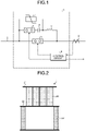
- FIG. 1 is a diagram illustrating a configuration of a direct-current circuit breaker according to a first embodiment.
- a direct-current circuit breaker 1 according to the first embodiment is a mechanical direct-current circuit breaker (DCCB) including mechanical components.
- the direct-current circuit breaker 1 is provided on a direct-current line 2 of a power system.
- the power system is a power system that performs HVDC power transmission.
- the direct-current circuit breaker 1 interrupts a direct current upon occurrence of an accident such as short-circuit or earth fault in the direct-current line 2, thereby protecting the power system.
- the direct-current circuit breaker 1 interrupts the direct current at a current zero point formed by superimposing an oscillating current on a direct current flowing through the direct-current line 2.
- the direct-current circuit breaker 1 includes: a circuit breaker 3 provided on the direct-current line 2; a capacitor 4, a reactor 5 and a high-speed switch 6 that constitute a resonance circuit; a lightning arrester 7 for suppressing an overvoltage to a voltage level based on a withstand voltage specification of a DCCB; and a control circuit 8 that controls the entirety of the direct-current circuit breaker 1.
- the capacitor 4, the reactor 5, and the high-speed switch 6 are connected in series to each other.
- the capacitor 4, the reactor 5, and the high-speed switch 6 are connected in parallel to the circuit breaker 3.
- the lightning arrester 7 is connected in parallel with the capacitor 4 and the high-speed switch 6.
- the circuit breaker 3 interrupts the direct current. That is, the circuit breaker 3 interrupts the direct current by forced extinction.
- the circuit breaker 3 is a circuit breaker capable of performing high-speed current interruption, and is, for example, a vacuum circuit breaker (VCB).
- VVB vacuum circuit breaker
- the capacitor 4 and the reactor 5 generate an oscillating current by discharging of the capacitor 4.
- the high-speed switch 6 is a switch that performs closing for forming a current zero point.
- the direct-current line 2 includes a current transformer 9 that detects an accident current which is a direct-current flowing when an accident occurs.
- the current transformer 9 outputs a detection result of the accident current to the control circuit 8.
- a device other than the current transformer 9 may be used as the device that detects the accident current.
- the control circuit 8 outputs a command for an opening operation and a command for a closing operation to each of the circuit breaker 3 and the high-speed switch 6.
- the control circuit 8 sends a signal indicating conditions of the direct-current circuit breaker 1 to a control panel which is a device outside the direct-current circuit breaker 1.
- the control panel is not illustrated.
- the destination of the signal transmitted from the control circuit 8 may be a device other than the control panel.
- the circuit breaker 3 When in a steady state, i.e., when the power system is in a steady state, the circuit breaker 3 is closed and the high-speed switch 6 is open.
- the capacitor 4 is charged by a direct-current voltage in the steady state, an external power supply, or the like.
- the circuit breaker 3 When an accident occurs, the circuit breaker 3 performs the opening operation and the high-speed switch 6 performs the closing operation.
- the high-speed switch 6 When the high-speed switch 6 is closed, electric charges from the capacitor 4 are discharged to a loop including the high-speed switch 6, the capacitor 4, the reactor 5, and the circuit breaker 3.
- an oscillating current that passes through the reactor 5, the circuit breaker 3, and the high-speed switch 6 flows from the capacitor 4.
- the direct-current circuit breaker 1 superimposes, on an accident current at the circuit breaker 3, the oscillating current in a direction opposite to the direction of the direct current, which is the accident current.
- the current zero point is formed by superimposing the oscillating current on the accident current, the extinction of arc is completed in the circuit breaker 3 during the opening operation.
- the lightning arrester 7 suppresses an overvoltage generated after the extinction of arc by the circuit breaker 3.
- FIG. 2 is a side view of the lightning arrester included in the direct-current circuit breaker according to the first embodiment.
- FIG. 3 is a top view of the lightning arrester included in the direct-current circuit breaker according to the first embodiment.
- the lightning arrester 7 includes a plurality of columns 20 arranged in an array in a horizontal direction. In the example illustrated in FIG. 3 , the lightning arrester 7 includes 12 columns 20. As the number of columns 20 constituting the lightning arrester 7, any number thereof may be employed. The plurality of columns 20 are connected in parallel to each other.
- each of the plurality of columns 20 is attached to an upper plate 21.
- a lower end of each of the plurality of columns 20 is attached to a lower plate 22.
- the plurality of columns 20 in a state of being attached to the upper plate 21 and the lower plate 22 are supported by supports 23. Below the plurality of columns 20 supported by the supports 23, a space is provided which is capable of accommodating the column 20 separated from the upper plate 21 and the lower plate 22.
- FIG. 4 is a view illustrating a schematic configuration of the column constituting the lightning arrester illustrated in FIGS. 2 and 3 .
- the column 20 includes: a stack of a plurality of nonlinear resistive elements 24; a container 25 in which the stack is accommodated; an electrode 26 on a power supply side connected to an upper end of the stack; and an electrode 27 on a ground side connected to a lower end of the stack.
- the nonlinear resistive elements 24 are each a sintered body containing zinc oxide as a main component.
- the plurality of nonlinear resistive elements 24 constituting the stack are connected in series to each other.
- the container 25 is a container made of an insulating material, and is a porcelain hollow insulator or a polymer hollow insulator.
- FIG. 4 illustrates a cross section through each of the plurality of nonlinear resistive elements 24 of the column 20.
- FIG. 5 is a diagram for explaining a process of energy performed by the lightning arrester illustrated in FIGS. 2 and 3 .
- Current I CB is a current flowing through the circuit breaker 3.
- Voltage V CB is a voltage applied to the circuit breaker 3.
- Energy E is energy processed by the lightning arrester 7.
- FIG. 5 respective changes in current I CB , voltage V CB , and energy E after the occurrence of an accident are indicated by graphs.
- a broken line indicates a current waveform in a case where the circuit breaker 3 is assumed to be in a closed state.
- Such a current waveform is a current waveform obtained by combining a direct current and a resonance current.
- the circuit breaker 3 performs the opening operation at any time between time t 1 and time t 2 .
- the high-speed switch 6 performs the closing operation.
- the direct-current circuit breaker 1 forms a current zero point by superimposing, on the accident current, an oscillating current generated in the resonance circuit by the high-speed switch 6 being closed. As a result, the direct-current circuit breaker 1 forcibly interrupts the accident current.
- the lightning arrester 7 starts processing energy from time t 3 when voltage V CB has risen to a certain voltage value.
- the lightning arrester 7 processes energy from time t 3 to time t 4 , and thereby the lightning arrester 7 suppresses an increase in voltage V CB .
- the lightning arrester 7 is designed such that a current uniformly flows to each column 20 in a period in which energy is processed.
- currents flowing through the columns 20 may vary due to a difference in characteristics such as impedance unique to each column 20.
- the number of columns 20 constituting the lightning arrester 7 increases, there is a higher possibility that the column 20 in which a magnitude of a current flowing therethrough is different from magnitudes of currents flowing through other columns 20 is included in the plurality of columns 20. Therefore, as the number of columns 20 increases, there is a higher probability that the variation in the currents flowing through the columns 20 increases.
- the allowable temperature is a maximum value of a temperature at which the column 20 can maintain a state in which energy is normally processed.
- the direct-current circuit breaker 1 monitors an anomaly in each of the plurality of columns 20 by measuring a temperature in each of the plurality of columns 20.
- the direct-current circuit breaker 1 locks the operations of the circuit breaker 3 and the high-speed switch 6, and thereby the direct-current circuit breaker 1 is stopped operating.
- the direct-current circuit breaker 1 physically separates the column 20 in which the anomaly has occurred from other columns 20.
- the direct-current circuit breaker 1 obviates a failure of the lightning arrester 7 in a case where an anomaly has occurred in one or some columns 20 out of the plurality of columns 20.
- FIG. 6 is a block diagram illustrating the control circuit included in the direct-current circuit breaker according to the first embodiment.
- FIG. 6 illustrates components of the control circuit 8 and components connected to the control circuit 8.
- the direct-current circuit breaker 1 includes: a detector 10 that detects a temperature of each column 20 provided in the lightning arrester 7; and a separator 15.
- the separator 15 is a mechanism for separating one or some columns 20 in which an anomaly has occurred from other columns 20. In FIG. 1 , illustrations of the detector 10 and the separator 15 are omitted.
- the detector 10 includes, for example, a contact type temperature sensor attached to each of the plurality of columns 20.
- the temperature sensor is attached to the container 25.
- the detector 10 may be a non-contact type temperature sensor such as a radiation thermometer or an infrared thermography device.
- the control circuit 8 includes: an operation processor 11 that controls an opening operation and a closing operation by each of the circuit breaker 3 and the high-speed switch 6; a monitor 12 that monitors the presence or absence of an anomaly in each of the plurality of columns 20; and a lock processor 13 that locks the operations of the circuit breaker 3 and the high-speed switch 6 controlled by the operation processor 11 in a case where an anomaly has occurred in at least one or some columns 20 out of the plurality of columns 20.
- the monitor 12 determines that an anomaly has occurred in one or some columns 20 having a temperature rise exceeding the allowable temperature out of the plurality of columns 20.
- the control circuit 8 further includes a communicator 14 that communicates with a device outside the direct-current circuit breaker 1.
- the detection result of the accident current obtained by the current transformer 9 is input to the operation processor 11.
- the operation processor 11 When a current exceeding a threshold which is a criterion for determination of accident current is detected in the current transformer 9, the operation processor 11 outputs a command for an opening operation to the circuit breaker 3 and outputs a command for a closing operation to the high-speed switch 6.
- the operation processor 11 instructs the communicator 14 to notify that the operation for interruption has been performed.
- the communicator 14 transmits, to the control panel, a signal indicating that the direct-current circuit breaker 1 has performed the operation for interruption.
- Detection results of temperatures obtained by the detector 10 are input to the monitor 12.
- the monitor 12 determines whether there is the column 20 of which temperature has exceeded a preset allowable temperature in the plurality of columns 20 on the basis of the detection result of the temperature of each column 20. In a case where there is the column 20 of which temperature has exceeded the allowable temperature, the monitor 12 determines that an anomaly has occurred in the column 20. When it is determined that there is the column 20 in which an anomaly has occurred, the monitor 12 outputs, to the lock processor 13, information indicating the column 20 in which the anomaly has occurred together with a determination result indicating that the anomaly has occurred.
- the lock processor 13 When the determination result indicating that the anomaly has occurred is input from the monitor 12, the lock processor 13 outputs a command for locking the operations of the circuit breaker 3 and the high-speed switch 6 to the operation processor 11.
- the operation processor 11 stops the control of the circuit breaker 3 and the high-speed switch 6 in accordance with the command from the lock processor 13.
- the direct-current circuit breaker 1 locks the operation for interruption by maintaining the circuit breaker 3 in the closed state and maintaining the high-speed switch 6 in the open state until the lock by the lock processor 13 is unlocked.
- the lock processor 13 instructs the communicator 14 to notify that the direct-current circuit breaker 1 has locked the operation for interruption.
- the communicator 14 transmits, to the control panel, a signal indicating that the direct-current circuit breaker 1 has locked the operation for interruption. While the direct-current circuit breaker 1 locks the operation for interruption, the power system is protected by a protection means other than the direct-current circuit breaker 1.
- the lock processor 13 outputs information indicating the column 20 in which the anomaly has occurred to the separator 15.
- the separator 15 separates the column 20 in which the anomaly has occurred from other columns 20 on the basis of the information from the lock processor 13.
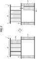
- FIG. 7 is a view for explaining an operation of the direct-current circuit breaker in a case where an anomaly has occurred in one or some of the plurality of columns constituting the lightning arrester illustrated in FIGS. 2 and 3 .
- an anomaly has occurred in a column 20a which is one of the plurality of columns 20.
- the separator 15 detaches an upper end of the column 20a from the upper plate 21 and detaches a lower end of the column 20a from the lower plate 22.
- the column 20a drops downward by gravity.
- the column 20a in which the anomaly has occurred drops downward, thereby being physically separated from other columns 20.
- the column 20a is electrically insulated from other columns 20 by being physically separated from other columns 20.
- the method of separating the column 20a from other columns 20 by the separator 15 is not limited to the method described in the first embodiment.
- the separator 15 may separate the column 20a from other columns 20 by a method other than the method in which the column 20a is dropped.
- the monitor 12 continues to acquire the detection result of the temperature of each column 20 other than the column 20a thus separated.
- the monitor 12 determines whether the temperature of each column 20 other than the column 20a out of the plurality of columns 20 has decreased to a reference temperature.
- the reference temperature is a temperature set in advance as a reference for restart of the operation by the direct-current circuit breaker 1.
- the lock processor 13 unlocks the operations of the circuit breaker 3 and the high-speed switch 6 in a case where the temperature of each column 20 has decreased to the reference temperature.
- the direct-current circuit breaker 1 may include a mechanism for making replenishment of the new column 20. In that case, the replenishment of the new column 20 is automatically performed by the mechanism regardless of the operator.
- the lock processor 13 may unlock the lock after it is confirmed that the temperature of each column 20 has decreased to the reference temperature and after the replenishment of the column 20 has been performed. The lock processor 13 may unlock the lock when it is confirmed that the temperature of each column 20 has decreased to the reference temperature regardless whether the replenishment of the column 20 has been performed or not.
- FIG. 8 is a flowchart illustrating an operation procedure of the direct-current circuit breaker according to the first embodiment.
- the detector 10 measures the temperature of each column 20 constituting the lightning arrester 7.
- the monitor 12 determines whether there is the column 20 of which temperature has exceeded the allowable temperature. If there is no column 20 of which temperature has exceeded the allowable temperature (step S2, No), the direct-current circuit breaker 1 returns the procedure to step S1.
- step S3 the lock processor 13 locks the operations of the circuit breaker 3 and the high-speed switch 6 controlled by the operation processor 11. That is, the lock processor 13 locks the operation for interruption by the direct-current circuit breaker 1.
- step S4 the separator 15 separates the column 20 in which the anomaly has occurred.
- step S5 the monitor 12 determines whether the temperature of each column 20 other than the column 20 in which the anomaly has occurred is equal to or lower than the reference temperature. If the temperature of each column 20 is not equal to or lower than the reference temperature (step S5, No), the direct-current circuit breaker 1 returns the procedure to step S5. If the temperature of each column 20 is equal to or lower than the reference temperature (step S5, Yes), in step S6, the lock processor 13 unlocks the operation for interruption by the direct-current circuit breaker 1. As a result, the direct-current circuit breaker 1 terminates the operation in accordance with the procedure illustrated in FIG. 8 .
- the monitor 12 is not limited to those monitoring the presence or absence of an anomaly on the basis of a temperature detected by the detector 10.
- the monitor 12 may monitor the presence or absence of an anomaly on the basis of a detection result of a current flowing through each of the plurality of columns 20.
- an ammeter that detects a current flowing through each of the plurality of columns 20 is used as the detector 10.
- the monitor 12 calculates a difference between a current flowing through the column 20 and a current flowing through another column 20.
- the monitor 12 determines that an anomaly that a current is concentrated has occurred in the column 20 in which the calculated difference is larger than a threshold set in advance.
- the direct-current circuit breaker 1 is not limited to a mechanical direct-current circuit breaker.
- the direct-current circuit breaker 1 may be a hybrid direct-current circuit breaker constituted by combining a mechanical component and a semiconductor component.
- the direct-current circuit breaker 1 includes: the monitor 12 that monitors the presence or absence of an anomaly in each of the plurality of columns 20; and the lock processor 13 that locks the operations of the circuit breaker 3 and the high-speed switch 6 controlled by the operation processor 11.
- the monitor 12 determines that an anomaly has occurred in one or some columns 20 having a temperature rise exceeding the allowable temperature out of the plurality of columns 20.
- the direct-current circuit breaker 1 obviates a failure of the lightning arrester 7 by locking the operation for interruption.
- the direct-current circuit breaker 1 achieves an effect that it is possible to obviate a failure of the lightning arrester 7.
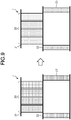
- FIG. 9 is a view for explaining an operation by the direct-current circuit breaker according to a second embodiment.
- the direct-current circuit breaker 1 according to the second embodiment has a configuration similar to that of the direct-current circuit breaker 1 according to the first embodiment.
- the direct-current circuit breaker 1 according to the second embodiment locks the operation for interruption in a case where there is an anomaly that an overall temperature of the plurality of columns 20 constituting the lightning arrester 7 rises.
- the same components as those in the first embodiment are denoted by the same reference numerals, and configurations different from those in the first embodiment will mainly be described.
- an overall temperature of the plurality of columns 20 may uniformly rise.
- the number of columns 20 connected in parallel to each other in the lightning arrester 7 is increased with respect to energy assumed to be processed in the lightning arrester 7, the number of columns 20 through which a current flows increases, and thereby it is possible to reduce the rising of the overall temperature of the plurality of columns 20.
- the increase in the number of columns 20 provided in the lightning arrester 7 leads to an increase in size of the lightning arrester 7.
- the direct-current circuit breaker 1 locks the operations of the circuit breaker 3 and the high-speed switch 6, and thereby the direct-current circuit breaker 1 is stopped operating.
- the direct-current circuit breaker 1 obviates a failure of the lightning arrester 7 due to the rising of the overall temperature of the plurality of columns 20.
- the direct-current circuit breaker 1 may not increase the number of columns 20 to be larger than the number thereof required with respect to the energy assumed to be processed.
- the monitor 12 determines whether the overall temperature of the plurality of columns 20 has risen to a first reference temperature on the basis of the detection result of the temperature of each column 20.
- the first reference temperature is a temperature set in advance as a reference for interruption of the operation of the direct-current circuit breaker 1, and is a temperature lower than the allowable temperature.
- the monitor 12 determines that an anomaly that the overall temperature of the plurality of columns 20 rises has occurred. That is, the monitor 12 determines that there is an anomaly in the entirety of the plurality of columns 20.
- the monitor 12 outputs the determination result to the lock processor 13.
- the lock processor 13 When the determination result indicating that the anomaly has occurred in the entirety of the plurality of columns 20 is input from the monitor 12, the lock processor 13 outputs a command for locking the operations of the circuit breaker 3 and the high-speed switch 6 to the operation processor 11.
- the operation processor 11 stops the control of the circuit breaker 3 and the high-speed switch 6 in accordance with the command from the lock processor 13.
- the direct-current circuit breaker 1 locks the operation for interruption by maintaining the circuit breaker 3 in the closed state and maintaining the high-speed switch 6 in the open state until the lock by the lock processor 13 is unlocked.
- the lock processor 13 instructs the communicator 14 to notify that the direct-current circuit breaker 1 has locked the operation for interruption.
- the communicator 14 transmits, to the control panel, a signal indicating that the direct-current circuit breaker 1 has locked the operation for interruption. While the direct-current circuit breaker 1 locks the operation for interruption, the power system is protected by a protection means other than the direct-current circuit breaker 1.
- the direct-current circuit breaker 1 does not separate the column 20 and waits until the temperature of the plurality of columns 20 as a whole decreases.
- the monitor 12 continues to acquire the detection result of the temperature of each of the plurality of columns 20.
- the monitor 12 determines whether the temperature of each of the plurality of columns 20 has decreased to a second reference temperature.
- the second reference temperature is a temperature set in advance as a reference for restart of the operation by the direct-current circuit breaker 1.
- the second reference temperature is the same as the reference temperature in the first embodiment.
- the lock processor 13 unlocks the operations of the circuit breaker 3 and the high-speed switch 6 in a case where the temperature of each column 20 has decreased to the second reference temperature.
- FIG. 10 is a flowchart illustrating an operation procedure of the direct-current circuit breaker according to the second embodiment.
- the detector 10 measures the temperature of each column 20 constituting the lightning arrester 7.
- the monitor 12 determines whether the overall temperature of the plurality of columns 20 has exceeded the first reference temperature. If the overall temperature of the plurality of columns 20 does not exceed the first reference temperature (step S12, No), the direct-current circuit breaker 1 returns the procedure to step S11.
- step S13 the lock processor 13 locks the operations of the circuit breaker 3 and the high-speed switch 6 controlled by the operation processor 11. That is, the lock processor 13 locks the operation for interruption by the direct-current circuit breaker 1.
- step S14 the monitor 12 determines whether the temperature of each of the plurality of columns 20 is equal to or lower than the second reference temperature. If the temperature of each of the plurality of columns 20 is not equal to or lower than the second reference temperature (step S14, No), the direct-current circuit breaker 1 returns the procedure to step S14. If the temperature of each of the plurality of columns 20 is equal to or lower than the second reference temperature (step S14, Yes), in step S15, the lock processor 13 unlocks the operation for interruption by the direct-current circuit breaker 1. As a result, the direct-current circuit breaker 1 terminates the operation in accordance with the procedure illustrated in FIG. 10 .
- the direct-current circuit breaker 1 according to the second embodiment may also perform an operation similar to that in the first embodiment in a case where there is an anomaly in one or some of the plurality of columns 20.
- the separator 15 may be omitted in a case where an operation similar to that in the first embodiment is not performed.
- the direct-current circuit breaker 1 according to the second embodiment may be either a mechanical direct-current circuit breaker or a hybrid direct-current circuit breaker.
- the direct-current circuit breaker 1 determines that there is an anomaly in the entirety of the plurality of columns 20 in a case where the overall temperature of the plurality of columns 20 has risen to the first reference temperature.
- the direct-current circuit breaker 1 can lock the operation for interruption.
- the direct-current circuit breaker 1 can obviate a failure of the lightning arrester 7 due to the rising of the overall temperature of the plurality of columns 20.
- the direct-current circuit breaker 1 there is no need to increase the number of columns 20 with respect to the energy assumed to be processed, and therefore it is possible to suppress an increase in size of the lightning arrester 7.
- control circuit 8 included in the direct-current circuit breaker 1 according to the first and second embodiments.
- a function of the control circuit 8 is realized using a processing circuitry.
- the processing circuitry is a processor that executes a program stored in a memory.
- the processing circuitry may be dedicated hardware mounted on the direct-current circuit breaker 1.
- FIG. 11 is a first diagram illustrating an example of a hardware configuration of the control circuit included in the direct-current circuit breaker according to the first or second embodiment.
- FIG. 11 illustrates a hardware configuration in a case where the function of the control circuit 8 is realized by using hardware that executes a program.
- a processor 31, a memory 32, and an interface 33 are connected to each other via a bus.
- the processor 31 is a central processing unit (CPU), a processing device, an arithmetic device, a microprocessor, a microcomputer, or a digital signal processor (DSP). Functions of the operation processor 11, the monitor 12, and the lock processor 13 are realized by the processor 31, and software, firmware, or a combination of software and firmware.
- the software or the firmware is written as a program and stored in the memory 32 as a built-in memory.
- the memory 32 is a nonvolatile or volatile semiconductor memory, and is a random access memory (RAM), a read only memory (ROM), a flash memory, an erasable programmable read only memory (EPROM), or an electrically erasable programmable read only memory (EEPROM (registered trademark)).
- the interface 33 is responsible for signal input and signal output.
- the communicator 14 is realized by using the interface 33.
- the interface 33 outputs a command to each of the circuit breaker 3 and the high-speed switch 6.
- a signal indicating a detection result of a direct current obtained by the current transformer 9 is input to the interface 33.
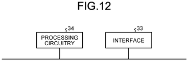
- FIG. 12 is a second diagram illustrating an example of the hardware configuration of the control circuit included in the direct-current circuit breaker according to the first or second embodiment.
- FIG. 12 illustrates a hardware configuration in a case where the function of the control circuit 8 is realized by using dedicated hardware.
- the control circuit 8 includes a processing circuitry 34 that executes various processes and the interface 33 similar to that in FIG. 11 .
- the processing circuitry 34 and the interface 33 are connected to each other via a bus.
- the processing circuitry 34 as dedicated hardware is a single circuit, a composite circuit, a programmed processor, a parallel programmed processor, an application specific integrated circuit (ASIC), a field-programmable gate array (FPGA), or a combination thereof.
- the function of the control circuit 8 is realized by using the processing circuitry 34.
Landscapes
- Engineering & Computer Science (AREA)
- Power Engineering (AREA)
- Driving Mechanisms And Operating Circuits Of Arc-Extinguishing High-Tension Switches (AREA)
- Emergency Protection Circuit Devices (AREA)
Applications Claiming Priority (1)
| Application Number | Priority Date | Filing Date | Title |
|---|---|---|---|
| PCT/JP2020/001965 WO2021149158A1 (ja) | 2020-01-21 | 2020-01-21 | 直流遮断器 |
Publications (3)
| Publication Number | Publication Date |
|---|---|
| EP4095877A1 true EP4095877A1 (de) | 2022-11-30 |
| EP4095877A4 EP4095877A4 (de) | 2023-03-22 |
| EP4095877B1 EP4095877B1 (de) | 2025-07-23 |
Family
ID=72517842
Family Applications (1)
| Application Number | Title | Priority Date | Filing Date |
|---|---|---|---|
| EP20916137.1A Active EP4095877B1 (de) | 2020-01-21 | 2020-01-21 | Gleichstromschutzschalter |
Country Status (3)
| Country | Link |
|---|---|
| EP (1) | EP4095877B1 (de) |
| JP (1) | JP6758554B1 (de) |
| WO (1) | WO2021149158A1 (de) |
Cited By (1)
| Publication number | Priority date | Publication date | Assignee | Title |
|---|---|---|---|---|
| CN116666021A (zh) * | 2023-05-23 | 2023-08-29 | 国网电力科学研究院武汉南瑞有限责任公司 | 一种±500kV直流断路器能量吸收用避雷器及其设计方法 |
Families Citing this family (1)
| Publication number | Priority date | Publication date | Assignee | Title |
|---|---|---|---|---|
| CN116660792A (zh) * | 2023-06-29 | 2023-08-29 | 泉州维盾电气有限公司 | 一种带避雷设备健康监测功能的磁控支柱式断路器结构 |
Family Cites Families (3)
| Publication number | Priority date | Publication date | Assignee | Title |
|---|---|---|---|---|
| JPS56158642U (de) * | 1980-04-28 | 1981-11-26 | ||
| JPS59163722A (ja) | 1983-03-07 | 1984-09-14 | 三菱電機株式会社 | 直流しや断装置 |
| JP6328356B1 (ja) * | 2017-07-11 | 2018-05-23 | 三菱電機株式会社 | 直流遮断器 |
-
2020
- 2020-01-21 JP JP2020535160A patent/JP6758554B1/ja active Active
- 2020-01-21 EP EP20916137.1A patent/EP4095877B1/de active Active
- 2020-01-21 WO PCT/JP2020/001965 patent/WO2021149158A1/ja not_active Ceased
Cited By (1)
| Publication number | Priority date | Publication date | Assignee | Title |
|---|---|---|---|---|
| CN116666021A (zh) * | 2023-05-23 | 2023-08-29 | 国网电力科学研究院武汉南瑞有限责任公司 | 一种±500kV直流断路器能量吸收用避雷器及其设计方法 |
Also Published As
| Publication number | Publication date |
|---|---|
| JP6758554B1 (ja) | 2020-09-23 |
| EP4095877B1 (de) | 2025-07-23 |
| EP4095877A4 (de) | 2023-03-22 |
| JPWO2021149158A1 (de) | 2021-07-29 |
| WO2021149158A1 (ja) | 2021-07-29 |
Similar Documents
| Publication | Publication Date | Title |
|---|---|---|
| JP4679675B1 (ja) | 電力変換装置 | |
| US8995097B2 (en) | High voltage DC breaker apparatus | |
| KR102862516B1 (ko) | 향상된 안전성 지능을 갖는 위험 위치 순응성 회로 보호 디바이스들, 시스템들, 및 방법들 | |
| EP3002850B1 (de) | Überladungsschutzvorrichtung und verfahren mit diagnosefunktion | |
| EP4095877A1 (de) | Gleichstromschutzschalter | |
| JP5990878B2 (ja) | 無停電電源装置及び電源装置 | |
| EP2608341A1 (de) | Erdungsvorrichtung | |
| WO2012084693A1 (en) | Method, circuit breaker and switching unit for switching off high-voltage dc currents | |
| JP5743913B2 (ja) | 電力変換装置 | |
| EP4261865B1 (de) | Gleichstromschutzschalter und gleichstromschutzschaltersystem | |
| US8319377B2 (en) | Fuse for disconnecting an inverter from a photovoltaic generator | |
| US10312851B2 (en) | Motor drive having function for preventing secondary damage | |
| US20260074539A1 (en) | Battery control device and short-circuit detection method thereof | |
| EP4401283A1 (de) | Elektrolysesystem und betriebsverfahren dafür | |
| KR102632405B1 (ko) | 고장전류 저감회로를 포함하는 집합전지 시스템 | |
| KR101729399B1 (ko) | 전류식 직류 차단기 및 그 감시 방법 | |
| EP3783634B1 (de) | Gleichstromschutzschalter | |
| CN109842097B (zh) | 电子保护电路 | |
| EP3391489B1 (de) | Erdschlussdetektions- und schutzschaltungssystem | |
| WO2018091138A1 (de) | Leistungselektronik mit trennsicherung | |
| AU2020276834B2 (en) | Thyristor circuit and thyristor protection method | |
| KR20220083927A (ko) | 배터리 화재방지를 위한 최대 허용 병렬 연결수를 적용한 배터리 랙 설계 방법, 배터리 적합성 점검 방법, 배터리 랙 시험 장치 및 배터리 랙 | |
| JP2020167770A (ja) | バッテリモジュール、バッテリモジュールの運用方法 | |
| EP3413378A1 (de) | Batteriesystem | |
| KR20150094541A (ko) | 전기 과부하 검출 장치 |
Legal Events
| Date | Code | Title | Description |
|---|---|---|---|
| STAA | Information on the status of an ep patent application or granted ep patent |
Free format text: STATUS: THE INTERNATIONAL PUBLICATION HAS BEEN MADE |
|
| PUAI | Public reference made under article 153(3) epc to a published international application that has entered the european phase |
Free format text: ORIGINAL CODE: 0009012 |
|
| STAA | Information on the status of an ep patent application or granted ep patent |
Free format text: STATUS: REQUEST FOR EXAMINATION WAS MADE |
|
| 17P | Request for examination filed |
Effective date: 20220705 |
|
| AK | Designated contracting states |
Kind code of ref document: A1 Designated state(s): AL AT BE BG CH CY CZ DE DK EE ES FI FR GB GR HR HU IE IS IT LI LT LU LV MC MK MT NL NO PL PT RO RS SE SI SK SM TR |
|
| A4 | Supplementary search report drawn up and despatched |
Effective date: 20230222 |
|
| RIC1 | Information provided on ipc code assigned before grant |
Ipc: H01H 33/59 20060101AFI20230216BHEP |
|
| DAV | Request for validation of the european patent (deleted) | ||
| DAX | Request for extension of the european patent (deleted) | ||
| GRAP | Despatch of communication of intention to grant a patent |
Free format text: ORIGINAL CODE: EPIDOSNIGR1 |
|
| STAA | Information on the status of an ep patent application or granted ep patent |
Free format text: STATUS: GRANT OF PATENT IS INTENDED |
|
| INTG | Intention to grant announced |
Effective date: 20250219 |
|
| GRAS | Grant fee paid |
Free format text: ORIGINAL CODE: EPIDOSNIGR3 |
|
| GRAA | (expected) grant |
Free format text: ORIGINAL CODE: 0009210 |
|
| STAA | Information on the status of an ep patent application or granted ep patent |
Free format text: STATUS: THE PATENT HAS BEEN GRANTED |
|
| AK | Designated contracting states |
Kind code of ref document: B1 Designated state(s): AL AT BE BG CH CY CZ DE DK EE ES FI FR GB GR HR HU IE IS IT LI LT LU LV MC MK MT NL NO PL PT RO RS SE SI SK SM TR |
|
| REG | Reference to a national code |
Ref country code: GB Ref legal event code: FG4D |
|
| REG | Reference to a national code |
Ref country code: CH Ref legal event code: EP |
|
| REG | Reference to a national code |
Ref country code: IE Ref legal event code: FG4D |
|
| REG | Reference to a national code |
Ref country code: DE Ref legal event code: R096 Ref document number: 602020055242 Country of ref document: DE |
|
| REG | Reference to a national code |
Ref country code: SE Ref legal event code: TRGR |
|
| REG | Reference to a national code |
Ref country code: NL Ref legal event code: MP Effective date: 20250723 |
|
| PG25 | Lapsed in a contracting state [announced via postgrant information from national office to epo] |
Ref country code: PT Free format text: LAPSE BECAUSE OF FAILURE TO SUBMIT A TRANSLATION OF THE DESCRIPTION OR TO PAY THE FEE WITHIN THE PRESCRIBED TIME-LIMIT Effective date: 20251124 |
|
| PG25 | Lapsed in a contracting state [announced via postgrant information from national office to epo] |
Ref country code: NL Free format text: LAPSE BECAUSE OF FAILURE TO SUBMIT A TRANSLATION OF THE DESCRIPTION OR TO PAY THE FEE WITHIN THE PRESCRIBED TIME-LIMIT Effective date: 20250723 |
|
| REG | Reference to a national code |
Ref country code: AT Ref legal event code: MK05 Ref document number: 1817346 Country of ref document: AT Kind code of ref document: T Effective date: 20250723 |
|
| PG25 | Lapsed in a contracting state [announced via postgrant information from national office to epo] |
Ref country code: IS Free format text: LAPSE BECAUSE OF FAILURE TO SUBMIT A TRANSLATION OF THE DESCRIPTION OR TO PAY THE FEE WITHIN THE PRESCRIBED TIME-LIMIT Effective date: 20251123 |
|
| PG25 | Lapsed in a contracting state [announced via postgrant information from national office to epo] |
Ref country code: NO Free format text: LAPSE BECAUSE OF FAILURE TO SUBMIT A TRANSLATION OF THE DESCRIPTION OR TO PAY THE FEE WITHIN THE PRESCRIBED TIME-LIMIT Effective date: 20251023 |
|
| REG | Reference to a national code |
Ref country code: LT Ref legal event code: MG9D |
|
| PG25 | Lapsed in a contracting state [announced via postgrant information from national office to epo] |
Ref country code: AT Free format text: LAPSE BECAUSE OF FAILURE TO SUBMIT A TRANSLATION OF THE DESCRIPTION OR TO PAY THE FEE WITHIN THE PRESCRIBED TIME-LIMIT Effective date: 20250723 |
|
| PG25 | Lapsed in a contracting state [announced via postgrant information from national office to epo] |
Ref country code: FI Free format text: LAPSE BECAUSE OF FAILURE TO SUBMIT A TRANSLATION OF THE DESCRIPTION OR TO PAY THE FEE WITHIN THE PRESCRIBED TIME-LIMIT Effective date: 20250723 |
|
| PG25 | Lapsed in a contracting state [announced via postgrant information from national office to epo] |
Ref country code: HR Free format text: LAPSE BECAUSE OF FAILURE TO SUBMIT A TRANSLATION OF THE DESCRIPTION OR TO PAY THE FEE WITHIN THE PRESCRIBED TIME-LIMIT Effective date: 20250723 |
|
| PG25 | Lapsed in a contracting state [announced via postgrant information from national office to epo] |
Ref country code: GR Free format text: LAPSE BECAUSE OF FAILURE TO SUBMIT A TRANSLATION OF THE DESCRIPTION OR TO PAY THE FEE WITHIN THE PRESCRIBED TIME-LIMIT Effective date: 20251024 |
|
| PGFP | Annual fee paid to national office [announced via postgrant information from national office to epo] |
Ref country code: SE Payment date: 20251210 Year of fee payment: 7 |
|
| PG25 | Lapsed in a contracting state [announced via postgrant information from national office to epo] |
Ref country code: LV Free format text: LAPSE BECAUSE OF FAILURE TO SUBMIT A TRANSLATION OF THE DESCRIPTION OR TO PAY THE FEE WITHIN THE PRESCRIBED TIME-LIMIT Effective date: 20250723 |
|
| PG25 | Lapsed in a contracting state [announced via postgrant information from national office to epo] |
Ref country code: PL Free format text: LAPSE BECAUSE OF FAILURE TO SUBMIT A TRANSLATION OF THE DESCRIPTION OR TO PAY THE FEE WITHIN THE PRESCRIBED TIME-LIMIT Effective date: 20250723 Ref country code: BG Free format text: LAPSE BECAUSE OF FAILURE TO SUBMIT A TRANSLATION OF THE DESCRIPTION OR TO PAY THE FEE WITHIN THE PRESCRIBED TIME-LIMIT Effective date: 20250723 |
|
| PG25 | Lapsed in a contracting state [announced via postgrant information from national office to epo] |
Ref country code: RS Free format text: LAPSE BECAUSE OF FAILURE TO SUBMIT A TRANSLATION OF THE DESCRIPTION OR TO PAY THE FEE WITHIN THE PRESCRIBED TIME-LIMIT Effective date: 20251023 |
|
| PG25 | Lapsed in a contracting state [announced via postgrant information from national office to epo] |
Ref country code: ES Free format text: LAPSE BECAUSE OF FAILURE TO SUBMIT A TRANSLATION OF THE DESCRIPTION OR TO PAY THE FEE WITHIN THE PRESCRIBED TIME-LIMIT Effective date: 20250723 |
|
| PG25 | Lapsed in a contracting state [announced via postgrant information from national office to epo] |
Ref country code: SM Free format text: LAPSE BECAUSE OF FAILURE TO SUBMIT A TRANSLATION OF THE DESCRIPTION OR TO PAY THE FEE WITHIN THE PRESCRIBED TIME-LIMIT Effective date: 20250723 |
|
| PG25 | Lapsed in a contracting state [announced via postgrant information from national office to epo] |
Ref country code: DK Free format text: LAPSE BECAUSE OF FAILURE TO SUBMIT A TRANSLATION OF THE DESCRIPTION OR TO PAY THE FEE WITHIN THE PRESCRIBED TIME-LIMIT Effective date: 20250723 |
|
| PGFP | Annual fee paid to national office [announced via postgrant information from national office to epo] |
Ref country code: DE Payment date: 20251203 Year of fee payment: 7 |
|
| PG25 | Lapsed in a contracting state [announced via postgrant information from national office to epo] |
Ref country code: IT Free format text: LAPSE BECAUSE OF FAILURE TO SUBMIT A TRANSLATION OF THE DESCRIPTION OR TO PAY THE FEE WITHIN THE PRESCRIBED TIME-LIMIT Effective date: 20250723 |