EP4095005A1 - Vehicle braking system - Google Patents
Vehicle braking system Download PDFInfo
- Publication number
- EP4095005A1 EP4095005A1 EP21175737.2A EP21175737A EP4095005A1 EP 4095005 A1 EP4095005 A1 EP 4095005A1 EP 21175737 A EP21175737 A EP 21175737A EP 4095005 A1 EP4095005 A1 EP 4095005A1
- Authority
- EP
- European Patent Office
- Prior art keywords
- master cylinder
- pressure
- brake
- operated
- brake pedal
- Prior art date
- Legal status (The legal status is an assumption and is not a legal conclusion. Google has not performed a legal analysis and makes no representation as to the accuracy of the status listed.)
- Pending
Links
Images


Classifications
-
- B—PERFORMING OPERATIONS; TRANSPORTING
- B60—VEHICLES IN GENERAL
- B60T—VEHICLE BRAKE CONTROL SYSTEMS OR PARTS THEREOF; BRAKE CONTROL SYSTEMS OR PARTS THEREOF, IN GENERAL; ARRANGEMENT OF BRAKING ELEMENTS ON VEHICLES IN GENERAL; PORTABLE DEVICES FOR PREVENTING UNWANTED MOVEMENT OF VEHICLES; VEHICLE MODIFICATIONS TO FACILITATE COOLING OF BRAKES
- B60T8/00—Arrangements for adjusting wheel-braking force to meet varying vehicular or ground-surface conditions, e.g. limiting or varying distribution of braking force
- B60T8/32—Arrangements for adjusting wheel-braking force to meet varying vehicular or ground-surface conditions, e.g. limiting or varying distribution of braking force responsive to a speed condition, e.g. acceleration or deceleration
- B60T8/34—Arrangements for adjusting wheel-braking force to meet varying vehicular or ground-surface conditions, e.g. limiting or varying distribution of braking force responsive to a speed condition, e.g. acceleration or deceleration having a fluid pressure regulator responsive to a speed condition
- B60T8/44—Arrangements for adjusting wheel-braking force to meet varying vehicular or ground-surface conditions, e.g. limiting or varying distribution of braking force responsive to a speed condition, e.g. acceleration or deceleration having a fluid pressure regulator responsive to a speed condition co-operating with a power-assist booster means associated with a master cylinder for controlling the release and reapplication of brake pressure through an interaction with the power assist device, i.e. open systems
- B60T8/445—Arrangements for adjusting wheel-braking force to meet varying vehicular or ground-surface conditions, e.g. limiting or varying distribution of braking force responsive to a speed condition, e.g. acceleration or deceleration having a fluid pressure regulator responsive to a speed condition co-operating with a power-assist booster means associated with a master cylinder for controlling the release and reapplication of brake pressure through an interaction with the power assist device, i.e. open systems replenishing the released brake fluid volume into the brake piping
-
- B—PERFORMING OPERATIONS; TRANSPORTING
- B60—VEHICLES IN GENERAL
- B60T—VEHICLE BRAKE CONTROL SYSTEMS OR PARTS THEREOF; BRAKE CONTROL SYSTEMS OR PARTS THEREOF, IN GENERAL; ARRANGEMENT OF BRAKING ELEMENTS ON VEHICLES IN GENERAL; PORTABLE DEVICES FOR PREVENTING UNWANTED MOVEMENT OF VEHICLES; VEHICLE MODIFICATIONS TO FACILITATE COOLING OF BRAKES
- B60T13/00—Transmitting braking action from initiating means to ultimate brake actuator with power assistance or drive; Brake systems incorporating such transmitting means, e.g. air-pressure brake systems
- B60T13/10—Transmitting braking action from initiating means to ultimate brake actuator with power assistance or drive; Brake systems incorporating such transmitting means, e.g. air-pressure brake systems with fluid assistance, drive, or release
- B60T13/12—Transmitting braking action from initiating means to ultimate brake actuator with power assistance or drive; Brake systems incorporating such transmitting means, e.g. air-pressure brake systems with fluid assistance, drive, or release the fluid being liquid
- B60T13/14—Transmitting braking action from initiating means to ultimate brake actuator with power assistance or drive; Brake systems incorporating such transmitting means, e.g. air-pressure brake systems with fluid assistance, drive, or release the fluid being liquid using accumulators or reservoirs fed by pumps
- B60T13/142—Systems with master cylinder
- B60T13/147—In combination with distributor valve
-
- B—PERFORMING OPERATIONS; TRANSPORTING
- B60—VEHICLES IN GENERAL
- B60T—VEHICLE BRAKE CONTROL SYSTEMS OR PARTS THEREOF; BRAKE CONTROL SYSTEMS OR PARTS THEREOF, IN GENERAL; ARRANGEMENT OF BRAKING ELEMENTS ON VEHICLES IN GENERAL; PORTABLE DEVICES FOR PREVENTING UNWANTED MOVEMENT OF VEHICLES; VEHICLE MODIFICATIONS TO FACILITATE COOLING OF BRAKES
- B60T7/00—Brake-action initiating means
- B60T7/02—Brake-action initiating means for personal initiation
- B60T7/04—Brake-action initiating means for personal initiation foot actuated
- B60T7/042—Brake-action initiating means for personal initiation foot actuated by electrical means, e.g. using travel or force sensors
-
- B—PERFORMING OPERATIONS; TRANSPORTING
- B60—VEHICLES IN GENERAL
- B60T—VEHICLE BRAKE CONTROL SYSTEMS OR PARTS THEREOF; BRAKE CONTROL SYSTEMS OR PARTS THEREOF, IN GENERAL; ARRANGEMENT OF BRAKING ELEMENTS ON VEHICLES IN GENERAL; PORTABLE DEVICES FOR PREVENTING UNWANTED MOVEMENT OF VEHICLES; VEHICLE MODIFICATIONS TO FACILITATE COOLING OF BRAKES
- B60T13/00—Transmitting braking action from initiating means to ultimate brake actuator with power assistance or drive; Brake systems incorporating such transmitting means, e.g. air-pressure brake systems
- B60T13/10—Transmitting braking action from initiating means to ultimate brake actuator with power assistance or drive; Brake systems incorporating such transmitting means, e.g. air-pressure brake systems with fluid assistance, drive, or release
- B60T13/12—Transmitting braking action from initiating means to ultimate brake actuator with power assistance or drive; Brake systems incorporating such transmitting means, e.g. air-pressure brake systems with fluid assistance, drive, or release the fluid being liquid
- B60T13/14—Transmitting braking action from initiating means to ultimate brake actuator with power assistance or drive; Brake systems incorporating such transmitting means, e.g. air-pressure brake systems with fluid assistance, drive, or release the fluid being liquid using accumulators or reservoirs fed by pumps
- B60T13/142—Systems with master cylinder
- B60T13/145—Master cylinder integrated or hydraulically coupled with booster
-
- B—PERFORMING OPERATIONS; TRANSPORTING
- B60—VEHICLES IN GENERAL
- B60T—VEHICLE BRAKE CONTROL SYSTEMS OR PARTS THEREOF; BRAKE CONTROL SYSTEMS OR PARTS THEREOF, IN GENERAL; ARRANGEMENT OF BRAKING ELEMENTS ON VEHICLES IN GENERAL; PORTABLE DEVICES FOR PREVENTING UNWANTED MOVEMENT OF VEHICLES; VEHICLE MODIFICATIONS TO FACILITATE COOLING OF BRAKES
- B60T13/00—Transmitting braking action from initiating means to ultimate brake actuator with power assistance or drive; Brake systems incorporating such transmitting means, e.g. air-pressure brake systems
- B60T13/10—Transmitting braking action from initiating means to ultimate brake actuator with power assistance or drive; Brake systems incorporating such transmitting means, e.g. air-pressure brake systems with fluid assistance, drive, or release
- B60T13/66—Electrical control in fluid-pressure brake systems
- B60T13/68—Electrical control in fluid-pressure brake systems by electrically-controlled valves
- B60T13/686—Electrical control in fluid-pressure brake systems by electrically-controlled valves in hydraulic systems or parts thereof
-
- B—PERFORMING OPERATIONS; TRANSPORTING
- B60—VEHICLES IN GENERAL
- B60T—VEHICLE BRAKE CONTROL SYSTEMS OR PARTS THEREOF; BRAKE CONTROL SYSTEMS OR PARTS THEREOF, IN GENERAL; ARRANGEMENT OF BRAKING ELEMENTS ON VEHICLES IN GENERAL; PORTABLE DEVICES FOR PREVENTING UNWANTED MOVEMENT OF VEHICLES; VEHICLE MODIFICATIONS TO FACILITATE COOLING OF BRAKES
- B60T13/00—Transmitting braking action from initiating means to ultimate brake actuator with power assistance or drive; Brake systems incorporating such transmitting means, e.g. air-pressure brake systems
- B60T13/74—Transmitting braking action from initiating means to ultimate brake actuator with power assistance or drive; Brake systems incorporating such transmitting means, e.g. air-pressure brake systems with electrical assistance or drive
- B60T13/745—Transmitting braking action from initiating means to ultimate brake actuator with power assistance or drive; Brake systems incorporating such transmitting means, e.g. air-pressure brake systems with electrical assistance or drive acting on a hydraulic system, e.g. a master cylinder
-
- B—PERFORMING OPERATIONS; TRANSPORTING
- B60—VEHICLES IN GENERAL
- B60T—VEHICLE BRAKE CONTROL SYSTEMS OR PARTS THEREOF; BRAKE CONTROL SYSTEMS OR PARTS THEREOF, IN GENERAL; ARRANGEMENT OF BRAKING ELEMENTS ON VEHICLES IN GENERAL; PORTABLE DEVICES FOR PREVENTING UNWANTED MOVEMENT OF VEHICLES; VEHICLE MODIFICATIONS TO FACILITATE COOLING OF BRAKES
- B60T7/00—Brake-action initiating means
- B60T7/02—Brake-action initiating means for personal initiation
- B60T7/04—Brake-action initiating means for personal initiation foot actuated
-
- B—PERFORMING OPERATIONS; TRANSPORTING
- B60—VEHICLES IN GENERAL
- B60T—VEHICLE BRAKE CONTROL SYSTEMS OR PARTS THEREOF; BRAKE CONTROL SYSTEMS OR PARTS THEREOF, IN GENERAL; ARRANGEMENT OF BRAKING ELEMENTS ON VEHICLES IN GENERAL; PORTABLE DEVICES FOR PREVENTING UNWANTED MOVEMENT OF VEHICLES; VEHICLE MODIFICATIONS TO FACILITATE COOLING OF BRAKES
- B60T8/00—Arrangements for adjusting wheel-braking force to meet varying vehicular or ground-surface conditions, e.g. limiting or varying distribution of braking force
- B60T8/17—Using electrical or electronic regulation means to control braking
- B60T8/1755—Brake regulation specially adapted to control the stability of the vehicle, e.g. taking into account yaw rate or transverse acceleration in a curve
-
- B—PERFORMING OPERATIONS; TRANSPORTING
- B60—VEHICLES IN GENERAL
- B60T—VEHICLE BRAKE CONTROL SYSTEMS OR PARTS THEREOF; BRAKE CONTROL SYSTEMS OR PARTS THEREOF, IN GENERAL; ARRANGEMENT OF BRAKING ELEMENTS ON VEHICLES IN GENERAL; PORTABLE DEVICES FOR PREVENTING UNWANTED MOVEMENT OF VEHICLES; VEHICLE MODIFICATIONS TO FACILITATE COOLING OF BRAKES
- B60T8/00—Arrangements for adjusting wheel-braking force to meet varying vehicular or ground-surface conditions, e.g. limiting or varying distribution of braking force
- B60T8/32—Arrangements for adjusting wheel-braking force to meet varying vehicular or ground-surface conditions, e.g. limiting or varying distribution of braking force responsive to a speed condition, e.g. acceleration or deceleration
- B60T8/321—Arrangements for adjusting wheel-braking force to meet varying vehicular or ground-surface conditions, e.g. limiting or varying distribution of braking force responsive to a speed condition, e.g. acceleration or deceleration deceleration
- B60T8/3255—Systems in which the braking action is dependent on brake pedal data
- B60T8/326—Hydraulic systems
-
- B—PERFORMING OPERATIONS; TRANSPORTING
- B60—VEHICLES IN GENERAL
- B60T—VEHICLE BRAKE CONTROL SYSTEMS OR PARTS THEREOF; BRAKE CONTROL SYSTEMS OR PARTS THEREOF, IN GENERAL; ARRANGEMENT OF BRAKING ELEMENTS ON VEHICLES IN GENERAL; PORTABLE DEVICES FOR PREVENTING UNWANTED MOVEMENT OF VEHICLES; VEHICLE MODIFICATIONS TO FACILITATE COOLING OF BRAKES
- B60T8/00—Arrangements for adjusting wheel-braking force to meet varying vehicular or ground-surface conditions, e.g. limiting or varying distribution of braking force
- B60T8/32—Arrangements for adjusting wheel-braking force to meet varying vehicular or ground-surface conditions, e.g. limiting or varying distribution of braking force responsive to a speed condition, e.g. acceleration or deceleration
- B60T8/34—Arrangements for adjusting wheel-braking force to meet varying vehicular or ground-surface conditions, e.g. limiting or varying distribution of braking force responsive to a speed condition, e.g. acceleration or deceleration having a fluid pressure regulator responsive to a speed condition
- B60T8/36—Arrangements for adjusting wheel-braking force to meet varying vehicular or ground-surface conditions, e.g. limiting or varying distribution of braking force responsive to a speed condition, e.g. acceleration or deceleration having a fluid pressure regulator responsive to a speed condition including a pilot valve responding to an electromagnetic force
- B60T8/3615—Electromagnetic valves specially adapted for anti-lock brake and traction control systems
- B60T8/3675—Electromagnetic valves specially adapted for anti-lock brake and traction control systems integrated in modulator units
- B60T8/368—Electromagnetic valves specially adapted for anti-lock brake and traction control systems integrated in modulator units combined with other mechanical components, e.g. pump units, master cylinders
-
- B—PERFORMING OPERATIONS; TRANSPORTING
- B60—VEHICLES IN GENERAL
- B60T—VEHICLE BRAKE CONTROL SYSTEMS OR PARTS THEREOF; BRAKE CONTROL SYSTEMS OR PARTS THEREOF, IN GENERAL; ARRANGEMENT OF BRAKING ELEMENTS ON VEHICLES IN GENERAL; PORTABLE DEVICES FOR PREVENTING UNWANTED MOVEMENT OF VEHICLES; VEHICLE MODIFICATIONS TO FACILITATE COOLING OF BRAKES
- B60T8/00—Arrangements for adjusting wheel-braking force to meet varying vehicular or ground-surface conditions, e.g. limiting or varying distribution of braking force
- B60T8/32—Arrangements for adjusting wheel-braking force to meet varying vehicular or ground-surface conditions, e.g. limiting or varying distribution of braking force responsive to a speed condition, e.g. acceleration or deceleration
- B60T8/34—Arrangements for adjusting wheel-braking force to meet varying vehicular or ground-surface conditions, e.g. limiting or varying distribution of braking force responsive to a speed condition, e.g. acceleration or deceleration having a fluid pressure regulator responsive to a speed condition
- B60T8/40—Arrangements for adjusting wheel-braking force to meet varying vehicular or ground-surface conditions, e.g. limiting or varying distribution of braking force responsive to a speed condition, e.g. acceleration or deceleration having a fluid pressure regulator responsive to a speed condition comprising an additional fluid circuit including fluid pressurising means for modifying the pressure of the braking fluid, e.g. including wheel driven pumps for detecting a speed condition, or pumps which are controlled by means independent of the braking system
- B60T8/4072—Systems in which a driver input signal is used as a control signal for the additional fluid circuit which is normally used for braking
- B60T8/4081—Systems with stroke simulating devices for driver input
- B60T8/409—Systems with stroke simulating devices for driver input characterised by details of the stroke simulating device
-
- B—PERFORMING OPERATIONS; TRANSPORTING
- B60—VEHICLES IN GENERAL
- B60T—VEHICLE BRAKE CONTROL SYSTEMS OR PARTS THEREOF; BRAKE CONTROL SYSTEMS OR PARTS THEREOF, IN GENERAL; ARRANGEMENT OF BRAKING ELEMENTS ON VEHICLES IN GENERAL; PORTABLE DEVICES FOR PREVENTING UNWANTED MOVEMENT OF VEHICLES; VEHICLE MODIFICATIONS TO FACILITATE COOLING OF BRAKES
- B60T8/00—Arrangements for adjusting wheel-braking force to meet varying vehicular or ground-surface conditions, e.g. limiting or varying distribution of braking force
- B60T8/32—Arrangements for adjusting wheel-braking force to meet varying vehicular or ground-surface conditions, e.g. limiting or varying distribution of braking force responsive to a speed condition, e.g. acceleration or deceleration
- B60T8/34—Arrangements for adjusting wheel-braking force to meet varying vehicular or ground-surface conditions, e.g. limiting or varying distribution of braking force responsive to a speed condition, e.g. acceleration or deceleration having a fluid pressure regulator responsive to a speed condition
- B60T8/48—Arrangements for adjusting wheel-braking force to meet varying vehicular or ground-surface conditions, e.g. limiting or varying distribution of braking force responsive to a speed condition, e.g. acceleration or deceleration having a fluid pressure regulator responsive to a speed condition connecting the brake actuator to an alternative or additional source of fluid pressure, e.g. traction control systems
- B60T8/4809—Traction control, stability control, using both the wheel brakes and other automatic braking systems
- B60T8/4827—Traction control, stability control, using both the wheel brakes and other automatic braking systems in hydraulic brake systems
- B60T8/4845—Traction control, stability control, using both the wheel brakes and other automatic braking systems in hydraulic brake systems using a booster or a master cylinder for traction control
-
- B—PERFORMING OPERATIONS; TRANSPORTING
- B60—VEHICLES IN GENERAL
- B60T—VEHICLE BRAKE CONTROL SYSTEMS OR PARTS THEREOF; BRAKE CONTROL SYSTEMS OR PARTS THEREOF, IN GENERAL; ARRANGEMENT OF BRAKING ELEMENTS ON VEHICLES IN GENERAL; PORTABLE DEVICES FOR PREVENTING UNWANTED MOVEMENT OF VEHICLES; VEHICLE MODIFICATIONS TO FACILITATE COOLING OF BRAKES
- B60T2270/00—Further aspects of brake control systems not otherwise provided for
- B60T2270/82—Brake-by-Wire, EHB
Definitions
- the present invention relates to braking systems for vehicles, of the type comprising a master cylinder including at least one pumping piston operatively connected to a brake pedal, and configured to supply pressurized fluid to a delivery line of the master cylinder, following an actuation of the brake pedal, so as to cause the activation of a hydraulically-operated brake device associated with a respective wheel of the vehicle.
- a vacuum-operated assisting device is associated with the master cylinder, the assisting device being connected to a vacuum source, for example the intake manifold of the internal combustion engine of the motor-vehicle.
- a first object of the present invention is to provide a braking system that does not require a vacuum-operated assisting device and that is therefore suitable for installation on electrically-powered or hybrid vehicles, as well as on conventional vehicles with internal combustion engines.
- An additional object of the invention is to control the "feeling" on the brake pedal, i.e., the force that opposes the actuation of the brake pedal, in a manner completely independent from the pressure in the hydraulic line for actuating the brake device.
- An additional object of the invention is to provide a braking system that is capable of operating either in a basic operating mode in which the brake device is operated only by the fluid pressure generated by the master cylinder, or in an assisted-braking operating manner, in which the brake device is actuated not only by the fluid pressure generated by the master cylinder, but also by fluid pressure generated by an electrically-operated pressure source, or in an operating mode in which the brake device is operated only by the fluid pressure generated by said electrically-operated pressure source, according to a Brake-by-Wire (BBW) mode.
- BBW Brake-by-Wire
- An additional object of the invention is to provide a braking system of the type indicated above in which, if necessary, the system is also capable of implementing an ABS operating mode.
- Yet another object of the invention is to achieve all the aforesaid objects with a relatively simple and inexpensive system, which can be used with any type of brake devices, for example disc brakes or drum brakes, and which is applicable to any type of vehicles.
- the invention is directed to a vehicle braking system having the characteristics indicated at the beginning of the present description, and further characterized in that said system does not include any vacuum-operated assisting device, and in that a hydraulic device for adjustment of the pedal feeling is operatively associated with the brake pedal and is configured to generate and modulate a force that opposes the actuation of the brake pedal, said device for adjustment of the pedal feeling comprising:
- the aforesaid hydraulic device for adjustment of the pedal feeling is integrated into the master cylinder and has a casing rigidly connected to the master cylinder casing, with the aforesaid movable member of the device for adjustment of the pedal feeling being rigidly connected to said at least one pumping piston of the master cylinder.
- the hydraulic device for adjustment of the pedal feeling is a unit separate from said master cylinder and has its movable member that is operatively connected - by means of a transmission - to said at least one pumping piston of the master cylinder.
- the feeling on the brake pedal can be modified in real time by simply configuring the software parameters, completely independently of the operating status of the braking system.
- the hydraulic device for adjustment of the pedal feeling has its outlet connected to the discharge reservoir also by means of a one-way valve, arranged in parallel to the aforesaid proportional solenoid valve, to enable a flow from the reservoir towards the pressure chamber of the device, in such a way as to facilitate the filling of the pressure chamber of the device in the return phase of the movable member and of the brake pedal towards their rest positions.
- this non-return valve Thanks to the provision of this non-return valve, a regular return movement of the brake pedal towards its rest position after braking is possible, allowing the return of fluid into the pressure chamber of the hydraulic cylinder through this valve even before this pressure chamber returns to communicate directly with the reservoir through the inlet opening of the hydraulic cylinder, following the return movement of the movable member within the cylinder. In this way, cavitation phenomena are also avoided inside the device for adjustment of the pedal feeling, which - in the face of repeated operations - could damage this device.
- the brake device can be operated both by the fluid pressure generated by the master cylinder and, in addition or alternatively thereto, by a fluid pressure generated from an electrically-operated fluid pressure source, in a Brake-by-Wire (BBW) mode.
- BBW Brake-by-Wire
- the system also comprises a mechanical pressure transfer device, for transferring hydraulic pressure from the delivery line of the master cylinder to a hydraulic line for actuating the brake device.
- the pressure transfer device comprises a cylinder with a piston member, which is movable within the cylinder between a first upstream chamber, communicating with the delivery line of the master cylinder and a downstream chamber, communicating with the hydraulic actuating line of the brake device.
- the pressure generated by the master cylinder in said delivery line following an intervention on the brake pedal, causes a movement of the piston member of the pressure transfer device, which - in turn - generates a pressure in the hydraulic actuating line of the brake device.
- the pressure transfer device comprises a second upstream chamber, operatively arranged in parallel with said first upstream chamber and connected to an electrically-operated fluid pressure source.
- the movement of the piston member of the pressure transfer device which generates the pressure in the hydraulic actuating line of the brake device, can be caused not only by the pressure in the delivery line of the master cylinder, but also, in addition or alternatively thereto, by the pressure generated by said electrically-operated fluid pressure source.
- a solenoid valve for enabling/disabling the master cylinder is interposed, having a first operating condition, in which it causes the outlet of the master cylinder to communicate with said first upstream chamber of the pressure transfer device, and a second operating condition, in which the first upstream chamber of the pressure transfer device is placed in communication with the discharge reservoir, and in which the outlet of the master cylinder is placed in communication with the discharge reservoir through a restricted passage.
- said solenoid valve for enabling/disabling the master cylinder is in said first enabling operating condition of the master cylinder when it is de-energized, and is in said second disabling operating condition of the master cylinder when it is energized.
- the solenoid valve for enabling/disabling the master cylinder has a third operating condition, intermediate between its first operating condition and its second operating condition, in which the solenoid valve is temporarily left open when a passage is commanded from the first operating position to the second operating position or vice versa, in such a way as to avoid a return pressure stroke on the brake pedal.
- the electronic controller can be configured and programmed to control the solenoid valve for enabling/disabling the master cylinder, and the aforesaid electrically-operated fluid pressure source, so as to be able to selectively activate one or more of the following operating modes:
- the aforesaid restricted passage may be integrated into the solenoid valve for enabling/disabling the master cylinder, or it can be arranged in the communication line between this solenoid valve and the discharge reservoir.
- the electrically-operated fluid pressure source When activated, it is controlled by the electronic controller based on signals received from the electronic controller and indicative of one or more pedal operating parameters (such as position, speed and acceleration of the pedal) and/or of one or more operating parameters of the vehicle (such as the angular speed of rotation of the respective vehicle wheel).
- one or more pedal operating parameters such as position, speed and acceleration of the pedal
- one or more operating parameters of the vehicle such as the angular speed of rotation of the respective vehicle wheel
- the master cylinder is of the tandem type, comprising at least two pumping pistons operatively arranged in series with each other and configured to supply pressurized fluid to at least two delivery lines of the master cylinder, following actuation of the brake pedal.
- a respective solenoid valve is interposed for enabling/disabling the master cylinder, which controls the connection between a respective outlet of the master cylinder and one or more mechanical pressure transfer devices.
- Each of said mechanical pressure transfer devices is connected to a respective electrically-operated fluid pressure source and is arranged to generate fluid pressure in the hydraulic actuating line of a respective brake device.
- each of the two aforesaid delivery lines of the master cylinder controls two brake devices associated with two wheels of the vehicle, by means of a respective enabling/disabling solenoid valve, connected to two mechanical pressure transfer devices that control the fluid pressure in the actuating lines of the two brake devices, and that are also each connected to a respective electrically-operated fluid pressure source.
- a respective enabling/disabling solenoid valve connected to two mechanical pressure transfer devices that control the fluid pressure in the actuating lines of the two brake devices, and that are also each connected to a respective electrically-operated fluid pressure source.
- each of the two delivery lines of the master cylinder controls only one respective brake device associated with a vehicle wheel, by means of an enabling/disabling solenoid valve connected to a pressure transfer device, which controls the fluid pressure in the actuating line of said respective brake device, and which is also connected to a respective electrically-operated fluid pressure source, the aforesaid system also includes two electrically-operated brake devices associated with two additional wheels of the vehicle, which are directly controlled by said electronic controller.
- the invention also relates to a method for controlling a braking system of a vehicle, according to what is indicated in the attached claim 15.
- the braking system according to the invention provides a number of relevant advantages.
- the system does not require vacuum-operated servo-assistance, so that it is applicable on electrically-powered vehicles and hybrid vehicles, as well as on vehicles with conventional internal combustion engines.
- the feeling on the brake pedal can be controlled in any predetermined way, regardless of the actuating pressure of the brake devices.
- the braking system according to the invention is capable of operating both as a conventional system, in which the supply pressure of the brake device is generated by the master cylinder following intervention on the brake pedal, and as an assisted-braking system, in which the actuating pressure of the brake device is generated by the joint contribution of the master cylinder and the electrically-operated pressure source.
- the braking system according to the invention may operate by exploiting only the pressure generated by the electrically-operated pressure source, according to a Brake-by-Wire mode that can be activated and controlled by the aforesaid electronic controller according to any predetermined logic, therefore even in self-driving vehicles.
- Switching between the different operating modes is achieved simply by controlling the solenoid valve for enabling/disabling the master cylinder that is associated with each delivery line of the master cylinder, and by controlling the electrically-operated pressure source that is associated with each hydraulically-operated brake device.
- the pressure transfer device which is also associated with each hydraulically-operated brake device, has two inlets connected, respectively, to the delivery line of the master cylinder and to the electrically-actuated pressure source, and an outlet connected to the actuating line of the brake device and is thus capable of generating an actuating pressure of the brake device, which is the result of the pressure generated by the master cylinder and/or of the pressure generated by the electrically-operated pressure source.
- the system according to the invention is also able to obtain an ABS effect if tendency is detected of a vehicle wheel to lock during a braking controlled by the brake pedal.
- the electronic controller which detects the need for ABS intervention following the signals received from one or more sensors (for example, from a sensor that detects a decrease in the angular speed of the wheel below a predetermined threshold), causes the disabling of the master cylinder and the continuation of braking by means of the intervention of the electrically-operated pressure source only, which is adjusted to achieve a reduced braking pressure, such as to avoid locking of the wheel.
- the force that opposes the actuation of the brake pedal i.e. the feeling on the brake pedal
- the force that opposes the actuation of the brake pedal is regulated in any predetermined way by means of the aforesaid device for adjustment of the feeling on the brake pedal, regardless of the operating pressure of the brake device.
- the braking pressure supplied to the brake devices associated with the different wheels of the vehicle can also be controlled in different ways by the electronic controller, for the need to provide an ABS effect only on the wheels that tend to lock, and for obtaining a stabilizing effect if an electronic vehicle stability control system detects the need for a correction control.
- the electronic controller is also able to manage the blending between the different braking modes, ensuring both braking performance and comfort for the vehicle occupants at the same time.
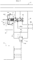
- reference 1 indicates - in its entirety - a braking system for a motor-vehicle, including four hydraulically-operated brake devices F1, F2, F3, F4, associated, respectively, with the four wheels of the vehicle.
- the brake devices F1 and F4 are associated with the two front wheels of the motor-vehicle, while the brake devices F2, F3 are associated with the two rear wheels of the motor-vehicle.
- the configuration of Figure 1 is completely independent of the type of hydraulic brake device associated with each wheel of the vehicle.
- the invention is - in fact - applicable using hydraulically-operated brake devices of any known type (for example, disc brakes or drum brakes).
- the braking system 1 comprises sub-groups 1A, 1B, 1C, 1D, 1E, 1F and an electronic controller E.
- the sub-group 1A is configured to allow a control of the contrasting force of the brake pedal actuation (feedback in force), which causes the feeling on the brake pedal, i.e., the reaction that the driver feels when he actuates the brake pedal.
- the sub-group 1B mainly comprises a master cylinder MC of any known type, intended to generate a fluid pressure following an intervention on the brake pedal.
- the sub-group 1C comprises one or more solenoid valves (in the illustrated example two solenoid valves EV1, EV2) configured to enable or disable the influence of the cylinder MC on one or more brake devices.
- solenoid valves in the illustrated example two solenoid valves EV1, EV2
- the sub-group 1D comprises one or more electrically-operated fluid pressure sources EHAS ("Electro-Hydraulic Actuation System”) designed to create fluid pressure, which adds or replaces the fluid pressure generated by the master cylinder MC to give rise to a hydraulic pressure to actuate the respective brake devices.
- EHAS Electrically-operated fluid pressure sources
- the sub-group 1E comprises a plurality of mechanical pressure transfer devices, each of which has two inlets connected, respectively, to a delivery line of the master cylinder MC and to a respective electrically-operated pressure source EHAS, to supply, accordingly, at its outlet - an actuating pressure of the respective brake device.
- the sub-group 1F consists of the group of brake devices associated with the wheels of the vehicle, which transform the hydraulic pressure supplied thereto into braking torques on the respective wheels.
- the pressure transfer devices are indicated, respectively, with PT1, PT2, PT3, PT4 in the example illustrated in Figure 1 .
- the reference S indicates a discharge and supply reservoir for the hydraulic system.
- the master cylinder MC is of the known type with two pumping pistons arranged operatively in series with each other within a casing 3 and displaceable against the action of springs 4A, 4B due to an intervention on the brake pedal P ( Figure 1 ).
- the brake pedal P is operatively connected to a rod 5, which is - in turn -operatively connected to the piston 2A.
- the inner cavity of the casing 3 communicates with the reservoir S through two inlets 3A, 3B, and also communicates with two delivery lines MC1, MC2 of the master cylinder MC through two outlets 3C, 3D.
- An intervention on the brake pedal P causes a movement of the rod 5 and, consequently, of the first piston 2A of the master cylinder MC, which is operationally connected (in the way that will be described below) to the rod 5.
- the movement of the piston 2A closes the opening 3A and pressurizes the fluid in the chamber of the master cylinder MC communicating with the delivery line MC2.
- the pressure in the chamber comprised between the two pistons 2A, 2B also determines a movement of the second piston 2B, which pressurizes the fluid in the chamber communicating with the delivery line MC1, once the piston 2B has closed the second inlet 3B.
- the predisposition of the inlet openings 3A, 3B allows the possibility of bleeding the air from the braking system, replenishing the volume of air-oil emulsion eliminated during the purging step of the hydraulic circuit with oil from the reservoir S. Furthermore, the inlet openings 3A, 3B communicating with the discharge reservoir S allow recovering the unwanted clearances that are created with the aging of the system, due to the progressive wear of the friction elements used in the brake devices (whether they are disc brakes or drum brakes).
- the sub-group 1A of the system comprises a hydraulic adjustment device of the feeling on the brake pedal, indicated with the reference PFP ("Pedal Feeling Pump").
- the PFP adjustment device comprises a hydraulic cylinder 6, with a pressure chamber 7 having an inlet 8 communicating with a discharge reservoir S, and an outlet 9 communicating with the discharge reservoir S through a line 10 in which a pressure-limiting proportional solenoid valve 11 is interposed, whose solenoid 11A is controlled by the electronic controller E, so as to regulate the passage section through the valve 11 in proportion to the electrical command sent thereto by the electronic controller E.
- a pumping member 12 is slidably mounted inside the hydraulic cylinder 6, having a central body connected on one side, by means of the rod 5, to the brake pedal, and on the other side, by means of a connecting member 13, to the first piston 2A of the master cylinder MC.
- the pumping member 12 may be pushed by the brake pedal, against the action of a spring 14, so as to pressurize the fluid in the chamber 7, since said chamber cannot freely discharge into the discharge reservoir S through the line 10, due to the resistance opposed by the passage through the proportional solenoid valve 11. Therefore, when the brake pedal is operated, it encounters a force opposing its movement, which is, for its predominant part, a function of the pressure existing in the chamber 7.
- the configuration of the PFP device is substantially similar to that adopted for the vacuum-assisted devices used in traditional braking devices.
- the chamber 7 is placed in communication with a vacuum source (for example, the intake manifold of the internal combustion engine of the vehicle) so as to generate an assistance action that helps the movement of the brake pedal.
- a vacuum source for example, the intake manifold of the internal combustion engine of the vehicle
- the chamber 7 is a chamber, which is placed at a controlled pressure, to instead generate a contrast force when the brake pedal is operated. This contrast force causes the feeling that the driver feels when operating the brake pedal.
- the electronic controller E may control the proportional solenoid valve 11, according to any predetermined program, to achieve a required load feedback on the brake pedal, regardless of the operating state of the braking system and regardless of the actuating pressure of the brake devices associated with the vehicle wheels.
- the system comprises one or more sensors 15 (schematically illustrated in Figures 1 , 2 ), which detect one or more parameters indicative of the way in which the brake pedal is actuated, such as the position, speed and acceleration of the brake pedal.
- the electronic controller E adjusts the electric current supplying the solenoid 11A of the proportional solenoid valve 11, so as to achieve the required pressure in the chamber 7 of the PFP device for regulating the feeling on the brake pedal.
- the outlet 9 of the PFP device for adjusting the feeling on the brake pedal communicates with the discharge reservoir S, also by means of a non-return valve 16, arranged in parallel with respect to the proportional solenoid valve 11, which allows a flow of fluid from the reservoir S towards the pressure chamber 7 of the PFP device, in such a way as to favor the filling of the pressure chamber 7 of the PFP device in the return phase of the movable member 12 (and of the brake pedal) towards the rest position.
- the main object of the non-return valve 16 is to:
- the PFP device is integrated into the cylinder MC and has its casing 6 rigidly connected to the casing 3 of the master cylinder MC.
- the PFP device constitutes a separate unit with respect to the master cylinder MC.
- the movable member 12 of the PFP device is, in any case, operatively connected both on one side to the brake pedal and on the other side, by means of a transmission of any type, to the piston 2A of the master cylinder MC.
- the fluid pressure transfer device The fluid pressure transfer device
- the sub-group 1E comprises, in the embodiment illustrated in Figure 1 , four fluid pressure transfer devices PT1, PT2, PT3, PT4, associated with the brake devices F1, F2, F3, F4 of the motor vehicle wheels, respectively.
- the fluid pressure transfer device comprises a cylinder 18 defined by a casing having a cylindrical wall 19 and two end walls 20, 21.
- a movable piston member 23 is slidably mounted within the cavity of the cylindrical wall 19, with the interposition of a sealing ring 22.
- Two inlet openings 24, 25 are formed in the end wall 20 of the cylinder 18 ( Figure 5 ).
- An outlet opening 26 is formed in the end wall 21 of the cylinder 18.
- the movable piston member 23 faces a first upstream chamber 27, central, communicating with the first inlet opening 24, and a second upstream chamber 28, annular, coaxial with the first upstream chamber 27 and communicating with the second inlet opening 25.
- the two upstream chambers 27, 28 are defined by the fact that an axial tubular appendage 29 extends from the face of the movable piston member 23, facing these chambers, which is slidably mounted, with the interposition of a sealing ring 30, around an axial tubular appendage 31 protruding from the end wall 20.
- a variant would also be possible in which the tubular appendage 29 of the movable piston member 23 is arranged to slide inside the tubular appendage 31 of the end wall 20.
- the movable piston member 23 On the side facing the outlet opening 26, the movable piston member 23 has a central portion 23a of reduced diameter, which is slidably mounted, with the interposition of a sealing ring 32 within a tubular appendage 33 axially protruding from the end wall 21.
- a tubular appendage is provided, slidably mounted around the tubular appendage 33.
- a downstream chamber 34 is defined, which communicates with the outlet opening 26.
- the space between the movable piston member 23 and the end wall 21 surrounding the tubular appendage 33 is, instead, placed in communication with the atmosphere through a circumferential series of openings 35 (see also Figure 6 ). Within this space there is a helical spring 36, which tends to oppose a movement of the movable piston member 23 in the direction of the outlet opening 26.
- an EHAS Electronic-Hydraulic Actuation System
- PT1, PT2, PT3, PT4 can be, for example, constituted by an electrically-operated pump of any known type, possibly equipped with a pressurized fluid reservoir.
- Each EHAS has an inlet 37 communicating with the discharge and supply reservoir S, and an outlet 38 connected to the second inlet 25 of the respective pressure transfer device.
- Each electrically-operated fluid pressure source EHAS is controlled by the electronic controller E to provide, when activated, a fluid pressure within the second upstream chamber 28.
- Each electrically-operated fluid pressure source EHAS allows the fluid to flow freely both from the discharge and supply reservoir to the second upstream chamber 28 of the respective pressure transfer device and in a reverse flow direction, ensuring:
- each pressure transfer device communicates with a respective delivery line MC1 or MC2 of the master cylinder MC through one of the aforesaid solenoid valves EV1, EV2 for enabling or disabling the master cylinder MC.
- Each of the solenoid valves EV1, EV2 (the solenoid valve EV1 in Figure 4 ) has a first operating condition (the condition de-energized by the solenoid valve in the example illustrated) in which the solenoid valve creates a free communication passage of a delivery line of the master cylinder MC (the delivery line MC1 in Figure 4 ) with the first inlet 24 of one or more pressure transfer devices PT1, PT2, PT3, PT4.
- each delivery line MC1, MC2 of the master cylinder MC is connected to a respective solenoid valve, respectively, EV1 and EV2, and each of the two solenoid valves EV1, EV2 is connected to two pressure transfer devices, respectively, PT1, PT2 and PT3, PT4, each of which is associated with an electrically-operated fluid pressure source EHAS, and one of the brake devices F1, F2, F3, F4 of a respective wheel of the vehicle.
- the delivery line MC1 of the master cylinder MC communicates with the inlet 24 and with the first upstream chamber 27 of the pressure transfer device PT1.
- an intervention on the brake pedal causes, through the master cylinder MC, the supply of pressurized fluid into the delivery line MC1.
- the fluid pressure reaches the first upstream chamber 27 of the pressure transfer device PT1, which causes a movement of the movable piston member 23, against the action of the spring 36.
- the movement of the piston member 23 creates a transfer of pressurized fluid from the downstream chamber 34, through the outlet 26, to the hydraulic line AL for actuating one of the brake devices F1, F2, F3, F4.
- each pressure transfer device PT1-PT4 In addition to, or instead of the pressure transmitted by the master cylinder MC to the first upstream chamber 27 of each pressure transfer device PT1-PT4, it is possible to supply pressurized fluid to the second upstream chamber 28 of each pressure transfer device PT1-PT4, by activating the respective electrically-operated fluid pressure source EHAS.
- each solenoid valve EV1 when each solenoid valve EV1 is in its de-energized rest condition, in which it allows free communication between the delivery line of the master cylinder MC and the first inlet 24 of each pressure transfer device PT1-PT4, the movement of the movable piston member 23, and consequently the actuation of each brake device, may be determined either solely by the fluid pressure generated by the master cylinder, or also by the fluid pressure generated by the electrically-operated source EHAS, which in this case performs an assist function to the brake.
- the feeling on the brake pedal is controlled in a completely independent way by the electronic controller E, according to any predetermined program, by means of control of the proportional solenoid valve 11.
- the master cylinder may be excluded by moving each solenoid valve EV1 and EV2 into its second operating condition (which, in the example illustrated, is obtained by energizing the solenoid of the solenoid valve EV1, EV2).
- the connection between the delivery line MC1 or MC2 of the master cylinder MC and the first inlet 24 of each pressure transfer device PT1-PT4 is interrupted.
- each pressure transfer device PT1-PT4 is placed in communication with the discharge and supply reservoir supply S, while the delivery line MC1, MC2 of the master cylinder is placed in communication with the discharge and supply reservoir S through a restricted passage 39 ( Figure 4 ), which can be integrated into the solenoid valve EV1 or EV2 or be arranged in the line 40 that connects the corresponding outlet of the solenoid valve with the discharge reservoir.
- each solenoid valve EV1 and EV2 when each solenoid valve EV1 and EV2 is in its second operating condition, any influence of the master cylinder MC on the brake devices is canceled, and the actuation of the brake devices F1, F2, F3, F4 is solely determined by the respective electrically-operated fluid pressure sources EHAS.
- This operating mode may be controlled by the electronic controller E according to any predetermined logic. It can also be activated to obtain an ABS effect when, during braking controlled by the brake pedal, the tendency of one or more wheels of the vehicle to lock is detected, due to the reaching of the grip limit.
- the electronic controller E may detect a condition of incipient locking of a wheel following the receipt of a signal coming from one or more sensors arranged and configured to indicate this condition (for example, a sensor of the angular speed of each wheel, configured to detect a decrease in the angular velocity below a predetermined threshold). Upon the occurrence of this condition, the electronic controller E switches each solenoid valve EV1, EV2 to the operating condition of disabling the master cylinder MC, so that the first upstream chamber 27 of each pressure transfer device PT1-PT4 is discharged, while the movable piston member 23 of each pressure transfer device PT1-PT4 is controlled by the effect of the fluid pressure generated by the respective electrically-operated fluid pressure source EHAS.
- a condition of incipient locking of a wheel following the receipt of a signal coming from one or more sensors arranged and configured to indicate this condition (for example, a sensor of the angular speed of each wheel, configured to detect a decrease in the angular velocity below a predetermined threshold).
- each EHAS device is controlled in such a way as to generate a reduced fluid pressure in the actuation line AL of the brake devices F1-F4, this reduced pressure being chosen in such a way as to avoid locking of the wheel.
- the main functions of the restricted passage 39 associated with each solenoid valve EV1, EV2, are the following:
- each EHAS device allows the free passage of the fluid both from the discharge and supply reservoir towards the second upstream chamber 28 of the pressure transfer device PTi and in a reverse flow direction, guaranteeing:
- each solenoid valve for enabling/disabling the master cylinder EV1, EV2 has a third operating condition, intermediate between its first operating condition and its second operating condition, in which the solenoid valve is temporarily left open in the passage from the first operative condition to the second operative condition, and in the passage from the second operative condition to the first operative condition, so as to avoid a return pressure stroke on the brake pedal.
- the electronic controller E is configured and programmed to control the enabling/disabling solenoid valves EV1, EV2 and the electrically-operated fluid pressure sources EHAS associated with the respective pressure transfer devices PT1-PT4 and to the respective brake devices F1-F4 so as to create one or more of the operating modes described above.
- the electronic controller E may also command different operating modes of the two solenoid valves EV1, EV2 and/or of the different electrically-operated fluid pressure sources EHAS so as to command the brake devices associated with the different wheels of the vehicle in a different way, for example, to achieve a stabilizing effect by means of the Electronic Stability Control (ESC) system.
- ESC Electronic Stability Control
- FIG. 7 shows a second embodiment in which the system described above is used to control only two hydraulically-operated brake devices F1, F4 (for example, associated with the two front wheels or the two rear wheels) while the other two brake devices brake F2, F3 are electrically-operated and are controlled directly by the electronic controller E.
- each of the two delivery lines MC1, MC2 of the master cylinder MC is connected through a respective solenoid valve EV1, EV2, to a single pressure transfer device PT1 or PT2. Therefore, only two pressure transfer devices PT1, PT2 are provided, each connected to a respective electrically-operated fluid pressure source EHAS, for actuating the brake devices F1, F4, which are hydraulically-operated.
- the feeling on the brake pedal is controlled by the electronic controller E, through the adjustment device of the feeling on the pedal PFP and the associated proportional solenoid valve 11, completely independent of the actuation pressure of the brake devices.
- An important characteristic of the invention is the possibility of being used with any type of brake device, in particular, with any type of hydraulically-operated disc brake, with floating or fixed calipers, combined respectively with fixed or floating brake discs.
- the brake discs can also be of any known type, in particular also of the self-ventilating type.
- the system can also be adopted with hydraulically-operated drum brake devices.
- the system according to the invention allows the production costs of the braking system to be significantly reduced, since it can use brake devices of any known type, while being able to introduce new functions.
- the system of the invention also allows the use of safety components designed with technologies and manufactured with processes with a high level of maturity. Therefore, the possible incidence of reliability and safety problems is minimized.
- system of the invention has a wide field of application, since it allows application to any type of vehicle and to any type of wheel suspension.
Abstract
A vehicle braking system comprises a master cylinder (MC) for generating a fluid pressure that causes the actuation of brake devices (F1, F2, F3, F4) associated with the wheels of a vehicle following an intervention on a brake pedal (P). In the delivery line (MC1, MC2) of the master cylinder (MC) there is a pressure transfer device (PT1, PT2, PT3, PT4), which generates a pressure in the hydraulic actuating line (AL) of a respective brake device (F1, F2, F3, F4) following a fluid pressure communicated to a first inlet (24) of the pressure transfer device from the delivery line (MC1, MC2) of the master cylinder (MC) and/or following a fluid pressure supplied to a second inlet (25) of the pressure transfer device from an electrically-operated fluid pressure source (EHAS). A solenoid valve (EV1, EV2) for enabling/disabling the master cylinder (MC) is interposed in the delivery line (MC1, MC2) of the master cylinder (MC). An electronic controller (E) controls the enabling/disabling solenoid valve (EV1, EV2), and the electrically-operated fluid pressure source (EHAS) to create different operating modes of the system. The system does not include any vacuum-operated servo-assisting devices. The master cylinder (MC) is associated with a hydraulic device for adjusting the feeling on the brake pedal (PFP), in which a fluid pressure is generated that opposes the brake pedal (P) actuation. The electronic controller (E) controls the pressure in the device for adjustment of the feeling on the pedal (PFP) by means of a proportional solenoid valve (11) that regulates the communication of the pressure chamber (7) of the device for adjudtment of the feeling on the pedal (PFP) with the discharge and supply reservoir (S).
Description
- The present invention relates to braking systems for vehicles, of the type comprising a master cylinder including at least one pumping piston operatively connected to a brake pedal, and configured to supply pressurized fluid to a delivery line of the master cylinder, following an actuation of the brake pedal, so as to cause the activation of a hydraulically-operated brake device associated with a respective wheel of the vehicle.
- According to one of the conventional techniques in the field of servo-assisted braking systems, a vacuum-operated assisting device is associated with the master cylinder, the assisting device being connected to a vacuum source, for example the intake manifold of the internal combustion engine of the motor-vehicle.
- A first object of the present invention is to provide a braking system that does not require a vacuum-operated assisting device and that is therefore suitable for installation on electrically-powered or hybrid vehicles, as well as on conventional vehicles with internal combustion engines.
- An additional object of the invention is to control the "feeling" on the brake pedal, i.e., the force that opposes the actuation of the brake pedal, in a manner completely independent from the pressure in the hydraulic line for actuating the brake device.
- An additional object of the invention is to provide a braking system that is capable of operating either in a basic operating mode in which the brake device is operated only by the fluid pressure generated by the master cylinder, or in an assisted-braking operating manner, in which the brake device is actuated not only by the fluid pressure generated by the master cylinder, but also by fluid pressure generated by an electrically-operated pressure source, or in an operating mode in which the brake device is operated only by the fluid pressure generated by said electrically-operated pressure source, according to a Brake-by-Wire (BBW) mode.
- An additional object of the invention is to provide a braking system of the type indicated above in which, if necessary, the system is also capable of implementing an ABS operating mode.
- Yet another object of the invention is to achieve all the aforesaid objects with a relatively simple and inexpensive system, which can be used with any type of brake devices, for example disc brakes or drum brakes, and which is applicable to any type of vehicles.
- In order to achieve one or more of the aforesaid objects, the invention is directed to a vehicle braking system having the characteristics indicated at the beginning of the present description, and further characterized in that said system does not include any vacuum-operated assisting device, and in that a hydraulic device for adjustment of the pedal feeling is operatively associated with the brake pedal and is configured to generate and modulate a force that opposes the actuation of the brake pedal, said device for adjustment of the pedal feeling comprising:
- a hydraulic cylinder, with a pressure chamber having an inlet communicating with a discharge reservoir and an outlet communicating with the discharge reservoir through a pressure-limiting proportional solenoid valve, and
- a pumping member movable in the hydraulic cylinder and operatively connected to the brake pedal, in such a way as to pressurize the fluid in the pressure chamber following an actuation of the brake pedal, so as to generate said force that opposes the actuation of the brake pedal,
- In a first solution, the aforesaid hydraulic device for adjustment of the pedal feeling is integrated into the master cylinder and has a casing rigidly connected to the master cylinder casing, with the aforesaid movable member of the device for adjustment of the pedal feeling being rigidly connected to said at least one pumping piston of the master cylinder.
- In a variant, the hydraulic device for adjustment of the pedal feeling is a unit separate from said master cylinder and has its movable member that is operatively connected - by means of a transmission - to said at least one pumping piston of the master cylinder.
- Thanks to the aforesaid characteristics, the feeling on the brake pedal can be modified in real time by simply configuring the software parameters, completely independently of the operating status of the braking system.
- According to another characteristic, the hydraulic device for adjustment of the pedal feeling has its outlet connected to the discharge reservoir also by means of a one-way valve, arranged in parallel to the aforesaid proportional solenoid valve, to enable a flow from the reservoir towards the pressure chamber of the device, in such a way as to facilitate the filling of the pressure chamber of the device in the return phase of the movable member and of the brake pedal towards their rest positions.
- Thanks to the provision of this non-return valve, a regular return movement of the brake pedal towards its rest position after braking is possible, allowing the return of fluid into the pressure chamber of the hydraulic cylinder through this valve even before this pressure chamber returns to communicate directly with the reservoir through the inlet opening of the hydraulic cylinder, following the return movement of the movable member within the cylinder. In this way, cavitation phenomena are also avoided inside the device for adjustment of the pedal feeling, which - in the face of repeated operations - could damage this device.
- Another relevant characteristic of the braking system according to the invention lies in that the brake device can be operated both by the fluid pressure generated by the master cylinder and, in addition or alternatively thereto, by a fluid pressure generated from an electrically-operated fluid pressure source, in a Brake-by-Wire (BBW) mode.
- To obtain this result, according to another characteristic of the braking system of the invention, the system also comprises a mechanical pressure transfer device, for transferring hydraulic pressure from the delivery line of the master cylinder to a hydraulic line for actuating the brake device. The pressure transfer device comprises a cylinder with a piston member, which is movable within the cylinder between a first upstream chamber, communicating with the delivery line of the master cylinder and a downstream chamber, communicating with the hydraulic actuating line of the brake device. In this way, the pressure generated by the master cylinder in said delivery line, following an intervention on the brake pedal, causes a movement of the piston member of the pressure transfer device, which - in turn - generates a pressure in the hydraulic actuating line of the brake device. Furthermore, the pressure transfer device comprises a second upstream chamber, operatively arranged in parallel with said first upstream chamber and connected to an electrically-operated fluid pressure source.
- In this way, the movement of the piston member of the pressure transfer device, which generates the pressure in the hydraulic actuating line of the brake device, can be caused not only by the pressure in the delivery line of the master cylinder, but also, in addition or alternatively thereto, by the pressure generated by said electrically-operated fluid pressure source.
- According to another characteristic, in the delivery line of the master cylinder, between the outlet of the master cylinder and said upstream first chamber of the pressure transfer device, a solenoid valve for enabling/disabling the master cylinder is interposed, having a first operating condition, in which it causes the outlet of the master cylinder to communicate with said first upstream chamber of the pressure transfer device, and a second operating condition, in which the first upstream chamber of the pressure transfer device is placed in communication with the discharge reservoir, and in which the outlet of the master cylinder is placed in communication with the discharge reservoir through a restricted passage.
- In the preferred embodiment, said solenoid valve for enabling/disabling the master cylinder is in said first enabling operating condition of the master cylinder when it is de-energized, and is in said second disabling operating condition of the master cylinder when it is energized.
- In a variant, the solenoid valve for enabling/disabling the master cylinder has a third operating condition, intermediate between its first operating condition and its second operating condition, in which the solenoid valve is temporarily left open when a passage is commanded from the first operating position to the second operating position or vice versa, in such a way as to avoid a return pressure stroke on the brake pedal.
- Thanks to the aforesaid characteristics, the electronic controller can be configured and programmed to control the solenoid valve for enabling/disabling the master cylinder, and the aforesaid electrically-operated fluid pressure source, so as to be able to selectively activate one or more of the following operating modes:
- a basic braking operating mode, in which said solenoid valve for enabling/disabling the master cylinder is in its first enabling operating condition of the master cylinder, and the electrically-operated fluid pressure source is inactive, so that the brake device is operated by the brake pedal by means of the master cylinder,
- an assisted-braking operating mode, in which said solenoid valve for enabling/disabling the master cylinder is in its first enabling operating condition of the master cylinder, and the electrically-operated fluid pressure source is active, so that the brake device is operated by the brake pedal by means of the master cylinder, but the fluid pressure supplied to the brake device is the result of both the pressure generated by the master cylinder and the pressure generated by the electrically-operated fluid pressure source,
- an electric-only braking operating mode, in which said solenoid valve for enabling/disabling the master cylinder is in its second operating condition disabling the master cylinder, and the electrically-operated fluid pressure source is active, so that the brake device is only operated by the pressure generated by said electrically-operated fluid pressure source, and
- an operating mode for activating an ABS effect, in which, following detection by the electronic controller of a condition of incipient locking of a vehicle wheel during braking (controlled by the brake pedal through the master cylinder) said solenoid valve for enabling/disabling the master cylinder is switched from its first enabling operating condition to its second disabling operating condition of the master cylinder, and said electrically-operated fluid pressure source is activated to generate a reduced pressure in the supply line of the brake device, in order to avoid locking of the wheel during braking.
- In this last condition described above, in which the solenoid valve for enabling/disabling the master cylinder is switched to the disabling condition, the outlet opening of the master cylinder is indirectly connected to the discharge, through the aforesaid restricted passage, so that rapid emptying of the master cylinder chamber is prevented, so as to prevent the brake pedal from moving suddenly to its fully lowered position due to instantaneous cancellation of the pressure in the master cylinder.
- The aforesaid restricted passage may be integrated into the solenoid valve for enabling/disabling the master cylinder, or it can be arranged in the communication line between this solenoid valve and the discharge reservoir.
- When the electrically-operated fluid pressure source is activated, it is controlled by the electronic controller based on signals received from the electronic controller and indicative of one or more pedal operating parameters (such as position, speed and acceleration of the pedal) and/or of one or more operating parameters of the vehicle (such as the angular speed of rotation of the respective vehicle wheel).
- In an actual embodiment, the master cylinder is of the tandem type, comprising at least two pumping pistons operatively arranged in series with each other and configured to supply pressurized fluid to at least two delivery lines of the master cylinder, following actuation of the brake pedal. In each of said at least two delivery lines of the master cylinder a respective solenoid valve is interposed for enabling/disabling the master cylinder, which controls the connection between a respective outlet of the master cylinder and one or more mechanical pressure transfer devices. Each of said mechanical pressure transfer devices is connected to a respective electrically-operated fluid pressure source and is arranged to generate fluid pressure in the hydraulic actuating line of a respective brake device.
- In a first solution, which refers to a motor-vehicle with front wheels and rear wheels all equipped with hydraulically-operated brake devices (for example, disc brakes or drum brakes), each of the two aforesaid delivery lines of the master cylinder controls two brake devices associated with two wheels of the vehicle, by means of a respective enabling/disabling solenoid valve, connected to two mechanical pressure transfer devices that control the fluid pressure in the actuating lines of the two brake devices, and that are also each connected to a respective electrically-operated fluid pressure source.
- In a second solution, which refers to a motor-vehicle having two wheels equipped with hydraulically-operated brake devices and two wheels equipped with electrically-operated brake devices, each of the two delivery lines of the master cylinder controls only one respective brake device associated with a vehicle wheel, by means of an enabling/disabling solenoid valve connected to a pressure transfer device, which controls the fluid pressure in the actuating line of said respective brake device, and which is also connected to a respective electrically-operated fluid pressure source, the aforesaid system also includes two electrically-operated brake devices associated with two additional wheels of the vehicle, which are directly controlled by said electronic controller.
- The invention also relates to a method for controlling a braking system of a vehicle, according to what is indicated in the attached
claim 15. - Thanks to all the characteristics indicated above, the braking system according to the invention provides a number of relevant advantages.
- Firstly, the system does not require vacuum-operated servo-assistance, so that it is applicable on electrically-powered vehicles and hybrid vehicles, as well as on vehicles with conventional internal combustion engines.
- Furthermore, in the system according to the invention, the feeling on the brake pedal can be controlled in any predetermined way, regardless of the actuating pressure of the brake devices.
- As indicated above, the braking system according to the invention is capable of operating both as a conventional system, in which the supply pressure of the brake device is generated by the master cylinder following intervention on the brake pedal, and as an assisted-braking system, in which the actuating pressure of the brake device is generated by the joint contribution of the master cylinder and the electrically-operated pressure source. Finally, the braking system according to the invention may operate by exploiting only the pressure generated by the electrically-operated pressure source, according to a Brake-by-Wire mode that can be activated and controlled by the aforesaid electronic controller according to any predetermined logic, therefore even in self-driving vehicles.
- Switching between the different operating modes is achieved simply by controlling the solenoid valve for enabling/disabling the master cylinder that is associated with each delivery line of the master cylinder, and by controlling the electrically-operated pressure source that is associated with each hydraulically-operated brake device. The pressure transfer device, which is also associated with each hydraulically-operated brake device, has two inlets connected, respectively, to the delivery line of the master cylinder and to the electrically-actuated pressure source, and an outlet connected to the actuating line of the brake device and is thus capable of generating an actuating pressure of the brake device, which is the result of the pressure generated by the master cylinder and/or of the pressure generated by the electrically-operated pressure source.
- As shown above, the system according to the invention is also able to obtain an ABS effect if tendency is detected of a vehicle wheel to lock during a braking controlled by the brake pedal. In this case, the electronic controller, which detects the need for ABS intervention following the signals received from one or more sensors (for example, from a sensor that detects a decrease in the angular speed of the wheel below a predetermined threshold), causes the disabling of the master cylinder and the continuation of braking by means of the intervention of the electrically-operated pressure source only, which is adjusted to achieve a reduced braking pressure, such as to avoid locking of the wheel.
- As already indicated, in all the operating modes described above, the force that opposes the actuation of the brake pedal, i.e. the feeling on the brake pedal, is regulated in any predetermined way by means of the aforesaid device for adjustment of the feeling on the brake pedal, regardless of the operating pressure of the brake device.
- The braking pressure supplied to the brake devices associated with the different wheels of the vehicle can also be controlled in different ways by the electronic controller, for the need to provide an ABS effect only on the wheels that tend to lock, and for obtaining a stabilizing effect if an electronic vehicle stability control system detects the need for a correction control. The electronic controller is also able to manage the blending between the different braking modes, ensuring both braking performance and comfort for the vehicle occupants at the same time.
- Further characteristics and advantages of the invention will become apparent from the description that follows with reference to the attached drawings, provided purely by way of non-limiting example, in which:
-
Figure 1 is a diagram of a first embodiment of the braking system according to the invention, -
Figure 2 illustrates a detail ofFigure 1 on an enlarged scale, -
Figure 3 illustrates an additional detail ofFigure 2 on an enlarged scale, -
Figure 4 illustrates an additional detail ofFigure 1 on an enlarged scale, -
Figure 5 illustrates a detail ofFigure 4 on an enlarged scale, -
Figure 6 is an exploded perspective view of the components shown inFigure 5 , and -
Figure 7 is a diagram of a second embodiment of the system according to the invention, - In
Figure 1 ,reference 1 indicates - in its entirety - a braking system for a motor-vehicle, including four hydraulically-operated brake devices F1, F2, F3, F4, associated, respectively, with the four wheels of the vehicle. In the example, the brake devices F1 and F4 are associated with the two front wheels of the motor-vehicle, while the brake devices F2, F3 are associated with the two rear wheels of the motor-vehicle. Of course, the configuration ofFigure 1 is completely independent of the type of hydraulic brake device associated with each wheel of the vehicle. The invention is - in fact - applicable using hydraulically-operated brake devices of any known type (for example, disc brakes or drum brakes). - Referring again to
Figure 1 , thebraking system 1 comprisessub-groups - The
sub-group 1A is configured to allow a control of the contrasting force of the brake pedal actuation (feedback in force), which causes the feeling on the brake pedal, i.e., the reaction that the driver feels when he actuates the brake pedal. - The
sub-group 1B mainly comprises a master cylinder MC of any known type, intended to generate a fluid pressure following an intervention on the brake pedal. - The
sub-group 1C comprises one or more solenoid valves (in the illustrated example two solenoid valves EV1, EV2) configured to enable or disable the influence of the cylinder MC on one or more brake devices. - The sub-group 1D comprises one or more electrically-operated fluid pressure sources EHAS ("Electro-Hydraulic Actuation System") designed to create fluid pressure, which adds or replaces the fluid pressure generated by the master cylinder MC to give rise to a hydraulic pressure to actuate the respective brake devices.
- The
sub-group 1E comprises a plurality of mechanical pressure transfer devices, each of which has two inlets connected, respectively, to a delivery line of the master cylinder MC and to a respective electrically-operated pressure source EHAS, to supply, accordingly, at its outlet - an actuating pressure of the respective brake device. - The
sub-group 1F consists of the group of brake devices associated with the wheels of the vehicle, which transform the hydraulic pressure supplied thereto into braking torques on the respective wheels. - The pressure transfer devices are indicated, respectively, with PT1, PT2, PT3, PT4 in the example illustrated in
Figure 1 . - Again, with reference to
Figure 1 , the reference S indicates a discharge and supply reservoir for the hydraulic system. - The configuration and operation of the
different sub-groups - In the example of
Figures 1 and3 , the master cylinder MC is of the known type with two pumping pistons arranged operatively in series with each other within acasing 3 and displaceable against the action ofsprings Figure 1 ). The brake pedal P is operatively connected to arod 5, which is - in turn -operatively connected to thepiston 2A. The inner cavity of thecasing 3 communicates with the reservoir S through twoinlets outlets - An intervention on the brake pedal P (
Figure 1 ) causes a movement of therod 5 and, consequently, of thefirst piston 2A of the master cylinder MC, which is operationally connected (in the way that will be described below) to therod 5. The movement of thepiston 2A closes theopening 3A and pressurizes the fluid in the chamber of the master cylinder MC communicating with the delivery line MC2. At the same time, the pressure in the chamber comprised between the twopistons second piston 2B, which pressurizes the fluid in the chamber communicating with the delivery line MC1, once thepiston 2B has closed thesecond inlet 3B. - The predisposition of the
inlet openings inlet openings - With reference again to
Figures 2 ,3 , thesub-group 1A of the system according to the invention comprises a hydraulic adjustment device of the feeling on the brake pedal, indicated with the reference PFP ("Pedal Feeling Pump"). The PFP adjustment device comprises ahydraulic cylinder 6, with apressure chamber 7 having aninlet 8 communicating with a discharge reservoir S, and anoutlet 9 communicating with the discharge reservoir S through aline 10 in which a pressure-limitingproportional solenoid valve 11 is interposed, whosesolenoid 11A is controlled by the electronic controller E, so as to regulate the passage section through thevalve 11 in proportion to the electrical command sent thereto by the electronic controller E.A pumping member 12 is slidably mounted inside thehydraulic cylinder 6, having a central body connected on one side, by means of therod 5, to the brake pedal, and on the other side, by means of a connectingmember 13, to thefirst piston 2A of the master cylinder MC. - The pumping
member 12 may be pushed by the brake pedal, against the action of aspring 14, so as to pressurize the fluid in thechamber 7, since said chamber cannot freely discharge into the discharge reservoir S through theline 10, due to the resistance opposed by the passage through theproportional solenoid valve 11. Therefore, when the brake pedal is operated, it encounters a force opposing its movement, which is, for its predominant part, a function of the pressure existing in thechamber 7. - It may be observed that the configuration of the PFP device is substantially similar to that adopted for the vacuum-assisted devices used in traditional braking devices. In these conventional devices, the
chamber 7 is placed in communication with a vacuum source (for example, the intake manifold of the internal combustion engine of the vehicle) so as to generate an assistance action that helps the movement of the brake pedal. Conversely, in the braking system according to the invention there is no vacuum servo-assistance device and thechamber 7 is a chamber, which is placed at a controlled pressure, to instead generate a contrast force when the brake pedal is operated. This contrast force causes the feeling that the driver feels when operating the brake pedal. - The electronic controller E may control the
proportional solenoid valve 11, according to any predetermined program, to achieve a required load feedback on the brake pedal, regardless of the operating state of the braking system and regardless of the actuating pressure of the brake devices associated with the vehicle wheels. - To this end, the system according to the invention comprises one or more sensors 15 (schematically illustrated in
Figures 1 ,2 ), which detect one or more parameters indicative of the way in which the brake pedal is actuated, such as the position, speed and acceleration of the brake pedal. On the basis of the signals sent by the sensor orsensors 15, the electronic controller E adjusts the electric current supplying thesolenoid 11A of theproportional solenoid valve 11, so as to achieve the required pressure in thechamber 7 of the PFP device for regulating the feeling on the brake pedal. - Again with reference to
Figures 1 ,2 , theoutlet 9 of the PFP device for adjusting the feeling on the brake pedal communicates with the discharge reservoir S, also by means of anon-return valve 16, arranged in parallel with respect to theproportional solenoid valve 11, which allows a flow of fluid from the reservoir S towards thepressure chamber 7 of the PFP device, in such a way as to favor the filling of thepressure chamber 7 of the PFP device in the return phase of the movable member 12 (and of the brake pedal) towards the rest position. The main object of thenon-return valve 16 is to: - allowing the brake pedal to return to its rest position, without jamming, at the end of braking, allowing the
chamber 7 of the PFP device to be filled during the return movement of themovable member 12 even before the movable member opens the openinginlet 8, e - avoid cavitation phenomena inside the PFP device which, following repeated operations, could damage the PFP device.
- In the example illustrated in the attached drawings, the PFP device is integrated into the cylinder MC and has its
casing 6 rigidly connected to thecasing 3 of the master cylinder MC. However, it can also be envisaged that the PFP device constitutes a separate unit with respect to the master cylinder MC. In this case, themovable member 12 of the PFP device is, in any case, operatively connected both on one side to the brake pedal and on the other side, by means of a transmission of any type, to thepiston 2A of the master cylinder MC. - The
sub-group 1E comprises, in the embodiment illustrated inFigure 1 , four fluid pressure transfer devices PT1, PT2, PT3, PT4, associated with the brake devices F1, F2, F3, F4 of the motor vehicle wheels, respectively. With reference in particular toFigures 4 ,5 and 6 , which illustrate the circuit associated with the device PT1 (the remaining devices are completely identical), the fluid pressure transfer device comprises acylinder 18 defined by a casing having acylindrical wall 19 and twoend walls movable piston member 23 is slidably mounted within the cavity of thecylindrical wall 19, with the interposition of a sealingring 22. - Two
inlet openings end wall 20 of the cylinder 18 (Figure 5 ). Anoutlet opening 26 is formed in theend wall 21 of thecylinder 18. - On the side facing the
inlet openings movable piston member 23 faces a firstupstream chamber 27, central, communicating with the first inlet opening 24, and a secondupstream chamber 28, annular, coaxial with the firstupstream chamber 27 and communicating with the second inlet opening 25. - In the specific embodiment illustrated, the two
upstream chambers tubular appendage 29 extends from the face of themovable piston member 23, facing these chambers, which is slidably mounted, with the interposition of a sealingring 30, around an axialtubular appendage 31 protruding from theend wall 20. A variant would also be possible in which thetubular appendage 29 of themovable piston member 23 is arranged to slide inside thetubular appendage 31 of theend wall 20. In any case, whatever the position assumed by themovable piston member 23 within thecylinder 18, the aforesaidtubular appendages upstream chamber 27 remains isolated from the secondupstream chamber 28. - On the side facing the
outlet opening 26, themovable piston member 23 has a central portion 23a of reduced diameter, which is slidably mounted, with the interposition of a sealingring 32 within atubular appendage 33 axially protruding from theend wall 21. A variant would be possible in which, instead of the portion of reduced diameter 23a, a tubular appendage is provided, slidably mounted around thetubular appendage 33. - As a result of the arrangement described above, between the central portion 23a of the
movable piston member 23 and the end wall 21 adownstream chamber 34 is defined, which communicates with theoutlet opening 26. The space between themovable piston member 23 and theend wall 21 surrounding thetubular appendage 33 is, instead, placed in communication with the atmosphere through a circumferential series of openings 35 (see alsoFigure 6 ). Within this space there is ahelical spring 36, which tends to oppose a movement of themovable piston member 23 in the direction of theoutlet opening 26. - With reference now to
Figures 1 and4 , an EHAS ("Electro-Hydraulic Actuation System") fluid pressure source is associated with each of the pressure transfer devices PT1, PT2, PT3, PT4, which can be, for example, constituted by an electrically-operated pump of any known type, possibly equipped with a pressurized fluid reservoir. Each EHAS has aninlet 37 communicating with the discharge and supply reservoir S, and anoutlet 38 connected to thesecond inlet 25 of the respective pressure transfer device. Each electrically-operated fluid pressure source EHAS is controlled by the electronic controller E to provide, when activated, a fluid pressure within the secondupstream chamber 28. - Each electrically-operated fluid pressure source EHAS allows the fluid to flow freely both from the discharge and supply reservoir to the second
upstream chamber 28 of the respective pressure transfer device and in a reverse flow direction, ensuring: - minimization of the resistance to advancement of the
movable piston member 23, and the absence of cavitation phenomena during the actuating step of the brake pedal, when themovable piston member 23 is operated by the pressurized fluid supplied to thefirst inlet 24, and - minimization of the resistance to return of the
movable piston member 23 and the absence of jamming phenomena, when themember 23 is returned to its rest position by thespring 36, during the brake pedal release phase. - Again with reference to
Figure 1 , thefirst inlet 24 of each pressure transfer device communicates with a respective delivery line MC1 or MC2 of the master cylinder MC through one of the aforesaid solenoid valves EV1, EV2 for enabling or disabling the master cylinder MC. Each of the solenoid valves EV1, EV2 (the solenoid valve EV1 inFigure 4 ) has a first operating condition (the condition de-energized by the solenoid valve in the example illustrated) in which the solenoid valve creates a free communication passage of a delivery line of the master cylinder MC (the delivery line MC1 inFigure 4 ) with thefirst inlet 24 of one or more pressure transfer devices PT1, PT2, PT3, PT4. As already indicated, in the embodiment ofFigure 1 , each delivery line MC1, MC2 of the master cylinder MC is connected to a respective solenoid valve, respectively, EV1 and EV2, and each of the two solenoid valves EV1, EV2 is connected to two pressure transfer devices, respectively, PT1, PT2 and PT3, PT4, each of which is associated with an electrically-operated fluid pressure source EHAS, and one of the brake devices F1, F2, F3, F4 of a respective wheel of the vehicle. - With reference again to
Figure 4 , when the solenoid valve EV1 is in its de-energized rest condition, the delivery line MC1 of the master cylinder MC communicates with theinlet 24 and with the firstupstream chamber 27 of the pressure transfer device PT1. In this condition, an intervention on the brake pedal causes, through the master cylinder MC, the supply of pressurized fluid into the delivery line MC1. The fluid pressure reaches the firstupstream chamber 27 of the pressure transfer device PT1, which causes a movement of themovable piston member 23, against the action of thespring 36. The movement of thepiston member 23 creates a transfer of pressurized fluid from thedownstream chamber 34, through theoutlet 26, to the hydraulic line AL for actuating one of the brake devices F1, F2, F3, F4. - In addition to, or instead of the pressure transmitted by the master cylinder MC to the first
upstream chamber 27 of each pressure transfer device PT1-PT4, it is possible to supply pressurized fluid to the secondupstream chamber 28 of each pressure transfer device PT1-PT4, by activating the respective electrically-operated fluid pressure source EHAS. - As a result of the arrangement described above, when each solenoid valve EV1 is in its de-energized rest condition, in which it allows free communication between the delivery line of the master cylinder MC and the
first inlet 24 of each pressure transfer device PT1-PT4, the movement of themovable piston member 23, and consequently the actuation of each brake device, may be determined either solely by the fluid pressure generated by the master cylinder, or also by the fluid pressure generated by the electrically-operated source EHAS, which in this case performs an assist function to the brake. - Of course, whatever the operation mode selected, the feeling on the brake pedal is controlled in a completely independent way by the electronic controller E, according to any predetermined program, by means of control of the
proportional solenoid valve 11. - If the action of the electrically-operated fluid pressure source EHAS has to completely replace the action of the master cylinder, the master cylinder may be excluded by moving each solenoid valve EV1 and EV2 into its second operating condition (which, in the example illustrated, is obtained by energizing the solenoid of the solenoid valve EV1, EV2). In this second operating condition, the connection between the delivery line MC1 or MC2 of the master cylinder MC and the
first inlet 24 of each pressure transfer device PT1-PT4 is interrupted. At the same time, thefirst inlet 24 of each pressure transfer device PT1-PT4 is placed in communication with the discharge and supply reservoir supply S, while the delivery line MC1, MC2 of the master cylinder is placed in communication with the discharge and supply reservoir S through a restricted passage 39 (Figure 4 ), which can be integrated into the solenoid valve EV1 or EV2 or be arranged in theline 40 that connects the corresponding outlet of the solenoid valve with the discharge reservoir. - Therefore, when each solenoid valve EV1 and EV2 is in its second operating condition, any influence of the master cylinder MC on the brake devices is canceled, and the actuation of the brake devices F1, F2, F3, F4 is solely determined by the respective electrically-operated fluid pressure sources EHAS. This operating mode may be controlled by the electronic controller E according to any predetermined logic. It can also be activated to obtain an ABS effect when, during braking controlled by the brake pedal, the tendency of one or more wheels of the vehicle to lock is detected, due to the reaching of the grip limit. According to a technique known per se, the electronic controller E may detect a condition of incipient locking of a wheel following the receipt of a signal coming from one or more sensors arranged and configured to indicate this condition (for example, a sensor of the angular speed of each wheel, configured to detect a decrease in the angular velocity below a predetermined threshold). Upon the occurrence of this condition, the electronic controller E switches each solenoid valve EV1, EV2 to the operating condition of disabling the master cylinder MC, so that the first
upstream chamber 27 of each pressure transfer device PT1-PT4 is discharged, while themovable piston member 23 of each pressure transfer device PT1-PT4 is controlled by the effect of the fluid pressure generated by the respective electrically-operated fluid pressure source EHAS. Consequently, the respective brake devices F1-F4 are actuated by the effect of the pressure generated solely by the EHAS devices. In the condition of incipient locking of one or more wheels, each EHAS device is controlled in such a way as to generate a reduced fluid pressure in the actuation line AL of the brake devices F1-F4, this reduced pressure being chosen in such a way as to avoid locking of the wheel. - The main functions of the restricted
passage 39 associated with each solenoid valve EV1, EV2, are the following: - to ensure that the driver does not experience a block in the positioning of the brake pedal when performing assisted braking or emergency braking; this results in ensuring that the movable member of the master cylinder can continue to move even in the case of a controlled interruption of the hydraulic connection between the master cylinder and the pressure transfer device associated therewith;
- to ensure that the driver continues to experience load feedback resistant to brake pedal advancement even when performing assisted braking or emergency braking; this results in guaranteeing a pressure difference between upstream and downstream of the restricted
passage 39 at a flow rate of the oil coming from the master cylinder; in fact, this specific function would not be achievable by means of a free communication line towards the discharge and supply reservoir. - At the same time, each EHAS device allows the free passage of the fluid both from the discharge and supply reservoir towards the second
upstream chamber 28 of the pressure transfer device PTi and in a reverse flow direction, guaranteeing: - minimization of the resistance to advancement of the
movable piston member 23, and the absence of cavitation phenomena during the actuating step of the brake pedal, when themovable piston member 23 is operated by the pressurized fluid supplied to thefirst inlet 24, and - minimization of the resistance to return of the
movable piston member 23 and the absence of jamming phenomena, when themember 23 is returned to its rest position by thespring 36, during the brake pedal release phase. - In another embodiment, each solenoid valve for enabling/disabling the master cylinder EV1, EV2, has a third operating condition, intermediate between its first operating condition and its second operating condition, in which the solenoid valve is temporarily left open in the passage from the first operative condition to the second operative condition, and in the passage from the second operative condition to the first operative condition, so as to avoid a return pressure stroke on the brake pedal.
- As is evident from the above description, the electronic controller E is configured and programmed to control the enabling/disabling solenoid valves EV1, EV2 and the electrically-operated fluid pressure sources EHAS associated with the respective pressure transfer devices PT1-PT4 and to the respective brake devices F1-F4 so as to create one or more of the operating modes described above. The electronic controller E may also command different operating modes of the two solenoid valves EV1, EV2 and/or of the different electrically-operated fluid pressure sources EHAS so as to command the brake devices associated with the different wheels of the vehicle in a different way, for example, to achieve a stabilizing effect by means of the Electronic Stability Control (ESC) system.
-
Figure 7 shows a second embodiment in which the system described above is used to control only two hydraulically-operated brake devices F1, F4 (for example, associated with the two front wheels or the two rear wheels) while the other two brake devices brake F2, F3 are electrically-operated and are controlled directly by the electronic controller E. In the case of the embodiment ofFigure 7 , each of the two delivery lines MC1, MC2 of the master cylinder MC is connected through a respective solenoid valve EV1, EV2, to a single pressure transfer device PT1 or PT2. Therefore, only two pressure transfer devices PT1, PT2 are provided, each connected to a respective electrically-operated fluid pressure source EHAS, for actuating the brake devices F1, F4, which are hydraulically-operated. - In all the embodiments described above, whatever the chosen embodiment is and whatever the operating mode adopted, the feeling on the brake pedal is controlled by the electronic controller E, through the adjustment device of the feeling on the pedal PFP and the associated
proportional solenoid valve 11, completely independent of the actuation pressure of the brake devices. - An important characteristic of the invention is the possibility of being used with any type of brake device, in particular, with any type of hydraulically-operated disc brake, with floating or fixed calipers, combined respectively with fixed or floating brake discs. The brake discs can also be of any known type, in particular also of the self-ventilating type. Likewise, the system can also be adopted with hydraulically-operated drum brake devices.
- Thanks to all the aforesaid characteristics, the system according to the invention allows the production costs of the braking system to be significantly reduced, since it can use brake devices of any known type, while being able to introduce new functions. The system of the invention also allows the use of safety components designed with technologies and manufactured with processes with a high level of maturity. Therefore, the possible incidence of reliability and safety problems is minimized.
- Furthermore, the system of the invention has a wide field of application, since it allows application to any type of vehicle and to any type of wheel suspension.
- Of course, without prejudice to the principle of the invention, the details of construction and the embodiments may vary widely with respect to those described and illustrated purely by way of example, without departing from the scope of the present invention, as defined by the attached claims.
Claims (18)
- A motor-vehicle braking system, comprising:a master cylinder (MC) including at least one pumping piston (2A, 2B) operatively connected to a brake pedal (P) and configured to supply pressurized fluid to a delivery line (MC1, MC2) of the master cylinder (MC) following an actuation of the brake pedal (P), so as to cause activation of a hydraulically-operated brake device (F1, F2, F3, F4) associated with a respective wheel of the vehicle,said braking system being characterized in that it does not comprise any vacuum-operated assisting device and in that a hydraulic adjustment device of the pedal feeling (PFP) is operatively associated with the brake pedal (P) and configured to generate and modulate a force that opposes the actuation of the brake pedal (P),said adjustment device of the pedal feeling (PFP) comprising:- a hydraulic cylinder (6), with a pressure chamber (7) having an inlet (8) communicating with a discharge and supply reservoir (S) and an outlet (9) communicating with the discharge and supply reservoir (S) by means of a pressure-limiting proportional solenoid valve (11), and- a pumping member (12) movable in the hydraulic cylinder (6) and operatively connected to the brake pedal (P), in such a way as to pressurize the fluid in the pressure chamber (7) following an actuation of the brake pedal (P), so as to generate said force that opposes the actuation of the brake pedal (P),said braking system also comprising an electronic controller (E), configured and programmed to control said proportional pressure-limiting solenoid valve (11) which communicates the outlet of the pressure chamber (9) to the discharge and supply reservoir (S), in such a way as to vary the pressure within said pressure chamber (7) and, therefore, the feeling on the brake pedal (P), based on signals received by said electronic controller (E), and indicative of one or more parameters selected among position of the brake pedal (P), speed of the brake pedal (P) and acceleration of the brake pedal (P).
- A braking system according to claim 1, characterized in that said hydraulic adjustment device of the pedal feeling (PFP) is integrated into the master cylinder (MC) and has a casing (6) rigidly connected to the casing (3) of the master cylinder (MC) with said movable member (12) of the adjustment device of the pedal feeling (PFP), which is rigidly connected to said at least one pumping piston (2A) of the master cylinder (MC).
- A braking system according to claim 1, characterized in that said hydraulic adjustment device of the pedal feeling (PFP) is a unit separate from said master cylinder (MC) and has its movable member (12) which is operatively connected, by means of a transmission, to said at least one piston (2A) of the master cylinder (MC).
- A braking system according to claim 1, characterized in that said hydraulic adjustment device of the pedal feeling (PFP) has its outlet (9), which is connected to the discharge and supply reservoir (S) also by means of a one-way valve (16), arranged in parallel to the aforesaid proportional solenoid valve (11), to enable a flow from the reservoir (S) towards the pressure chamber (7) of the hydraulic adjustment device of the pedal feeling (PFP), in such a way as to facilitate filling of the pressure chamber (7) of said device when the movable member (12) and the brake pedal (P) return towards rest positions.
- A braking system according to claim 1, characterized in that it comprises a pressure transfer device (PT1, PT2, PT3, PT4), for transferring hydraulic pressure from the delivery line (MC1, MC2) of the master cylinder (MC) to a hydraulic actuating line (AL) of the brake device (F1, F2, F3, F4) and in that said pressure transfer device (PT1, PT2, PT3, PT4) comprises:- a cylinder (18), with a member (23) movable within the cylinder (18) between a first upstream chamber (28), communicating with the delivery line (MC1, MC2) of the master cylinder (MC), and a downstream chamber (34), communicating with the hydraulic actuating line (AL) of the brake device (F1, F2, F3, F4), in such a way that the pressure generated by said master cylinder (MC) in said delivery line (MC1, MC2), following an intervention on the brake pedal (P) causes a movement of the movable member (23) of the pressure transfer device (PT1, PT2, PT3, PT4), which generates a resulting pressure in the hydraulic actuating line (AL) of the brake device (F1, F2, F3, F4),said pressure transfer device (PT1, PT2, PT3, PT4) also comprising a second upstream chamber (28) operatively arranged in parallel with said first upstream chamber (27), and
said braking system also comprising an electrically-operated fluid pressure source (EHAS), in such a way that, regardless of the pressure in the delivery line (MC1, MC2) of the master cylinder (MC), the movable member (23) of the pressure transfer device (PT1, PT2, PT3, PT4) can be operated by said electrically-operated fluid pressure source (EHAS), to generate a pressure in the hydraulic actuating line (AL) of the brake device (F1, F2, F3, F4). - A braking system according to claim 5, characterized in that said first upstream chamber (27) and said second upstream chamber (28) of the pressure transfer device (PT1, PT2, PT3, PT4) are arranged coaxially to each other around each other.
- A braking system according to claim 6, characterized in that:- said pressure transfer device (PT1, PT2, PT3, PT4) has a casing (18) defining a cylindrical cavity,- the movable member (23) of the pressure transfer device (PT1, PT2, PT3, PT4) is in the form of a piston slidably mounted within said cylindrical cavity and having a first face facing said upstream chambers (27, 28), and a second face facing said downstream chamber (34),- the body of said piston (23) of the pressure transfer device (PT1, PT2, PT3, PT4) has a tubular appendage (29), protruding axially from said first face, which appendage is slidably mounted around or within a tubular appendage (31) protruding axially from a first end wall (20) of the casing (18),in such a way that the aforesaid first upstream chamber (27) is defined inside said tubular appendages (29, 31), and communicates with the delivery line (MC1, MC2) of the master cylinder by means of a first inlet (24) formed in said first end wall (20), and
in such a way that said second upstream chamber (28) is defined coaxially outside said tubular appendages (29, 31) which are in sliding engagement with each other, and communicates with the electrically-operated fluid pressure source (EHAS) through a second inlet (25) formed in said first end wall (20),
and in which a central portion of reduced diameter (23a) axially projects from the second face of said piston (23), said portion being slidably mounted within or around a tubular appendage (33) protruding axially from a second end wall (21) of the casing (18),
in such a way that said downstream chamber (34) is defined inside the tubular appendage (33) protruding from said second end wall (21), and communicates with the hydraulic actuating line (AL) of the brake device (F1, F2, F3, F4) through an outlet (26) formed in said second end wall (21),
and in which coaxially outside said tubular appendage (33) protruding from the second end wall (21) a chamber communicating with the atmosphere is defined, in which a helical spring (33) is arranged, that tends to push the piston (23) towards said upstream chambers (27, 28). - A braking system according to claim 5, characterized in that in the delivery line (MC1, MC2) of the master cylinder (MC), between the outlet (3C, 3D) of the master cylinder (MC) and said first upstream chamber (27) of the pressure transfer device (PT1, PT2, PT3, PT4), a solenoid valve (EV1, EV2) for enabling/disabling the master cylinder is interposed, having a first operating condition, in which it puts the outlet (3C, 3D) of the master cylinder (MC) in communication with said first upstream chamber (27) of the pressure transfer device (PT1, PT2, PT3, PT4), and a second operating condition, in which the first upstream chamber (27) of the pressure transfer device (PT1, PT2, PT3, PT4) is placed in communication with the discharge and supply reservoir (S) and in which the outlet (3C, 3D) of the master cylinder (MC) is placed in communication with the discharge and supply reservoir (S) through a restricted passage (39).
- A braking system according to claim 8, characterized in that said solenoid valve (EV1, EV2) for enabling/disabling the master cylinder is in said first operating condition when it is de-energized and is in said second operating condition when it is energized.
- A braking system according to claim 8, characterized in that said solenoid valve (EV1, EV2) for enabling/disabling the master cylinder (MC) has a third operating condition, intermediate between its first operating condition and its second operating condition, in which the solenoid valve is temporarily left open when a passage from the first operating condition to the second operating condition or vice versa is commanded, in such a way as to avoid a return pressure stroke on the brake pedal (P).
- A braking system according to claim 8, characterized in that the electronic controller (E) is configured and programmed to control said solenoid valve (EV1, EV2) for enabling/disabling the master cylinder and said electrically-operated fluid pressure source (EHAS) in such a way as to be able to selectively activate one or more of the following operating modes:- a basic braking operating mode, in which said solenoid valve (EV1, EV2) for enabling/disabling the master cylinder (MC) is in its first operating condition enabling the master cylinder (MC), and the electrically-operated fluid pressure source (EHAS) is inactive, so that the brake device (F1, F2, F3, F4) is operated by the brake pedal (P) by means of the master cylinder (MC),- an assisted-braking operating mode, in which said solenoid valve (EV1, EV2) for enabling/disabling the master cylinder (MC) is in its first operating condition enabling the master cylinder (MC), and the electrically-operated fluid pressure source (EHAS) is active, so that the brake device (F1, F2, F3, F4) is operated by the brake pedal (P) by means of the master cylinder (MC), but the fluid pressure supplied to the brake device (F1, F2, F3, F4) is the result of both the pressure generated by the master cylinder (MC) and the pressure generated by the electrically-operated fluid pressure source (EHAS),- an automatic braking operating mode, in which said solenoid valve (EV1, EV2) for enabling/disabling the master cylinder (MC) is in its second operating condition disabling the master cylinder, and the electrically-operated fluid pressure source (EHAS) is active, so that the brake device (F1, F2, F3, F4) is only operated by the pressure generated by said electrically-operated fluid pressure source (EHAS), and- an operating mode for activating an ABS effect, in which, following detection by the electronic controller (E) of a condition of incipient locking of the vehicle wheel during a braking controlled by the brake pedal (P) through the master cylinder (MC) or automatically, said solenoid valve (EV1, EV2) for enabling/disabling the master cylinder (MC) is switched from its first enabling operating condition to its second disabling operating condition of the master cylinder, and said electrically-operated fluid pressure source (EHAS) is activated to generate reduced pressure in the supply line (AL) of the brake device (F1, F2, F3, F4), in order to avoid locking of the wheel during braking.
- A braking system according to any one of the preceding claims, characterized in that said master cylinder (MC) comprises at least two pumping pistons (2A, 2B) operatively arranged in series with each other and configured to supply pressurized fluid to at least two delivery lines (MC1, MC2) of the master cylinder (MC), following actuation of the brake pedal (P),
in that a respective solenoid valve (EV1, EV2) for enabling/disabling the master cylinder (MC) is interposed in each of the at least two delivery lines (MC1, MC2) of the master cylinder (MC), which solenoid valve controls the connection between a respective outlet (3C, 3D) of the master cylinder (MC) and one or more pressure transfer devices (PT1, PT2, PT3, PT4).
in that each of said pressure transfer devices (PT1, PT2, PT3, PT4) is also connected to a respective electrically-operated fluid pressure source (EHAS), and is arranged to generate fluid pressure in the hydraulic actuating line (AL) of a respective brake device (F1, F2, F3, F4). - A braking system according to claim 12, characterized in that each of the two delivery lines (MC1, MC2) of the master cylinder (MC) controls two brake devices (F1, F2; F3, F4) associated with two wheels of the vehicle, through a respective enabling/disabling solenoid valve (EV1, EV2), connected to two pressure transfer devices (PT1, PT2; PT3, PT4) that control the fluid pressure in the actuation lines (AL) of the two brake devices (F1, F2; F3, F4), and which are also each connected to a respective electrically-operated fluid pressure source (EHAS).
- A braking system according to claim 12, characterized in that each of the two delivery lines (MC1, MC2) of the master cylinder (MC) controls only one respective brake device (F1, F4) associated with a wheel of the vehicle, by means of an enabling/disabling solenoid valve (EV1, EV2), connected to a pressure transfer device (PT1, PT2), which controls the fluid pressure in the actuation line (AL) of said respective brake device (F1, F4), and which is also connected to a respective electrically-operated fluid pressure source (EHAS),
said braking system also including two electrically-operated brake devices (F2, F3) associated with two additional wheels of the vehicle, which are controlled by said electronic controller (E). - A method of controlling a braking system of a vehicle, in which the braking system comprises a master cylinder (MC) including at least one pumping piston (2A, 2B) operatively connected to a brake pedal (P), and configured to supply pressurized fluid into a delivery line (MC1, MC2) of the master cylinder (MC) following an actuation of the brake pedal (P), so as to cause activation of a hydraulically-operated brake device (F1, F2, F3, F4) associated with a respective wheel of the vehicle,
said method being characterized in that:- a pressure transfer device (PT1, PT2, PT3, PT4) is arranged to transfer hydraulic pressure from the delivery line (MC1, MC2) of the master cylinder (MC) to an hydraulic actuating line (AL) of the brake device (F1, F2, F3, F4), said pressure transfer device (PT1, PT2, PT3, PT4) comprising:- a cylinder (18), with a movable member (23) within the cylinder between a first upstream chamber (27), communicating with the delivery line (MC1, MC2) of the master cylinder (MC), and a downstream chamber (34), communicating with the hydraulic actuating line (AL) of the brake device (F1, F2, F3, F4), so that the pressure generated by said master cylinder (MC) in said delivery line (MC1, MC2), following an intervention on the brake pedal (P), causes a movement of the movable member (23) of the pressure transfer device (PT1, PT2, PT3, PT4), which generates a resulting pressure in the hydraulic actuating line (AL) of the brake device (F1, F2, F3, F4),- said pressure transfer device (PT1, PT2, PT3, PT4) also comprising a second upstream chamber (28), operatively arranged in parallel with said first upstream chamber (27),- an electrically-operated fluid pressure source (EHAS) is arranged, communicating with said second upstream chamber (28) of said pressure transfer device (PT1, PT2, PT3, PT4),in such a way that, regardless of the pressure in the delivery line (MC1, MC2) of the master cylinder (MC), the movable member (23) of the pressure transfer device (PT1, PT2, PT3, PT4) can be operated by said electrically-operated fluid pressure source (EHAS) to generate a pressure in the hydraulic actuating line (AL) of the brake device,- a solenoid valve (EV1, EV2) for enabling/disabling the master cylinder (MC) is arranged in the delivery line (MC1, MC2) of the master cylinder (MC), between the outlet (3C, 3D) of the master cylinder (MC) and said first upstream chamber (27) of the pressure transfer device (PT1, PT2, PT3, PT4), said solenoid valve (EV1, EV2) for enabling/disabling the master cylinder (MC) having a first operating condition, in which it sets the outlet (3C, 3D) of the master cylinder (MC) in communication with said first upstream chamber (27) of the pressure transfer device (PT1, PT2, PT3, PT4), and a second operating condition, in which the first upstream chamber (27) of the pressure transfer device (PT1, PT2, PT3, PT4) is placed in communication with the discharge and supply reservoir (S), and in which the outlet (3C, 3D) of the master cylinder (MC) is placed in communication with the discharge reservoir (S) through a restricted passage (39),- in which said solenoid valve (EV1, EV2) for enabling/disabling the master cylinder and said electrically-operated fluid pressure source (EHAS) are controlled by an electronic controller (E) in such a way as to be able to selectively activate one or more of the following operating modes:- a basic braking operating mode, in which said solenoid valve (EV1, EV2) for enabling/disabling the master cylinder (MC) is in its first operating condition enabling the master cylinder (MC), and the electrically-operated fluid pressure source (EHAS) is inactive, so that the brake device (F1, F2, F3, F4) is operated by the brake pedal (P) by means of the master cylinder (MC),- an assisted-braking operating mode, in which said solenoid valve (EV1, EV2) for enabling/disabling the master cylinder (MC) is in its first operating condition enabling the master cylinder (MC), and the electrically-operated fluid pressure source (EHAS) is active, so that the brake device (F1, F2, F3, F4) is operated by the brake pedal (P) by means of the master cylinder, but the fluid pressure supplied to the brake device (F1, F2, F3, F4) is the result of both the pressure generated by the master cylinder and the pressure generated by the electrically-operated fluid pressure source (EHAS),- an automatic braking operating mode, in which said solenoid valve (EV1, EV2) for enabling/disabling the master cylinder (MC) is in its second operating condition disabling the master cylinder, and the electrically-operated fluid pressure source (EHAS) is active, so that the brake device (F1, F2, F3, F4) is only operated by the pressure generated by said electrically-operated fluid pressure source (EHAS), and- an operating mode for activating an ABS effect, in which, following detection by the electronic controller (E) of a condition of incipient locking of a vehicle wheel during braking controlled by the brake pedal (P) through the master cylinder (MC) or automatically, said solenoid valve (EV1, EV2) for enabling/disabling the master cylinder (MC) is switched from its first enabling operating condition to its second operating condition disabling the master cylinder (MC) and said electrically-operated fluid pressure source (EHAS) is activated to generate reduced pressure in the supply line (AL) of the brake device (F1, F2, F3, F4), in order to avoid locking of the wheel during braking. - A control method according to claim 14, in which the braking system further comprises a hydraulic device for adjusting the pedal feeling (PFP), associated with the brake pedal (P), configured to generate and modulate a force that opposes the actuation of the pedal brake (P), said pedal feeling adjustment device (PFP) comprising:- a hydraulic cylinder (6), with a pressure chamber (7) having an inlet (8) communicating with a discharge and supply reservoir (S) and an outlet (9) communicating with the discharge and supply reservoir (S) by means of a proportional pressure-limiting solenoid valve (11), and- a pumping member (12) movable in the hydraulic cylinder (6) and operatively connected to the brake pedal (P), in such a way as to pressurize the fluid in the pressure chamber (7) following an actuation of the brake pedal (P), so as to generate the aforesaid force that opposes the actuation of the brake pedal (P),said method being characterized in that it comprises the step of controlling, by means of said electronic controller (E), said proportional pressure-limiting solenoid valve (11), in such a way as to vary the feeling on the brake pedal (P), independently of the fluid pressure supplied to the brake device (F1, F2, F3, F4) on the basis of signals received from said electronic controller (E), and indicative of one or more parameters, selected among position of the brake pedal (P), speed of the brake pedal (P) and acceleration of the brake pedal (P).
- A control method according to claim 15, in which said master cylinder (MC) comprises at least two pumping pistons (2A, 2B) operatively arranged in series with each other and configured to supply pressurized fluid to at least two delivery lines (MC1, MC2) of the master cylinder (MC) following an actuation of the brake pedal (P), in which a respective solenoid valve (EV1, EV2) for enabling/disabling the master cylinder (MC) is interposed in each of the at least two delivery lines (MC1, MC2) of the master cylinder (MC), which controls the connection between a respective outlet (3C, 3D) of the master cylinder (MC), and one or more pressure transfer devices (PT1, PT2, PT3, PT4), is connected to a respective electrically-operated fluid pressure source (EHAS) and is designed to generate fluid pressure in the hydraulic actuating line (AL) of a respective brake device (F1, F2, F3, F4),
said method being characterized in that the solenoid valves (EV1, EV2) for enabling/disabling the master cylinder (MC), which are associated with the two delivery lines (MC1, MC2) of the master cylinder (MC) and the aforesaid electrically-operated fluid pressure sources (EHAS) associated with respective pressure transfer devices (PT1, PT2, PT3, PT4) and respective brake devices (F1, F2, F3, F4) are controlled, by means of said electronic controller (E), in either identical or differentiated modes, to obtain either identical or differentiated braking actions on the different wheels of the vehicle, depending upon the operating conditions of each wheel, upon any tendency of each wheel to lock during braking and depending upon the need to correct any driving instability of the vehicle. - A method according to claim 17, wherein said braking system controls two hydraulically-operated brake devices (F1, F4) associated with two wheels of the vehicle, while the other two wheels of the vehicle are provided with electrically-operated brake devices (F2, F3), said method being characterized in that the actuation of said electrically-operated brake devices (F2, F3) is controlled, by means of said electronic controller (E), on the basis of signals indicative of one or more parameters selected among position of the brake pedal (P), speed of the brake pedal (P) and acceleration of the brake pedal (P), and as a function of any tendency of the wheels associated with the electrically operated brake devices (F2, F3) to lock during braking, and depending upon any need to correct an incipient driving instability of the vehicle.
Priority Applications (4)
| Application Number | Priority Date | Filing Date | Title |
|---|---|---|---|
| EP21175737.2A EP4095005A1 (en) | 2021-05-25 | 2021-05-25 | Vehicle braking system |
| BR102022009182-0A BR102022009182A2 (en) | 2021-05-25 | 2022-05-11 | VEHICLE BRAKING SYSTEM |
| US17/664,716 US20220379859A1 (en) | 2021-05-25 | 2022-05-24 | Vehicle braking system |
| CN202210576524.XA CN115384466A (en) | 2021-05-25 | 2022-05-25 | Vehicle brake system |
Applications Claiming Priority (1)
| Application Number | Priority Date | Filing Date | Title |
|---|---|---|---|
| EP21175737.2A EP4095005A1 (en) | 2021-05-25 | 2021-05-25 | Vehicle braking system |
Publications (1)
| Publication Number | Publication Date |
|---|---|
| EP4095005A1 true EP4095005A1 (en) | 2022-11-30 |
Family
ID=76859395
Family Applications (1)
| Application Number | Title | Priority Date | Filing Date |
|---|---|---|---|
| EP21175737.2A Pending EP4095005A1 (en) | 2021-05-25 | 2021-05-25 | Vehicle braking system |
Country Status (4)
| Country | Link |
|---|---|
| US (1) | US20220379859A1 (en) |
| EP (1) | EP4095005A1 (en) |
| CN (1) | CN115384466A (en) |
| BR (1) | BR102022009182A2 (en) |
Families Citing this family (1)
| Publication number | Priority date | Publication date | Assignee | Title |
|---|---|---|---|---|
| DE102018206566A1 (en) * | 2018-04-27 | 2019-10-31 | Robert Bosch Gmbh | Vehicle braking system and method for brake pressure increase in a first wheel brake cylinder and brake pressure limiting in a second wheel brake cylinder of a vehicle brake system |
Citations (7)
| Publication number | Priority date | Publication date | Assignee | Title |
|---|---|---|---|---|
| US4755008A (en) * | 1985-12-25 | 1988-07-05 | Nippondenso Co., Ltd. | Braking system with power brake, braking force proportioning, anti-skid, and traction control functions |
| WO1997037878A1 (en) * | 1996-04-09 | 1997-10-16 | Kelsey Hayes Company | Vehicle hydraulic braking systems incorporating volume-variant actuators |
| JP2000177562A (en) * | 1998-12-15 | 2000-06-27 | Akebono Brake Ind Co Ltd | Brake fluid pressure controller |
| US20070278855A1 (en) * | 2006-06-06 | 2007-12-06 | Honda Motor Co., Ltd. | Brake system |
| US20140131154A1 (en) * | 2009-02-03 | 2014-05-15 | Kelsey-Hayes Company | Vehicle Brake System |
| WO2019195542A1 (en) * | 2018-04-04 | 2019-10-10 | Kelsey-Hayes Company | Vehicle brake system with secondary brake module |
| US20190366997A1 (en) * | 2018-05-30 | 2019-12-05 | Mando Corporation | Electric brake system |
-
2021
- 2021-05-25 EP EP21175737.2A patent/EP4095005A1/en active Pending
-
2022
- 2022-05-11 BR BR102022009182-0A patent/BR102022009182A2/en unknown
- 2022-05-24 US US17/664,716 patent/US20220379859A1/en active Pending
- 2022-05-25 CN CN202210576524.XA patent/CN115384466A/en active Pending
Patent Citations (7)
| Publication number | Priority date | Publication date | Assignee | Title |
|---|---|---|---|---|
| US4755008A (en) * | 1985-12-25 | 1988-07-05 | Nippondenso Co., Ltd. | Braking system with power brake, braking force proportioning, anti-skid, and traction control functions |
| WO1997037878A1 (en) * | 1996-04-09 | 1997-10-16 | Kelsey Hayes Company | Vehicle hydraulic braking systems incorporating volume-variant actuators |
| JP2000177562A (en) * | 1998-12-15 | 2000-06-27 | Akebono Brake Ind Co Ltd | Brake fluid pressure controller |
| US20070278855A1 (en) * | 2006-06-06 | 2007-12-06 | Honda Motor Co., Ltd. | Brake system |
| US20140131154A1 (en) * | 2009-02-03 | 2014-05-15 | Kelsey-Hayes Company | Vehicle Brake System |
| WO2019195542A1 (en) * | 2018-04-04 | 2019-10-10 | Kelsey-Hayes Company | Vehicle brake system with secondary brake module |
| US20190366997A1 (en) * | 2018-05-30 | 2019-12-05 | Mando Corporation | Electric brake system |
Also Published As
| Publication number | Publication date |
|---|---|
| CN115384466A (en) | 2022-11-25 |
| US20220379859A1 (en) | 2022-12-01 |
| BR102022009182A2 (en) | 2022-12-06 |
Similar Documents
| Publication | Publication Date | Title |
|---|---|---|
| JP5841455B2 (en) | Brake device | |
| US9428168B2 (en) | Brake device | |
| US10759404B2 (en) | Actuation system, in particular for a vehicle brake, and method for operating the actuation system | |
| US7267411B2 (en) | Brake system for a motorcycle, and method of using same | |
| JP5096593B2 (en) | Brake device | |
| US7252345B2 (en) | Brake system for a motorcycle | |
| US5236257A (en) | Brake pressure generator having means for controlling pressure independent of operation of brake operating member | |
| US10106138B2 (en) | Brake system | |
| JPH0867242A (en) | Vehicle brake gear | |
| US20170327097A1 (en) | Brake Apparatus and Brake System | |
| JP2000203413A (en) | Hydraulic brake device | |
| US5161865A (en) | Hydraulic modulator with working piston connected to control piston | |
| US10793125B2 (en) | Vehicle braking device | |
| KR20170097780A (en) | Method for operating a brake system, and brake system with which the method is carried out | |
| US20220379859A1 (en) | Vehicle braking system | |
| JP2511609B2 (en) | Linear variable pressure adaptive brake / traction control device | |
| US7475952B2 (en) | Braking system with mechanical combination valves | |
| JP6245696B2 (en) | Brake fluid pressure generator | |
| JP7438341B2 (en) | A method of controlling an electronically slip-controllable non-human-powered braking system, especially for an automobile, and an electronically slip-controllable non-human-powered braking system, especially for an automobile. | |
| JP5006243B2 (en) | Brake control device | |
| JP6317659B2 (en) | Brake system for vehicles | |
| JP7121677B2 (en) | brake controller | |
| WO2024070484A1 (en) | Braking device | |
| WO2022138815A1 (en) | Brake device for vehicle | |
| CN117580743A (en) | Brake system and method for operating the same |
Legal Events
| Date | Code | Title | Description |
|---|---|---|---|
| PUAI | Public reference made under article 153(3) epc to a published international application that has entered the european phase |
Free format text: ORIGINAL CODE: 0009012 |
|
| STAA | Information on the status of an ep patent application or granted ep patent |
Free format text: STATUS: REQUEST FOR EXAMINATION WAS MADE |
|
| 17P | Request for examination filed |
Effective date: 20220329 |
|
| AK | Designated contracting states |
Kind code of ref document: A1 Designated state(s): AL AT BE BG CH CY CZ DE DK EE ES FI FR GB GR HR HU IE IS IT LI LT LU LV MC MK MT NL NO PL PT RO RS SE SI SK SM TR |
|
| STAA | Information on the status of an ep patent application or granted ep patent |
Free format text: STATUS: EXAMINATION IS IN PROGRESS |
|
| 17Q | First examination report despatched |
Effective date: 20230525 |