EP4094663B1 - Rigid endoscope - Google Patents
Rigid endoscope Download PDFInfo
- Publication number
- EP4094663B1 EP4094663B1 EP20922925.1A EP20922925A EP4094663B1 EP 4094663 B1 EP4094663 B1 EP 4094663B1 EP 20922925 A EP20922925 A EP 20922925A EP 4094663 B1 EP4094663 B1 EP 4094663B1
- Authority
- EP
- European Patent Office
- Prior art keywords
- component
- camera
- camera assembly
- receptacle
- grip
- Prior art date
- Legal status (The legal status is an assumption and is not a legal conclusion. Google has not performed a legal analysis and makes no representation as to the accuracy of the status listed.)
- Active
Links
Images


Classifications
-
- A—HUMAN NECESSITIES
- A61—MEDICAL OR VETERINARY SCIENCE; HYGIENE
- A61B—DIAGNOSIS; SURGERY; IDENTIFICATION
- A61B1/00—Instruments for performing medical examinations of the interior of cavities or tubes of the body by visual or photographical inspection, e.g. endoscopes; Illuminating arrangements therefor
- A61B1/04—Instruments for performing medical examinations of the interior of cavities or tubes of the body by visual or photographical inspection, e.g. endoscopes; Illuminating arrangements therefor combined with photographic or television appliances
- A61B1/05—Instruments for performing medical examinations of the interior of cavities or tubes of the body by visual or photographical inspection, e.g. endoscopes; Illuminating arrangements therefor combined with photographic or television appliances characterised by the image sensor, e.g. camera, being in the distal end portion
- A61B1/053—Instruments for performing medical examinations of the interior of cavities or tubes of the body by visual or photographical inspection, e.g. endoscopes; Illuminating arrangements therefor combined with photographic or television appliances characterised by the image sensor, e.g. camera, being in the distal end portion being detachable
-
- A—HUMAN NECESSITIES
- A61—MEDICAL OR VETERINARY SCIENCE; HYGIENE
- A61B—DIAGNOSIS; SURGERY; IDENTIFICATION
- A61B1/00—Instruments for performing medical examinations of the interior of cavities or tubes of the body by visual or photographical inspection, e.g. endoscopes; Illuminating arrangements therefor
- A61B1/00002—Operational features of endoscopes
- A61B1/00011—Operational features of endoscopes characterised by signal transmission
- A61B1/00016—Operational features of endoscopes characterised by signal transmission using wireless means
-
- A—HUMAN NECESSITIES
- A61—MEDICAL OR VETERINARY SCIENCE; HYGIENE
- A61B—DIAGNOSIS; SURGERY; IDENTIFICATION
- A61B1/00—Instruments for performing medical examinations of the interior of cavities or tubes of the body by visual or photographical inspection, e.g. endoscopes; Illuminating arrangements therefor
- A61B1/00064—Constructional details of the endoscope body
- A61B1/00103—Constructional details of the endoscope body designed for single use
-
- A—HUMAN NECESSITIES
- A61—MEDICAL OR VETERINARY SCIENCE; HYGIENE
- A61B—DIAGNOSIS; SURGERY; IDENTIFICATION
- A61B1/00—Instruments for performing medical examinations of the interior of cavities or tubes of the body by visual or photographical inspection, e.g. endoscopes; Illuminating arrangements therefor
- A61B1/00064—Constructional details of the endoscope body
- A61B1/00105—Constructional details of the endoscope body characterised by modular construction
-
- A—HUMAN NECESSITIES
- A61—MEDICAL OR VETERINARY SCIENCE; HYGIENE
- A61B—DIAGNOSIS; SURGERY; IDENTIFICATION
- A61B1/00—Instruments for performing medical examinations of the interior of cavities or tubes of the body by visual or photographical inspection, e.g. endoscopes; Illuminating arrangements therefor
- A61B1/00112—Connection or coupling means
- A61B1/00121—Connectors, fasteners and adapters, e.g. on the endoscope handle
- A61B1/00124—Connectors, fasteners and adapters, e.g. on the endoscope handle electrical, e.g. electrical plug-and-socket connection
-
- A—HUMAN NECESSITIES
- A61—MEDICAL OR VETERINARY SCIENCE; HYGIENE
- A61B—DIAGNOSIS; SURGERY; IDENTIFICATION
- A61B1/00—Instruments for performing medical examinations of the interior of cavities or tubes of the body by visual or photographical inspection, e.g. endoscopes; Illuminating arrangements therefor
- A61B1/00142—Instruments for performing medical examinations of the interior of cavities or tubes of the body by visual or photographical inspection, e.g. endoscopes; Illuminating arrangements therefor with means for preventing contamination, e.g. by using a sanitary sheath
-
- A—HUMAN NECESSITIES
- A61—MEDICAL OR VETERINARY SCIENCE; HYGIENE
- A61B—DIAGNOSIS; SURGERY; IDENTIFICATION
- A61B1/00—Instruments for performing medical examinations of the interior of cavities or tubes of the body by visual or photographical inspection, e.g. endoscopes; Illuminating arrangements therefor
- A61B1/012—Instruments for performing medical examinations of the interior of cavities or tubes of the body by visual or photographical inspection, e.g. endoscopes; Illuminating arrangements therefor characterised by internal passages or accessories therefor
- A61B1/015—Control of fluid supply or evacuation
-
- A—HUMAN NECESSITIES
- A61—MEDICAL OR VETERINARY SCIENCE; HYGIENE
- A61B—DIAGNOSIS; SURGERY; IDENTIFICATION
- A61B1/00—Instruments for performing medical examinations of the interior of cavities or tubes of the body by visual or photographical inspection, e.g. endoscopes; Illuminating arrangements therefor
- A61B1/012—Instruments for performing medical examinations of the interior of cavities or tubes of the body by visual or photographical inspection, e.g. endoscopes; Illuminating arrangements therefor characterised by internal passages or accessories therefor
- A61B1/018—Instruments for performing medical examinations of the interior of cavities or tubes of the body by visual or photographical inspection, e.g. endoscopes; Illuminating arrangements therefor characterised by internal passages or accessories therefor for receiving instruments
-
- A—HUMAN NECESSITIES
- A61—MEDICAL OR VETERINARY SCIENCE; HYGIENE
- A61B—DIAGNOSIS; SURGERY; IDENTIFICATION
- A61B1/00—Instruments for performing medical examinations of the interior of cavities or tubes of the body by visual or photographical inspection, e.g. endoscopes; Illuminating arrangements therefor
- A61B1/04—Instruments for performing medical examinations of the interior of cavities or tubes of the body by visual or photographical inspection, e.g. endoscopes; Illuminating arrangements therefor combined with photographic or television appliances
- A61B1/05—Instruments for performing medical examinations of the interior of cavities or tubes of the body by visual or photographical inspection, e.g. endoscopes; Illuminating arrangements therefor combined with photographic or television appliances characterised by the image sensor, e.g. camera, being in the distal end portion
-
- A—HUMAN NECESSITIES
- A61—MEDICAL OR VETERINARY SCIENCE; HYGIENE
- A61B—DIAGNOSIS; SURGERY; IDENTIFICATION
- A61B1/00—Instruments for performing medical examinations of the interior of cavities or tubes of the body by visual or photographical inspection, e.g. endoscopes; Illuminating arrangements therefor
- A61B1/06—Instruments for performing medical examinations of the interior of cavities or tubes of the body by visual or photographical inspection, e.g. endoscopes; Illuminating arrangements therefor with illuminating arrangements
- A61B1/0661—Endoscope light sources
- A61B1/0676—Endoscope light sources at distal tip of an endoscope
Definitions
- the present invention relates to an endoscope, in particular, to a rigid endoscope.
- the endoscope can be classified into a neural endoscope, a cysto-urethroscope, a resectoscope, a laparoscope, an arthroscope, a nasal endoscope, a laryngoscope, and so on.
- the endoscope can be divided into a flexible bendable endoscope and a rigid endoscope.
- the endoscope structure can be reusable.
- the reusable endoscope may contact the patients and the medical personnel, it needs to be sterilized, disinfected, etc.
- elements therein such as camera, light source component, and medical-related device are generally encapsulated by an encapsulation glue to form an encapsulation structure.
- the encapsulation glue is prone to destabilizing its structure so that the structure of the encapsulation structure and the endoscope structure is caused to be no longer stable, and there will be internal leakage that makes the sterilization effect undesirable.
- the endoscope can be configured to be reusable and to be accessed by a disposable structure.
- electrical wires should be configured to transmit electrical energy and signals at the rear end of the endoscope, and a sterilization sheath should be connected with the rear end of the endoscope. It can be seen that although the endoscope is isolated, the electrical wires used therewith are not completely isolated; since the endoscope is not completely encased, which can still cause safety hazards as well as complexity in usage.
- CN 110 215 180 A discloses rigid endoscope device.
- the rigid endoscope device comprises a disposable mirror body structure, a disposable sterilizing line mechanism and a reusable camera shooting mechanism; the vicinity of the front end of the mirror body structure is provided with a light source; the mirror body structure and the sterilizing line mechanism are integrated or separable; the camera shooting mechanism can be inserted into the mirror body structure from the rear end of the mirror body structure in the linear direction, the sterilizing line mechanism can be in butt joint to the rear end of the mirror body structure in the linear direction and be closed in the rear end of the mirror body structure, so that the camera shooting mechanism in the mirror body structure is separated from the outside.
- the present invention provides a rigid endoscope to solve security risks of no sterile isolation and problems of being not easy to operate due to excessive parts during the assembly.
- a rigid endoscope including a disposable endoscope body structure and a reusable camera assembly, wherein the endoscope body structure includes a handle portion, an endoscope body inserting portion and a line connecting portion; the endoscope body inserting portion is directly or indirectly connected to the handle portion, the line connecting portion includes a receptacle located in the handle portion and an external connecting portion located outside the handle portion, and the receptacle is directly or indirectly connected with the external connecting portion;
- the elastic compensation structure includes an elastic component, a component cover and a component sleeve, a side wall of the grip head close to the camera being provided with an elastic component through hole, and the elastic component, the component cover and the component sleeve being all disposed in an inner cavity of the grip head, and the elastic component being connected between the component cover and the component sleeve along the length direction of the conducting rod; the first electrical wire penetrates through the elastic component through hole, the component cover and the component sleeve in sequence, the component sleeve is fixed relative to the conducting rod, and the component cover is fixed relative to the grip.
- the elastic compensation structure further includes a component seat, the component seat penetrating through the elastic component through hole, the component cover and the elastic component both being located at an inner side of the component seat, and the component cover covering an end of the component seat deviated from a camera encapsulation portion.
- the component seat includes a flat seat body and a cylinder seat body, and an end of the flat seat body being connected with the cylinder seat body; the flat seat body being located outside the grip head, the cylinder seat body penetrating through the elastic component through hole, and a shape of an outer wall of the cylinder seat body being matched with an inner wall of the elastic component through hole.
- the male connector and the elastic component through hole are disposed at the same side wall of the grip head, and an inner cavity of the grip head is further provided with a male connector circuit board; the male connector circuit board being fixed relative to the side wall, and the first electrical wire being connected with the male connector via the male connector circuit board.
- the male connector is a Type C male connector
- the receptacle is a Type C receptacle
- the endoscope body structure further includes a passage tube and a guider that are fixedly connected to the handle portion, the passage tube penetrating through the handle portion, the endoscope body inserting portion being connected to one end of the passage tube, and the guider being connected to the other end of the passage tube; after the camera assembly accesses and is assembled to the camera assembly access port, the grip accesses the guider, and the conducting rod penetrates through the passage tube and the endoscope body inserting portion in sequence.
- the rigid endoscope further includes a sterile isolation cover, wherein the sterile isolation cover is configured to cover the camera assembly access port after the camera assembly accesses and is assembled to the camera assembly access port.
- the endoscope body inserting portion includes an inserting rod and a head module, the head module being disposed at a tip of the inserting rod, and the other end of the inserting rod being connected with the handle portion; the head module is provided with a light transmission sheet and an illumination module, and the camera assembly accessing the endoscope body inserting portion may collect images externally through the light transmission sheet.
- the inserting rod is internally provided with a camera passage, an instrument passage and a liquid tube passage, a camera through hole, an instrument through hole and a liquid tube through hole penetrating through the head module;
- the camera passage is connected to one end of the camera through hole, the light transmission sheet is disposed at a tip of the camera through hole, the instrument passage is connected to one end of the instrument through hole, and the liquid tube passage is connected to one end of the liquid tube through hole;
- the handle portion is provided with an instrument access port for accessing an instrument and a liquid port, the liquid port being communicated to the liquid passage, and the liquid portion being provided with a water valve.
- a material of the conducting rod is a shape memory alloy material.
- the line connecting portion further includes a receptacle circuit board and a second electrical wire, the receptacle circuit board being electrically connected with the receptacle, and the receptacle circuit board is connected with the external connecting portion via the second electrical wire to transmit the electrical energy and/or the signal by using the second electrical wire; the receptacle circuit board being located in the handle portion, and the second electrical wire penetrating through a wire via disposed at the handle portion.
- the external connecting portion is a wired connecting receptacle or a wireless communication component.
- the rigid endoscope provided by the present invention includes the disposable endoscope structure and the reusable camera assembly, and an electrical connection externally may be performed by the receptacle of the endoscope structure and the external connecting portion after the camera assembly accesses the camera assembly access port of the endoscope structure, so that the camera assembly itself may not be directly electrically connected externally and further the camera assembly in the present invention may be completely isolated sterilely, thereby effectively avoiding or reducing the security risks; since the electrical wire of the camera assembly is not required to pass through the sterile sheath (while the sterile isolation cover may not be a necessity), the difficulty in operation is further reduced, thereby facilitating the use, the disassembly and disposable discarding.
- the electrical connection may be achieved by inserting the male connector with the receptacle, so that a positive effect of simple assembly may be generated; meanwhile, the disposable use and discarding of the receptacle and the external connecting portion as a whole may further generate a positive effect of facilitating the overall disposal.
- the encapsulation portion of the camera may be located at a required position by using the elastic force, thereby eliminating the effect caused by dimensional errors in manufacturing and assembly on the camera.
- Fig. 1 is a construct diagram of a rigid endoscope according to an embodiment of the present invention
- Fig. 2 is a structural diagram of the rigid endoscope according to an embodiment of the present invention.
- a rigid endoscope includes a disposable endoscope body structure 1 and a camera assembly 2 capable of being reusable.
- the endoscope body structure 1 may be a sterile product, which may be discarded after being used; the camera assembly 2 should be disinfected (in the form of alcohol wipe or plasma sterilization) before the operation is carried out.
- the endoscope body structure 1 includes a handle portion 13, an endoscope body inserting portion 11 and a line connecting portion 12.
- the endoscope body inserting portion 11 is directly or indirectly connected to the handle portion 13,
- the line connecting portion 12 includes a receptacle 121 located in the handle portion 13 and an external connecting portion 122 located outside the handle portion 13, the receptacle 121 being directly or indirectly connected with the external connecting portion 122 such as by way of a circuit board, an electrical wire and the like.
- the external connecting portion 122 With the external connecting portion 122, the electrical connection with other equipment may be achieved, e.g., being electrically connected with a host, and further, a signal is processed by the host to be imaged on display.
- the handle portion 13 is provided with a camera assembly access port 131 for the camera assembly 2 to access typically in a linear direction; after the camera assembly 2 accesses and is assembled to the camera assembly access port 131, it is able to be inserted into the receptacle 121 to transmit electrical energy and/or a signal with the external connecting portion 122 by using the receptacle 121.
- the endoscope body structure 1 may be understood to be configured with the receptacle 121 and the external connecting portion 122, and may be any structure that can provide an isolated environment for the accessed camera assembly 2. Also, the endoscope body structure may be described as an endoscope, an outer sheath and the like, and any construct that is applied to the endoscope body, the endoscope sheath and the outer sheath may be applied to the present embodiment for realizing the functions of the endoscope body structure 1.
- the camera assembly 2 may be understood to be configured with the male connector and the camera encapsulation portion, and may be any structure that can realize endoscopy through the image acquisition.
- a structure state where the camera assembly 2 involved above is assembled to the camera assembly access port 131 may be understood as a structure state where the camera assembly 2 accesses and reaches a desired position, and may also be understood as a structure state where the sterile isolation cover 3 has been assembled in case of using the sterile isolation cover 3.
- the transmission of electrical energy involved above may, for example, power the camera encapsulation portion in the camera assembly 2; in a specific example, the transmission of electrical energy also does not exclude the means of powering the lighting modules, etc.; the transmission of the signal involved above may be, for example, the transmission of signals of CMOS images, or, for example, the transmission of control signals of the camera encapsulation portion.
- the electrical connection may be performed externally by the receptacle of the endoscope body structure and the external connecting portion after the camera assembly accesses the camera assembly access port of the endoscope body structure, so that the camera assembly itself may not be directly electrically connected externally and further the camera assembly in the present embodiment may be completely isolated sterilely, thereby effectively avoiding or reducing the security risks; meanwhile, since the electrical wire of the camera assembly is not required to pass through the sterile sheath, the difficulty in operation is further reduced.
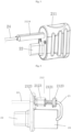
- Fig. 3 is a structural diagram one of a camera assembly according to an embodiment of the present invention
- Fig. 4 is a partial structural diagram one of the camera assembly according to an embodiment of the present invention
- Fig. 5 is a partial structural diagram two of the camera assembly according to an embodiment of the present invention
- Fig. 6 is a partial structural diagram three of the camera assembly according to an embodiment of the present invention.
- the camera assembly 2 may include a camera encapsulation portion 23.
- the camera assembly 2 includes a conducting rod 24, a grip 21, a male connector 22 disposed at the grip 21 and a first electrical wire 25.
- One end of the conducting rod 24 is connected with the grip 21 by way of direct connection or indirect connection, and the camera encapsulation portion 23 is disposed at the other end of the conducting rod 24; the first electrical wire 25 penetrates through the conducting rod 24 and the grip 21, one end of the first electrical wire 25 is directly or indirectly connected with the camera encapsulation portion 23, and the other end of the first electrical wire is directly or indirectly connected with the male connector 22.
- the first electrical wire may refer to a single electrical wire, and may also include a plurality of same or different electrical wires; meanwhile, a solution where other devices are configured in the electrical wire may not excluded.
- the male connector 22 is inserted into the receptacle 121, and the conducting rod 24 penetrates through the endoscope body inserting portion 11.
- the camera encapsulation portion 23 may be difficult to reach the pre-set position, e.g., may be difficult to accurately reach the tip of the endoscope body inserting portion 11 to capture the image in front, which further directly affects or decreases the field-of-view angle size of the image and reduces the field of view.
- an elastic compensation structure 212 is further introduced; specifically, the grip 21 includes a grip head 211 and the elastic compensation structure 212 disposed at the grip head 211.
- One end of the elastic compensation structure 212 along an access direction of the camera assembly (may also be understood as a length direction of the conducting rod 24) is directly or indirectly connected with the conducting rod 24, and the other end of the elastic compensation structure is directly or indirectly connected with the grip head 211, e.g., connected to the grip head 211 via a component cover 2122, so as to further realize the relative fixation of the positions.
- the grip head 211 is fixed relative to the handle portion 13 after the camera assembly 2 accesses and is assembled to the camera assembly access port 131; for example, a corresponding positioning structure may be configured in the handle portion 13, and the grip head 211 may be fixed to a position relative to the handle portion 13 through the positioning structure after being accessed.
- the elastic compensation structure 212 is configured to directly or indirectly push the conducting rod 24 by using an elastic force after the camera assembly 2 accesses and is assembled to the camera assembly access port 131, so that the camera encapsulation portion 23 is located at a tip of the endoscope body inserting portion, or may be understood to be located at the required position.
- the elastic force produced by the elastic compensation structure 212 may be a force produced by a force deformation of the elastic component to overcome the deformation. If the elastic component is a spring, the deformation may be, for example, a stretch or a compression; or if the elastic component is an elastic sheet or other constructs, the deformation may also be the movement of a part of components in the construction.
- the elastic compensation structure 212 includes an elastic component 2121 (e.g., a spring), a component cover 2122 and a component sleeve 2123, and a side wall of the grip head 211 close to the camera encapsulation portion (i.e., the side wall on the right of Fig.
- an elastic component 2121 e.g., a spring
- a component cover 2122 and a component sleeve 2123 e.g., a side wall of the grip head 211 close to the camera encapsulation portion (i.e., the side wall on the right of Fig.
- the elastic component through hole may be used for a part of constructs in the elastic compensation structure 212 to penetrate through, and the elastic component 2121, the component cover 2122 and the component sleeve 2123 are all disposed in an inner cavity of the grip head 211; the elastic component 2121 is connected between the component cover 2122 and the component sleeve 2123 along the access direction (i.e., the linear direction in which the camera assembly 2 accesses the camera assembly access port 131, or the length direction of the conduction rod 24).
- the access direction i.e., the linear direction in which the camera assembly 2 accesses the camera assembly access port 131, or the length direction of the conduction rod 24.
- the first electrical wire 25 penetrates through the elastic component through hole, the component sleeve 2123, and the component cover 2122 in sequence. As exemplified in Fig. 4 , the first electrical wire 25 may pass through the elastic component through hole, the component sleeve, and the component cover in sequence from right to left.
- the component sleeve 2123 is fixed relative to the conducting rod 24, e.g., may be fixedly connected to the latter by welding; the component cover 2122 is fixed relative to the grip head 211, e.g., may be fixedly connected to the latter directly or indirectly.
- the elastic compensation structure 212 further includes a component seat 2124, the component seat penetrating through the elastic component through hole, the component cover 2123 and the elastic component 2121 both being located at an inner side of the component seat 2124, and the component cover 2122 covering an end of the component seat 2124 deviated from a camera encapsulation portion 23; further, the component cover 2122 is fixed relative to the component seat 2124, and the component seat 2124 is fixed relative to the grip head 211.
- the component seat 2124 includes a flat seat body 21241 and a cylinder seat body 21242, and an end of the flat seat body 21241 being connected with the cylinder seat body 21242; the flat seat body 21241 being located outside the grip head, the cylinder seat body 21242 penetrating through the elastic component through hole, and a shape of an outer wall of the cylinder seat body 21242 being matched with an inner wall of the elastic component through hole.
- the cylinder seat body 21242 may be integral with the flat seat body 21241, and the two may be assembled as a whole. Through the flat shape at the front end, guiding functions may be exerted when the disposable endoscope body is inserted.
- the elastic compensation structure 212 further includes a sealing ring 2125 provided at one end of a docking side wall disposed at the component sleeve 2123, which may be used to prevent the liquid from entering in a non-working state.
- the encapsulation portion of the camera may be located at a required position by using the elastic force, thereby eliminating the effect caused by dimensional errors in manufacturing and assembly on the camera.
- the male connector 22 and the elastic component through hole are disposed at the same side wall of the grip head, and further accessing the grip head and docking the male connector with the receptacle may be achieved by an accessing movement in the same direction.
- the inner cavity of the grip head 211 is further provided with a male connector circuit board 26; the male connector circuit board 26 is fixed relative to the side wall, and the first electrical wire 25 is connected with the male connector 22 via the male connector circuit board 26.
- the electrical connection is achieved based on the circuit board, so that the stability of the electrical connection may be effectively guaranteed.
- the male connector 22 may be a Type C male connector, and correspondingly, the receptacle 121 may be a Type C receptacle.
- a male connector and a receptacle that are of A type may be included, or other male connectors and receptacles based on USB may be included.
- the present embodiment does not exclude the male connectors and the receptacles based on other protocols and constructs.
- the electrical connection may be achieved by inserting the male connector with the receptacle, so that a positive effect of simple assembly may be generated; meanwhile, the disposable use and discarding of the receptacle and the external connecting portion may further generate a positive effect of facilitating the overall disposal.
- a material of the conducting rod 24 is a shape memory alloy material, e.g., may be a nickel-titanium alloy. The memorized shape allows for easy bending and access.
- Fig. 7 is a partial structural diagram of the rigid endoscope according to an embodiment of the present invention.
- the endoscope body structure 1 further includes a passage tube 14 fixedly connected with the handle portion 13 and a guider 15, wherein the passage tube 14 penetrates through the handle portion 13, the endoscope body inserting portion 11 is connected to one end of the passage tube 14 (e.g., the left end of Fig. 7 ), and the guider 15 is connected to the other end of the passage tube 14 (e.g., the right end of Fig. 7 ).
- the endoscope body inserting portion 11 may be integral with the passage tube 14, and then the passage tube 14 may also be considered a part of an inserting rod 111 of the endoscope body inserting portion 11; in other examples, the endoscope body inserting portion 11 and the passage tube 14 may be assembled with each other or connected with each other by a certain process.
- the grip 21 accesses the guider 15, and the conducting rod 24 penetrates through the passage tube 14 and the endoscope body inserting portion 11 (e.g., the inserting rod 111 thereof) in sequence.
- the receptacle may also be disposed in the guider 15, and the guiding function may be exerted for inserting the camera portion that is reusable by the guider 15.
- the passage tube 14 may be fixedly connected in the handle portion 13 through the fixing seat 16, and correspondingly the handle portion 13 may be internally provided with a construct matched with the fixing seat 16. Further, through the fixing seat, it is easy for controlling the direction and the length of the endoscope body inserting portion 11 (e.g., the inserting rod 111 thereof) and the passage tube 14 to limit the positions of the instrument tube, the liquid tube and the electrical wires and the like in the endoscope body inserting portion 11 (e.g., the inserting rod 111 thereof).
- the line connecting portion 12 further includes a receptacle circuit board 124 and a second electrical wire 123, the receptacle circuit board 124 being electrically connected with the receptacle, and the receptacle circuit board is connected with the external connecting portion 122 via the second electrical wire 123 to transmit the electrical energy and/or the signal by using the second electrical wire 123; the receptacle circuit board 124 being located in the handle portion 13, and the second electrical wire 123 penetrating through a wire via disposed at the handle portion.
- a path for transmitting the electrical energy and/or the signal may be formed among the camera encapsulation portion 23, the first electrical wire 25, the male connector 22, the receptacle 121, the second electrical wire 123 and the external connecting portion 122.
- the receptacle 121 is wiredly connected with the external connecting portion 122, and the external connecting portion 122 is wiredly connected with the external equipment (e.g., a host); in other optional solutions, if the transmission of signals is required, the receptacle may also be wirelessly connected with the external connection portion, and the external connecting portion may also be wirelessly connected with the external equipment (e.g., the host). It can be seen that the external connecting portion 122 may be a wired connecting receptacle or a wireless communication component.
- Fig. 8 is a structural diagram of a handle portion according to an embodiment of the present invention.
- the flexible endoscope further includes a sterile isolation cover 3, wherein the sterile isolation cover 3 is configured to cover the camera assembly access port 131 after the camera assembly 2 accesses and is assembled to the camera assembly access port 131.
- the endoscope body structure 1 may be isolated internally.
- the sterile isolation cover 3 may include an isolation cover body 31, a connecting tape 33 and a mounting ring 32, wherein the mounting ring 32 may be connected to the endoscope body structure 1 (e.g., the handle portion 13 thereof), and the isolation cover body 31 may be connected with the mounting ring 32 through the connecting tape 33.
- the camera assembly 2 is able to be inserted into the endoscope body structure 1, and then the power supply of the camera portion 2 and the transmission of the CMOS images may be completed by connecting the line connecting portion 12 with a suitable host.
- the sterile isolation cover 3 may be buckled to a tail of the endoscope body portion 1, so that non-sterilized components are completely isolated from doctors and patients.
- the detachable sterile isolation cover 3 may not be adopted; for example, the camera assembly 2 may be directly disposed into the endoscope body structure 1, so that the external endoscope body structure 1 may be directly discarded without implementing corresponding detaching processes when the disposal is required. Further, the disassembly and disposal may be facilitated, which causes positive technical effects such as saving the time for assembly.
- Fig. 9 is a structural diagram of a handle portion according to an embodiment of the present invention
- Fig. 10 is a structural diagram of a head module according to an embodiment of the present invention
- Fig. 11 is a structural diagram of an instrument tube, a liquid tube and the head module according to an embodiment of the present invention.
- the endoscope body inserting portion 11 includes an inserting rod 111 and a head module 112, the head module 112 being disposed at one end of the inserting rod 111, and the other end of the inserting rod 111 being connected with the handle portion 13, e.g., through the passage tube 14; the head module 112 is provided with a light transmission sheet 1121 and an illumination module 1122, and the camera assembly accessing the endoscope body inserting portion may collect images externally through the light transmission sheet 1121.
- the light transmission sheet 1121 may be, for example, a glass sheet.
- the inserting rod 111 may be internally provided with a camera passage (not shown), an instrument passage (e.g., a passage formed in the instrument tube 1111) and a liquid passage (e.g., a passage formed in the liquid tube 1112), a camera through hole (e.g., a through hole behind the light transmission sheet), an instrument through hole 1124 and a liquid tube through hole 1125 penetrating through the head module 112;
- the camera passage is connected to one end of the camera through hole, the light transmission sheet is disposed at the other end of the camera through hole, the instrument passage is connected to one end of the instrument through hole, and the liquid passage is connected to one end of the liquid tube through hole;
- the handle portion is provided with an instrument access port 132 for accessing an instrument and a liquid port 133, wherein the liquid port 133 is communicated to the liquid passage; for example, the liquid tube 1113 may be exported from the inserting rod 111 and communicated to the liquid port 133.
- the liquid port 133 is provided with
- the illumination module 1122 may be, for example, an LED module, which may be disposed at the circuit board 1123, the circuit board 1123 being capable of being disposed at the head module 112.
- the inserting rod 111 may further be internally provided with an illumination electrical wire 1113, which may be directly or indirectly connected to the line connecting portion 12 (e.g., the receptacle 121), thereby achieving the power supply and/or control of the illumination module 1122.
- the disposable endoscope body structure and the reusable camera assembly may be included, wherein an electrical connection externally may be performed by the receptacle of the endoscope structure and the external connecting portion after the camera assembly accesses the camera assembly access port of the endoscope structure, so that the camera assembly itself may not be directly electrically connected externally and further the camera assembly in the present embodiment may be completely isolated sterilely, thereby effectively avoiding or reducing the security risks; since the electrical wire of the camera assembly is not required to pass through the sterile sheath (while the sterile isolation cover may not be a necessity), the difficulty in operation is further reduced, thereby facilitating the use, the disassembly and disposable discarding.
- the electrical connection may be achieved by inserting the male connector with the receptacle, so that a positive effect of simple assembly may be generated; meanwhile, the disposable use and discarding of the receptacle and the external connecting portion as a whole may further generate a positive effect of facilitating the overall disposal.
- the encapsulation portion of the camera may be located at a required position by using the elastic force, thereby eliminating the effect caused by dimensional errors in manufacturing and assembly on the camera.
Landscapes
- Health & Medical Sciences (AREA)
- Life Sciences & Earth Sciences (AREA)
- Surgery (AREA)
- Engineering & Computer Science (AREA)
- Biomedical Technology (AREA)
- Molecular Biology (AREA)
- Pathology (AREA)
- Radiology & Medical Imaging (AREA)
- Nuclear Medicine, Radiotherapy & Molecular Imaging (AREA)
- Biophysics (AREA)
- Physics & Mathematics (AREA)
- Heart & Thoracic Surgery (AREA)
- Medical Informatics (AREA)
- Optics & Photonics (AREA)
- Animal Behavior & Ethology (AREA)
- General Health & Medical Sciences (AREA)
- Public Health (AREA)
- Veterinary Medicine (AREA)
- Computer Networks & Wireless Communication (AREA)
- Endoscopes (AREA)
- Instruments For Viewing The Inside Of Hollow Bodies (AREA)
Applications Claiming Priority (1)
| Application Number | Priority Date | Filing Date | Title |
|---|---|---|---|
| PCT/CN2020/077826 WO2021174459A1 (zh) | 2020-03-04 | 2020-03-04 | 硬性内窥镜 |
Publications (4)
| Publication Number | Publication Date |
|---|---|
| EP4094663A1 EP4094663A1 (en) | 2022-11-30 |
| EP4094663A4 EP4094663A4 (en) | 2023-01-18 |
| EP4094663B1 true EP4094663B1 (en) | 2023-11-15 |
| EP4094663C0 EP4094663C0 (en) | 2023-11-15 |
Family
ID=77612817
Family Applications (1)
| Application Number | Title | Priority Date | Filing Date |
|---|---|---|---|
| EP20922925.1A Active EP4094663B1 (en) | 2020-03-04 | 2020-03-04 | Rigid endoscope |
Country Status (6)
| Country | Link |
|---|---|
| US (1) | US12279755B2 (pl) |
| EP (1) | EP4094663B1 (pl) |
| JP (1) | JP7335455B2 (pl) |
| ES (1) | ES2966344T3 (pl) |
| PL (1) | PL4094663T3 (pl) |
| WO (1) | WO2021174459A1 (pl) |
Families Citing this family (2)
| Publication number | Priority date | Publication date | Assignee | Title |
|---|---|---|---|---|
| CN118285733A (zh) * | 2024-04-02 | 2024-07-05 | 杭州思康新医疗科技有限公司 | 一种内窥镜 |
| CN119405248B (zh) * | 2025-01-08 | 2025-05-23 | 湖南省华芯医疗器械有限公司 | 内窥镜及其可抛弃段 |
Family Cites Families (22)
| Publication number | Priority date | Publication date | Assignee | Title |
|---|---|---|---|---|
| JP3231399B2 (ja) * | 1992-06-10 | 2001-11-19 | オリンパス光学工業株式会社 | 内視鏡撮像装置 |
| DE19715507C1 (de) * | 1997-04-14 | 1999-02-04 | Storz Karl Gmbh & Co | Medizinisches Instrument mit einem tubusartigen Element und einem dazu abgewinkelten Griff, insbesondere Mediastinoskop, Laryngoskop, Divertikuloskop |
| US20090264706A1 (en) * | 2008-04-16 | 2009-10-22 | Bala John L | Disposable interchangeable angle light guide system |
| US10029079B2 (en) * | 2011-10-18 | 2018-07-24 | Treble Innovations | Endoscopic peripheral |
| WO2014155793A1 (ja) * | 2013-03-28 | 2014-10-02 | オリンパスメディカルシステムズ株式会社 | 内視鏡 |
| US10188411B2 (en) * | 2013-04-16 | 2019-01-29 | Calcula Technologies, Inc. | Everting balloon for medical devices |
| JP5963977B1 (ja) * | 2014-08-21 | 2016-08-03 | オリンパス株式会社 | 硬性鏡セット |
| US10524636B2 (en) * | 2015-02-23 | 2020-01-07 | Uroviu Corp. | Handheld surgical endoscope |
| US20160302657A1 (en) * | 2015-04-15 | 2016-10-20 | Jacqueline Marie Hussey | Dual channeled gynecologic speculum with specimen collection and diagnostic imaging capabilities |
| CN105147229B (zh) | 2015-09-09 | 2017-07-04 | 宁波舜宇光电信息有限公司 | 内窥镜装置及其应用 |
| US10433822B2 (en) * | 2016-04-22 | 2019-10-08 | Welch Allyn, Inc. | System and method for medical diagnostics |
| CN114098601B (zh) | 2016-06-21 | 2025-11-28 | 安多卓思公司 | 具有与不同的视频数据信号源连接的多个连接接口的内窥镜系统 |
| CN106821286A (zh) | 2016-12-20 | 2017-06-13 | 杭州好克光电仪器有限公司 | 一次性电子内窥镜 |
| CN107049215A (zh) | 2017-05-19 | 2017-08-18 | 成都聚像光学技术有限公司 | 内窥镜系统 |
| WO2019118484A2 (en) | 2017-12-12 | 2019-06-20 | Convergascent Llc | Multi-use endoscopes and associated systems and methods |
| EP3498203B1 (de) | 2017-12-12 | 2021-11-03 | Erbe Elektromedizin GmbH | Sondenapplikator |
| US12279748B2 (en) * | 2018-02-14 | 2025-04-22 | Suzhou Acuvu Medical Technology Co. Ltd | Endoscopy system with off-center direction of view |
| EP3758575B1 (en) * | 2018-03-13 | 2024-02-07 | Meditrina, Inc. | Endoscope and method of use |
| CN209186637U (zh) * | 2018-12-27 | 2019-08-02 | 苏州森美特塑业制品有限公司 | 内窥镜套管、内窥镜组件以及手持式内窥镜 |
| CN110251057A (zh) | 2019-07-04 | 2019-09-20 | 苏州新光维医疗科技有限公司 | 内窥镜 |
| CN110215180B (zh) * | 2019-07-04 | 2024-06-07 | 上海安清医疗器械有限公司 | 硬性内窥镜装置 |
| US11832786B2 (en) * | 2020-01-16 | 2023-12-05 | Meditrina, Inc. | Endoscopic imaging and control systems and methods for use in diagnostic and therapeutic medical procedures |
-
2020
- 2020-03-04 JP JP2022549435A patent/JP7335455B2/ja active Active
- 2020-03-04 ES ES20922925T patent/ES2966344T3/es active Active
- 2020-03-04 US US17/801,256 patent/US12279755B2/en active Active
- 2020-03-04 WO PCT/CN2020/077826 patent/WO2021174459A1/zh not_active Ceased
- 2020-03-04 PL PL20922925.1T patent/PL4094663T3/pl unknown
- 2020-03-04 EP EP20922925.1A patent/EP4094663B1/en active Active
Also Published As
| Publication number | Publication date |
|---|---|
| WO2021174459A1 (zh) | 2021-09-10 |
| US20230103245A1 (en) | 2023-03-30 |
| EP4094663A4 (en) | 2023-01-18 |
| ES2966344T3 (es) | 2024-04-22 |
| EP4094663A1 (en) | 2022-11-30 |
| PL4094663T3 (pl) | 2024-03-11 |
| JP2023514320A (ja) | 2023-04-05 |
| EP4094663C0 (en) | 2023-11-15 |
| JP7335455B2 (ja) | 2023-08-29 |
| US12279755B2 (en) | 2025-04-22 |
Similar Documents
| Publication | Publication Date | Title |
|---|---|---|
| EP3970596B1 (en) | Endoscopic device | |
| EP1862108A2 (en) | Optically coupled endoscope with microchip | |
| EP4226839B1 (en) | Soft endoscopy system | |
| EP3995068B1 (en) | Rigid endoscope device | |
| CN113795187A (zh) | 具有集成视觉和照明的单次使用内窥镜、套管和闭塞器 | |
| CN111202487A (zh) | 软性内窥镜 | |
| EP4094663B1 (en) | Rigid endoscope | |
| EP4094670B1 (en) | Flexible endoscope | |
| WO2013008555A1 (ja) | 加熱機能付きトロッカー及びそのシステム | |
| US11503989B2 (en) | Multi-channel system | |
| CN211961979U (zh) | 软性内窥镜 | |
| US12484765B2 (en) | Modular endoscope with a bayonet connection | |
| CN111184496A (zh) | 硬性内窥镜 | |
| CN212118096U (zh) | 硬性内窥镜 | |
| CN210749132U (zh) | 硬性内窥镜装置 | |
| CN210300918U (zh) | 内窥镜装置 | |
| CN204351789U (zh) | 便携式电子弯管喉镜 | |
| JP2008188130A (ja) | 電子内視鏡の先端部 |
Legal Events
| Date | Code | Title | Description |
|---|---|---|---|
| STAA | Information on the status of an ep patent application or granted ep patent |
Free format text: STATUS: THE INTERNATIONAL PUBLICATION HAS BEEN MADE |
|
| PUAI | Public reference made under article 153(3) epc to a published international application that has entered the european phase |
Free format text: ORIGINAL CODE: 0009012 |
|
| STAA | Information on the status of an ep patent application or granted ep patent |
Free format text: STATUS: REQUEST FOR EXAMINATION WAS MADE |
|
| 17P | Request for examination filed |
Effective date: 20220824 |
|
| AK | Designated contracting states |
Kind code of ref document: A1 Designated state(s): AL AT BE BG CH CY CZ DE DK EE ES FI FR GB GR HR HU IE IS IT LI LT LU LV MC MK MT NL NO PL PT RO RS SE SI SK SM TR |
|
| A4 | Supplementary search report drawn up and despatched |
Effective date: 20221219 |
|
| RIC1 | Information provided on ipc code assigned before grant |
Ipc: A61B 1/045 20060101ALI20221213BHEP Ipc: A61B 1/04 20060101ALI20221213BHEP Ipc: A61B 1/00 20060101AFI20221213BHEP |
|
| DAV | Request for validation of the european patent (deleted) | ||
| DAX | Request for extension of the european patent (deleted) | ||
| GRAP | Despatch of communication of intention to grant a patent |
Free format text: ORIGINAL CODE: EPIDOSNIGR1 |
|
| STAA | Information on the status of an ep patent application or granted ep patent |
Free format text: STATUS: GRANT OF PATENT IS INTENDED |
|
| INTG | Intention to grant announced |
Effective date: 20230628 |
|
| RAP3 | Party data changed (applicant data changed or rights of an application transferred) |
Owner name: ANQING MEDICAL CO., LTD |
|
| GRAS | Grant fee paid |
Free format text: ORIGINAL CODE: EPIDOSNIGR3 |
|
| GRAA | (expected) grant |
Free format text: ORIGINAL CODE: 0009210 |
|
| STAA | Information on the status of an ep patent application or granted ep patent |
Free format text: STATUS: THE PATENT HAS BEEN GRANTED |
|
| AK | Designated contracting states |
Kind code of ref document: B1 Designated state(s): AL AT BE BG CH CY CZ DE DK EE ES FI FR GB GR HR HU IE IS IT LI LT LU LV MC MK MT NL NO PL PT RO RS SE SI SK SM TR |
|
| REG | Reference to a national code |
Ref country code: CH Ref legal event code: EP Ref country code: GB Ref legal event code: FG4D |
|
| REG | Reference to a national code |
Ref country code: DE Ref legal event code: R096 Ref document number: 602020021297 Country of ref document: DE |
|
| REG | Reference to a national code |
Ref country code: IE Ref legal event code: FG4D |
|
| U01 | Request for unitary effect filed |
Effective date: 20231201 |
|
| U07 | Unitary effect registered |
Designated state(s): AT BE BG DE DK EE FI FR IT LT LU LV MT NL PT SE SI Effective date: 20231207 |
|
| REG | Reference to a national code |
Ref country code: NO Ref legal event code: T2 Effective date: 20231115 |
|
| REG | Reference to a national code |
Ref country code: GR Ref legal event code: EP Ref document number: 20230402485 Country of ref document: GR Effective date: 20240110 |
|
| U20 | Renewal fee for the european patent with unitary effect paid |
Year of fee payment: 5 Effective date: 20240207 |
|
| PG25 | Lapsed in a contracting state [announced via postgrant information from national office to epo] |
Ref country code: IS Free format text: LAPSE BECAUSE OF FAILURE TO SUBMIT A TRANSLATION OF THE DESCRIPTION OR TO PAY THE FEE WITHIN THE PRESCRIBED TIME-LIMIT Effective date: 20240315 |
|
| REG | Reference to a national code |
Ref country code: ES Ref legal event code: FG2A Ref document number: 2966344 Country of ref document: ES Kind code of ref document: T3 Effective date: 20240422 |
|
| PG25 | Lapsed in a contracting state [announced via postgrant information from national office to epo] |
Ref country code: IS Free format text: LAPSE BECAUSE OF FAILURE TO SUBMIT A TRANSLATION OF THE DESCRIPTION OR TO PAY THE FEE WITHIN THE PRESCRIBED TIME-LIMIT Effective date: 20240315 |
|
| PG25 | Lapsed in a contracting state [announced via postgrant information from national office to epo] |
Ref country code: RS Free format text: LAPSE BECAUSE OF FAILURE TO SUBMIT A TRANSLATION OF THE DESCRIPTION OR TO PAY THE FEE WITHIN THE PRESCRIBED TIME-LIMIT Effective date: 20231115 Ref country code: HR Free format text: LAPSE BECAUSE OF FAILURE TO SUBMIT A TRANSLATION OF THE DESCRIPTION OR TO PAY THE FEE WITHIN THE PRESCRIBED TIME-LIMIT Effective date: 20231115 |
|
| PG25 | Lapsed in a contracting state [announced via postgrant information from national office to epo] |
Ref country code: SK Free format text: LAPSE BECAUSE OF FAILURE TO SUBMIT A TRANSLATION OF THE DESCRIPTION OR TO PAY THE FEE WITHIN THE PRESCRIBED TIME-LIMIT Effective date: 20231115 |
|
| PG25 | Lapsed in a contracting state [announced via postgrant information from national office to epo] |
Ref country code: SM Free format text: LAPSE BECAUSE OF FAILURE TO SUBMIT A TRANSLATION OF THE DESCRIPTION OR TO PAY THE FEE WITHIN THE PRESCRIBED TIME-LIMIT Effective date: 20231115 Ref country code: SK Free format text: LAPSE BECAUSE OF FAILURE TO SUBMIT A TRANSLATION OF THE DESCRIPTION OR TO PAY THE FEE WITHIN THE PRESCRIBED TIME-LIMIT Effective date: 20231115 Ref country code: RO Free format text: LAPSE BECAUSE OF FAILURE TO SUBMIT A TRANSLATION OF THE DESCRIPTION OR TO PAY THE FEE WITHIN THE PRESCRIBED TIME-LIMIT Effective date: 20231115 |
|
| REG | Reference to a national code |
Ref country code: DE Ref legal event code: R097 Ref document number: 602020021297 Country of ref document: DE |
|
| PLBE | No opposition filed within time limit |
Free format text: ORIGINAL CODE: 0009261 |
|
| STAA | Information on the status of an ep patent application or granted ep patent |
Free format text: STATUS: NO OPPOSITION FILED WITHIN TIME LIMIT |
|
| 26N | No opposition filed |
Effective date: 20240819 |
|
| PG25 | Lapsed in a contracting state [announced via postgrant information from national office to epo] |
Ref country code: MC Free format text: LAPSE BECAUSE OF FAILURE TO SUBMIT A TRANSLATION OF THE DESCRIPTION OR TO PAY THE FEE WITHIN THE PRESCRIBED TIME-LIMIT Effective date: 20231115 |
|
| PG25 | Lapsed in a contracting state [announced via postgrant information from national office to epo] |
Ref country code: MC Free format text: LAPSE BECAUSE OF FAILURE TO SUBMIT A TRANSLATION OF THE DESCRIPTION OR TO PAY THE FEE WITHIN THE PRESCRIBED TIME-LIMIT Effective date: 20231115 |
|
| PGFP | Annual fee paid to national office [announced via postgrant information from national office to epo] |
Ref country code: PL Payment date: 20241216 Year of fee payment: 6 |
|
| U20 | Renewal fee for the european patent with unitary effect paid |
Year of fee payment: 6 Effective date: 20250205 |
|
| PGFP | Annual fee paid to national office [announced via postgrant information from national office to epo] |
Ref country code: GR Payment date: 20250213 Year of fee payment: 6 |
|
| PGFP | Annual fee paid to national office [announced via postgrant information from national office to epo] |
Ref country code: CZ Payment date: 20250219 Year of fee payment: 6 |
|
| PGFP | Annual fee paid to national office [announced via postgrant information from national office to epo] |
Ref country code: ES Payment date: 20250408 Year of fee payment: 6 |
|
| PGFP | Annual fee paid to national office [announced via postgrant information from national office to epo] |
Ref country code: CH Payment date: 20250401 Year of fee payment: 6 |
|
| PG25 | Lapsed in a contracting state [announced via postgrant information from national office to epo] |
Ref country code: CY Free format text: LAPSE BECAUSE OF FAILURE TO SUBMIT A TRANSLATION OF THE DESCRIPTION OR TO PAY THE FEE WITHIN THE PRESCRIBED TIME-LIMIT; INVALID AB INITIO Effective date: 20200304 |
|
| PG25 | Lapsed in a contracting state [announced via postgrant information from national office to epo] |
Ref country code: HU Free format text: LAPSE BECAUSE OF FAILURE TO SUBMIT A TRANSLATION OF THE DESCRIPTION OR TO PAY THE FEE WITHIN THE PRESCRIBED TIME-LIMIT; INVALID AB INITIO Effective date: 20200304 |
|
| PG25 | Lapsed in a contracting state [announced via postgrant information from national office to epo] |
Ref country code: TR Free format text: LAPSE BECAUSE OF FAILURE TO SUBMIT A TRANSLATION OF THE DESCRIPTION OR TO PAY THE FEE WITHIN THE PRESCRIBED TIME-LIMIT Effective date: 20231115 |
|
| U20 | Renewal fee for the european patent with unitary effect paid |
Year of fee payment: 7 Effective date: 20260209 |
|
| REG | Reference to a national code |
Ref country code: CH Ref legal event code: U11 Free format text: ST27 STATUS EVENT CODE: U-0-0-U10-U11 (AS PROVIDED BY THE NATIONAL OFFICE) Effective date: 20260401 |
|
| PGFP | Annual fee paid to national office [announced via postgrant information from national office to epo] |
Ref country code: GB Payment date: 20260209 Year of fee payment: 7 |
|
| PGFP | Annual fee paid to national office [announced via postgrant information from national office to epo] |
Ref country code: NO Payment date: 20260210 Year of fee payment: 7 Ref country code: IE Payment date: 20260206 Year of fee payment: 7 |