EP4093945B1 - Turbomaschinenteil oder anordnung von bauteilen - Google Patents
Turbomaschinenteil oder anordnung von bauteilen Download PDFInfo
- Publication number
- EP4093945B1 EP4093945B1 EP21705587.0A EP21705587A EP4093945B1 EP 4093945 B1 EP4093945 B1 EP 4093945B1 EP 21705587 A EP21705587 A EP 21705587A EP 4093945 B1 EP4093945 B1 EP 4093945B1
- Authority
- EP
- European Patent Office
- Prior art keywords
- blade
- fin
- tangent
- angle
- blades
- Prior art date
- Legal status (The legal status is an assumption and is not a legal conclusion. Google has not performed a legal analysis and makes no representation as to the accuracy of the status listed.)
- Active
Links
Images


Classifications
-
- F—MECHANICAL ENGINEERING; LIGHTING; HEATING; WEAPONS; BLASTING
- F01—MACHINES OR ENGINES IN GENERAL; ENGINE PLANTS IN GENERAL; STEAM ENGINES
- F01D—NON-POSITIVE DISPLACEMENT MACHINES OR ENGINES, e.g. STEAM TURBINES
- F01D5/00—Blades; Blade-carrying members; Heating, heat-insulating, cooling or antivibration means on the blades or the members
- F01D5/12—Blades
- F01D5/14—Form or construction
- F01D5/141—Shape, i.e. outer, aerodynamic form
- F01D5/142—Shape, i.e. outer, aerodynamic form of the blades of successive rotor or stator blade-rows
- F01D5/143—Contour of the outer or inner working fluid flow path wall, i.e. shroud or hub contour
-
- F—MECHANICAL ENGINEERING; LIGHTING; HEATING; WEAPONS; BLASTING
- F01—MACHINES OR ENGINES IN GENERAL; ENGINE PLANTS IN GENERAL; STEAM ENGINES
- F01D—NON-POSITIVE DISPLACEMENT MACHINES OR ENGINES, e.g. STEAM TURBINES
- F01D5/00—Blades; Blade-carrying members; Heating, heat-insulating, cooling or antivibration means on the blades or the members
- F01D5/12—Blades
- F01D5/14—Form or construction
- F01D5/141—Shape, i.e. outer, aerodynamic form
-
- F—MECHANICAL ENGINEERING; LIGHTING; HEATING; WEAPONS; BLASTING
- F05—INDEXING SCHEMES RELATING TO ENGINES OR PUMPS IN VARIOUS SUBCLASSES OF CLASSES F01-F04
- F05D—INDEXING SCHEME FOR ASPECTS RELATING TO NON-POSITIVE-DISPLACEMENT MACHINES OR ENGINES, GAS-TURBINES OR JET-PROPULSION PLANTS
- F05D2220/00—Application
- F05D2220/30—Application in turbines
-
- F—MECHANICAL ENGINEERING; LIGHTING; HEATING; WEAPONS; BLASTING
- F05—INDEXING SCHEMES RELATING TO ENGINES OR PUMPS IN VARIOUS SUBCLASSES OF CLASSES F01-F04
- F05D—INDEXING SCHEME FOR ASPECTS RELATING TO NON-POSITIVE-DISPLACEMENT MACHINES OR ENGINES, GAS-TURBINES OR JET-PROPULSION PLANTS
- F05D2240/00—Components
- F05D2240/20—Rotors
- F05D2240/30—Characteristics of rotor blades, i.e. of any element transforming dynamic fluid energy to or from rotational energy and being attached to a rotor
-
- F—MECHANICAL ENGINEERING; LIGHTING; HEATING; WEAPONS; BLASTING
- F05—INDEXING SCHEMES RELATING TO ENGINES OR PUMPS IN VARIOUS SUBCLASSES OF CLASSES F01-F04
- F05D—INDEXING SCHEME FOR ASPECTS RELATING TO NON-POSITIVE-DISPLACEMENT MACHINES OR ENGINES, GAS-TURBINES OR JET-PROPULSION PLANTS
- F05D2250/00—Geometry
- F05D2250/70—Shape
- F05D2250/73—Shape asymmetric
-
- Y—GENERAL TAGGING OF NEW TECHNOLOGICAL DEVELOPMENTS; GENERAL TAGGING OF CROSS-SECTIONAL TECHNOLOGIES SPANNING OVER SEVERAL SECTIONS OF THE IPC; TECHNICAL SUBJECTS COVERED BY FORMER USPC CROSS-REFERENCE ART COLLECTIONS [XRACs] AND DIGESTS
- Y02—TECHNOLOGIES OR APPLICATIONS FOR MITIGATION OR ADAPTATION AGAINST CLIMATE CHANGE
- Y02T—CLIMATE CHANGE MITIGATION TECHNOLOGIES RELATED TO TRANSPORTATION
- Y02T50/00—Aeronautics or air transport
- Y02T50/60—Efficient propulsion technologies, e.g. for aircraft
Definitions
- the present invention relates to a turbomachine part comprising blades and a platform having a non-axisymmetric surface.
- a hub surface is locally non-axisymmetric if the radius of the hub at the level of the zone varies according to the angle that this radius forms with a vertical axis perpendicular to the axis of revolution of the means.
- a hub surface is locally axisymmetric if the radius of the hub at the level of the zone is constant regardless of the angle that this radius forms with a vertical axis perpendicular to the axis of revolution of the means.
- the non-axisymmetric vein defines a globally annular surface of a three-dimensional space (a "slice" of the hub).
- FIG 2 represents the effect of an incoming flow 201 on the passage flow 202.
- This passage flow 202 is generated by the pressure gradient between the pressure face (intrados) and the depression face (extrados) of a blade.
- This passage flow 202 impacts the extrados of the blade.
- a "corner flow" 203 then occurs. in English terminology) of the boundary layer on the blade.
- This corner separation 203 generates pressure losses. The objective of the fins is then to reduce these corner separation effects 203 on the blade by acting directly on the passage flow 202.
- the patent application is known WO2015092306A1 in which fins are added to the hub or casing of a turbomachine. These fins have a substantially triangular cross-section and allow the optimization of the performance of the turbomachine for a range of operating points of the latter. It would however be interesting to obtain fins allowing an enlargement of the range of operating points for which the performances are optimized. It would be particularly interesting to improve the performances of the turbomachine when the angle of incidence of the flow, arriving on the blades, is high, that is to say with an upstream flow which arrives with an angle of incidence, higher than that of the nominal case.
- the present invention solves the technical problem of obtaining a turbomachine blade making it possible to improve the performance of the turbomachine for a wide operating range.
- a part of a turbomachine comprising at least first and second blades, and a platform from which the blades extend.
- the platform has between the intrados of the first blade and the extrados of the second blade a non-axisymmetric surface defining at least one fin.
- the part is characterized in that a cross-section of the fin is asymmetrical.
- the asymmetrical cross-section comprises two oblique faces meeting on a dorsal edge, a face oriented towards the intrados of the first blade having a steeper slope than a face oriented towards the extrados of the second blade.
- a first tangent to the asymmetrical cross-section of the fin at an inflection point of the intrados-facing face of the first blade and a second tangent to the surface at the intersection of the first tangent and the surface intersect at a first angle.
- a third tangent to the cross-section of the fin at an inflection point of the extrados-facing face of the second blade and a fourth tangent to the surface at the intersection of the third tangent and the surface intersect at a second angle.
- the first angle is smaller than the second angle.
- the first angle is between 90° and 130° and the second angle is less than 160°.
- a longitudinal section of the fin comprises a first portion in which a distance between the dorsal edge and the surface is increasing and a second portion in which the distance is decreasing.
- a tangent to the longitudinal section at a mid-height point of the first part and the surface intersect forming a fourth angle in particular between 90° and 160.
- a tangent to the longitudinal section at a mid-height point of the second part and the surface intersect forming a fifth angle in particular between 90° and 160.
- the leading position of the winglet is located between -10% and 50% of the relative length of a blade chord extending from a leading edge to a trailing edge of the blade.
- the distance between the leading position of the winglet and the extrados of the second blade is between 5% and 95% of the distance between the intrados of the first blade and the extrados of the second blade.
- a tangent to a chord of the fin at the fin attack position and a tangent to the chord of the blade at a blade attack position intersect forming a sixth angle between -10° and +10°.
- the fin has a length between 5% and 120% of the length of the blade chord.
- the fin has a width between 1% and 40% of the distance between the intrados of the first blade and the extrados of the second blade.
- the platform has an annular shape along which a plurality of blades are regularly arranged.
- the platform includes the same non-axisymmetric surface between each pair of consecutive blades.
- Another aspect relates to a compressor impeller or rectifier comprising the part or part assembly described above.
- Another aspect relates to a turbomachine comprising a part or set of parts as described above.
- Another aspect relates to an aircraft comprising a turbomachine as described above.
- the present turbomachine part 1 has at least two consecutive blades 3E, 31 and a platform 2 from which the blades 3E, 3I extend.
- the term platform is here interpreted in the broad sense and generally designates any element of a turbomachine on which blades 3E, 3I are capable of being mounted (by extending radially) and having an internal/external wall against which the air circulates.
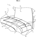
- the platform 2 can be in one piece (and thus support all of the blades of the part 1), or formed from a plurality of elementary members each supporting a single blade 3E, 3I (a “foot” of the blade) so as to constitute a blade of the type represented by the figure 3
- the platform 2 may comprise a platform part for each of the blades 3E, 3I in an advantageous embodiment which will be described later.
- the platform 2 can delimit a radially inner wall of the part 1 (the gas passes around) by defining a hub, and/or a radially outer wall of the part 1 (the gas passes inside, the blades 3I, 3E extend towards the center) by then defining a casing of the part 1.
- the same part 1 can simultaneously comprise these two types of platform 2.
- the part 1 can be of many types, in particular a rotor stage (DAM for “Disque Aubagé Monobloc”, or bladed wheel, depending on whether or not the assembly is integral) or a stator stage (fixed rectifier, or with moving blades VSV “Variable Stator Vane” in English terminology), in particular at the level of the secondary flow inlet which comprises fixed blades used to straighten the flow (OGV straightener, “Outlet Guide Vane” in Anglo-Saxon terminology), see figure 1 already introduced.
- DAM rotor stage
- stator stage fixed rectifier, or with moving blades VSV “Variable Stator Vane” in English terminology
- the present part 1 is distinguished by a particular geometry (non-axisymmetric) of a surface S of a platform 2 of the part 1, of which we observe an example of advantageous modeling on the figures 3 And 4 .
- the surface S extends between two blades 3E, 3I (only one of which is visible on each of the figures 3 And 4 to better observe the surface S. We nevertheless note the trace of the missing blade in each case), which limits it laterally.
- the surface S is in fact a part of a larger surface defining a substantially toric shape around the part 1.
- the wall is made up of a plurality of identical surfaces duplicated between each pair of blades 3E, 3I.
- the surface S' visible on the figure 4 is thus a duplication of the surface S.
- the platform 2 is composed of a plurality of elementary members, each being a foot supporting a blade 3E, 3I with which it forms a vane.
- Each of these blade feet (called “platform parts” in the remainder of this description) thus extends on either side of the blade 3E, 3I, hence the fact that the surface S comprises juxtaposed surfaces associated with two separate blade feet.
- the part 1 is then a set of at least two blades (blade/blade foot assembly) juxtaposed.
- integrated platforms as opposed to “added” platforms, i.e. independent of the blades (the surface S can then be made up of a single element). It will be understood that the present invention is not limited to any particular structure of the platform 2.
- the surface S is limited upstream by a first extremal plane, the “Separation plane” PS and downstream by a second extremal plane, the “Connection plane” PR, each of which defines an axisymmetric, continuous contour with a continuous derivative (the curve corresponding to the intersection between each of the planes PR and PS and the surface of the part 1 as a whole is closed and forms a loop).
- the surface S has a substantially parallelogrammic shape and extends continuously between the two extremal planes PS, PR, and the two blades 3E, 3I of a pair of consecutive blades.
- One of the blades of this pair of blades is the first blade 3I, or intrados blade. It in fact presents its intrados to the surface S.
- the other blade is the second blade 3E, or extrados blade. It presents its intrados to the surface S.
- Each “second blade” 3E is the “first blade” 3I of a neighboring surface such as the surface S' in the figure 4 (since each blade 3E, 3I has an intrados
- the non-axisymmetric surface S of the present part is remarkable in that it defines at least one fin 4 which has a transverse section (section taken along a transverse plane), asymmetrical.
- transverse plane is meant a plane particulate to a tangent to a chord of the fin 4 at the point of the chord where the section is made.
- the section of this fin is shown on the figure 5 .
- asymmetric cross section we mean that the cross section, as such, does not have any plane or axis of symmetry.
- the fin 4 has the asymmetrical section over at least 50% of a length of a chord of the fin. More particularly, it is possible that the fin does not have this asymmetrical section in the area near its leading edge or in the area near its trailing edge.
- This fin with an asymmetrical section makes it possible to block the flow of passage and reduces the generation of the fin wake.
- the section, and in particular its profile, of the fin advantageously has two oblique faces F1 and F2 meeting on a dorsal edge AD, a face F1 oriented towards the intrados of the first blade 3I having a steeper slope than a face F2 oriented towards the extrados of the second blade 3E.
- These two oblique faces F1 and F2 meet on the dorsal edge AD, either by an angle or by a tangent connection.
- the two faces themselves connect to the vein (rest of the surface S) either by an angle or by a tangent connection.
- the face therefore designates the entire slope of the fin extending between the dorsal edge AD and the connection point of the slope or face with the surface S.
- the slope of a face is not necessarily constant and can vary between the connection point between the face, and the surface and the dorsal edge AD.
- a face A is steeper than a face B if the average slope, given by the ratio between the height of the dorsal edge AD and the distance between the projection of the dorsal edge AD on the hub and the point on the hub where the face meets the surface S, is greater for face A than for face B.
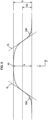
- FIG. 6 represents the difference between a fin having a symmetrical profile P1 in broken lines and a fin having a non-symmetrical profile P2 in continuous lines.
- the effect of the passing flow on the corner boundary layer is shown in the figure 7-a .
- the azimuthal pressure gradient creates a flow from the intrados of the first blade 3I to the extrados of the second blade 3E (passage vortex P+, P-). In doing so, it deforms the hub boundary layer, which has the effect of thinning it on the intrados side of the blade 3I and thickening it on the extrados side of the blade 3E. In this figure this thickening is represented in the circle EP.
- the theoretical boundary layer CL theo and the practical boundary layer with the effect of the passage vortex CL prat1 are also represented. This results in an accumulation of fluid with low momentum, more sensitive to disturbances coming from the main flow and more likely to detach.
- FIG. 7-b represents the same phenomenon, this time with the addition of a fin between blades 3I and 3E.
- New pressure gradients are established and passage vortices (P+, P-) have a lower amplitude.
- This fin also offers the advantage of refining the corner boundary layer of blade 3E (CL prat2 ) compared to the case where there is no fin (CL prat1 ). This boundary layer is then more resistant to separation and generates fewer losses.
- the proposed fin allows the intrados to extrados flow to be limited as much as possible in order to reduce the size of the corner boundary layer.
- the steep slope of the fin on the intrados side of the first blade 3I thus blocks this flow.
- d 1 represents a first tangent to the profile of the fin at a point of inflection A of the face oriented towards the intrados of the first blade 3I.
- d 2 represents a second tangent to the surface S at a point of intersection of the first tangent d 1 and the surface S.
- ⁇ 1 represents a first angle between the first tangent d 1 and the second tangent d 2 .
- d 1 ' represents a third tangent to the profile of the fin at a point of inflection of the face oriented towards the extrados of the second blade 3E.
- d 2 ' represents a fourth tangent to the surface at the intersection of the third tangent d 1 ' and the surface S.
- ⁇ 4 represents a second angle between the third tangent d 1 ' and the fourth tangent d 2 '.
- the first angle ⁇ 1 is smaller than the second angle ⁇ 4 .
- the first angle ⁇ 1 is between 90° and 130° and the second angle ⁇ 4 is less than 160°.
- a face inflection point is a point at which the concavity of the face is reversed. The concavity of the face then changes from “convex" to “concave” (or vice versa).
- This inflection point is the point where the derivative of the face profile changes sign.
- the face is represented by an affine function, the tangents to the face at all points on the face are identical, so in this case the inflection point is any point on the face.
- the axial position of the fin and its dimensions are defined so as to limit the pressure losses generated by the presence of the fin.
- Each fin 4 may further have beveled ends as seen in the figures 2 And 3 .
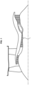
- There figure 8 represents a longitudinal section of the fin 4, on this figure 8 the fin has two beveled ends.
- This section is represented via a cut passing through the dorsal edge AD of the fin and the axis of revolution of the stator or rotor supporting the fin and the blades.
- This figure therefore shows the height h of the dorsal edge AD of the fin 4 relative to the surface S, as a function of the axial direction.
- This section has two parts, in the first part a profile of the section is generally increasing and in the second part the profile of the section is generally decreasing.
- the mid-height point is defined as the point of the section at which the height of the fin 4 is equal to half the maximum height of the fin 4.
- d 3 represents a tangent to the section at the mid-height point of the first part. This tangent d 3 intersects the surface S forming a fourth angle denoted ⁇ BA .
- d 4 represents a tangent to the section at the mid-height point of the second part. This tangent d 4 intersects the surface S forming a fifth angle denoted ⁇ BF .
- the fourth angle and the fifth angle are between 90° and 160.
- the fin 4 has a width of between 1% and 40% of the distance between the intrados of the first blade 3I and the extrados of the second blade 3E.
- the width considered here is the maximum width of the base of the fin 4 (which is substantially constant, except at the level of the leading and trailing bevels).
- This width and the distance between the intrados of the first blade 3I and the extrados of the second blade 3E are preferably assessed according to planes parallel to the extreme planes PS, PR which are visible on the figures 3 And 4 .
- the fin 4 has a length between 5% and 120% of the chord length of the adjacent blade (3E or 3I). This length of the fin offers the advantage of minimizing the drag generated by the fin 4.
- chord of a blade is a line from the leading edge to the trailing edge of the blade.
- the location of the fin 4 is in particular defined by its upstream extreme point, which is an attack position on the surface S, from which the fin 4 extends (in particular following the skeleton of the blades 3I, 3E).
- the attack position of fin 4 is defined in the reference frame of the figure 9 by coordinates X BA and Y BA . These coordinates are respectively an axial coordinate and an azimuthal coordinate of the attack position of the fin.
- This therefore makes it possible to define the positions X ups and X dws extremal of the attack position of the fin 4.
- the axial attack position is located between -10% and 50% of the relative length of the blade chord 3I, 3E (i.e. X BA belongs to [-0.1; 0.5]).
- the fin 4 is not necessarily included between the leading edges BA and trailing edges BF of the blades 3I, 3E and can extend axially downstream of the trailing edge BF or upstream of the leading edge BA.
- the azimuthal attack position is located at a distance from the extrados of the second blade 3E of between 5% and 95% of the channel width (i.e. Y BA belongs to [0.05; 0.95]).
- FIG 10 represents a tangent d 3 to a chord of the fin 4 at the attack position of the fin and a tangent d 3 ' to the chord of the blade at a blade attack position (3E or 3I).
- the two tangents intersect, forming a sixth angle a between -10° and +10°.
- the different blades are generally arranged so that the tangents to the blade chord at the blade attack positions are parallel.
- the sixth angle a can be calculated from the first blade 3I or the second blade 3E.
- the sixth angle a is calculated from the blade closest to the fin in order to avoid mismatches in incidence. By default, it is calculated relative to the second blade 3E.
- the figure 3 represents a one-fin solution 4, and the figure 4 with two fins, but it will be understood that the invention is not limited to this case.
- each fin 4 has a trace (i.e. a trajectory) corresponding to the mean line of skeletons of the first and second blades 3I, 3E. Most often, all the blades have the same skeleton, which is why all the fins 4 and blades 3I, 3E have a similar curvature, but it will be understood that the invention is not limited to this case.
- Part 1 may form a bladed wheel or a compressor rectifier.
- the bladed wheel is made up of a set of parts, as is a rectifier crown.
- a compressor rectifier is advantageously made up of a single part.
Landscapes
- Engineering & Computer Science (AREA)
- Physics & Mathematics (AREA)
- Fluid Mechanics (AREA)
- Mechanical Engineering (AREA)
- General Engineering & Computer Science (AREA)
- Structures Of Non-Positive Displacement Pumps (AREA)
- Turbine Rotor Nozzle Sealing (AREA)
Claims (14)
- Turbomaschinenteil, umfassend:- mindestens eine erste und eine zweite Schaufel (3I, 3E), und- eine Plattform (2), von der aus sich die Schaufeln (3I, 3E) erstrecken,- wobei die Plattform (2) zwischen der Druckseite der ersten Schaufel (31) und der Saugseite der zweiten Schaufel (3E) eine nicht axialsymmetrische Oberfläche (S) aufweist, die mindestens eine Rippe (4) definiert,- ein Querschnitt der Rippe (4) asymmetrisch ist, wobei der asymmetrische Querschnitt zwei schräge Seiten (F1, F2) umfasst, die an einer Rückenkante (AD) aufeinandertreffen,dadurch gekennzeichnet, dass eine Seite (F1), die zur Druckseite der ersten Schaufel (31) orientiert ist, eine steilere Steigung als eine Seite (F2), die zur Saugseite der zweiten Schaufel (3E) orientiert ist, aufweist.
- Teil nach Anspruch 1, wobei die Rippe (4) den asymmetrischen Querschnitt über mindestens 50% einer Länge einer Sehne der Rippe (4) aufweist.
- Teil nach einem der Ansprüche 1 und 2, wobei:- sich eine erste Tangente (d1) am asymmetrischen Querschnitt der Rippe (4) an einem Wendepunkt (A) der Seite (F1), die zur Druckseite der ersten Schaufel (31) orientiert ist, und- eine zweite Tangente (d2) an der Oberfläche (S) an der Kreuzung der ersten Tangente (d1) und der Oberfläche (S) kreuzen und dabei einen ersten Winkel (Θ1) bilden,- sich eine dritte Tangente (d1') am asymmetrischen Querschnitt der Rippe an einem Wendepunkt (A') der Seite (F2), die zur Saugseite der zweiten Schaufel (3E) orientiert ist, und- eine vierte Tangente (d2') an der Oberfläche (S) an der Kreuzung der dritten Tangente (d1') und der Oberfläche (S) sich kreuzen und dabei einen zweiten Winkel (Θ4) bilden;- der erste Winkel (Θ1) kleiner als der zweite Winkel (Θ4) ist.
- Teil nach Anspruch 3, wobei der erste Winkel (Θ1) zwischen 90° und 130° liegt und der zweite Winkel (Θ4) kleiner als 160° ist.
- Teil nach einem der Ansprüche 1 bis 4, wobei ein Längsschnitt der Rippe (4) umfasst:- einen ersten Abschnitt, in dem ein Abstand (h) zwischen der Rückenkante (AD) und der Oberfläche (S) zunimmt, und- einen zweiten Abschnitt, in dem der Abstand (h) abnimmt,- sich eine Tangente (d3) am Längsschnitt an einem Punkt auf halber Höhe des ersten Abschnitts und die Oberfläche (S) kreuzen und dabei einen vierten Winkel (ΘBA) bilden, der insbesondere zwischen 90° und 160° liegt;- sich eine Tangente (d4) am Längsschnitt an einem Punkt auf halber Höhe des zweiten Teils und die Oberfläche (S) kreuzen und dabei einen fünften Winkel (ΘBF) bilden, der insbesondere zwischen 90° und 160° liegt.
- Teil nach einem der Ansprüche 1 bis 5, wobei:- sich die Angriffsposition der Rippe (4) bei zwischen -10% und 50% der relativen Länge einer Sehne der Schaufel (3I, 3E) liegt, die sich von einer Vorderkante (BA) bis zu einer Hinterkante (BF) der Schaufel (3I, 3E) erstreckt, und- der Abstand zwischen der Angriffsposition der Rippe (4) und der Saugseite der zweiten Schaufel (3E) zwischen 5% und 95% des Abstands zwischen der Druckseite der ersten Schaufel (31) und der Saugseite der zweiten Schaufel (3E) liegt.
- Teil nach einem der Ansprüche 1 bis 6, wobei:- sich eine Tangente an einer Sehne der Rippe (4) an der Angriffsposition der Rippe und- eine Tangente an der Sehne der Schaufel (3I, 3E) an einer Angriffsposition der Schaufel kreuzen und dabei einen sechsten Winkel (α) bilden, der zwischen -10° und +10° liegt.
- Teil nach einem der Ansprüche 1 bis 7, wobei die Rippe (4) eine Länge aufweist, die zwischen 5% und 120% der Länge der Sehne der Schaufel (3I, 3E) liegt.
- Teil nach einem der Ansprüche 1 bis 8, wobei die Rippe (4) eine Breite aufweist, die zwischen 1% und 40% des Abstands zwischen der Druckseite der ersten Schaufel (31) und der Saugseite der zweiten Schaufel (3E) liegt.
- Teil oder Satz von Teilen nach einem der Ansprüche 1 bis 9, wobei die Plattform (2) eine Ringform aufweist, an der entlang eine Vielzahl von Schaufeln (3I, 3E) regelmäßig angeordnet ist.
- Teil oder Satz von Teilen nach Anspruch 10, wobei die Plattform (2) die gleiche nicht axialsymmetrische Oberfläche (S) zwischen jedem aufeinanderfolgenden Paar Schaufeln (3I, 3E) umfasst.
- Teil oder Satz von Teilen nach Anspruch 11, wobei es sich um ein Schaufelrad oder einen Kompressorgleichrichter handelt.
- Turbomaschine, umfassend ein Teil (1) oder einen Satz von Teilen nach einem der vorhergehenden Ansprüche.
- Luftfahrzeug, umfassend eine Turbomaschine nach Anspruch 13.
Applications Claiming Priority (2)
| Application Number | Priority Date | Filing Date | Title |
|---|---|---|---|
| FR2000668A FR3106614B1 (fr) | 2020-01-23 | 2020-01-23 | Pièce ou ensemble de pièces de turbomachine |
| PCT/FR2021/050093 WO2021148751A1 (fr) | 2020-01-23 | 2021-01-19 | Piece ou ensemble de pieces de turbomachine |
Publications (2)
| Publication Number | Publication Date |
|---|---|
| EP4093945A1 EP4093945A1 (de) | 2022-11-30 |
| EP4093945B1 true EP4093945B1 (de) | 2024-08-21 |
Family
ID=70295352
Family Applications (1)
| Application Number | Title | Priority Date | Filing Date |
|---|---|---|---|
| EP21705587.0A Active EP4093945B1 (de) | 2020-01-23 | 2021-01-19 | Turbomaschinenteil oder anordnung von bauteilen |
Country Status (5)
| Country | Link |
|---|---|
| US (1) | US11982204B2 (de) |
| EP (1) | EP4093945B1 (de) |
| CN (1) | CN115176070B (de) |
| FR (1) | FR3106614B1 (de) |
| WO (1) | WO2021148751A1 (de) |
Families Citing this family (4)
| Publication number | Priority date | Publication date | Assignee | Title |
|---|---|---|---|---|
| FR3134416A1 (fr) * | 2022-04-11 | 2023-10-13 | Safran | Pièce statorique à ailette dans une turbomachine |
| FR3139595B1 (fr) | 2022-09-09 | 2024-12-13 | Safran | Aube directrice destinée à être fixée sur une virole de stator d’un moteur à turbine à gaz |
| FR3147586A1 (fr) | 2023-04-07 | 2024-10-11 | Safran | Organe de stator, pour une turbomachine, equipe d’au moins une ailette et procede de montage d’au moins une ailette dans l’organe de stator. |
| FR3147835B1 (fr) | 2023-04-11 | 2025-04-18 | Safran | Stator à calage variable amélioré et procédé utilisant un tel stator |
Citations (1)
| Publication number | Priority date | Publication date | Assignee | Title |
|---|---|---|---|---|
| US20140286773A1 (en) * | 2011-05-13 | 2014-09-25 | Yoji Okita | Gas turbine engine |
Family Cites Families (5)
| Publication number | Priority date | Publication date | Assignee | Title |
|---|---|---|---|---|
| FR2907519B1 (fr) * | 2006-10-20 | 2011-12-16 | Snecma | Nageoire de plateforme de soufflante |
| DE102008060424A1 (de) * | 2008-12-04 | 2010-06-10 | Rolls-Royce Deutschland Ltd & Co Kg | Strömungsmaschine mit Seitenwand-Grenzschicht-Barriere |
| JP5964263B2 (ja) * | 2013-02-28 | 2016-08-03 | 三菱日立パワーシステムズ株式会社 | 軸流タービンの動翼列、および軸流タービン |
| FR3014943B1 (fr) * | 2013-12-18 | 2019-03-29 | Safran Aircraft Engines | Piece de turbomachine a surface non-axisymetrique |
| US10240462B2 (en) * | 2016-01-29 | 2019-03-26 | General Electric Company | End wall contour for an axial flow turbine stage |
-
2020
- 2020-01-23 FR FR2000668A patent/FR3106614B1/fr active Active
-
2021
- 2021-01-19 WO PCT/FR2021/050093 patent/WO2021148751A1/fr not_active Ceased
- 2021-01-19 CN CN202180016546.4A patent/CN115176070B/zh active Active
- 2021-01-19 US US17/794,077 patent/US11982204B2/en active Active
- 2021-01-19 EP EP21705587.0A patent/EP4093945B1/de active Active
Patent Citations (1)
| Publication number | Priority date | Publication date | Assignee | Title |
|---|---|---|---|---|
| US20140286773A1 (en) * | 2011-05-13 | 2014-09-25 | Yoji Okita | Gas turbine engine |
Also Published As
| Publication number | Publication date |
|---|---|
| EP4093945A1 (de) | 2022-11-30 |
| CN115176070A (zh) | 2022-10-11 |
| US11982204B2 (en) | 2024-05-14 |
| FR3106614A1 (fr) | 2021-07-30 |
| WO2021148751A1 (fr) | 2021-07-29 |
| US20230138043A1 (en) | 2023-05-04 |
| CN115176070B (zh) | 2024-11-05 |
| FR3106614B1 (fr) | 2021-12-24 |
Similar Documents
| Publication | Publication Date | Title |
|---|---|---|
| EP4093945B1 (de) | Turbomaschinenteil oder anordnung von bauteilen | |
| CA2933123C (fr) | Piece de turbomachine a surface non-axisymetrique definissant une pluralite d'ailettes | |
| EP2673472B1 (de) | Schaufelplattformanordnung für unterschallströmungen | |
| EP3477050B1 (de) | Verdichter einer turbomaschine mit asymmetrisch konturiertem strömungsring | |
| EP3927945B1 (de) | Statorring einer turbomaschine welche statorschaufeln mit unterschidlicher sehnenlänge aufweist | |
| CA2926003C (fr) | Piece de turbomachine a surface non-axisymetrique | |
| EP3517731A1 (de) | Anordnung mit einer ringförmigen durchlassöffnung zwischen einer stator- und einer rotorplattform einer strömungsmaschine und zugehöriges verfahren zur regelung der verdichterstabilität | |
| FR3065497B1 (fr) | Canal d'ejection d'air vers le sommet et vers l'aval d'une pale d'aube de turbomachine | |
| WO2011157971A1 (fr) | Couplage aérodynamique entre deux rangées annulaires d'aubes fixes dans une turbomachine | |
| EP4508311B1 (de) | Statorteil mit rippe in einem turbinenmotor | |
| FR3126236A1 (fr) | Pièce statorique d’une turbomachine comprenant une pale et une ailette définissant entre elles une surface décroissante d’amont en aval selon le sens d’écoulement des gaz. | |
| FR3090033A1 (fr) | Ensemble d’aube directrice de sortie et de bifurcation pour turbomachine | |
| WO2017187093A1 (fr) | Ensemble de redressement de flux d'air et turbomachine comprenant un tel ensemble | |
| BE1028097B1 (fr) | Aube de compresseur de turbomachine, compresseur et turbomachine munis de celle-ci | |
| EP4569209B1 (de) | Verstellbare leitschaufel für flugzeugturbomaschine und flugzeugturbomaschine | |
| BE1030039B1 (fr) | Separateur de flux dans une turbomachine | |
| EP4237664B1 (de) | Verkleidungselement zum umschliessen eines hindernisses in einem fluidstrom | |
| EP4695503A1 (de) | Verbesserter stator mit variabler teilung und verfahren zur verwendung solch eines stators | |
| WO2024121507A1 (fr) | Piece statorique avec agencement de pale et d'ailette dans une turbomachine | |
| WO2025056842A1 (fr) | Aubage de turbomachine | |
| WO2026017937A1 (fr) | Carter a fentes comprenant plusieurs etages | |
| FR3142776A1 (fr) | Ensemble statorique de turbomachine |
Legal Events
| Date | Code | Title | Description |
|---|---|---|---|
| STAA | Information on the status of an ep patent application or granted ep patent |
Free format text: STATUS: UNKNOWN |
|
| STAA | Information on the status of an ep patent application or granted ep patent |
Free format text: STATUS: THE INTERNATIONAL PUBLICATION HAS BEEN MADE |
|
| PUAI | Public reference made under article 153(3) epc to a published international application that has entered the european phase |
Free format text: ORIGINAL CODE: 0009012 |
|
| STAA | Information on the status of an ep patent application or granted ep patent |
Free format text: STATUS: REQUEST FOR EXAMINATION WAS MADE |
|
| 17P | Request for examination filed |
Effective date: 20220818 |
|
| AK | Designated contracting states |
Kind code of ref document: A1 Designated state(s): AL AT BE BG CH CY CZ DE DK EE ES FI FR GB GR HR HU IE IS IT LI LT LU LV MC MK MT NL NO PL PT RO RS SE SI SK SM TR |
|
| DAV | Request for validation of the european patent (deleted) | ||
| DAX | Request for extension of the european patent (deleted) | ||
| GRAP | Despatch of communication of intention to grant a patent |
Free format text: ORIGINAL CODE: EPIDOSNIGR1 |
|
| STAA | Information on the status of an ep patent application or granted ep patent |
Free format text: STATUS: GRANT OF PATENT IS INTENDED |
|
| GRAJ | Information related to disapproval of communication of intention to grant by the applicant or resumption of examination proceedings by the epo deleted |
Free format text: ORIGINAL CODE: EPIDOSDIGR1 |
|
| STAA | Information on the status of an ep patent application or granted ep patent |
Free format text: STATUS: REQUEST FOR EXAMINATION WAS MADE |
|
| INTG | Intention to grant announced |
Effective date: 20240219 |
|
| GRAP | Despatch of communication of intention to grant a patent |
Free format text: ORIGINAL CODE: EPIDOSNIGR1 |
|
| STAA | Information on the status of an ep patent application or granted ep patent |
Free format text: STATUS: GRANT OF PATENT IS INTENDED |
|
| INTC | Intention to grant announced (deleted) | ||
| INTG | Intention to grant announced |
Effective date: 20240328 |
|
| GRAS | Grant fee paid |
Free format text: ORIGINAL CODE: EPIDOSNIGR3 |
|
| GRAA | (expected) grant |
Free format text: ORIGINAL CODE: 0009210 |
|
| STAA | Information on the status of an ep patent application or granted ep patent |
Free format text: STATUS: THE PATENT HAS BEEN GRANTED |
|
| AK | Designated contracting states |
Kind code of ref document: B1 Designated state(s): AL AT BE BG CH CY CZ DE DK EE ES FI FR GB GR HR HU IE IS IT LI LT LU LV MC MK MT NL NO PL PT RO RS SE SI SK SM TR |
|
| REG | Reference to a national code |
Ref country code: GB Ref legal event code: FG4D Free format text: NOT ENGLISH |
|
| REG | Reference to a national code |
Ref country code: CH Ref legal event code: EP |
|
| REG | Reference to a national code |
Ref country code: DE Ref legal event code: R096 Ref document number: 602021017502 Country of ref document: DE |
|
| REG | Reference to a national code |
Ref country code: IE Ref legal event code: FG4D Free format text: LANGUAGE OF EP DOCUMENT: FRENCH |
|
| REG | Reference to a national code |
Ref country code: LT Ref legal event code: MG9D |
|
| REG | Reference to a national code |
Ref country code: NL Ref legal event code: MP Effective date: 20240821 |
|
| PG25 | Lapsed in a contracting state [announced via postgrant information from national office to epo] |
Ref country code: NO Free format text: LAPSE BECAUSE OF FAILURE TO SUBMIT A TRANSLATION OF THE DESCRIPTION OR TO PAY THE FEE WITHIN THE PRESCRIBED TIME-LIMIT Effective date: 20241121 |
|
| REG | Reference to a national code |
Ref country code: AT Ref legal event code: MK05 Ref document number: 1715655 Country of ref document: AT Kind code of ref document: T Effective date: 20240821 |
|
| PG25 | Lapsed in a contracting state [announced via postgrant information from national office to epo] |
Ref country code: PT Free format text: LAPSE BECAUSE OF FAILURE TO SUBMIT A TRANSLATION OF THE DESCRIPTION OR TO PAY THE FEE WITHIN THE PRESCRIBED TIME-LIMIT Effective date: 20241223 Ref country code: GR Free format text: LAPSE BECAUSE OF FAILURE TO SUBMIT A TRANSLATION OF THE DESCRIPTION OR TO PAY THE FEE WITHIN THE PRESCRIBED TIME-LIMIT Effective date: 20241122 Ref country code: NL Free format text: LAPSE BECAUSE OF FAILURE TO SUBMIT A TRANSLATION OF THE DESCRIPTION OR TO PAY THE FEE WITHIN THE PRESCRIBED TIME-LIMIT Effective date: 20240821 Ref country code: PL Free format text: LAPSE BECAUSE OF FAILURE TO SUBMIT A TRANSLATION OF THE DESCRIPTION OR TO PAY THE FEE WITHIN THE PRESCRIBED TIME-LIMIT Effective date: 20240821 Ref country code: FI Free format text: LAPSE BECAUSE OF FAILURE TO SUBMIT A TRANSLATION OF THE DESCRIPTION OR TO PAY THE FEE WITHIN THE PRESCRIBED TIME-LIMIT Effective date: 20240821 |
|
| PG25 | Lapsed in a contracting state [announced via postgrant information from national office to epo] |
Ref country code: BG Free format text: LAPSE BECAUSE OF FAILURE TO SUBMIT A TRANSLATION OF THE DESCRIPTION OR TO PAY THE FEE WITHIN THE PRESCRIBED TIME-LIMIT Effective date: 20240821 |
|
| PG25 | Lapsed in a contracting state [announced via postgrant information from national office to epo] |
Ref country code: LV Free format text: LAPSE BECAUSE OF FAILURE TO SUBMIT A TRANSLATION OF THE DESCRIPTION OR TO PAY THE FEE WITHIN THE PRESCRIBED TIME-LIMIT Effective date: 20240821 |
|
| PG25 | Lapsed in a contracting state [announced via postgrant information from national office to epo] |
Ref country code: AT Free format text: LAPSE BECAUSE OF FAILURE TO SUBMIT A TRANSLATION OF THE DESCRIPTION OR TO PAY THE FEE WITHIN THE PRESCRIBED TIME-LIMIT Effective date: 20240821 Ref country code: IS Free format text: LAPSE BECAUSE OF FAILURE TO SUBMIT A TRANSLATION OF THE DESCRIPTION OR TO PAY THE FEE WITHIN THE PRESCRIBED TIME-LIMIT Effective date: 20241221 |
|
| PG25 | Lapsed in a contracting state [announced via postgrant information from national office to epo] |
Ref country code: HR Free format text: LAPSE BECAUSE OF FAILURE TO SUBMIT A TRANSLATION OF THE DESCRIPTION OR TO PAY THE FEE WITHIN THE PRESCRIBED TIME-LIMIT Effective date: 20240821 |
|
| PG25 | Lapsed in a contracting state [announced via postgrant information from national office to epo] |
Ref country code: RS Free format text: LAPSE BECAUSE OF FAILURE TO SUBMIT A TRANSLATION OF THE DESCRIPTION OR TO PAY THE FEE WITHIN THE PRESCRIBED TIME-LIMIT Effective date: 20241121 Ref country code: ES Free format text: LAPSE BECAUSE OF FAILURE TO SUBMIT A TRANSLATION OF THE DESCRIPTION OR TO PAY THE FEE WITHIN THE PRESCRIBED TIME-LIMIT Effective date: 20240821 |
|
| PG25 | Lapsed in a contracting state [announced via postgrant information from national office to epo] |
Ref country code: RS Free format text: LAPSE BECAUSE OF FAILURE TO SUBMIT A TRANSLATION OF THE DESCRIPTION OR TO PAY THE FEE WITHIN THE PRESCRIBED TIME-LIMIT Effective date: 20241121 Ref country code: PT Free format text: LAPSE BECAUSE OF FAILURE TO SUBMIT A TRANSLATION OF THE DESCRIPTION OR TO PAY THE FEE WITHIN THE PRESCRIBED TIME-LIMIT Effective date: 20241223 Ref country code: PL Free format text: LAPSE BECAUSE OF FAILURE TO SUBMIT A TRANSLATION OF THE DESCRIPTION OR TO PAY THE FEE WITHIN THE PRESCRIBED TIME-LIMIT Effective date: 20240821 Ref country code: NO Free format text: LAPSE BECAUSE OF FAILURE TO SUBMIT A TRANSLATION OF THE DESCRIPTION OR TO PAY THE FEE WITHIN THE PRESCRIBED TIME-LIMIT Effective date: 20241121 Ref country code: NL Free format text: LAPSE BECAUSE OF FAILURE TO SUBMIT A TRANSLATION OF THE DESCRIPTION OR TO PAY THE FEE WITHIN THE PRESCRIBED TIME-LIMIT Effective date: 20240821 Ref country code: LV Free format text: LAPSE BECAUSE OF FAILURE TO SUBMIT A TRANSLATION OF THE DESCRIPTION OR TO PAY THE FEE WITHIN THE PRESCRIBED TIME-LIMIT Effective date: 20240821 Ref country code: IS Free format text: LAPSE BECAUSE OF FAILURE TO SUBMIT A TRANSLATION OF THE DESCRIPTION OR TO PAY THE FEE WITHIN THE PRESCRIBED TIME-LIMIT Effective date: 20241221 Ref country code: HR Free format text: LAPSE BECAUSE OF FAILURE TO SUBMIT A TRANSLATION OF THE DESCRIPTION OR TO PAY THE FEE WITHIN THE PRESCRIBED TIME-LIMIT Effective date: 20240821 Ref country code: GR Free format text: LAPSE BECAUSE OF FAILURE TO SUBMIT A TRANSLATION OF THE DESCRIPTION OR TO PAY THE FEE WITHIN THE PRESCRIBED TIME-LIMIT Effective date: 20241122 Ref country code: FI Free format text: LAPSE BECAUSE OF FAILURE TO SUBMIT A TRANSLATION OF THE DESCRIPTION OR TO PAY THE FEE WITHIN THE PRESCRIBED TIME-LIMIT Effective date: 20240821 Ref country code: ES Free format text: LAPSE BECAUSE OF FAILURE TO SUBMIT A TRANSLATION OF THE DESCRIPTION OR TO PAY THE FEE WITHIN THE PRESCRIBED TIME-LIMIT Effective date: 20240821 Ref country code: BG Free format text: LAPSE BECAUSE OF FAILURE TO SUBMIT A TRANSLATION OF THE DESCRIPTION OR TO PAY THE FEE WITHIN THE PRESCRIBED TIME-LIMIT Effective date: 20240821 Ref country code: AT Free format text: LAPSE BECAUSE OF FAILURE TO SUBMIT A TRANSLATION OF THE DESCRIPTION OR TO PAY THE FEE WITHIN THE PRESCRIBED TIME-LIMIT Effective date: 20240821 |
|
| PG25 | Lapsed in a contracting state [announced via postgrant information from national office to epo] |
Ref country code: RO Free format text: LAPSE BECAUSE OF FAILURE TO SUBMIT A TRANSLATION OF THE DESCRIPTION OR TO PAY THE FEE WITHIN THE PRESCRIBED TIME-LIMIT Effective date: 20240821 Ref country code: SM Free format text: LAPSE BECAUSE OF FAILURE TO SUBMIT A TRANSLATION OF THE DESCRIPTION OR TO PAY THE FEE WITHIN THE PRESCRIBED TIME-LIMIT Effective date: 20240821 Ref country code: DK Free format text: LAPSE BECAUSE OF FAILURE TO SUBMIT A TRANSLATION OF THE DESCRIPTION OR TO PAY THE FEE WITHIN THE PRESCRIBED TIME-LIMIT Effective date: 20240821 |
|
| PG25 | Lapsed in a contracting state [announced via postgrant information from national office to epo] |
Ref country code: EE Free format text: LAPSE BECAUSE OF FAILURE TO SUBMIT A TRANSLATION OF THE DESCRIPTION OR TO PAY THE FEE WITHIN THE PRESCRIBED TIME-LIMIT Effective date: 20240821 |
|
| PG25 | Lapsed in a contracting state [announced via postgrant information from national office to epo] |
Ref country code: CZ Free format text: LAPSE BECAUSE OF FAILURE TO SUBMIT A TRANSLATION OF THE DESCRIPTION OR TO PAY THE FEE WITHIN THE PRESCRIBED TIME-LIMIT Effective date: 20240821 |
|
| PG25 | Lapsed in a contracting state [announced via postgrant information from national office to epo] |
Ref country code: IT Free format text: LAPSE BECAUSE OF FAILURE TO SUBMIT A TRANSLATION OF THE DESCRIPTION OR TO PAY THE FEE WITHIN THE PRESCRIBED TIME-LIMIT Effective date: 20240821 Ref country code: SK Free format text: LAPSE BECAUSE OF FAILURE TO SUBMIT A TRANSLATION OF THE DESCRIPTION OR TO PAY THE FEE WITHIN THE PRESCRIBED TIME-LIMIT Effective date: 20240821 |
|
| REG | Reference to a national code |
Ref country code: DE Ref legal event code: R097 Ref document number: 602021017502 Country of ref document: DE |
|
| PLBE | No opposition filed within time limit |
Free format text: ORIGINAL CODE: 0009261 |
|
| STAA | Information on the status of an ep patent application or granted ep patent |
Free format text: STATUS: NO OPPOSITION FILED WITHIN TIME LIMIT |
|
| 26N | No opposition filed |
Effective date: 20250522 |
|
| REG | Reference to a national code |
Ref country code: CH Ref legal event code: PL |
|
| PG25 | Lapsed in a contracting state [announced via postgrant information from national office to epo] |
Ref country code: SE Free format text: LAPSE BECAUSE OF FAILURE TO SUBMIT A TRANSLATION OF THE DESCRIPTION OR TO PAY THE FEE WITHIN THE PRESCRIBED TIME-LIMIT Effective date: 20240821 |
|
| PG25 | Lapsed in a contracting state [announced via postgrant information from national office to epo] |
Ref country code: MC Free format text: LAPSE BECAUSE OF FAILURE TO SUBMIT A TRANSLATION OF THE DESCRIPTION OR TO PAY THE FEE WITHIN THE PRESCRIBED TIME-LIMIT Effective date: 20240821 Ref country code: LU Free format text: LAPSE BECAUSE OF NON-PAYMENT OF DUE FEES Effective date: 20250119 |
|
| PG25 | Lapsed in a contracting state [announced via postgrant information from national office to epo] |
Ref country code: BE Free format text: LAPSE BECAUSE OF NON-PAYMENT OF DUE FEES Effective date: 20250131 |
|
| PG25 | Lapsed in a contracting state [announced via postgrant information from national office to epo] |
Ref country code: CH Free format text: LAPSE BECAUSE OF NON-PAYMENT OF DUE FEES Effective date: 20250131 |
|
| REG | Reference to a national code |
Ref country code: BE Ref legal event code: MM Effective date: 20250131 |
|
| PG25 | Lapsed in a contracting state [announced via postgrant information from national office to epo] |
Ref country code: IE Free format text: LAPSE BECAUSE OF NON-PAYMENT OF DUE FEES Effective date: 20250119 |
|
| PGFP | Annual fee paid to national office [announced via postgrant information from national office to epo] |
Ref country code: GB Payment date: 20260122 Year of fee payment: 6 |
|
| PGFP | Annual fee paid to national office [announced via postgrant information from national office to epo] |
Ref country code: DE Payment date: 20260120 Year of fee payment: 6 |
|
| PGFP | Annual fee paid to national office [announced via postgrant information from national office to epo] |
Ref country code: FR Payment date: 20260128 Year of fee payment: 6 |