EP4092270B1 - Befestigungsvorrichtung für den motor eines luftkompressors - Google Patents
Befestigungsvorrichtung für den motor eines luftkompressors Download PDFInfo
- Publication number
- EP4092270B1 EP4092270B1 EP22172700.1A EP22172700A EP4092270B1 EP 4092270 B1 EP4092270 B1 EP 4092270B1 EP 22172700 A EP22172700 A EP 22172700A EP 4092270 B1 EP4092270 B1 EP 4092270B1
- Authority
- EP
- European Patent Office
- Prior art keywords
- motor
- retainer
- air compressor
- engaged
- positioning
- Prior art date
- Legal status (The legal status is an assumption and is not a legal conclusion. Google has not performed a legal analysis and makes no representation as to the accuracy of the status listed.)
- Active
Links
Images

Classifications
-
- H—ELECTRICITY
- H02—GENERATION; CONVERSION OR DISTRIBUTION OF ELECTRIC POWER
- H02K—DYNAMO-ELECTRIC MACHINES
- H02K5/00—Casings; Enclosures; Supports
-
- F—MECHANICAL ENGINEERING; LIGHTING; HEATING; WEAPONS; BLASTING
- F04—POSITIVE - DISPLACEMENT MACHINES FOR LIQUIDS; PUMPS FOR LIQUIDS OR ELASTIC FLUIDS
- F04B—POSITIVE-DISPLACEMENT MACHINES FOR LIQUIDS; PUMPS
- F04B35/00—Piston pumps specially adapted for elastic fluids and characterised by the driving means to their working members, or by combination with, or adaptation to, specific driving engines or motors, not otherwise provided for
- F04B35/01—Piston pumps specially adapted for elastic fluids and characterised by the driving means to their working members, or by combination with, or adaptation to, specific driving engines or motors, not otherwise provided for the means being mechanical
-
- F—MECHANICAL ENGINEERING; LIGHTING; HEATING; WEAPONS; BLASTING
- F04—POSITIVE - DISPLACEMENT MACHINES FOR LIQUIDS; PUMPS FOR LIQUIDS OR ELASTIC FLUIDS
- F04B—POSITIVE-DISPLACEMENT MACHINES FOR LIQUIDS; PUMPS
- F04B35/00—Piston pumps specially adapted for elastic fluids and characterised by the driving means to their working members, or by combination with, or adaptation to, specific driving engines or motors, not otherwise provided for
- F04B35/04—Piston pumps specially adapted for elastic fluids and characterised by the driving means to their working members, or by combination with, or adaptation to, specific driving engines or motors, not otherwise provided for the means being electric
-
- F—MECHANICAL ENGINEERING; LIGHTING; HEATING; WEAPONS; BLASTING
- F04—POSITIVE - DISPLACEMENT MACHINES FOR LIQUIDS; PUMPS FOR LIQUIDS OR ELASTIC FLUIDS
- F04B—POSITIVE-DISPLACEMENT MACHINES FOR LIQUIDS; PUMPS
- F04B35/00—Piston pumps specially adapted for elastic fluids and characterised by the driving means to their working members, or by combination with, or adaptation to, specific driving engines or motors, not otherwise provided for
- F04B35/06—Mobile combinations
-
- F—MECHANICAL ENGINEERING; LIGHTING; HEATING; WEAPONS; BLASTING
- F04—POSITIVE - DISPLACEMENT MACHINES FOR LIQUIDS; PUMPS FOR LIQUIDS OR ELASTIC FLUIDS
- F04B—POSITIVE-DISPLACEMENT MACHINES FOR LIQUIDS; PUMPS
- F04B39/00—Component parts, details, or accessories, of pumps or pumping systems specially adapted for elastic fluids, not otherwise provided for in, or of interest apart from, groups F04B25/00 - F04B37/00
- F04B39/12—Casings; Cylinders; Cylinder heads; Fluid connections
- F04B39/121—Casings
-
- F—MECHANICAL ENGINEERING; LIGHTING; HEATING; WEAPONS; BLASTING
- F04—POSITIVE - DISPLACEMENT MACHINES FOR LIQUIDS; PUMPS FOR LIQUIDS OR ELASTIC FLUIDS
- F04B—POSITIVE-DISPLACEMENT MACHINES FOR LIQUIDS; PUMPS
- F04B39/00—Component parts, details, or accessories, of pumps or pumping systems specially adapted for elastic fluids, not otherwise provided for in, or of interest apart from, groups F04B25/00 - F04B37/00
- F04B39/12—Casings; Cylinders; Cylinder heads; Fluid connections
- F04B39/122—Cylinder block
-
- F—MECHANICAL ENGINEERING; LIGHTING; HEATING; WEAPONS; BLASTING
- F04—POSITIVE - DISPLACEMENT MACHINES FOR LIQUIDS; PUMPS FOR LIQUIDS OR ELASTIC FLUIDS
- F04B—POSITIVE-DISPLACEMENT MACHINES FOR LIQUIDS; PUMPS
- F04B39/00—Component parts, details, or accessories, of pumps or pumping systems specially adapted for elastic fluids, not otherwise provided for in, or of interest apart from, groups F04B25/00 - F04B37/00
- F04B39/14—Provisions for readily assembling or disassembling
-
- H—ELECTRICITY
- H02—GENERATION; CONVERSION OR DISTRIBUTION OF ELECTRIC POWER
- H02K—DYNAMO-ELECTRIC MACHINES
- H02K5/00—Casings; Enclosures; Supports
- H02K5/04—Casings or enclosures characterised by the shape, form or construction thereof
-
- H—ELECTRICITY
- H02—GENERATION; CONVERSION OR DISTRIBUTION OF ELECTRIC POWER
- H02K—DYNAMO-ELECTRIC MACHINES
- H02K5/00—Casings; Enclosures; Supports
- H02K5/04—Casings or enclosures characterised by the shape, form or construction thereof
- H02K5/16—Means for supporting bearings, e.g. insulating supports or means for fitting bearings in the bearing-shields
-
- H—ELECTRICITY
- H02—GENERATION; CONVERSION OR DISTRIBUTION OF ELECTRIC POWER
- H02K—DYNAMO-ELECTRIC MACHINES
- H02K5/00—Casings; Enclosures; Supports
- H02K5/04—Casings or enclosures characterised by the shape, form or construction thereof
- H02K5/20—Casings or enclosures characterised by the shape, form or construction thereof with channels or ducts for flow of cooling medium
- H02K5/207—Casings or enclosures characterised by the shape, form or construction thereof with channels or ducts for flow of cooling medium with openings in the casing specially adapted for ambient air
-
- H—ELECTRICITY
- H02—GENERATION; CONVERSION OR DISTRIBUTION OF ELECTRIC POWER
- H02K—DYNAMO-ELECTRIC MACHINES
- H02K7/00—Arrangements for handling mechanical energy structurally associated with dynamo-electric machines, e.g. structural association with mechanical driving motors or auxiliary dynamo-electric machines
- H02K7/10—Structural association with clutches, brakes, gears, pulleys or mechanical starters
- H02K7/116—Structural association with clutches, brakes, gears, pulleys or mechanical starters with gears
-
- H—ELECTRICITY
- H02—GENERATION; CONVERSION OR DISTRIBUTION OF ELECTRIC POWER
- H02K—DYNAMO-ELECTRIC MACHINES
- H02K7/00—Arrangements for handling mechanical energy structurally associated with dynamo-electric machines, e.g. structural association with mechanical driving motors or auxiliary dynamo-electric machines
- H02K7/14—Structural association with mechanical loads, e.g. with hand-held machine tools or fans
-
- F—MECHANICAL ENGINEERING; LIGHTING; HEATING; WEAPONS; BLASTING
- F05—INDEXING SCHEMES RELATING TO ENGINES OR PUMPS IN VARIOUS SUBCLASSES OF CLASSES F01-F04
- F05B—INDEXING SCHEME RELATING TO WIND, SPRING, WEIGHT, INERTIA OR LIKE MOTORS, TO MACHINES OR ENGINES FOR LIQUIDS COVERED BY SUBCLASSES F03B, F03D AND F03G
- F05B2260/00—Function
- F05B2260/30—Retaining components in desired mutual position
-
- F—MECHANICAL ENGINEERING; LIGHTING; HEATING; WEAPONS; BLASTING
- F05—INDEXING SCHEMES RELATING TO ENGINES OR PUMPS IN VARIOUS SUBCLASSES OF CLASSES F01-F04
- F05B—INDEXING SCHEME RELATING TO WIND, SPRING, WEIGHT, INERTIA OR LIKE MOTORS, TO MACHINES OR ENGINES FOR LIQUIDS COVERED BY SUBCLASSES F03B, F03D AND F03G
- F05B2260/00—Function
- F05B2260/40—Transmission of power
Definitions
- the present invention relates to a fixing device of a motor of an air compressor which is configured to fix the motor on a body of the air compressor and the air compressor is received in an accommodation box without using any screws.
- EP 3 667 084 A1 A discloses a connection structure for a motor of an air compressor containing a base, a cylinder, a motor, and a transmission mechanism.
- EP 3 067 559 A3 describes an inflator including a box and a compressor unit installed in the box.
- conventional air compressors contain a body, a cylinder connected on the body, a motor fixed on the body, and a piston driven by the motor to move in the cylinder reciprocately, such that the motor actuates the piston to move in the cylinder reciprocately, thus sucking, compressing, and discharging airs.
- the air compressor may be received in an accommodation box.
- the motor is fixed on the body by screws, but it is easy to remove from the body after a period of using time.
- a tool is difficult to screw the screws with the multiple threaded orifices in a limited space. Therefore, the motor cannot be fixed on the body by using the screws easily.
- the present invention has arisen to mitigate and/or obviate the afore-described disadvantages.
- the present invention provides a motor driven air compressor with a fixing device for the motor having the features of claim 1.
- Preferred embodiments are subject matter of the dependent claims.
- the air compressor may contain multiple cavities of the motor configured to engage on multiple posts of a body, and at least one retainer is configured to fix the body and the motor, wherein the first end of the at least one retainer is engaged with the body, and the second end of the at least one retainer is engaged on the casing of the motor so that the motor is fixed on the body securely without using any screws.
- a retaining portion of an inner wall of the accommodation box may have a trench configured to limit the at least one retainer between the motor and the body so as to avoid the removal of the at least one retainer from the air compressor.
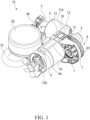
- an air compressor 10 according to a preferred embodiment of the present invention is received in an accommodation box 8.
- the air compressor 10 includes a body 1 configured to fix a motor 4, a cylinder 2 connected with the body 1, and a piston 5 driven by the motor 4 to move in the cylinder 2 reciprocately.
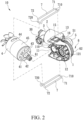
- the body 1 includes multiple positioning orifices which are a first positioning orifice 11 and a second positioning orifice 12, wherein a small gear 61 is received in the first positioning orifice 11 and is connected on an end of the motor 4, and a connection seat 41 of the motor 4 is accommodated in the first orifice 11.
- the second positioning orifice 12 is configured to receive a bearing 121.
- the motor 4 includes a magnetic coil 45 fitted thereon, made of metal material, and configured to conduct magnetism, thus enhancing operation efficiency of the motor 4.
- the cylinder 2 is one-piece connected on the body 1 and is in communication with an air storage holder 3, wherein the air storage holder 3 includes at least one tube 30 in which an air hose 31 and a pressure gauge 32 are received.
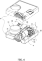
- a transmission mechanism 6 includes a large gear 62 having a counterweight block and configured to mesh with the small gear 61, wherein the large gear 62 is connected with a piston rod 51 of the piston 5 by using an eccentric crank, and the transmission mechanism 6 actuates the piston 5 to move in the cylinder 2 reciprocately so as to produce compressed airs.
- the fixing device of the motor of the air compressor comprises at least one retainer 7 configured to fix the body 1 and the motor 4, wherein a first end of the at least one retainer 7 is engaged on the body 1, and a second end of the at least one retainer 7 is engaged on a casing of the motor 4 so that the motor 4 is fixed on the body 1 without using any screws.
- the motor 4 further includes two dissipation holes 44 symmetrically formed on two sides of the casing thereof and configured to circulate airs and to dissipate heat from the motor 4.
- the motor 4 further includes multiple cavities 43 defined on an edge 42 thereof outside the connection seat 41, and the body 1 includes multiple posts 110 extending outside the first positioning orifice 11 and corresponding to the multiple cavities 43.
- the connection seat 41 of the edge 42 of the motor 4 is received in the first positioning orifice 11 of the body 1, wherein the first end of the at least one retainer 7 is engaged with at least one third positioning orifice 16 of the body 1, and the second end of the at least one retainer 7 is engaged on the two dissipation holes 44 of the casing of the motor 4 so that the motor 4 is fixed on the body 1 securely without using any screws.
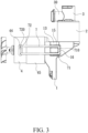
- the first end of the at least one retainer 7 is an open segment 71
- the second end of the at least one retainer 7 is a close segment 72
- the open segment 71 of the at least one retainer 7 has a first bent engagement portion 710
- the close segment 72 of the at least one retainer 7 has a second bent engagement portion 720.
- the at least one retainer 7 is received in the two receiving grooves 15 of the body 1, the first bent engagement portion 710 of the open segment 71 of the at least one retainer 7 is engaged with the two third positioning orifices 16 of the body 1, and the second bent engagement portion 720 of the close segment 72 of the at least one retainer 7 is engaged with the two dissipation holes 44 of the casing of the motor 4, such that the motor 4 is fixed on the body 1 without using any screws, and the at least one retainer 7 is accommodated in the two receiving grooves 15 to avoid a removal from the body 1, as shown in FIG. 3 .
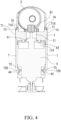
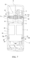
- the air compressor 10 is received in the accommodation box 8, and a retaining portion 81 of an inner wall of the accommodation box 8 has a trench 82 configured to limit the at least one retainer 7 between the motor 4 and the body 1 so as to avoid the removal of the at least one retainer 7 from the air compressor 10.
- the fixing device of the motor 4 of the air compressor 10 contains the multiple cavities 43 of the motor 4 configured to engage on the multiple posts 110 of the body 1, and the at least one retainer 7 is configured to fix the body 1 and the motor 4.
- the first end of the at least one retainer 7 is engaged with the body 1, and the second end of the at least one retainer 7 is engaged on the casing of the motor 4 so that the motor 4 is fixed on the body 1 securely without using any screws.
Landscapes
- Engineering & Computer Science (AREA)
- Mechanical Engineering (AREA)
- General Engineering & Computer Science (AREA)
- Power Engineering (AREA)
- Compressor (AREA)
- Compressors, Vaccum Pumps And Other Relevant Systems (AREA)
- Motor Or Generator Frames (AREA)
- Structures Of Non-Positive Displacement Pumps (AREA)
Claims (4)
- Motorgetriebener Luftkompressor mit einer Befestigungsvorrichtung für den Motor (4), wobei der motorgetriebene Luftkompressor (10) in einem Unterbringungskasten (8) aufgenommen ist und umfasst:einen Körper (1) mit mehreren Positionieröffnungen, die eine erste Positionieröffnung (11) und eine zweite Positionieröffnung (12) sind;einen Zylinder (2), der mit dem Körper (1) verbunden ist und mit einem Luftspeicherbehälter (3) in Verbindung steht;einen Motor (4), der an dem Körper (1) befestigt ist, wobei ein kleines Zahnrad (61) in der ersten Positionierungsöffnung (11) des Körpers (1) aufgenommen und mit einem Ende des Motors (4) verbunden ist, und ein Verbindungssitz (41) des Motors (4) in der ersten Öffnung (11) untergebracht ist;einen Übertragungsmechanismus (6), der einen Kolben (5) so betätigt, dass er sich in dem Zylinder (2) hin- und herbewegt, um Druckluft zu erzeugen, wobei mindestens ein Halter (7) so konfiguriert ist, dass er den Körper (1) und den Motor (4) fixiert, wobei ein erstes Ende des mindestens einen Halters (7) mit dem Körper (1) in Eingriff steht und ein zweites Ende des mindestens einen Halters (7) mit einem Gehäuse des Motors (4) in Eingriff steht, so dass der Motor (4) ohne Verwendung von Schrauben an dem Körper (1) fixiert ist,wobei der Motor (4) zwei Ableitungslöcher (44) aufweist, die symmetrisch auf zwei Seiten des Gehäuses ausgebildet sind,dadurch gekennzeichnet, dassdas erste Ende des mindestens einen Halters (7) ein offenes Segment (71) ist, und das zweite Ende des mindestens einen Halters (7) ein geschlossenes Segment (72) ist, wobei das offene Segment (71) des mindestens einen Halters (7) einen ersten gebogenen Eingriffsabschnitt (710) aufweist, und das geschlossene Segment (72) des mindestens einen Halters (7) einen zweiten gebogenen Eingriffsabschnitt (720) aufweist, und wobei, wenn der Übertragungsmechanismus (6) mit dem Körper (1) verbunden ist und der Zylinder (2) mit einem oberen Abschnitt des Körpers (1) gegenüber dem Übertragungsmechanismus (6) verbunden ist, ein erster Außenanschlag (13) und ein zweiter Außenanschlag (14) des Körpers (1) mit zwei Aufnahmenuten (15) und zwei dritten Positionieröffnungen (16), die alle an dem ersten Außenanschlag (13) und dem zweiten Außenanschlag (14) definiert sind, der mindestens eine Halter (7) in den beiden Aufnahmenuten (15) des Körpers (1) aufgenommen ist, der erste gebogene Eingriffsabschnitt (710) des offenen Segments (71) des mindestens einen Halters (7) mit den beiden dritten Positionierungsöffnungen (16) des Körpers (1) in Eingriff steht und der zweite gebogene Eingriffsabschnitt (720) des geschlossenen Segments (72) des mindestens einen Halters (7) mit den beiden Ableitungslöchern (44) des Gehäuses des Motors (4) in Eingriff steht.
- Motorgetriebener Luftkompressor (10) gemäß Anspruch 1, dadurch gekennzeichnet, dass das erste Ende des mindestens einen Halters (7) an dem Körper (1) eingreift und das zweite Ende des mindestens einen Halters (7) an den zwei Ableitungslöchern (44) des Gehäuses des Motors (4) eingreift, so dass der Motor (4) an dem Körper (1) ohne Verwendung irgendwelcher Schrauben befestigt ist.
- Motorgetriebener Luftkompressor (10) gemäß Anspruch 1, dadurch gekennzeichnet, dass der Motor (4) außerdem mehrere Hohlräume (43) aufweist, die an einem Rand (42) dessen außerhalb des Verbindungssitzes (41) definiert sind, und dass der Körper (1) mehrere Pfosten (110) aufweist, die sich außerhalb der ersten Positionierungsöffnung (11) erstrecken und den mehreren Hohlräumen (43) entsprechen; beim Befestigen des Motors (4) an dem Körper (1) die mehreren Hohlräume (43) des Randes (42) des Motors (4) in die mehreren Pfosten (110) des Körpers (1) eingreifen, um den Motor (4) zu befestigen.
- Motorgetriebener Luftkompressor (10) gemäß Anspruch 1, dadurch gekennzeichnet, dass der Luftkompressor (10) in dem Unterbringungskasten (8) aufgenommen ist und ein Halteabschnitt (81) einer Innenwand des Unterbringungskastens (8) einen Graben (82) aufweist, der so konfiguriert ist, dass er den mindestens einen Halter (7) zwischen dem Motor (4) und dem Körper (1) begrenzt, um ein Entfernen des mindestens einen Halters (7) von dem Luftkompressor (10) zu vermeiden.
Applications Claiming Priority (1)
| Application Number | Priority Date | Filing Date | Title |
|---|---|---|---|
| TW110118139A TWI784531B (zh) | 2021-05-19 | 2021-05-19 | 空氣壓縮機之馬達結合定位裝置 |
Publications (2)
| Publication Number | Publication Date |
|---|---|
| EP4092270A1 EP4092270A1 (de) | 2022-11-23 |
| EP4092270B1 true EP4092270B1 (de) | 2024-10-02 |
Family
ID=81603529
Family Applications (1)
| Application Number | Title | Priority Date | Filing Date |
|---|---|---|---|
| EP22172700.1A Active EP4092270B1 (de) | 2021-05-19 | 2022-05-11 | Befestigungsvorrichtung für den motor eines luftkompressors |
Country Status (7)
| Country | Link |
|---|---|
| US (1) | US11913440B2 (de) |
| EP (1) | EP4092270B1 (de) |
| JP (2) | JP3238305U (de) |
| KR (1) | KR102687025B1 (de) |
| CN (2) | CN115395703B (de) |
| DE (1) | DE202022102475U1 (de) |
| TW (1) | TWI784531B (de) |
Families Citing this family (2)
| Publication number | Priority date | Publication date | Assignee | Title |
|---|---|---|---|---|
| TWI784531B (zh) * | 2021-05-19 | 2022-11-21 | 周文三 | 空氣壓縮機之馬達結合定位裝置 |
| DE102024203323A1 (de) * | 2024-04-11 | 2025-10-16 | Continental Reifen Deutschland Gmbh | Pannenhilfesystem und Verfahren zum Montieren |
Family Cites Families (13)
| Publication number | Priority date | Publication date | Assignee | Title |
|---|---|---|---|---|
| US4306841A (en) * | 1980-01-30 | 1981-12-22 | Whirlpool Corporation | Pump mounting for an automatic washer |
| JP3204419B2 (ja) | 1992-10-21 | 2001-09-04 | 東陶機器株式会社 | トイレ装置 |
| KR0145382B1 (ko) | 1995-03-21 | 1998-08-17 | 김주용 | 플래쉬 이이피롬셀의 문턱전압 자동 검증회로 |
| US6095758A (en) | 1998-03-30 | 2000-08-01 | Chou; Wen-San | Structure for a compact air compressor |
| CN2530383Y (zh) * | 2002-01-14 | 2003-01-08 | 建准电机工业股份有限公司 | 马达的轴管构造 |
| US20060083631A1 (en) * | 2004-10-13 | 2006-04-20 | Walbro Engine Management, L.L.C. | Fuel pump assembly |
| TWI575159B (zh) * | 2014-05-26 | 2017-03-21 | 周文三 | 可攜式打氣機設備組 |
| TWI563172B (en) * | 2015-03-11 | 2016-12-21 | Wen-San Chou | Inflator having an enhanced cooling effect on a motor thereof |
| TWI589776B (zh) | 2015-03-11 | 2017-07-01 | 周文三 | 打氣機設備組結構 |
| TWI698581B (zh) * | 2018-12-14 | 2020-07-11 | 周文三 | 空氣壓縮機之馬達結合定位構造 |
| TWM587698U (zh) * | 2018-12-17 | 2019-12-11 | 周文三 | 空壓機之馬達結合定位構造 |
| TWI691649B (zh) | 2018-12-17 | 2020-04-21 | 周文三 | 空壓機之馬達結合定位構造 |
| TWI784531B (zh) | 2021-05-19 | 2022-11-21 | 周文三 | 空氣壓縮機之馬達結合定位裝置 |
-
2021
- 2021-05-19 TW TW110118139A patent/TWI784531B/zh active
-
2022
- 2022-05-03 KR KR1020220054632A patent/KR102687025B1/ko active Active
- 2022-05-05 DE DE202022102475.8U patent/DE202022102475U1/de active Active
- 2022-05-08 US US17/739,141 patent/US11913440B2/en active Active
- 2022-05-09 CN CN202210500421.5A patent/CN115395703B/zh active Active
- 2022-05-09 CN CN202221099645.1U patent/CN217883022U/zh not_active Withdrawn - After Issue
- 2022-05-11 EP EP22172700.1A patent/EP4092270B1/de active Active
- 2022-05-18 JP JP2022001617U patent/JP3238305U/ja active Active
- 2022-05-18 JP JP2022081228A patent/JP7474282B2/ja active Active
Also Published As
| Publication number | Publication date |
|---|---|
| KR102687025B1 (ko) | 2024-07-19 |
| CN115395703B (zh) | 2026-02-06 |
| TWI784531B (zh) | 2022-11-21 |
| CN217883022U (zh) | 2022-11-22 |
| JP3238305U (ja) | 2022-07-14 |
| US11913440B2 (en) | 2024-02-27 |
| US20220372970A1 (en) | 2022-11-24 |
| EP4092270A1 (de) | 2022-11-23 |
| DE202022102475U1 (de) | 2022-05-18 |
| KR20220156750A (ko) | 2022-11-28 |
| TW202246652A (zh) | 2022-12-01 |
| JP2022179409A (ja) | 2022-12-02 |
| JP7474282B2 (ja) | 2024-04-24 |
| CN115395703A (zh) | 2022-11-25 |
Similar Documents
| Publication | Publication Date | Title |
|---|---|---|
| EP3667084B1 (de) | Verbindungsstruktur für einen motor eines luftkompressors | |
| EP4092270B1 (de) | Befestigungsvorrichtung für den motor eines luftkompressors | |
| EP4092269A1 (de) | Luftkompressor | |
| EP3670911B1 (de) | Positionierstruktur eines motors eines luftverdichters | |
| JP4021848B2 (ja) | 往復動式圧縮機の摩耗防止構造 | |
| EP3128173B1 (de) | Linearverdichter | |
| US10641261B2 (en) | Pump with motor | |
| EP3608540B1 (de) | Befestigungsstruktur für lager eines luftverdichters | |
| EP4095380B1 (de) | Luftkompressor | |
| EP4095379B1 (de) | Befestigungsvorrichtung für den motor eines luftkompressors | |
| JP2004183645A (ja) | 往復動式圧縮機の潤滑装置 | |
| US7540723B2 (en) | Reciprocating compressor | |
| US20140377096A1 (en) | Motor-driven compressor | |
| US11204023B2 (en) | Positioning structure of motor of air compressor | |
| EP1693568A1 (de) | Luftkompressor mit stabilem Zustand | |
| KR101202902B1 (ko) | 리니어 압축기의 본체프레임 | |
| KR100459481B1 (ko) | 왕복동식 압축기의 가스 압축구조 | |
| KR200170971Y1 (ko) | 압축기의 코일 어스단자 조립장치 | |
| KR100783410B1 (ko) | 왕복동식 압축기의 토출밸브 조립체 | |
| KR20030047427A (ko) | 왕복동식 압축기의 모터 에어 갭 측정구조 | |
| KR20010109671A (ko) | 리니어 압축기의 유동저항 저감구조 |
Legal Events
| Date | Code | Title | Description |
|---|---|---|---|
| PUAI | Public reference made under article 153(3) epc to a published international application that has entered the european phase |
Free format text: ORIGINAL CODE: 0009012 |
|
| STAA | Information on the status of an ep patent application or granted ep patent |
Free format text: STATUS: REQUEST FOR EXAMINATION WAS MADE |
|
| 17P | Request for examination filed |
Effective date: 20220906 |
|
| AK | Designated contracting states |
Kind code of ref document: A1 Designated state(s): AL AT BE BG CH CY CZ DE DK EE ES FI FR GB GR HR HU IE IS IT LI LT LU LV MC MK MT NL NO PL PT RO RS SE SI SK SM TR |
|
| STAA | Information on the status of an ep patent application or granted ep patent |
Free format text: STATUS: EXAMINATION IS IN PROGRESS |
|
| 17Q | First examination report despatched |
Effective date: 20240213 |
|
| GRAP | Despatch of communication of intention to grant a patent |
Free format text: ORIGINAL CODE: EPIDOSNIGR1 |
|
| STAA | Information on the status of an ep patent application or granted ep patent |
Free format text: STATUS: GRANT OF PATENT IS INTENDED |
|
| INTG | Intention to grant announced |
Effective date: 20240711 |
|
| GRAS | Grant fee paid |
Free format text: ORIGINAL CODE: EPIDOSNIGR3 |
|
| GRAA | (expected) grant |
Free format text: ORIGINAL CODE: 0009210 |
|
| STAA | Information on the status of an ep patent application or granted ep patent |
Free format text: STATUS: THE PATENT HAS BEEN GRANTED |
|
| AK | Designated contracting states |
Kind code of ref document: B1 Designated state(s): AL AT BE BG CH CY CZ DE DK EE ES FI FR GB GR HR HU IE IS IT LI LT LU LV MC MK MT NL NO PL PT RO RS SE SI SK SM TR |
|
| REG | Reference to a national code |
Ref country code: GB Ref legal event code: FG4D |
|
| REG | Reference to a national code |
Ref country code: CH Ref legal event code: EP |
|
| REG | Reference to a national code |
Ref country code: IE Ref legal event code: FG4D |
|
| REG | Reference to a national code |
Ref country code: DE Ref legal event code: R096 Ref document number: 602022006456 Country of ref document: DE |
|
| REG | Reference to a national code |
Ref country code: LT Ref legal event code: MG9D |
|
| REG | Reference to a national code |
Ref country code: NL Ref legal event code: MP Effective date: 20241002 |
|
| REG | Reference to a national code |
Ref country code: AT Ref legal event code: MK05 Ref document number: 1728690 Country of ref document: AT Kind code of ref document: T Effective date: 20241002 |
|
| PG25 | Lapsed in a contracting state [announced via postgrant information from national office to epo] |
Ref country code: NL Free format text: LAPSE BECAUSE OF FAILURE TO SUBMIT A TRANSLATION OF THE DESCRIPTION OR TO PAY THE FEE WITHIN THE PRESCRIBED TIME-LIMIT Effective date: 20241002 |
|
| PG25 | Lapsed in a contracting state [announced via postgrant information from national office to epo] |
Ref country code: NL Free format text: LAPSE BECAUSE OF FAILURE TO SUBMIT A TRANSLATION OF THE DESCRIPTION OR TO PAY THE FEE WITHIN THE PRESCRIBED TIME-LIMIT Effective date: 20241002 |
|
| PG25 | Lapsed in a contracting state [announced via postgrant information from national office to epo] |
Ref country code: HR Free format text: LAPSE BECAUSE OF FAILURE TO SUBMIT A TRANSLATION OF THE DESCRIPTION OR TO PAY THE FEE WITHIN THE PRESCRIBED TIME-LIMIT Effective date: 20241002 Ref country code: PT Free format text: LAPSE BECAUSE OF FAILURE TO SUBMIT A TRANSLATION OF THE DESCRIPTION OR TO PAY THE FEE WITHIN THE PRESCRIBED TIME-LIMIT Effective date: 20250203 Ref country code: IS Free format text: LAPSE BECAUSE OF FAILURE TO SUBMIT A TRANSLATION OF THE DESCRIPTION OR TO PAY THE FEE WITHIN THE PRESCRIBED TIME-LIMIT Effective date: 20250202 |
|
| PG25 | Lapsed in a contracting state [announced via postgrant information from national office to epo] |
Ref country code: FI Free format text: LAPSE BECAUSE OF FAILURE TO SUBMIT A TRANSLATION OF THE DESCRIPTION OR TO PAY THE FEE WITHIN THE PRESCRIBED TIME-LIMIT Effective date: 20241002 |
|
| PG25 | Lapsed in a contracting state [announced via postgrant information from national office to epo] |
Ref country code: BG Free format text: LAPSE BECAUSE OF FAILURE TO SUBMIT A TRANSLATION OF THE DESCRIPTION OR TO PAY THE FEE WITHIN THE PRESCRIBED TIME-LIMIT Effective date: 20241002 |
|
| PG25 | Lapsed in a contracting state [announced via postgrant information from national office to epo] |
Ref country code: ES Free format text: LAPSE BECAUSE OF FAILURE TO SUBMIT A TRANSLATION OF THE DESCRIPTION OR TO PAY THE FEE WITHIN THE PRESCRIBED TIME-LIMIT Effective date: 20241002 |
|
| PG25 | Lapsed in a contracting state [announced via postgrant information from national office to epo] |
Ref country code: NO Free format text: LAPSE BECAUSE OF FAILURE TO SUBMIT A TRANSLATION OF THE DESCRIPTION OR TO PAY THE FEE WITHIN THE PRESCRIBED TIME-LIMIT Effective date: 20250102 |
|
| PG25 | Lapsed in a contracting state [announced via postgrant information from national office to epo] |
Ref country code: AT Free format text: LAPSE BECAUSE OF FAILURE TO SUBMIT A TRANSLATION OF THE DESCRIPTION OR TO PAY THE FEE WITHIN THE PRESCRIBED TIME-LIMIT Effective date: 20241002 Ref country code: LV Free format text: LAPSE BECAUSE OF FAILURE TO SUBMIT A TRANSLATION OF THE DESCRIPTION OR TO PAY THE FEE WITHIN THE PRESCRIBED TIME-LIMIT Effective date: 20241002 Ref country code: GR Free format text: LAPSE BECAUSE OF FAILURE TO SUBMIT A TRANSLATION OF THE DESCRIPTION OR TO PAY THE FEE WITHIN THE PRESCRIBED TIME-LIMIT Effective date: 20250103 |
|
| PG25 | Lapsed in a contracting state [announced via postgrant information from national office to epo] |
Ref country code: PL Free format text: LAPSE BECAUSE OF FAILURE TO SUBMIT A TRANSLATION OF THE DESCRIPTION OR TO PAY THE FEE WITHIN THE PRESCRIBED TIME-LIMIT Effective date: 20241002 Ref country code: CZ Free format text: LAPSE BECAUSE OF FAILURE TO SUBMIT A TRANSLATION OF THE DESCRIPTION OR TO PAY THE FEE WITHIN THE PRESCRIBED TIME-LIMIT Effective date: 20241002 |
|
| PG25 | Lapsed in a contracting state [announced via postgrant information from national office to epo] |
Ref country code: RS Free format text: LAPSE BECAUSE OF FAILURE TO SUBMIT A TRANSLATION OF THE DESCRIPTION OR TO PAY THE FEE WITHIN THE PRESCRIBED TIME-LIMIT Effective date: 20250102 |
|
| PG25 | Lapsed in a contracting state [announced via postgrant information from national office to epo] |
Ref country code: SM Free format text: LAPSE BECAUSE OF FAILURE TO SUBMIT A TRANSLATION OF THE DESCRIPTION OR TO PAY THE FEE WITHIN THE PRESCRIBED TIME-LIMIT Effective date: 20241002 |
|
| REG | Reference to a national code |
Ref country code: DE Ref legal event code: R097 Ref document number: 602022006456 Country of ref document: DE |
|
| PGFP | Annual fee paid to national office [announced via postgrant information from national office to epo] |
Ref country code: DE Payment date: 20250403 Year of fee payment: 4 |
|
| PG25 | Lapsed in a contracting state [announced via postgrant information from national office to epo] |
Ref country code: DK Free format text: LAPSE BECAUSE OF FAILURE TO SUBMIT A TRANSLATION OF THE DESCRIPTION OR TO PAY THE FEE WITHIN THE PRESCRIBED TIME-LIMIT Effective date: 20241002 |
|
| PG25 | Lapsed in a contracting state [announced via postgrant information from national office to epo] |
Ref country code: EE Free format text: LAPSE BECAUSE OF FAILURE TO SUBMIT A TRANSLATION OF THE DESCRIPTION OR TO PAY THE FEE WITHIN THE PRESCRIBED TIME-LIMIT Effective date: 20241002 |
|
| PG25 | Lapsed in a contracting state [announced via postgrant information from national office to epo] |
Ref country code: RO Free format text: LAPSE BECAUSE OF FAILURE TO SUBMIT A TRANSLATION OF THE DESCRIPTION OR TO PAY THE FEE WITHIN THE PRESCRIBED TIME-LIMIT Effective date: 20241002 |
|
| PG25 | Lapsed in a contracting state [announced via postgrant information from national office to epo] |
Ref country code: SK Free format text: LAPSE BECAUSE OF FAILURE TO SUBMIT A TRANSLATION OF THE DESCRIPTION OR TO PAY THE FEE WITHIN THE PRESCRIBED TIME-LIMIT Effective date: 20241002 |
|
| PG25 | Lapsed in a contracting state [announced via postgrant information from national office to epo] |
Ref country code: IT Free format text: LAPSE BECAUSE OF FAILURE TO SUBMIT A TRANSLATION OF THE DESCRIPTION OR TO PAY THE FEE WITHIN THE PRESCRIBED TIME-LIMIT Effective date: 20241002 |
|
| PLBE | No opposition filed within time limit |
Free format text: ORIGINAL CODE: 0009261 |
|
| STAA | Information on the status of an ep patent application or granted ep patent |
Free format text: STATUS: NO OPPOSITION FILED WITHIN TIME LIMIT |
|
| PG25 | Lapsed in a contracting state [announced via postgrant information from national office to epo] |
Ref country code: SE Free format text: LAPSE BECAUSE OF FAILURE TO SUBMIT A TRANSLATION OF THE DESCRIPTION OR TO PAY THE FEE WITHIN THE PRESCRIBED TIME-LIMIT Effective date: 20241002 |
|
| 26N | No opposition filed |
Effective date: 20250703 |
|
| REG | Reference to a national code |
Ref country code: CH Ref legal event code: H13 Free format text: ST27 STATUS EVENT CODE: U-0-0-H10-H13 (AS PROVIDED BY THE NATIONAL OFFICE) Effective date: 20251223 |
|
| PG25 | Lapsed in a contracting state [announced via postgrant information from national office to epo] |
Ref country code: LU Free format text: LAPSE BECAUSE OF NON-PAYMENT OF DUE FEES Effective date: 20250511 |
|
| PG25 | Lapsed in a contracting state [announced via postgrant information from national office to epo] |
Ref country code: CH Free format text: LAPSE BECAUSE OF NON-PAYMENT OF DUE FEES Effective date: 20250531 |
|
| REG | Reference to a national code |
Ref country code: BE Ref legal event code: MM Effective date: 20250531 |
|
| PG25 | Lapsed in a contracting state [announced via postgrant information from national office to epo] |
Ref country code: MC Free format text: LAPSE BECAUSE OF FAILURE TO SUBMIT A TRANSLATION OF THE DESCRIPTION OR TO PAY THE FEE WITHIN THE PRESCRIBED TIME-LIMIT Effective date: 20241002 |