EP3608540B1 - Befestigungsstruktur für lager eines luftverdichters - Google Patents
Befestigungsstruktur für lager eines luftverdichters Download PDFInfo
- Publication number
- EP3608540B1 EP3608540B1 EP19190880.5A EP19190880A EP3608540B1 EP 3608540 B1 EP3608540 B1 EP 3608540B1 EP 19190880 A EP19190880 A EP 19190880A EP 3608540 B1 EP3608540 B1 EP 3608540B1
- Authority
- EP
- European Patent Office
- Prior art keywords
- bearing
- ring
- air compressor
- transmission mechanism
- positioning orifice
- Prior art date
- Legal status (The legal status is an assumption and is not a legal conclusion. Google has not performed a legal analysis and makes no representation as to the accuracy of the status listed.)
- Active
Links
- 230000005540 biological transmission Effects 0.000 claims description 23
- 230000002093 peripheral effect Effects 0.000 claims description 12
- 230000000717 retained effect Effects 0.000 claims description 8
- 238000004663 powder metallurgy Methods 0.000 claims description 2
- 238000007599 discharging Methods 0.000 description 1
- 239000000463 material Substances 0.000 description 1
Images


Classifications
-
- F—MECHANICAL ENGINEERING; LIGHTING; HEATING; WEAPONS; BLASTING
- F04—POSITIVE - DISPLACEMENT MACHINES FOR LIQUIDS; PUMPS FOR LIQUIDS OR ELASTIC FLUIDS
- F04B—POSITIVE-DISPLACEMENT MACHINES FOR LIQUIDS; PUMPS
- F04B39/00—Component parts, details, or accessories, of pumps or pumping systems specially adapted for elastic fluids, not otherwise provided for in, or of interest apart from, groups F04B25/00 - F04B37/00
-
- F—MECHANICAL ENGINEERING; LIGHTING; HEATING; WEAPONS; BLASTING
- F04—POSITIVE - DISPLACEMENT MACHINES FOR LIQUIDS; PUMPS FOR LIQUIDS OR ELASTIC FLUIDS
- F04B—POSITIVE-DISPLACEMENT MACHINES FOR LIQUIDS; PUMPS
- F04B35/00—Piston pumps specially adapted for elastic fluids and characterised by the driving means to their working members, or by combination with, or adaptation to, specific driving engines or motors, not otherwise provided for
- F04B35/01—Piston pumps specially adapted for elastic fluids and characterised by the driving means to their working members, or by combination with, or adaptation to, specific driving engines or motors, not otherwise provided for the means being mechanical
-
- F—MECHANICAL ENGINEERING; LIGHTING; HEATING; WEAPONS; BLASTING
- F04—POSITIVE - DISPLACEMENT MACHINES FOR LIQUIDS; PUMPS FOR LIQUIDS OR ELASTIC FLUIDS
- F04B—POSITIVE-DISPLACEMENT MACHINES FOR LIQUIDS; PUMPS
- F04B35/00—Piston pumps specially adapted for elastic fluids and characterised by the driving means to their working members, or by combination with, or adaptation to, specific driving engines or motors, not otherwise provided for
- F04B35/04—Piston pumps specially adapted for elastic fluids and characterised by the driving means to their working members, or by combination with, or adaptation to, specific driving engines or motors, not otherwise provided for the means being electric
-
- F—MECHANICAL ENGINEERING; LIGHTING; HEATING; WEAPONS; BLASTING
- F04—POSITIVE - DISPLACEMENT MACHINES FOR LIQUIDS; PUMPS FOR LIQUIDS OR ELASTIC FLUIDS
- F04B—POSITIVE-DISPLACEMENT MACHINES FOR LIQUIDS; PUMPS
- F04B39/00—Component parts, details, or accessories, of pumps or pumping systems specially adapted for elastic fluids, not otherwise provided for in, or of interest apart from, groups F04B25/00 - F04B37/00
- F04B39/12—Casings; Cylinders; Cylinder heads; Fluid connections
-
- F—MECHANICAL ENGINEERING; LIGHTING; HEATING; WEAPONS; BLASTING
- F04—POSITIVE - DISPLACEMENT MACHINES FOR LIQUIDS; PUMPS FOR LIQUIDS OR ELASTIC FLUIDS
- F04B—POSITIVE-DISPLACEMENT MACHINES FOR LIQUIDS; PUMPS
- F04B39/00—Component parts, details, or accessories, of pumps or pumping systems specially adapted for elastic fluids, not otherwise provided for in, or of interest apart from, groups F04B25/00 - F04B37/00
- F04B39/14—Provisions for readily assembling or disassembling
-
- F—MECHANICAL ENGINEERING; LIGHTING; HEATING; WEAPONS; BLASTING
- F16—ENGINEERING ELEMENTS AND UNITS; GENERAL MEASURES FOR PRODUCING AND MAINTAINING EFFECTIVE FUNCTIONING OF MACHINES OR INSTALLATIONS; THERMAL INSULATION IN GENERAL
- F16C—SHAFTS; FLEXIBLE SHAFTS; ELEMENTS OR CRANKSHAFT MECHANISMS; ROTARY BODIES OTHER THAN GEARING ELEMENTS; BEARINGS
- F16C19/00—Bearings with rolling contact, for exclusively rotary movement
- F16C19/02—Bearings with rolling contact, for exclusively rotary movement with bearing balls essentially of the same size in one or more circular rows
- F16C19/04—Bearings with rolling contact, for exclusively rotary movement with bearing balls essentially of the same size in one or more circular rows for radial load mainly
- F16C19/06—Bearings with rolling contact, for exclusively rotary movement with bearing balls essentially of the same size in one or more circular rows for radial load mainly with a single row or balls
-
- F—MECHANICAL ENGINEERING; LIGHTING; HEATING; WEAPONS; BLASTING
- F05—INDEXING SCHEMES RELATING TO ENGINES OR PUMPS IN VARIOUS SUBCLASSES OF CLASSES F01-F04
- F05B—INDEXING SCHEME RELATING TO WIND, SPRING, WEIGHT, INERTIA OR LIKE MOTORS, TO MACHINES OR ENGINES FOR LIQUIDS COVERED BY SUBCLASSES F03B, F03D AND F03G
- F05B2210/00—Working fluid
- F05B2210/16—Air or water being indistinctly used as working fluid, i.e. the machine can work equally with air or water without any modification
-
- F—MECHANICAL ENGINEERING; LIGHTING; HEATING; WEAPONS; BLASTING
- F05—INDEXING SCHEMES RELATING TO ENGINES OR PUMPS IN VARIOUS SUBCLASSES OF CLASSES F01-F04
- F05B—INDEXING SCHEME RELATING TO WIND, SPRING, WEIGHT, INERTIA OR LIKE MOTORS, TO MACHINES OR ENGINES FOR LIQUIDS COVERED BY SUBCLASSES F03B, F03D AND F03G
- F05B2240/00—Components
- F05B2240/50—Bearings
-
- F—MECHANICAL ENGINEERING; LIGHTING; HEATING; WEAPONS; BLASTING
- F16—ENGINEERING ELEMENTS AND UNITS; GENERAL MEASURES FOR PRODUCING AND MAINTAINING EFFECTIVE FUNCTIONING OF MACHINES OR INSTALLATIONS; THERMAL INSULATION IN GENERAL
- F16C—SHAFTS; FLEXIBLE SHAFTS; ELEMENTS OR CRANKSHAFT MECHANISMS; ROTARY BODIES OTHER THAN GEARING ELEMENTS; BEARINGS
- F16C2360/00—Engines or pumps
- F16C2360/42—Pumps with cylinders or pistons
Definitions
- the present invention relates to a bearing fixing structure of an air compressor which avoids an idle rotation of the bearing in the base or a removal of the bearing from the second positioning orifice.
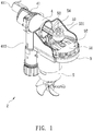
- a conventional air compressor 1 for a vehicle contains: a base 11, a cylinder 12 connected on the base 11, a motor fixed on the base, and a piston driven by the motor to move in the cylinder 12 reciprocatingly, thus drawing, compressing, pressurizing, and discharging air out of the cylinder.
- the motor is driven by a gear mechanism and a crank mechanism so as to actuate the piston to move.
- the gear mechanism includes a pinion fitted on a central shaft of the motor and a driven gear meshing with the pinion, a counterweight block of the crank mechanism is connected on the driven gear, and a connection post is rotatably connected with the piston.
- the base 11 includes an orifice 110 configured to accommodate a bearing 111 which is circular, and the connection post is eccentric with a shaft.
- the base 11 is made of plastic, so it is easy to be softened.
- the piston pulls the bearing 111 each other to cause deformation, and the piston offset greatly to damage the orifice 110, thus reducing a service life of the piston and the bearing 111.
- the present invention has arisen to mitigate and/or obviate the afore-described disadvantages.
- the primary aspect of the present invention is to provide a structure for fixing a bearing of an air compressor which avoids an idle rotation of the bearing in the base or a removal of the bearing from the second positioning orifice.
- Another aspect of the present invention is to provide a structure of fixing a bearing of an air compressor in which the piston operates in the cylinder smoothly, thus prolonging a service life of the air compressor.
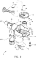
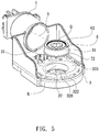
- the air compressor 2 comprises: a base 3, a cylinder 4 connected on the base 3, a motor 5 and a transmission mechanism 51 which are connected with the base 3.
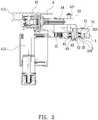
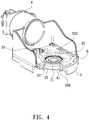
- the base 3 includes multiple positioning orifices (i.e., a first positioning orifice 31 and a second positioning orifice 32), wherein the first positioning orifice 31 accommodates a pinion 50 on a core end of the motor 5, the second positioning orifice 32 accommodates the bearing 6, wherein the bearing 6 includes a first ring 61, a second ring 62, and multiple balls 63 defined between the first ring 61 and the second ring 62, wherein the second positioning orifice 32 includes a shoulder 320 formed on a bottom thereof to avoid a removal of the bearing 6 from the second positioning orifice 32, and the second positioning orifice 32 includes a non-circular surrounding face 323 formed around a top thereof so that the bearing 6 is replaced onto the base 3, a central axis A of the cylinder 4 is perpendicular to a longitudinal axis B extending from a center of the second positioning orifice 32 so as to produce an intersection point Q, as shown in FIG.
- a piston 54 of the cylinder 4 operates normally instead of eccentrically.
- the non-circular surrounding face 323 facilitates a removal of the bearing 6 from the central axis of the cylinder 4 so that the central axis A is not perpendicular to and is intersected with the longitudinal axis B so that the piston 54 of the cylinder 4 operates eccentrically, thus not producing the intersection point Q.
- the cylinder 4 is integrally connected on the base 3, and the cylinder 4 includes an air storage chamber 41 communicating therewith, wherein the air storage chamber 41 has an air outflow pipe 411 configured to output air, and the air storage chamber 41 has a pressure gauge 412.
- the transmission mechanism 51 actuates the piston 54 to move in the cylinder 4 reciprocatingly so as to produce compressed air, wherein the transmission mechanism 51 is a gear integrally formed in a powder metallurgy manner and meshing with the pinion 50, wherein the transmission mechanism 51 includes a threaded hole 510 defined on a center thereof and a connection post 53 beside the threaded hole 510, wherein the connection post 53 has a notch 530 defined around a distal end thereof away from the threaded hole 510.
- the piston 54 is rotatably connected with the connection post 53 of the transmission mechanism 51, a locking disc 531 is retained with the notch 530 of the connection post 53 to avoid a removal of the piston 54 when the transmission mechanism 51 operates.
- the piston 54 is accommodated into the cylinder 4, the threaded hole 510 of the transmission mechanism 51 corresponds to the second ring 62 of the bearing 6 in the second positioning orifice 32 of the base 3, and a screw bolt 52 is inserted through the second ring 62 of the bearing 6 from the base 3 to screw with the threaded hole 510.
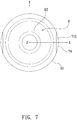
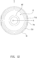
- the first ring 61 of the bearing 6 is non-circular, and a shape of the second positioning orifice 32 of the base 3 corresponds to the first ring 61 so as to avoid an idle rotation of the bearing 6 in the second positioning orifice 32 of the base 3 or a removal of the bearing 6 from the second positioning orifice 32.
- the first ring 61 of the bearing 6 has a peripheral recess 71 retained with a rib 321 of the second positioning orifice 32, such that the first ring 61 of the bearing 6 is locked, the bearing 6 does not remove when the transmission mechanism 51 operates, and the piston 54 operates in the cylinder 4 smoothly, thus prolonging a service life of the air compressor 2.
- the ring 61 of the bearing 6 has a protrusion 72 retained with a trench 322 of the second positioning orifice 32 of the base 3, such that the first ring 61 of the bearing 6 is locked, the bearing 6 does not remove when the transmission mechanism 51 operates, and the piston 54 operates in the cylinder 4 smoothly, thus prolonging the service life of the air compressor 2.
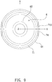
- the first ring 61 of the bearing 6 has at least one tangent plane 73 formed on an X axis of a three-dimensional space.
- the first ring 61 of the bearing 6 has a partial tangent plane 74 formed on an X axis of a three-dimensional space., i.e., the first ring 61 of the bearing 6 has at least one platform 741 formed on the X axis so that the bearing 6 does not rotate idly in or does not remove from the second positioning orifice 3, when the transmission mechanism 51 operates.
- the first ring 61 of the bearing 6 has the peripheral recess 71 retained with the rib 321, the partial tangent plane 74 and the at least one platform 741 which are formed on the X axis of a three-dimensional space.
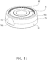
- the first ring 61 of the bearing 6 has a peripheral face 75 and a beveled face 751 extending from the peripheral face 75, wherein a diameter of the beveled face 751 is less than the peripheral face 75 so that the bearing 6 does not remove from the second positioning orifice 32 of the base 3, when the transmission mechanism 51 operates.
- the first ring 61 of the bearing 6 has the peripheral face 75, the beveled face 751, the partial tangent plane 74 and the at least one platform 741 which are formed on the X axis of the three-dimensional space.
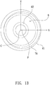
- the first ring 61 of the bearing 6 has a groove 76, a central axis P of which is not identical to a central axis C of the bearing 6, i.e., the first ring 61 is not concentric with the bearing 6.
- the screw bolt 53 of the transmission mechanism 51 is rotatably with the bearing 6, the first ring 61 of bearing 6 is non-circular, and the shape of the second positioning orifice 32 of the base 3 corresponds to the first ring 61 so as to avoid an idle rotation of the bearing 6 in the second positioning orifice 32 of the base 3 or a removal of the bearing 6 from the second positioning orifice 32.
- the piston 54 operates in the cylinder 4 smoothly, thus prolonging the service life of the air compressor 2.
Landscapes
- Engineering & Computer Science (AREA)
- General Engineering & Computer Science (AREA)
- Mechanical Engineering (AREA)
- Compressor (AREA)
- Compressors, Vaccum Pumps And Other Relevant Systems (AREA)
- Mounting Of Bearings Or Others (AREA)
- Rolling Contact Bearings (AREA)
Claims (13)
- Luftkompressor mit einem Lager (6), das einen ersten Ring (61) aufweist, wobei der Luftkompressor Folgendes umfasst:eine Basis (3), die mehrere Positionieröffnungen (31, 32) aufweist, wobei die mehreren Positionieröffnungen (31, 32) eine erste Positionieröffnung (31) und eine zweite Positionieröffnung (32) sind, wobei die zweite Positionieröffnung (32) das Lager (6) aufnimmt,einen Zylinder (4), der integral mit der Basis (3) verbunden ist und eine Luftspeicherkammer (41) aufweist, die mit dem Zylinder (4) in Verbindung steht, und einen Getriebemechanismus (51), der einen Kolben (54) betätigt, um sich in dem Zylinder (4) hin- und herzubewegen, um Druckluft zu erzeugen,wobei das Lager (6) ferner einen zweiten Ring (62) und mehrere Kugeln (63) aufweist, die zwischen dem ersten Ring (61) und dem zweiten Ring (62) definiert sind, unddadurch gekennzeichnet, dassder erste Ring (61) des Lagers (6) nicht kreisförmig ist und eine Form der zweiten Positionieröffnung (32) der Basis (3) dem ersten Ring (61) entspricht, wobei die zweite Positionieröffnung (32) ferner eine Schulter (320) aufweist, die an einem unteren Teil davon ausgebildet ist, um eine Leerlaufdrehung des Lagers (6) in der zweiten Positionieröffnung (32) der Basis (3) oder ein Entfernen des Lagers (6) von der zweiten Positionieröffnung (32) zu vermeiden.
- Luftkompressor nach Anspruch 1, bei welchem die erste Positionieröffnung (31) ein Ritzel (50) an einem Kernende des Motors (5) aufnimmt, wobei die zweite Positionieröffnung (32) eine nicht kreisförmige Umgebungsfläche (323) aufweist, die um ein Oberteil davon ausgebildet ist, sodass das Lager (6) wieder auf die Basis (3) hingelegt wird, wobei eine Mittelachse (A) des Zylinders (4) senkrecht zu einer Längsachse (B) ist, die sich von einer Mitte der zweiten Positionieröffnung (32) erstreckt, um einen Schnittpunkt (Q) zu erzeugen, währenddessen ein Kolben (54) des Zylinders (4) normal arbeitet, wobei die nicht kreisförmige Umgebungsfläche (323) ein Entfernen des Lagers (6) von der Mittelachse des Zylinders (4) erleichtert, sodass die Mittelachse (A) nicht senkrecht zu der Längsachse (B) ist und sich mit dieser überschneidet, sodass der Kolben (54) des Zylinders (4) exzentrisch arbeitet, wodurch kein Schnittpunkt (Q) erzeugt wird.
- Luftkompressor nach Anspruch 1, bei welchem der Getriebemechanismus (51) eine Gewindebohrung (510), die auf seiner Mitte definiert ist, und eine Verbindungsstange (53) neben der Gewindebohrung (510) aufweist, wobei die Gewindebohrung (510) des Getriebemechanismus (51) dem zweiten Ring (62) des Lagers (6) in der zweiten Positionieröffnung (32) der Basis (3) entspricht, ein Schraubenbolzen (52) durch den zweiten Ring (62) des Lagers (6) von der Basis (3) eingesetzt wird, um sich mit der Gewindebohrung (510) zu verschrauben, und der Kolben (54) drehbar mit der Verbindungsstange (53) des Getriebemechanismus (51) verbunden ist.
- Luftkompressor nach Anspruch 3, bei welchem der Getriebemechanismus (51) ein Zahnrad ist, das in einer pulvermetallurgischen Art integral ausgebildet ist und mit dem Ritzel (50) kämmt.
- Luftkompressor nach Anspruch 2, bei welchem der erste Ring (61) des Lagers (6) eine Umfangsaussparung (71) aufweist, die mit einer Rippe (321) der zweiten Positionieröffnung (32) gehalten wird, sodass der erste Ring (61) des Lagers (6) verriegelt ist, wobei das Lager (6) nicht entfernt wird, wenn der Getriebemechanismus (51) arbeitet.
- Luftkompressor nach Anspruch 2, bei welchem der erste Ring (61) des Lagers (6) einen Vorsprung (72) aufweist, der mit einer Vertiefung (322) der zweiten Positionieröffnung (32) der Basis (3) gehalten wird, sodass der erste Ring (61) des Lagers (6) verriegelt ist, wobei das Lager (6) nicht entfernt wird, wenn der Getriebemechanismus (51) arbeitet.
- Luftkompressor nach Anspruch 2, bei welchem der erste Ring (61) des Lagers (6) mindestens eine Tangentialebene (73) aufweist, die auf einer X-Achse ausgebildet ist.
- Luftkompressor nach Anspruch 5, bei welchem der erste Ring (61) des Lagers (6) eine partielle Tangentialebene (74) aufweist, die auf einer X-Achse ausgebildet ist, wobei der erste Ring (61) des Lagers (6) mindestens eine Plattform (741) aufweist, die auf der X-Achse ausgebildet ist, sodass sich das Lager (6) nicht im Leerlauf in der zweiten Positionieröffnung (3) dreht oder nicht von dieser entfernt wird, wenn der Getriebemechanismus (51) arbeitet.
- Luftkompressor nach Anspruch 8, bei welchem der erste Ring (61) des Lagers (6) die Umfangsaussparung (71), die mit der Rippe (321) gehalten wird, und die partielle Tangentialebene (74) und die mindestens eine Plattform (741) aufweist, die auf der X-Achse ausgebildet sind.
- Luftkompressor nach Anspruch 8, bei welchem der erste Ring (61) des Lagers (6) eine Umfangsfläche (75) und eine abgeschrägte Fläche (751) aufweist, die sich von der Umfangsfläche (75) erstreckt, wobei ein Durchmesser der abgeschrägten Fläche (751) kleiner als die Umfangsfläche (75) ist, sodass das Lager (6) nicht von der zweiten Positionieröffnung (32) der Basis (3) entfernt wird, wenn der Getriebemechanismus (51) arbeitet.
- Luftkompressor nach Anspruch 10, bei welchem der erste Ring (61) des Lagers (6) die Umfangsfläche (75), die abgeschrägte Fläche (751), die partielle Tangentialebene (74) und die mindestens eine Plattform (741) aufweist, die auf der X-Achse ausgebildet sind.
- Luftkompressor nach Anspruch 5, bei welchem der erste Ring (61) des Lagers (6) eine Nut (76) aufweist, deren Mittelachse (P) nicht mit einer Mittelachse (C) des Lagers (6) identisch ist, und der erste Ring (61) nicht konzentrisch mit dem Lager (6) ist.
- Luftkompressor nach Anspruch 1, bei welchem der Kolben (54) drehbar mit einer Verbindungsstange (53) des Getriebemechanismus (51) verbunden ist und eine Verriegelungsscheibe (531) mit einer Kerbe (530) der Verbindungsstange (53) gehalten wird, um ein Entfernen des Kolbens (54) zu vermeiden, wenn der Getriebemechanismus (51) arbeitet.
Priority Applications (1)
| Application Number | Priority Date | Filing Date | Title |
|---|---|---|---|
| PL19190880T PL3608540T3 (pl) | 2018-08-09 | 2019-08-08 | Struktura do mocowania łożyska sprężarki powietrza |
Applications Claiming Priority (1)
| Application Number | Priority Date | Filing Date | Title |
|---|---|---|---|
| TW107127890A TWI687602B (zh) | 2018-08-09 | 2018-08-09 | 空氣壓縮機之防脫落的軸承結構 |
Publications (2)
| Publication Number | Publication Date |
|---|---|
| EP3608540A1 EP3608540A1 (de) | 2020-02-12 |
| EP3608540B1 true EP3608540B1 (de) | 2021-05-19 |
Family
ID=67587565
Family Applications (1)
| Application Number | Title | Priority Date | Filing Date |
|---|---|---|---|
| EP19190880.5A Active EP3608540B1 (de) | 2018-08-09 | 2019-08-08 | Befestigungsstruktur für lager eines luftverdichters |
Country Status (10)
| Country | Link |
|---|---|
| US (1) | US10914298B2 (de) |
| EP (1) | EP3608540B1 (de) |
| JP (2) | JP6876756B2 (de) |
| KR (1) | KR102140475B1 (de) |
| CN (2) | CN110821784B (de) |
| DE (1) | DE202019104170U1 (de) |
| DK (1) | DK3608540T3 (de) |
| HU (1) | HUE055847T2 (de) |
| PL (1) | PL3608540T3 (de) |
| TW (1) | TWI687602B (de) |
Families Citing this family (5)
| Publication number | Priority date | Publication date | Assignee | Title |
|---|---|---|---|---|
| TWI676509B (zh) * | 2017-11-30 | 2019-11-11 | 已久工業股份有限公司 | 車載用空氣壓縮機之軸承的定位方法及其定位構造 |
| TWI693343B (zh) * | 2018-09-28 | 2020-05-11 | 已久工業股份有限公司 | 空氣壓縮機之改良構造 |
| TWI698581B (zh) * | 2018-12-14 | 2020-07-11 | 周文三 | 空氣壓縮機之馬達結合定位構造 |
| TWI691649B (zh) * | 2018-12-17 | 2020-04-21 | 周文三 | 空壓機之馬達結合定位構造 |
| CN115217744B (zh) * | 2022-07-08 | 2023-10-27 | 合肥通用机械研究院有限公司 | 无油压缩机传动装置及其活塞环优化设计方法 |
Family Cites Families (20)
| Publication number | Priority date | Publication date | Assignee | Title |
|---|---|---|---|---|
| US6280163B1 (en) * | 1998-03-30 | 2001-08-28 | Wen San Chou | Spring blade intake valve for air compressor |
| ITTO20010604A1 (it) * | 2001-06-22 | 2002-12-22 | Sistemi Sospensioni Spa | Montaggio del cuscinetto per il mozzo di una ruota su una sospensionedi un autoveicolo. |
| US20040105766A1 (en) * | 2002-01-25 | 2004-06-03 | Chou Wen San | Air compressor having stable configuration |
| JP2005220957A (ja) * | 2004-02-04 | 2005-08-18 | Nsk Ltd | プーリ装置 |
| JP2006077881A (ja) * | 2004-09-09 | 2006-03-23 | Nsk Ltd | クリープ防止用転がり軸受及びクリープ防止用転がり軸受装置 |
| TWM276750U (en) * | 2005-02-23 | 2005-10-01 | Jiun-Jian Liau | Two-way vehicular burglar monitoring system using wireless cellphone |
| JP2007162870A (ja) * | 2005-12-15 | 2007-06-28 | Nsk Ltd | クリープ防止軸受 |
| US8523452B2 (en) * | 2007-08-31 | 2013-09-03 | Jtekt Corporation | Bearing structure and manufacturing method thereof |
| JP2009270644A (ja) * | 2008-05-08 | 2009-11-19 | Ntn Corp | 樹脂プーリ装置 |
| FR2932863B1 (fr) * | 2008-06-23 | 2010-12-10 | Skf Ab | Dispositif de poulie pour galet tendeur ou enrouleur. |
| US20130078119A1 (en) * | 2011-09-28 | 2013-03-28 | Wen San Chou | Bearing arrangement for air compressor |
| JP3173160U (ja) * | 2011-11-09 | 2012-01-26 | 文三 周 | コンプレッサの伝動機構 |
| US20160082677A1 (en) * | 2014-09-24 | 2016-03-24 | Illinois Tool Works Inc. | Device for delivering a medium |
| TWI550190B (zh) * | 2014-04-22 | 2016-09-21 | 周文三 | 減重型空氣壓縮機 |
| TWI591257B (zh) * | 2014-05-15 | 2017-07-11 | 周文三 | 空氣壓縮機之旋轉機構 |
| EP3258572A4 (de) * | 2014-08-21 | 2019-04-03 | Jiangxi Gongbu Machinery Co., Ltd. | Elektromotoraussenrotor mit niedriger drehzahl und hohem drehmoment, elektromotor und zugehöriger kran |
| CN104158325B (zh) * | 2014-08-21 | 2017-06-27 | 江西工埠机械有限责任公司 | 外转子电机的永磁体安装结构 |
| TWI579460B (zh) * | 2014-10-08 | 2017-04-21 | Wen-San Jhou | 空氣壓縮機之結合構造改良 |
| TWI589776B (zh) * | 2015-03-11 | 2017-07-01 | 周文三 | 打氣機設備組結構 |
| TWI617741B (zh) * | 2016-01-14 | 2018-03-11 | 周文三 | 空氣壓縮機之汽缸出氣構造改良 |
-
2018
- 2018-08-09 TW TW107127890A patent/TWI687602B/zh active
-
2019
- 2019-07-24 KR KR1020190089499A patent/KR102140475B1/ko active IP Right Grant
- 2019-07-29 DE DE202019104170.6U patent/DE202019104170U1/de active Active
- 2019-08-07 US US16/534,500 patent/US10914298B2/en active Active
- 2019-08-08 JP JP2019145951A patent/JP6876756B2/ja active Active
- 2019-08-08 HU HUE19190880A patent/HUE055847T2/hu unknown
- 2019-08-08 CN CN201910729948.3A patent/CN110821784B/zh active Active
- 2019-08-08 DK DK19190880.5T patent/DK3608540T3/da active
- 2019-08-08 JP JP2019002974U patent/JP3223595U/ja active Active
- 2019-08-08 CN CN201921278839.6U patent/CN210859103U/zh not_active Expired - Fee Related
- 2019-08-08 PL PL19190880T patent/PL3608540T3/pl unknown
- 2019-08-08 EP EP19190880.5A patent/EP3608540B1/de active Active
Non-Patent Citations (1)
| Title |
|---|
| None * |
Also Published As
| Publication number | Publication date |
|---|---|
| KR20200018251A (ko) | 2020-02-19 |
| CN110821784B (zh) | 2021-09-28 |
| DK3608540T3 (da) | 2021-08-23 |
| TW202009392A (zh) | 2020-03-01 |
| JP2020026795A (ja) | 2020-02-20 |
| CN110821784A (zh) | 2020-02-21 |
| CN210859103U (zh) | 2020-06-26 |
| US20200049138A1 (en) | 2020-02-13 |
| PL3608540T3 (pl) | 2021-11-22 |
| TWI687602B (zh) | 2020-03-11 |
| EP3608540A1 (de) | 2020-02-12 |
| JP6876756B2 (ja) | 2021-05-26 |
| JP3223595U (ja) | 2019-10-17 |
| DE202019104170U1 (de) | 2019-08-06 |
| HUE055847T2 (hu) | 2021-12-28 |
| KR102140475B1 (ko) | 2020-08-04 |
| US10914298B2 (en) | 2021-02-09 |
Similar Documents
| Publication | Publication Date | Title |
|---|---|---|
| EP3608540B1 (de) | Befestigungsstruktur für lager eines luftverdichters | |
| EP3667084B1 (de) | Verbindungsstruktur für einen motor eines luftkompressors | |
| EP3628865B1 (de) | Luftkompressor | |
| DK2944816T3 (en) | Air compressor with improved rotary device | |
| US6280163B1 (en) | Spring blade intake valve for air compressor | |
| US5233749A (en) | Hydraulic actuator | |
| US6135725A (en) | Valved piston arrangement for an electric motor driven air compressor | |
| EP2944815B1 (de) | Luftkompressor vom gewichtsreduzierungstyp | |
| US11053981B2 (en) | Method of mounting a bearing to an air compressor, and air compressor having a bearing mounted by the method | |
| EP3628869B1 (de) | Getriebemechanismus für luftverdichter | |
| EP2829770B1 (de) | Luftkompressor mit kompakter Struktur | |
| US9249791B2 (en) | Air compressor having compact structure | |
| EP2320086B1 (de) | Luftkompressor mit Kippkolben | |
| US7168856B1 (en) | Wet cup throat seal and bearing assembly | |
| JP2605945B2 (ja) | 油ポンプの製造方法 | |
| KR200206364Y1 (ko) | 유압펌프와 모터의 연결구조 | |
| TWM586750U (zh) | 空氣壓縮機之馬達結合定位構造 |
Legal Events
| Date | Code | Title | Description |
|---|---|---|---|
| PUAI | Public reference made under article 153(3) epc to a published international application that has entered the european phase |
Free format text: ORIGINAL CODE: 0009012 |
|
| STAA | Information on the status of an ep patent application or granted ep patent |
Free format text: STATUS: REQUEST FOR EXAMINATION WAS MADE |
|
| 17P | Request for examination filed |
Effective date: 20191023 |
|
| AK | Designated contracting states |
Kind code of ref document: A1 Designated state(s): AL AT BE BG CH CY CZ DE DK EE ES FI FR GB GR HR HU IE IS IT LI LT LU LV MC MK MT NL NO PL PT RO RS SE SI SK SM TR |
|
| AX | Request for extension of the european patent |
Extension state: BA ME |
|
| GRAP | Despatch of communication of intention to grant a patent |
Free format text: ORIGINAL CODE: EPIDOSNIGR1 |
|
| STAA | Information on the status of an ep patent application or granted ep patent |
Free format text: STATUS: GRANT OF PATENT IS INTENDED |
|
| RIC1 | Information provided on ipc code assigned before grant |
Ipc: F04B 39/00 20060101ALI20201106BHEP Ipc: F04B 35/00 20060101AFI20201106BHEP |
|
| INTG | Intention to grant announced |
Effective date: 20201201 |
|
| GRAS | Grant fee paid |
Free format text: ORIGINAL CODE: EPIDOSNIGR3 |
|
| GRAA | (expected) grant |
Free format text: ORIGINAL CODE: 0009210 |
|
| STAA | Information on the status of an ep patent application or granted ep patent |
Free format text: STATUS: THE PATENT HAS BEEN GRANTED |
|
| AK | Designated contracting states |
Kind code of ref document: B1 Designated state(s): AL AT BE BG CH CY CZ DE DK EE ES FI FR GB GR HR HU IE IS IT LI LT LU LV MC MK MT NL NO PL PT RO RS SE SI SK SM TR |
|
| REG | Reference to a national code |
Ref country code: GB Ref legal event code: FG4D |
|
| REG | Reference to a national code |
Ref country code: CH Ref legal event code: EP |
|
| REG | Reference to a national code |
Ref country code: DE Ref legal event code: R096 Ref document number: 602019004686 Country of ref document: DE |
|
| REG | Reference to a national code |
Ref country code: AT Ref legal event code: REF Ref document number: 1394226 Country of ref document: AT Kind code of ref document: T Effective date: 20210615 |
|
| REG | Reference to a national code |
Ref country code: IE Ref legal event code: FG4D |
|
| REG | Reference to a national code |
Ref country code: DK Ref legal event code: T3 Effective date: 20210817 |
|
| REG | Reference to a national code |
Ref country code: NL Ref legal event code: FP |
|
| REG | Reference to a national code |
Ref country code: LT Ref legal event code: MG9D |
|
| REG | Reference to a national code |
Ref country code: SE Ref legal event code: TRGR |
|
| PG25 | Lapsed in a contracting state [announced via postgrant information from national office to epo] |
Ref country code: BG Free format text: LAPSE BECAUSE OF FAILURE TO SUBMIT A TRANSLATION OF THE DESCRIPTION OR TO PAY THE FEE WITHIN THE PRESCRIBED TIME-LIMIT Effective date: 20210819 Ref country code: FI Free format text: LAPSE BECAUSE OF FAILURE TO SUBMIT A TRANSLATION OF THE DESCRIPTION OR TO PAY THE FEE WITHIN THE PRESCRIBED TIME-LIMIT Effective date: 20210519 Ref country code: HR Free format text: LAPSE BECAUSE OF FAILURE TO SUBMIT A TRANSLATION OF THE DESCRIPTION OR TO PAY THE FEE WITHIN THE PRESCRIBED TIME-LIMIT Effective date: 20210519 Ref country code: LT Free format text: LAPSE BECAUSE OF FAILURE TO SUBMIT A TRANSLATION OF THE DESCRIPTION OR TO PAY THE FEE WITHIN THE PRESCRIBED TIME-LIMIT Effective date: 20210519 |
|
| PG25 | Lapsed in a contracting state [announced via postgrant information from national office to epo] |
Ref country code: NO Free format text: LAPSE BECAUSE OF FAILURE TO SUBMIT A TRANSLATION OF THE DESCRIPTION OR TO PAY THE FEE WITHIN THE PRESCRIBED TIME-LIMIT Effective date: 20210819 Ref country code: LV Free format text: LAPSE BECAUSE OF FAILURE TO SUBMIT A TRANSLATION OF THE DESCRIPTION OR TO PAY THE FEE WITHIN THE PRESCRIBED TIME-LIMIT Effective date: 20210519 Ref country code: PT Free format text: LAPSE BECAUSE OF FAILURE TO SUBMIT A TRANSLATION OF THE DESCRIPTION OR TO PAY THE FEE WITHIN THE PRESCRIBED TIME-LIMIT Effective date: 20210920 Ref country code: RS Free format text: LAPSE BECAUSE OF FAILURE TO SUBMIT A TRANSLATION OF THE DESCRIPTION OR TO PAY THE FEE WITHIN THE PRESCRIBED TIME-LIMIT Effective date: 20210519 Ref country code: GR Free format text: LAPSE BECAUSE OF FAILURE TO SUBMIT A TRANSLATION OF THE DESCRIPTION OR TO PAY THE FEE WITHIN THE PRESCRIBED TIME-LIMIT Effective date: 20210820 Ref country code: IS Free format text: LAPSE BECAUSE OF FAILURE TO SUBMIT A TRANSLATION OF THE DESCRIPTION OR TO PAY THE FEE WITHIN THE PRESCRIBED TIME-LIMIT Effective date: 20210919 |
|
| REG | Reference to a national code |
Ref country code: HU Ref legal event code: AG4A Ref document number: E055847 Country of ref document: HU |
|
| PG25 | Lapsed in a contracting state [announced via postgrant information from national office to epo] |
Ref country code: SK Free format text: LAPSE BECAUSE OF FAILURE TO SUBMIT A TRANSLATION OF THE DESCRIPTION OR TO PAY THE FEE WITHIN THE PRESCRIBED TIME-LIMIT Effective date: 20210519 Ref country code: ES Free format text: LAPSE BECAUSE OF FAILURE TO SUBMIT A TRANSLATION OF THE DESCRIPTION OR TO PAY THE FEE WITHIN THE PRESCRIBED TIME-LIMIT Effective date: 20210519 Ref country code: EE Free format text: LAPSE BECAUSE OF FAILURE TO SUBMIT A TRANSLATION OF THE DESCRIPTION OR TO PAY THE FEE WITHIN THE PRESCRIBED TIME-LIMIT Effective date: 20210519 Ref country code: RO Free format text: LAPSE BECAUSE OF FAILURE TO SUBMIT A TRANSLATION OF THE DESCRIPTION OR TO PAY THE FEE WITHIN THE PRESCRIBED TIME-LIMIT Effective date: 20210519 Ref country code: SM Free format text: LAPSE BECAUSE OF FAILURE TO SUBMIT A TRANSLATION OF THE DESCRIPTION OR TO PAY THE FEE WITHIN THE PRESCRIBED TIME-LIMIT Effective date: 20210519 |
|
| REG | Reference to a national code |
Ref country code: DE Ref legal event code: R097 Ref document number: 602019004686 Country of ref document: DE |
|
| PLBE | No opposition filed within time limit |
Free format text: ORIGINAL CODE: 0009261 |
|
| STAA | Information on the status of an ep patent application or granted ep patent |
Free format text: STATUS: NO OPPOSITION FILED WITHIN TIME LIMIT |
|
| PG25 | Lapsed in a contracting state [announced via postgrant information from national office to epo] |
Ref country code: MC Free format text: LAPSE BECAUSE OF FAILURE TO SUBMIT A TRANSLATION OF THE DESCRIPTION OR TO PAY THE FEE WITHIN THE PRESCRIBED TIME-LIMIT Effective date: 20210519 |
|
| 26N | No opposition filed |
Effective date: 20220222 |
|
| PG25 | Lapsed in a contracting state [announced via postgrant information from national office to epo] |
Ref country code: IS Free format text: LAPSE BECAUSE OF FAILURE TO SUBMIT A TRANSLATION OF THE DESCRIPTION OR TO PAY THE FEE WITHIN THE PRESCRIBED TIME-LIMIT Effective date: 20210919 Ref country code: LU Free format text: LAPSE BECAUSE OF NON-PAYMENT OF DUE FEES Effective date: 20210808 Ref country code: AL Free format text: LAPSE BECAUSE OF FAILURE TO SUBMIT A TRANSLATION OF THE DESCRIPTION OR TO PAY THE FEE WITHIN THE PRESCRIBED TIME-LIMIT Effective date: 20210519 |
|
| PG25 | Lapsed in a contracting state [announced via postgrant information from national office to epo] |
Ref country code: IE Free format text: LAPSE BECAUSE OF NON-PAYMENT OF DUE FEES Effective date: 20210808 |
|
| PGFP | Annual fee paid to national office [announced via postgrant information from national office to epo] |
Ref country code: NL Payment date: 20220822 Year of fee payment: 4 |
|
| PGFP | Annual fee paid to national office [announced via postgrant information from national office to epo] |
Ref country code: TR Payment date: 20220803 Year of fee payment: 4 Ref country code: SE Payment date: 20220824 Year of fee payment: 4 Ref country code: IT Payment date: 20220831 Year of fee payment: 4 Ref country code: DK Payment date: 20220824 Year of fee payment: 4 Ref country code: CZ Payment date: 20220711 Year of fee payment: 4 |
|
| PGFP | Annual fee paid to national office [announced via postgrant information from national office to epo] |
Ref country code: PL Payment date: 20220712 Year of fee payment: 4 Ref country code: HU Payment date: 20220726 Year of fee payment: 4 Ref country code: FR Payment date: 20220822 Year of fee payment: 4 Ref country code: BE Payment date: 20220822 Year of fee payment: 4 |
|
| REG | Reference to a national code |
Ref country code: AT Ref legal event code: UEP Ref document number: 1394226 Country of ref document: AT Kind code of ref document: T Effective date: 20210519 |
|
| REG | Reference to a national code |
Ref country code: CH Ref legal event code: PL |
|
| PG25 | Lapsed in a contracting state [announced via postgrant information from national office to epo] |
Ref country code: LI Free format text: LAPSE BECAUSE OF NON-PAYMENT OF DUE FEES Effective date: 20220831 Ref country code: CH Free format text: LAPSE BECAUSE OF NON-PAYMENT OF DUE FEES Effective date: 20220831 |
|
| P01 | Opt-out of the competence of the unified patent court (upc) registered |
Effective date: 20230523 |
|
| PG25 | Lapsed in a contracting state [announced via postgrant information from national office to epo] |
Ref country code: CY Free format text: LAPSE BECAUSE OF FAILURE TO SUBMIT A TRANSLATION OF THE DESCRIPTION OR TO PAY THE FEE WITHIN THE PRESCRIBED TIME-LIMIT Effective date: 20210519 |
|
| PGFP | Annual fee paid to national office [announced via postgrant information from national office to epo] |
Ref country code: DE Payment date: 20230818 Year of fee payment: 5 |
|
| REG | Reference to a national code |
Ref country code: DK Ref legal event code: EBP Effective date: 20230831 |
|
| REG | Reference to a national code |
Ref country code: NL Ref legal event code: MM Effective date: 20230901 |
|
| GBPC | Gb: european patent ceased through non-payment of renewal fee |
Effective date: 20230808 |
|
| PG25 | Lapsed in a contracting state [announced via postgrant information from national office to epo] |
Ref country code: MK Free format text: LAPSE BECAUSE OF FAILURE TO SUBMIT A TRANSLATION OF THE DESCRIPTION OR TO PAY THE FEE WITHIN THE PRESCRIBED TIME-LIMIT Effective date: 20210519 Ref country code: HU Free format text: LAPSE BECAUSE OF NON-PAYMENT OF DUE FEES Effective date: 20230809 Ref country code: CZ Free format text: LAPSE BECAUSE OF NON-PAYMENT OF DUE FEES Effective date: 20230808 |
|
| REG | Reference to a national code |
Ref country code: BE Ref legal event code: MM Effective date: 20230831 |
|
| PG25 | Lapsed in a contracting state [announced via postgrant information from national office to epo] |
Ref country code: NL Free format text: LAPSE BECAUSE OF NON-PAYMENT OF DUE FEES Effective date: 20230901 |